EP1889567A2 - Ophthalmoskopie-Vorsatzmodul für ein Operationsmikroskop - Google Patents
Ophthalmoskopie-Vorsatzmodul für ein Operationsmikroskop Download PDFInfo
- Publication number
- EP1889567A2 EP1889567A2 EP07013850A EP07013850A EP1889567A2 EP 1889567 A2 EP1889567 A2 EP 1889567A2 EP 07013850 A EP07013850 A EP 07013850A EP 07013850 A EP07013850 A EP 07013850A EP 1889567 A2 EP1889567 A2 EP 1889567A2
- Authority
- EP
- European Patent Office
- Prior art keywords
- attachment module
- ophthalmoscopy
- illumination light
- ophthalmoscopy attachment
- surgical microscope
- Prior art date
- Legal status (The legal status is an assumption and is not a legal conclusion. Google has not performed a legal analysis and makes no representation as to the accuracy of the status listed.)
- Withdrawn
Links
- 238000002577 ophthalmoscopy Methods 0.000 claims abstract description 68
- 238000005286 illumination Methods 0.000 claims abstract description 60
- 230000003287 optical effect Effects 0.000 claims abstract description 7
- 230000008878 coupling Effects 0.000 claims description 8
- 238000010168 coupling process Methods 0.000 claims description 8
- 238000005859 coupling reaction Methods 0.000 claims description 8
- 239000011521 glass Substances 0.000 abstract 2
- 230000000712 assembly Effects 0.000 description 4
- 238000000429 assembly Methods 0.000 description 4
- 230000002349 favourable effect Effects 0.000 description 3
- 239000013307 optical fiber Substances 0.000 description 2
- 239000008280 blood Substances 0.000 description 1
- 210000004369 blood Anatomy 0.000 description 1
- 238000010276 construction Methods 0.000 description 1
- 238000011109 contamination Methods 0.000 description 1
- 239000000835 fiber Substances 0.000 description 1
Images


Classifications
-
- A—HUMAN NECESSITIES
- A61—MEDICAL OR VETERINARY SCIENCE; HYGIENE
- A61B—DIAGNOSIS; SURGERY; IDENTIFICATION
- A61B3/00—Apparatus for testing the eyes; Instruments for examining the eyes
- A61B3/10—Objective types, i.e. instruments for examining the eyes independent of the patients' perceptions or reactions
- A61B3/14—Arrangements specially adapted for eye photography
Definitions
- the invention relates to an ophthalmoscopy attachment module for attachment to a surgical microscope with a holding device for an ophthalmoscope magnifier, wherein the holding device carries a device for guiding illumination light.
- a surgical microscope with an ophthalmoscopy attachment module of the type mentioned is from the DE 94 15 219 U1 known.
- an ophthalmoscopy attachment module an attachment device for a stereoscopic surgical microscope, which serves to observe the ocular fundus of a patient's eye.
- the attachment device comprises an ophthalmoscopy magnifier in the form of an auxiliary lens. It is received in a holding device with the ophthalmoscopy attachment module directly above a patient eye to be examined.
- the ophthalmoscopic magnifier generates an intermediate image of the fundus on its side facing away from the object to be examined. This intermediate image can be viewed with the surgical microscope, to which the ophthalmoscopy attachment module is connected.
- the ophthalmoscopy attachment module has a hinge for the holding device of the ophthalmoscope magnifier. The ophthalmoscope magnifier can be pivoted at this joint in and out of the observation beam path of the corresponding surgical microscope.
- the DE 94 15 219 U1 described ophthalmoscopy attachment module can use surgical microscopes, which is provided by the microscope main objective through illumination light for the object area.
- a surgical microscope for example, the OPMI ® Visu 200 from Carl Zeiss. If, in this surgical microscope, the ophthalmoscopic magnifier is swiveled in front of the microscope main objective into the stereoscopic observation beam path, then passes the illumination light through the ophthalmoscope magnifier into the patient's eye and illuminates the fundus.
- the object of the invention is therefore to provide an ophthalmoscopy attachment module, which is suitable for working with a surgical microscope, is provided in the illumination light through the microscope main objective, and still occur in the no disturbing reflections, the scattering of illumination light on an ophthalmoscope magnifier.
- an ophthalmoscopy attachment module of the type mentioned in the introduction in which the device for guiding illumination light past the ophthalmoscopy magnifier passes illumination light to the object area.
- the device for guiding illumination light comprises at least partially adjustable optical elements.
- the angle of incidence for illumination light can be adjusted to a patient's eye examined by means of the ophthalmoscopy attachment module.
- the illumination beam path that enters the object area can set a course that is favorable for the examination of an object area.
- At least partially adjustable optical elements are assigned drives.
- drives make it possible to provide a control circuit for the at least partially adjustable optical elements, which evaluates the image of an observation area and optimizes the course of an illumination beam path during operation for a particularly high-contrast or high-intensity observation image in the ophthalmoscopy attachment module.
- the device for guiding illumination light comprises one or more mirrors, one or more light guides, one or more lens elements or a deflection prism. In this way it is possible to guide illumination light without scattering losses to an object area which is to be examined.
- a light source is integrated into the ophthalmoscopy attachment module.
- the ophthalmoscopy attachment module can be used in surgical microscopes in which no illumination unit is provided which emits illumination light.
- an illumination light coupling unit is provided in the ophthalmoscopy attachment module in order to record illumination light provided by the surgical microscope.
- the illumination light coupling unit is designed to receive illumination light which passes through the microscope main objective of the surgical microscope.
- a surgical microscope with a corresponding ophthalmoscopy attachment module allows observation of the ocular fundus of a patient's eye, freed from disturbing reflections.
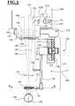
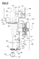
- a surgical microscope 100 is shown, to which an ophthalmoscopy attachment module 150 is connected.
- the ophthalmoscopy attachment module 150 is with a holding device 151 on a receptacle 101 for a focusable microscope main objective system 102.
- the microscope main objective system 102 includes a positive power lens 103 and a lens 104 whose refractive power is negative.
- the lens 104 may be moved relative to the lens 103 to adjust the focal plane of the surgical microscope 100.
- the microscope main objective system 102 has an optical axis 105 and is penetrated by a stereoscopic viewing beam path 106, 107, which is guided in the surgical microscope 100 through a magnification system, not shown, in order to observe an object area in an eyepiece view, likewise not shown in FIG to enable.
- the ophthalmoscopy attachment module 150 has a joint 152.
- a holding device 153 with an ophthalmoscope magnifier 154 is accommodated in the joint 152.
- the holding device 153 with the ophthalmoscope magnifier 154 can be pivoted in the joint 152 in accordance with the double arrow 160 into and out of the observation beam path 106, 107 of the surgical microscope 100.
- the holding device 153 has a first section 155 and a second section 156.
- the first section 155 comprises a guide rod 157 and a spindle drive 158.
- the second section 156 is held on the first section 155. It can be moved by moving a nut 159 according to the double arrow 161.
- the ophthalmoscope magnifier 154 is received. By moving the nut 159, the distance of the ophthalmoscope magnifier 154 from a patient's eye 190 to be examined can be adjusted.
- the ophthalmoscope magnifier 154 generates an intermediate image 191 of the background 192 of the patient's eye 190. If the microscope main objective 102 is focused on the intermediate image 191, the background 191 of the patient's eye 190 in the surgical microscope 100 can be viewed sharply.
- the surgical microscope 100 has an illumination system 120 with a light source 121.
- the light source provides illuminating light 125 via a field diaphragm 122 and lens elements 123 and 124 which reaches a deflection element 126.
- the deflecting element 126 directs the illumination light 125 through the microscope main objective system 102 to the patient's eye 190, the object area.
- a lens 180 having a positive refractive power is provided in the second section 156 of the holding device 153.
- This lens 180 acts as an illumination light coupling unit. It captures the illuminating light 125 passing through the microscope main objective system 102 and directs it to a deflecting prism 181.
- the deflecting prism 181 laterally guides the illuminating light 125 past the ophthalmoscope magnifier 154 and directs it to the patient's eye 190.
- Moving the illuminating beam path past the illuminating beam path Ophthalmoscopy magnifier 154 ensures that no disturbing reflections of illumination light on the ophthalmoscope magnifier 154 can arise, which are then captured again in the observation beam path 106, 107 of the surgical microscope.
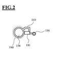
- FIG. 2 shows a section of the ophthalmoscopy attachment module 150 along the line II-II in FIG. 1.
- the second section 156 of the ophthalmoscopy attachment module carries the deflection prism 181 and the ophthalmoscopy magnifier 154 on a holding web 110 at its end pointing to the object region.
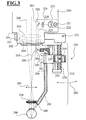
- FIG. 3 shows a surgical microscope 200 with ophthalmoscopy attachment module 250.
- the ophthalmoscopy attachment module 250 has a holding device 251, which in turn is arranged on an annular receptacle 201 for microscope main objective system 202 of the surgical microscope.
- the microscope main objective system 202 is held focusable and has a lens 203 with positive refractive power and a lens 204 whose refractive power is negative.
- the ophthalmoscopy attachment module 250 has a retainer 253 that receives a hinge 252.
- the holding device 253 carries an ophthalmoscopic magnifier 254. In the joint 252, the ophthalmoscope magnifier 254 can be pivoted on the holding device 253 in accordance with the double arrow 255 into and out of the observation beam path 205 of the surgical microscope 200.
- the holding device 253 in turn has a first portion 255 and a second portion 256.
- the first portion 255 has a guide rod 257 and a Spindle drive 258 on.
- the second section 256 is held on the first section 255. It is designed as a light guide 284 and can be moved by moving the nut 259 according to the double arrow 260.
- an illumination system 220 is provided whose structure corresponds to that of the illumination system 120 in the surgical microscope 100 of FIG. 1.
- the assemblies of the illumination system, which are already shown in Fig. 1, carry in Fig. 2 reference numerals, which are increased compared to Fig. 1 by the number 100.
- the surgical microscope 200 has an illumination light coupling unit 280, which contains a deflection mirror 281 and a deflection mirror 282. If the holding device 251, as shown in FIG. 2, is pivoted with the ophthalmoscope magnifier 254 into the observation beam path 206, 207 of the surgical microscope 200, the illumination light 225 is captured by the microscope main objective system by the deflection mirror 281 and by a lens element 283 via deflection mirror 282 an optical fiber 284 coupled.
- the light guide 284 acts as a holding device and carries the ophthalmoscope magnifier 254.
- the light guide 284 is made kinked in a portion 285 facing the object area. It passes the illumination light 225 guided through it through a lens element 286 so as to arrive in bundled fashion on the object to be examined in the form of the patient's eye 290.
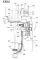
- FIG. 4 shows a surgical microscope 300 with ophthalmoscopy attachment module 350, the structure of which basically corresponds to the surgical microscope 200 with ophthalmoscopy attachment module 250 from FIG. 3.
- a light guide 384 is provided which has a gooseneck-shaped section 385.
- This gooseneck-shaped section 385 includes a fiber optic 386.
- the section 385 is like a Garden hose movable. Its course can be adjusted. In this case, the section 385 retains each shape once set by an operator.
- FIG. 5 shows a surgical microscope 400 with an ophthalmoscopy attachment module 450.
- the construction of the surgical microscope 400 with an ophthalmoscopy attachment module 450 corresponds to that of the surgical microscope 100 and the ophthalmoscopy attachment module 150 from FIG. 1.
- Corresponding assemblies and objects are therefore shown in FIG 1 in FIG. 5 with references numbered 300 increased.
- a mirror element 495 is associated with a piezo drive 496.
- the piezo drive allows the mirror element 495 to be adjusted according to the double arrows 497 and 498.
- a drive 481 is assigned to the lens element 480. This drive makes it possible to move the lens element 480 along the section 487 of the holding device 453 in accordance with the double arrow 482.
- FIG. 6 shows a surgical microscope 500 with an ophthalmoscopy attachment module 550, which has a mirror system for directing illumination light 525, which is provided in the surgical microscope 500 by means of an illumination system 520, into a patient eye 590 to be examined.
- illumination system 520 which is provided in the surgical microscope 500 by means of an illumination system 520, into a patient eye 590 to be examined.
- a first curved mirror 570 and a second curved mirror 571 are provided, which act as the illumination light coupling unit 580 and captures the illumination light 525 passing through the microscope main lens system 502 of the operation microscope 500.
- the illumination light coupling unit 580 is designed to be adjustable in accordance with the double arrows 572, 573, 574, 575 and is held on a second section 556 of the holding device 553.
- the illumination light coupling unit 580 deflects illumination light 525 to the deflection mirror 593, which are adjusted in accordance with the double arrows 594, 599 can. This deflection mirror 593 guides the illumination light past the ophthalmoscope magnifier 554 to the patient's eye 590.
- FIG. 7 shows a surgical microscope 600 with an ophthalmoscopy attachment module 650, in which, like the ophthalmoscopy attachment module 150 from FIG. 1, the ophthalmoscopy attachment module 650 is arranged by means of a holding device 651 on a receptacle 601 for a focusable microscope main objective system 602.
- the microscope main lens system 602 has a positive power lens 603 and a lens 604 whose refractive power is negative.
- a hinge 652 is provided in the ophthalmoscopy attachment module 650.
- a holding device 653 is supported, which carries an ophthalmoscopic loupe 654.
- the ophthalmoscope magnifier 654 like the ophthalmoscope magnifier 154 in the ophthalmoscopy attachment module 150 of FIG. 1, can be pivoted in and out of the observation beam path 606, 607 of the surgical microscope 600 in accordance with the double arrow 660.
- the holding device 653 has a first section 655 with a guide rod 657 and with a threaded spindle 658, on which a nut 659 acts.
- the first section 655 carries a second section 656, on which the ophthalmoscope magnifier 654 is accommodated.
- the nut 659 is associated with an adjusting motor 670. By means of the adjusting motor 670, the nut 659 can be controllably driven, whereby the second portion 656 of the holding device 653 can be moved relative to the first portion 655 corresponding to the double arrow 661.
- a light source 690 is integrated with illumination optics. This light source comprises lens elements 691 and 692.
- the light source 690 is supplied via not shown leads from the surgical microscope 600 with electrical energy. Alternatively, it is also possible to provide a battery supply for the light source.
- the illumination light 625 provided by the light source 690 after being passed through the illumination optics, is directed onto mirror surfaces 694 and 695. These mirror surfaces 694, 695 direct the illumination light 625 past the ophthalmoscope magnifier 654 to the object area in the form of the patient's eye 690.
Landscapes
- Life Sciences & Earth Sciences (AREA)
- Health & Medical Sciences (AREA)
- Medical Informatics (AREA)
- Biophysics (AREA)
- Ophthalmology & Optometry (AREA)
- Engineering & Computer Science (AREA)
- Biomedical Technology (AREA)
- Heart & Thoracic Surgery (AREA)
- Physics & Mathematics (AREA)
- Molecular Biology (AREA)
- Surgery (AREA)
- Animal Behavior & Ethology (AREA)
- General Health & Medical Sciences (AREA)
- Public Health (AREA)
- Veterinary Medicine (AREA)
- Microscoopes, Condenser (AREA)
- Eye Examination Apparatus (AREA)
Abstract
Description
- Die Erfindung betrifft ein Ophthalmoskopie-Vorsatzmodul zur Befestigung an einem Operationsmikroskop mit einer Halteeinrichtung für ein Ophthalmoskopierlupe, wobei die Halteeinrichtung eine Einrichtung zum Führen von Beleuchtungslicht trägt.
- Ein Operationsmikroskop mit einem Ophthalmoskopie-Vorsatzmodul der eingangs genannten Art ist aus der
DE 94 15 219 U1 bekannt. Dort ist als Ophthalmoskopie-Vorsatzmodul eine Vorsatzeinrichtung für ein stereoskopisches Operationsmikroskop beschrieben, das dazu dient, den Augenhintergrund eines Patientenauges zu beobachten. Die Vorsatzeinrichtung umfasst eine Ophthalmoskopierlupe in Form einer Vorsatzlinse. Sie ist in einer Halteeinrichtung mit dem Ophthalmoskopie-Vorsatzmodul unmittelbar über einem zu untersuchenden Patientenauge aufgenommen. Die Ophthalmoskopierlupe erzeugt auf ihrer dem zu untersuchenden Objekt abgewandten Seite ein Zwischenbild des Augenhintergrunds. Dieses Zwischenbild kann mit dem Operationsmikroskop, an welches das Ophthalmoskopie-Vorsatzmodul angeschlossen ist, betrachtet werden. Das Ophthalmoskopie-Vorsatzmodul weist ein Gelenk für die Halteeinrichtung der Ophthalmoskopierlupe auf. Die Ophthalmoskopierlupe kann an diesem Gelenk in und aus dem Beobachtungsstrahlengang des entsprechenden Operationsmikroskops geschwenkt werden. - Es ist möglich, das in der
DE 94 15 219 U1 beschriebene Ophthalmoskopie-Vorsatzmodul an Operationsmikroskopen einzusetzen, bei denen durch das Mikroskop-Hauptobjektiv hindurch Beleuchtungslicht für den Objektbereich bereitgestellt wird. Ein solches Operationsmikroskop ist beispielsweise das OPMI® Visu 200 der Firma Carl Zeiss. Ist bei diesem Operationsmikroskop die Ophthalmoskopierlupe vor dem Mikroskop-Hauptobjektiv in den stereoskopischen Beobachtungsstrahlengang geschwenkt, so gelangt das Beleuchtungslicht durch die Ophthalmoskopierlupe hindurch in das Patientenauge und beleuchtet den Augenhintergrund. - Wird der Beleuchtungsstrahlengang durch die Ophthalmoskopierlupe geführt, so können sich im Beobachtungsbild des Operationsmikroskops störende Lichtreflexe ergeben, die von Beleuchtungslicht herrühren, das an der Ophthalmoskopierlupe reflektiert wird. Solche Lichtreflexe sind umso ausgeprägter, wenn die Ophthalmoskopierlupe verschmutzt ist, etwa durch Bluttröpfchen. Eine Verschmutzung der Ophthalmoskopierlupe im laufenden Operationsbetrieb lässt sich jedoch nicht immer ausschließen.
- Aufgabe der Erfindung ist es daher, ein Ophthalmoskopie-Vorsatzmodul zu schaffen, das sich zum Arbeiten mit einem Operationsmikroskop eignet, bei dem Beleuchtungslicht durch das Mikroskop-Hauptobjektiv hindurch bereitgestellt wird, und bei dem dennoch keine störenden Reflexe auftreten, die von Streuungen von Beleuchtungslicht an einer Ophthalmoskopierlupe herrühren.
- Diese Aufgabe wird durch ein Ophthalmoskopie-Vorsatzmodul der eingangs genannten Art gelöst, bei dem die Einrichtung zum Führen von Beleuchtungslicht an der Ophthalmoskopierlupe vorbei Beleuchtungslicht zum Objektbereich führt.
- Auf diese Weise ist es möglich, den Beleuchtungsstrahlengang gut auf ein zu untersuchendes Objekt wie ein Patientenauge abzustimmen. Insbesondere wird so gewährleistet, dass sich die Stellung der Ophthalmoskopierlupe nicht auf den Einfallswinkel von Beleuchtungslicht auswirkt, das in den zu untersuchenden Objektbereich geführt wird.
- In Weiterbildung der Erfindung umfasst die Einrichtung zum Führen von Beleuchtungslicht wenigstens teilweise verstellbare optische Elemente. Auf diese Weise kann der Einfallswinkel für Beleuchtungslicht auf ein mittels des Ophthalmoskopie-Vorsatzmodul untersuchtes Patientenauge eingestellt werden. So ist es möglich, für den Beleuchtungsstrahlengang, der in den Objektbereich gelangt, einen Verlauf einzustellen, der für die Untersuchung eines Objektbereichs günstig ist.
- In Weiterbildung der Erfindung sind den wenigstens teilweise verstellbaren optischen Elementen Antriebe zugeordnet. Auf diese Weise ist es möglich, eine automatisierte Einstellung günstiger Beleuchtungskonfigurationen bei dem Ophthalmoskopie-Vorsatzmodul vorzusehen, so dass dieses leicht und ergonomisch günstig bedient werden kann. Darüber hinaus ermöglichen es Antriebe für die wenigstens teilweise verstellbaren optischen Elemente einen Regelkreis vorzusehen, der das Bild eines Beobachtungsbereiches auswertet und bei dem Ophthalmoskopie-Vorsatzmodul den Verlauf eines Beleuchtungsstrahlenganges gegebenenfalls bei laufendem Operationsbetrieb für ein besonders kontrastreiches oder lichtstarkes Beobachtungsbild optimiert.
- In Weiterbildung der Erfindung umfasst die Einrichtung zum Führen von Beleuchtungslicht ein oder mehrere Spiegel, ein oder mehrere Lichtleiter, ein oder mehrere Linsenelemente oder ein Ablenkprisma. Auf diese Weise ist es möglich, Beleuchtungslicht ohne Streuverluste zu einem Objektbereich zu führen, der untersucht werden soll.
- In Weiterbildung der Erfindung ist in das Ophthalmoskopie-Vorsatzmodul eine Lichtquelle integriert. Auf diese Weise kann das Ophthalmoskopie-Vorsatzmodul bei Operationsmikroskopen eingesetzt werden, in denen keine Beleuchtungseinheit vorgesehen ist, die Beleuchtungslicht abgibt.
- In Weiterbildung der Erfindung ist bei dem Ophthalmoskopie-Vorsatzmodul eine Beleuchtungslicht-Einkoppeleinheit vorgesehen, um von dem Operationsmikroskop bereitgestelltes Beleuchtungslicht aufzunehmen. Vorzugsweise ist die Beleuchtungslicht-Einkoppeleinheit zur Aufnahme von Beleuchtungslicht ausgelegt, welches das Mikroskop-Hauptobjektiv des Operationsmikroskops durchsetzt.
- Ein Operationsmikroskop mit einem entsprechenden Ophthalmoskopie-Vorsatzmodul ermöglicht eine von störenden Reflexen befreite Beobachtung des Augenhintergrunds eines Patientenauges.
- Vorteilhafte Ausführungsformen der Erfindung sind in den Zeichnungen dargestellt und werden nachfolgend beschrieben.
- Es zeigen:
- Fig. 1
- ein Operationsmikroskop mit einem Ophthalmoskopie-Vorsatzmodul, in das zum Führen des Beleuchtungsstrahlenganges ein Ablenkprisma integriert ist;
- Fig. 2
- einen Schnitt des Ophthalmoskopie-Vorsatzmoduls aus Fig. 1 entlang der Linie II - II;
- Fig. 3
- ein Operationsmikroskop mit Ophthalmoskopie-Vorsatzmodul, in das zum Führen des Beleuchtungsstrahlenganges ein Lichtleiter vorgesehen ist;
- Fig. 4
- ein Operationsmikroskop mit einer alternativen Ausführungsform für ein Ophthalmoskopie-Vorsatzmodul mit einem Lichtleiter im Beleuchtungsstrahlengang, um Beleuchtungslicht zum Objektbereich zu führen;
- Fig. 5
- ein Operationsmikroskop mit Ophthalmoskopie-Vorsatzmodül, welches zum Führen von Beleuchtungslicht ein Spiegelsystem hat;
- Fig. 6
- ein Operationsmikroskop mit einer alternativen Ausführungsform für ein Ophthalmoskopie-Vorsatzmodul, bei dem zum Führen von Beleuchtungslicht ein Spiegelsystem vorgesehen ist; und
- Fig. 7
- ein Operationsmikroskop mit Ophthalmoskopie-Vorsatzmodul, das eine integrierte Lichtquelle aufweist.
- In Fig. 1 ist ein Operationsmikroskop 100 gezeigt, an welches ein Ophthalmoskopie-Vorsatzmodul 150 angeschlossen ist. Das Ophthalmoskopie-Vorsatzmodul 150 ist mit einer Halteeinrichtung 151 an einer Aufnahme 101 für ein fokussierbares Mikroskop-Hauptobjektivsystem 102 angeordnet. Das Mikroskop-Hauptobjektivsystem 102 umfasst eine Linse 103 mit positiver Brechkraft und eine Linse 104, deren Brechkraft negativ ist. Die Linse 104 kann relativ zu der Linse 103 bewegt werden, um die Fokusebene des Operationsmikroskops 100 einzustellen. Das Mikroskop-Hauptobjektivsystem 102 hat eine optische Achse 105 und wird von einem stereoskopischen Beobachtungsstrahlengang 106, 107 durchsetzt, der in dem Operationsmikroskop 100 durch ein nicht weiter dargestelltes Vergrößerungssystem geführt ist, um in einem in Fig. 2 ebenfalls nicht gezeigten Okulareinblick das Betrachten eines Objektbereichs zu ermöglichen.
- Das Ophthalmoskopie-Vorsatzmodul 150 hat ein Gelenk 152. In dem Gelenk 152 ist eine Halteeinrichtung 153 mit Ophthalmoskopierlupe 154 aufgenommen. Die Halteeinrichtung 153 mit der Ophthalmoskopierlupe 154 kann in dem Gelenk 152 entsprechend dem Doppelpfeil 160 in und aus dem Beobachtungsstrahlengang 106, 107 des Operationsmikroskops 100 geschwenkt werden.
- Die Halteeinrichtung 153 hat einen ersten Abschnitt 155 und einen zweiten Abschnitt 156. Der erste Abschnitt 155 umfasst eine Führungsstange 157 und einen Spindeltrieb 158. Der zweite Abschnitt 156 ist an dem ersten Abschnitt 155 gehalten. Er kann durch Bewegen einer Mutter 159 entsprechend dem Doppelpfeil 161 bewegt werden. An dem zweiten Abschnitt 156 ist die Ophthalmoskopierlupe 154 aufgenommen. Durch Bewegen der Mutter 159 lässt sich der Abstand der Ophthalmoskopierlupe 154 von einem Patientenauge 190, das untersucht werden soll, einstellen.
- Die Ophthalmoskopierlupe 154 erzeugt ein Zwischenbild 191 des Hintergrunds 192 des Patientenauges 190. Ist das Mikroskop-Hauptobjektiv 102 auf das Zwischenbild 191 fokussiert, kann der Hintergrund 191 des Patientenauges 190 im Operationsmikroskop 100 scharf betrachtet werden.
- Das Operationsmikroskop 100 hat ein Beleuchtungssystem 120 mit einer Lichtquelle 121. Die Lichtquelle stellt über eine Leuchtfeldblende 122 und Linsenelemente 123 und 124 Beleuchtungslicht 125 bereit, das auf ein Umlenkelement 126 gelangt. Das Umlenkelement 126 lenkt das Beleuchtungslicht 125 durch das Mikroskops-Hauptobjektivsystem 102 zum Patientenauge 190, dem Objektbereich.
- Für das aus dem Mikroskop-Hauptobjektivsystem 102 austretende Beleuchtungslicht 125 ist im zweiten Abschnitt 156 der Halteeinrichtung 153 eine Linse 180 mit positiver Brechkraft vorgesehen. Diese Linse 180 wirkt als Beleuchtungslicht-Einkoppeleinheit. Sie fängt das Beleuchtungslicht 125, das durch das Mikroskop-Hauptobjektivsystem 102 gelangt, ein und leitet es zu einem Ablenkprisma 181. Das Ablenkprisma 181 führt das Beleuchtungslicht 125 an der Ophthalmoskopierlupe 154 seitlich vorbei und lenkt es zum Patientenauge 190. Das Vorbeiführen des Beleuchtungsstrahlenganges an der Ophthalmöskopierlupe 154 gewährleistet, dass keine störenden Reflexe von Beleuchtungslicht an der Ophthalmoskopierlupe 154 entstehen können, die dann wieder in dem Beobachtungsstrahlengang 106, 107 des Operationsmikroskops eingefangen werden.
- Die Fig. 2 zeigt einen Schnitt des Ophthalmoskopie-Vorsatzmoduls 150 entlang der Linie II - II in Fig. 1. Der zweite Abschnitt 156 des Ophthalmoskopie-Vorsatzmoduls trägt an seinen zum Objektbereich weisenden Ende das Umlenkprisma 181 und die Ophthalmoskopierlupe 154 an einem Haltesteg 110.
- In Fig. 3 ist ein Operationsmikroskop 200 mit Ophthalmoskopie-Vorsatzmodul 250 gezeigt. Das Ophthalmoskopie-Vorsatzmodul 250 hat eine Halteeinrichtung 251, welche wiederum an einer ringförmigen Aufnahme 201 für Mikroskop-Hauptobjektivsystem 202 des Operationsmikroskops angeordnet ist. Das Mikroskop-Hauptobjektivsystem 202 ist fokussierbar gehalten und hat eine Linse 203 mit positiver Brechkraft und eine Linse 204, deren Brechkraft negativ ist. Das Ophthalmoskopie-Vorsatzmodul 250 hat eine Halteeinrichtung 253, die ein Gelenk 252 aufgenommen ist. Die Halteeinrichtung 253 trägt eine Ophthalmoskopierlupe 254. In dem Gelenk 252 kann die Ophthalmoskopierlupe 254 an der Halteeinrichtung 253 entsprechend dem Doppelpfeil 255 in und aus dem Beobachtungsstrahlengang 205 des Operationsmikroskops 200 geschwenkt werden.
- Die Halteeinrichtung 253 hat wiederum einen ersten Abschnitt 255 und einen zweiten Abschnitt 256. Der erste Abschnitt 255 weist eine Führungsstange 257 und einen Spindeltrieb 258 auf. Der zweite Abschnitt 256 ist an dem ersten Abschnitt 255 gehalten. Er ist als Lichtleiter 284 ausgebildet und kann durch Bewegen der Mutter 259 entsprechend dem Doppelpfeil 260 bewegt werden.
- In dem Operationsmikroskop 200 ist ein Beleuchtungssystem 220 vorgesehen, dessen Aufbau demjenigen des Beleuchtungssystems 120 im Operationsmikroskop 100 aus Fig. 1 entspricht. Die Baugruppen des Beleuchtungssystems, die schon in Fig. 1 gezeigt sind, tragen in Fig. 2 Bezugszeichen, die im Vergleich zu Fig. 1 um die Zahl 100 erhöht sind.
- Das Operationsmikroskop 200 hat eine Beleuchtungslicht-Einkoppeleinheit 280, die einen Umlenkspiegel 281 und einen Umlenkspiegel 282 enthält. Ist die Halteeinrichtung 251, wie in Fig. 2 gezeigt, mit der Ophthalmoskopierlupe 254 in den Beobachtungsstrahlengang 206, 207 des Operationsmikroskops 200 geschwenkt, so wird das Beleuchtungslicht 225 aus dem Mikroskop-Hauptobjektivsystem vom Umlenkspiegel 281 eingefangen und über Umlenkspiegel 282 durch ein Linsenelement 283 in einen Lichtleiter 284 eingekoppelt. Der Lichtleiter 284 wirkt als Halteeinrichtung und trägt die Ophthalmoskopierlupe 254. Er ist in einem Abschnitt 255 der Halteeinrichtung 253 aufgenommen und kann durch Bewegen einer Mutter 258 derart verlagert werden, dass sich die Ophthalmoskopierlupe 254 entsprechend dem Doppelpfeil 260 heben und senken lässt. Der Lichtleiter 284 ist in einem zum Objektbereich weisenden Abschnitt 285 geknickt ausgeführt. Er leitet das durch ihn geleitete Beleuchtungslicht 225 durch ein Linsenelement 286, um so gebündelt auf das zu untersuchende Objekt in Form des Patientenauges 290 zu gelangen.
- Die Fig. 4 zeigt ein Operationsmikroskop 300 mit Ophthalmoskopie-Vorsatzmodul 350, dessen Aufbau grundsätzlich dem Operationsmikroskop 200 mit Ophthalmoskopie-Vorsatzmodul 250 aus Fig. 3 entspricht. Baugruppen, die bei den in Fig. 3 und Fig. 4 gezeigten Operationsmikroskop mit Ophthalmoskopie-Vorsatzmodul identisch sind, tragen in Fig. 4 Bezugszeichen, die im Vergleich zu Fig. 3 um die Zahl 100 erhöht sind. Bei dem Ophthalmoskopie-Vorsatzmodul 350 ist ein Lichtleiter 384 vorgesehen, der einen schwanenhalsförmig ausgebildeten Abschnitt 385 aufweist. Dieser schwanenhalsförmig ausgebildete Abschnitt 385 enthält eine Faseroptik 386. Der Abschnitt 385 ist wie ein Gartenschlauch bewegbar. Sein Verlauf kann eingestellt werden. Der Abschnitt 385 behält dabei eine jede von einer Bedienperson einmal eingestellte Form bei.
- Die Fig. 5 zeigt ein Operationsmikroskop 400 mit Ophthalmoskopie-Vorsatzmodul 450. Der Aufbau des Operationsmikroskops 400 mit Ophthalmoskopie-Vorsatzmodul 450 entspricht demjenigen von Operationsmikroskop 100 und Ophthalmoskopie-Vorsatzmodul 150 aus Fig. 1. Einander entsprechende Baugruppen und Gegenstände sind daher im Vergleich zur Fig. 1 in Fig. 5 mit um die Zahl 300 erhöhten Bezugszeichen versehen.
- Anders als das Ophthalmoskopie-Vorsatzmodul 150 aus Fig. 1 gibt es bei dem Ophthalmoskopie-Vorsatzmodul 450 kein Ablenkprisma sondern ein Spiegelelement 495 vorgesehen. Diesem Spiegelelement 495 ist ein Piezo-Antrieb 496 zugeordnet. Der Piezo-Antrieb ermöglicht, das Spiegelelement 495 entsprechend der Doppelpfeile 497 und 498 zu verstellen. Gleichzeitig ist dem Linsenelement 480 ein Antrieb 481 zugeordnet. Dieser Antrieb ermöglicht, das Linsenelement 480 entsprechend dem Doppelpfeil 482 am Abschnitt 487 der Halteeinrichtung 453 entlang zu bewegen.
- Die Fig. 6 zeigt ein Operationsmikroskop 500 mit einem Ophthalmoskopie-Vorsatzmodul 550, das ein Spiegelsystem aufweist, um Beleuchtungslicht 525, das mittels eines Beleuchtungssystems 520 im Operationsmikroskop 500 bereitgestellt wird, in ein zu untersuchendes Patientenauge 590 zu lenken. Soweit Baugruppen und Gegenstände in Fig. 5 und Fig. 6 identisch sind, tragen sie in Fig. 6 im Vergleich zu Fig. 5 um die Zahl 100 erhöhte Bezugszahlen.
- Bei dem Ophthalmoskopie-Vorsatzmodul 550 ist ein erster gekrümmter Spiegel 570 und ein zweiter gekrümmter Spiegel 571 vorgesehen, die als Beleuchtungslicht-Einkoppeleinheit 580 wirken und das Beleuchtungslicht 525 einfängt, welches durch das Mikroskop-Hauptobjektivsystem 502 des Operationsmikroskops 500 tritt. Die Beleuchtungslicht-Einkoppeleinheit 580 ist entsprechend der Doppelpfeile 572, 573, 574, 575 verstellbar ausgeführt und wird an einem zweiten Abschnitt 556 der Halteeinrichtung 553 gehalten. Die Beleuchtungslicht-Einkoppeleinheit 580 lenkt Beleuchtungslicht 525 zum Umlenkspiegel 593, der entsprechend der Doppelpfeile 594, 599 verstellt werden kann. Dieser Umlenkspiegel 593 führt das Beleuchtungslicht an der Ophthalmoskopierlupe 554 vorbei zum Patientenauge 590.
- In Fig. 7 ist ein Operationsmikroskop 600 mit Ophthalmoskopie-Vorsatzmodul 650 gezeigt, bei dem wie beim Ophthalmoskopie-Vorsatzmodul 150 aus Fig. 1 das Ophthalmoskopie-Vorsatzmodul 650 mittels einer Halteeinrichtung 651 an einer Aufnahme 601 für ein fokussierbares Mikroskop-Hauptobjektivsystem 602 angeordnet ist. Das Mikroskop-Hauptobjektivssystem 602 hat eine Linse 603 mit positiver Brechkraft und eine Linse 604, deren Brechkraft negativ ist. Bei dem Ophthalmoskopie-Vorsatzmodul 650 ist ein Gelenk 652 vorgesehen. In dem Gelenk 652 ist eine Halteeinrichtung 653 gehalten, die eine Ophthalmoskopierlupe 654 trägt. Die Ophthalmoskopierlupe 654 kann wie die Ophthalmoskopierlupe 154 beim Ophthalmoskopie-Vorsatzmodul 150 aus Fig. 1 entsprechend dem Doppelpfeil 660 in und aus dem Beobachtungsstrahlengang 606, 607 des Operationsmikroskops 600 geschwenkt werden.
- Die Halteeinrichtung 653 hat einen ersten Abschnitt 655 mit einer Führungsstange 657 und mit einer Gewindespindel 658, auf die eine Mutter 659 wirkt. Der erste Abschnitt 655 trägt einen zweiten Abschnitt 656, an welchem die Ophthalmoskopierlupe 654 aufgenommen ist. Der Mutter 659 ist ein Verstellmotor 670 zugeordnet. Mittels des Verstellmotors 670 kann die Mutter 659 steuerbar angetrieben werden, wodurch der zweite Abschnitt 656 der Halteeinrichtung 653 relativ zu dem ersten Abschnitt 655 entsprechend des Doppelpfeils 661 bewegt werden kann. In dem zweiten Abschnitt 656 ist eine Lichtquelle 690 mit Beleuchtungsoptik integriert. Diese Lichtquelle umfasst Linsenelemente 691 und 692. Die Lichtquelle 690 ist über nicht weiter dargestellte Zuleitungen aus dem Operationsmikroskop 600 mit elektrischer Energie versorgt. Alternativ ist es auch möglich, für die Lichtquelle eine Batteriespeisung vorzusehen.
- Das von der Lichtquelle 690 bereitgestellte Beleuchtungslicht 625 wird, nachdem es durch die Beleuchtungsoptik geführt ist, auf Spiegelflächen 694 und 695 geleitet. Diese Spiegelflächen 694, 695 lenken das Beleuchtungslicht 625 an der Ophthalmoskopierlupe 654 vorbei zum Objektbereich in Form des Patientenauges 690.
Claims (11)
- Ophthalmoskopie-Vorsatzmodul (150, 250, 350, 450, 550, 650) zur Befestigung an einem Operationsmikroskop (100, 200, 300, 400, 500, 600)- mit einer Halteeinrichtung (153, 253, 353, 453, 553, 653) für eine Ophthalmoskopierlupe (154, 254, 354, 454, 554, 654); wobei- die Halteeinrichtung (153, 253, 353, 453, 553, 653) eine Einrichtung (180, 181, 281, 282, 283, 284, 285, 286, 381, 382, 383, 384, 385, 480, 495, 570, 571, 593, 691, 692, 694, 695) zum Führen von Beleuchtungslicht trägt;dadurch gekennzeichnet, dass- die Einrichtung zum Führen von Beleuchtungslicht (180, 181, 281, 282, 283, 284, 285, 286, 381, 382, 383, 384, 385, 480, 495, 570, 571, 593, 691, 692, 694, 695) Beleuchtungslicht (125, 225, 325, 425, 525, 625) an der Ophthalmoskopierlupe (154, 254, 354, 454, 554, 654) vorbei zum Objektbereich (190, 290, 390, 490, 590, 690) führt.
- Ophthalmoskopie-Vorsatzmodul nach Anspruch 1, dadurch gekennzeichnet, dass die Einrichtung (385, 480, 495, 570, 571, 593) zum Führen von Beleuchtungslicht (325, 425, 525) wenigstens teilweise verstellbare optische Elemente (386, 480, 495, 570, 571, 593) umfasst.
- Ophthalmoskopie-Vorsatzmodul nach Anspruch 2, dadurch gekennzeichnet, dass den wenigstens teilweise verstellbaren optischen Elementen Antriebe (481, 496) zugeordnet sind.
- Ophthalmoskopie-Vorsatzmodul nach einem der Ansprüche 1 bis 3, dadurch gekennzeichnet, dass die Einrichtung zum Führen von Beleuchtungslicht eine oder mehrere Spiegel (281, 282, 381, 384, 495, 570, 571, 593) umfasst.
- Ophthalmoskopie-Vorsatzmodul nach einem der Ansprüche 1 bis 4, dadurch gekennzeichnet, dass die Einrichtung zum Führen von Beleuchtungslicht eine oder mehrere Lichtleiter (284, 384, 385) umfasst.
- Ophthalmoskopie-Vorsatzmodul nach einem der Ansprüche 1 bis 5, dadurch gekennzeichnet, dass die Einrichtung zum Führen von Beleuchtungslicht ein oder mehrere Linsenelemente (180, 283, 286, 383, 480) umfasst.
- Ophthalmoskopie-Vorsatzmodul nach einem der Ansprüche 1 bis 6, dadurch gekennzeichnet, dass die Einrichtung zum Führen von Beleuchtungslicht ein Ablenkprisma (181) umfasst.
- Ophthalmoskopie-Vorsatzmodul nach einem der Ansprüche 1 bis 7, dadurch gekennzeichnet, dass in das Ophthalmoskopie-Vorsatzmodul (650) eine Lichtquelle (690) integriert ist.
- Ophthalmoskopie-Vorsatzmodul nach einem der Ansprüche 1 bis 8, dadurch gekennzeichnet, dass eine Beleuchtungslicht-Einkoppeleinheit (180, 280, 380, 480, 580) vorgesehen ist, um von dem Operationsmikroskop (100, 200, 300, 400, 500) bereitgestelltes Beleuchtungslicht (125, 225, 325, 425, 525) aufzunehmen.
- Ophthalmoskopie-Vorsatzmodul nach Anspruch 9, dadurch gekennzeichnet, dass die Beleuchtungslicht-Einkoppeleinheit (180, 280, 380, 480, 580) zur Aufnahme von Beleuchtungslicht (125, 225, 325, 425, 525) ausgelegt ist, welches das Mikroskop-Hauptobjektiv (102, 202, 302, 402, 502) durchsetzt.
- Operationsmikroskop (100, 200, 300, 400, 500, 600) mit einem Ophthalmoskopie-Vorsatzmodul (150, 250, 350, 450, 550, 660) gemäß einem der Ansprüche 1 bis 10.
Applications Claiming Priority (1)
| Application Number | Priority Date | Filing Date | Title |
|---|---|---|---|
| DE102006038911A DE102006038911A1 (de) | 2006-08-18 | 2006-08-18 | Ophthalmoskopie-Vorsatzmodul und Operationsmikroskop mit Ophthalmoskopie-Vorsatzzmodul |
Publications (2)
| Publication Number | Publication Date |
|---|---|
| EP1889567A2 true EP1889567A2 (de) | 2008-02-20 |
| EP1889567A3 EP1889567A3 (de) | 2008-03-12 |
Family
ID=38859046
Family Applications (1)
| Application Number | Title | Priority Date | Filing Date |
|---|---|---|---|
| EP07013850A Withdrawn EP1889567A3 (de) | 2006-08-18 | 2007-07-14 | Ophthalmoskopie-Vorsatzmodul für ein Operationsmikroskop |
Country Status (4)
| Country | Link |
|---|---|
| US (1) | US20080204660A1 (de) |
| EP (1) | EP1889567A3 (de) |
| JP (1) | JP2008043771A (de) |
| DE (1) | DE102006038911A1 (de) |
Cited By (4)
| Publication number | Priority date | Publication date | Assignee | Title |
|---|---|---|---|---|
| EP2108308A1 (de) * | 2008-04-10 | 2009-10-14 | Kowa Company Ltd. | Augenlichtstimulationsvorrichtung |
| EP2244118A1 (de) * | 2009-04-20 | 2010-10-27 | Dieter Mann GmbH | Vorsatzhalterung für Operationsmikroskop |
| DE102009058792B3 (de) * | 2009-12-18 | 2011-09-01 | Carl Zeiss Surgical Gmbh | Optische Beobachtungseinrichtung zur Beobachtung eines Auges |
| CN102917634A (zh) * | 2010-03-23 | 2013-02-06 | 神经视觉成像有限责任公司 | 对眼睛成像的装置和方法 |
Families Citing this family (7)
| Publication number | Priority date | Publication date | Assignee | Title |
|---|---|---|---|---|
| JP5030669B2 (ja) * | 2007-05-31 | 2012-09-19 | 興和株式会社 | レンズ支持装置、眼底画像取得装置、及び眼底画像取得システム |
| DE102011007607B3 (de) | 2011-04-18 | 2012-08-02 | Leica Microsystems (Schweiz) Ag | Operationsmikroskopsystem |
| EP2790606B1 (de) * | 2011-12-14 | 2015-12-09 | Universität Bern | Automatisches bildoptimierungssystem, insbesondere für stereomikroskope |
| DE102013105770B4 (de) * | 2013-06-05 | 2022-01-27 | Carl Zeiss Meditec Ag | Fundus-Abbildungssystem für ein Operationsmikroskop sowie Operationsmikroskop |
| JP2018018039A (ja) * | 2016-07-29 | 2018-02-01 | 株式会社ニデック | 手術顕微鏡 |
| US20240411119A1 (en) * | 2021-10-22 | 2024-12-12 | University Of Tsukuba | Intraocular illumination device and intraocular illumination attachment |
| CA3259620A1 (en) * | 2022-08-03 | 2024-02-08 | Alcon Inc. | OPHTHALMIC VISUALIZATION DEVICES |
Citations (3)
| Publication number | Priority date | Publication date | Assignee | Title |
|---|---|---|---|---|
| DE323162C (de) | 1914-07-15 | 1920-07-16 | Schmidt & Haensch Franz | Reflexloser Augenspiegel nach Thorner mit Stereoskopansatz fuer binokulare Beobachtung des Augenhintergrundes |
| DE2930238A1 (de) | 1979-07-26 | 1981-02-12 | Moeller J D Optik | Stereoskopisches operationsmikroskop, insbesondere fuer augenoperationen |
| DE9415219U1 (de) | 1994-09-22 | 1994-11-24 | Oculus Optikgeräte GmbH, 35582 Wetzlar | Vorsatzeinrichtung für ein Mikroskop |
Family Cites Families (6)
| Publication number | Priority date | Publication date | Assignee | Title |
|---|---|---|---|---|
| DE4232280A1 (de) * | 1992-09-25 | 1994-03-31 | Optec Ges Fuer Optische Techni | Retinoskop mit Lichtleiterbeleuchtung |
| DE9217517U1 (de) * | 1992-12-22 | 1993-02-25 | Fa. Carl Zeiss, 7920 Heidenheim | Vorsatz für ein Operationsmikroskop |
| DE29819341U1 (de) * | 1998-10-29 | 1999-03-04 | Oculus Optikgeräte GmbH, 35582 Wetzlar | Optisches System zur Beobachtung und zum Fotografieren des Augeninneren |
| FR2830185B1 (fr) * | 2001-10-02 | 2004-07-09 | Didier Ducournau | Microscope a lampe a fente pour la microchirurgie oculaire |
| DE10302401A1 (de) * | 2003-01-21 | 2004-07-29 | Leica Microsystems (Schweiz) Ag | Operationsmikroskop |
| EP2444021B8 (de) * | 2004-04-20 | 2018-04-18 | Alcon Research, Ltd. | Integriertes chirurgisches Mikroskop und Wellenfrontsensor |
-
2006
- 2006-08-18 DE DE102006038911A patent/DE102006038911A1/de not_active Ceased
-
2007
- 2007-07-14 EP EP07013850A patent/EP1889567A3/de not_active Withdrawn
- 2007-08-15 US US11/889,686 patent/US20080204660A1/en not_active Abandoned
- 2007-08-17 JP JP2007212734A patent/JP2008043771A/ja active Pending
Patent Citations (3)
| Publication number | Priority date | Publication date | Assignee | Title |
|---|---|---|---|---|
| DE323162C (de) | 1914-07-15 | 1920-07-16 | Schmidt & Haensch Franz | Reflexloser Augenspiegel nach Thorner mit Stereoskopansatz fuer binokulare Beobachtung des Augenhintergrundes |
| DE2930238A1 (de) | 1979-07-26 | 1981-02-12 | Moeller J D Optik | Stereoskopisches operationsmikroskop, insbesondere fuer augenoperationen |
| DE9415219U1 (de) | 1994-09-22 | 1994-11-24 | Oculus Optikgeräte GmbH, 35582 Wetzlar | Vorsatzeinrichtung für ein Mikroskop |
Cited By (7)
| Publication number | Priority date | Publication date | Assignee | Title |
|---|---|---|---|---|
| EP2108308A1 (de) * | 2008-04-10 | 2009-10-14 | Kowa Company Ltd. | Augenlichtstimulationsvorrichtung |
| US7815312B2 (en) | 2008-04-10 | 2010-10-19 | Kowa Company Ltd. | Ocular light stimulus apparatus |
| EP2244118A1 (de) * | 2009-04-20 | 2010-10-27 | Dieter Mann GmbH | Vorsatzhalterung für Operationsmikroskop |
| US8272737B2 (en) | 2009-04-20 | 2012-09-25 | Dieter Mann Gmbh | Wide-angle observation at a surgical microscope |
| DE102009058792B3 (de) * | 2009-12-18 | 2011-09-01 | Carl Zeiss Surgical Gmbh | Optische Beobachtungseinrichtung zur Beobachtung eines Auges |
| US10078205B2 (en) | 2009-12-18 | 2018-09-18 | Carl Zeiss Meditec Ag | Optical observation device for observing an eye |
| CN102917634A (zh) * | 2010-03-23 | 2013-02-06 | 神经视觉成像有限责任公司 | 对眼睛成像的装置和方法 |
Also Published As
| Publication number | Publication date |
|---|---|
| US20080204660A1 (en) | 2008-08-28 |
| EP1889567A3 (de) | 2008-03-12 |
| DE102006038911A1 (de) | 2008-02-21 |
| JP2008043771A (ja) | 2008-02-28 |
Similar Documents
| Publication | Publication Date | Title |
|---|---|---|
| EP1889567A2 (de) | Ophthalmoskopie-Vorsatzmodul für ein Operationsmikroskop | |
| EP1918755B1 (de) | Ophthalmo-Operationsmikroskop mit OCT-System | |
| DE10262323B4 (de) | Operationsmikroskop | |
| DE102016001659B4 (de) | Augenoperationsmikroskop und Augenoperationszusatzgerät | |
| EP1682058B1 (de) | Adapter zum koppeln einer laserbearbeitungsvorrichtung mit einem objekt | |
| EP1908398B1 (de) | Ophthalmo-Operationsmikroskopsystem | |
| EP1423746B1 (de) | Mikroskop | |
| EP1918756B1 (de) | Operationsmikroskop mit OCT-System und Operationsmikroskop-Beleuchtungsmodul mit OCT-System | |
| EP1326117B2 (de) | Ophtalmoskopie-Vorsatzmodul und Operationsmikroskop | |
| EP1227355B2 (de) | Mikroskop zur Weitwinkelbeobachtung, insbesondere für Augenoperationen | |
| DE102010039950B4 (de) | Mikroskop mit Mikro- und Makro-Objektiven | |
| DE102009036913B4 (de) | Operationsmikroskop mit Beleuchtungseinrichtung | |
| DE102007019679A1 (de) | Operationsmikroskop mit OCT-System | |
| DD202477A5 (de) | Durchlicht- und/oder auflicht-inversmikroskop | |
| DE4116385A1 (de) | Stereoskopisches mikroskop | |
| WO2006008025A1 (de) | Vorrichtung zur bearbeitung eines objektes mittels laser-strahlung | |
| DE102007029893A1 (de) | Mikroskop mit zentrierter Beleuchtung | |
| DE102007029896B3 (de) | Mikroskop mit zentrierter Beleuchtung | |
| DE60222624T2 (de) | Mikroskop mit veränderlicher Vergrösserung | |
| DE102011114523A1 (de) | Modul zur Weiterleitung eines Lichtstrahls | |
| DE10144067A1 (de) | Prismenkonstruktion für Simultane 0 DEG - und Schräg-Beleuchtung eines Stereo-Operationsmikroskops | |
| DE29819341U1 (de) | Optisches System zur Beobachtung und zum Fotografieren des Augeninneren | |
| EP1006390B1 (de) | Endomikroskopsystem | |
| CH649634A5 (de) | Vergleichsmakroskop und/oder -mikroskop. | |
| DE102007029894A1 (de) | Mikroskop mit zentrierter Beleuchtung |
Legal Events
| Date | Code | Title | Description |
|---|---|---|---|
| PUAI | Public reference made under article 153(3) epc to a published international application that has entered the european phase |
Free format text: ORIGINAL CODE: 0009012 |
|
| PUAL | Search report despatched |
Free format text: ORIGINAL CODE: 0009013 |
|
| AK | Designated contracting states |
Kind code of ref document: A2 Designated state(s): AT BE BG CH CY CZ DE DK EE ES FI FR GB GR HU IE IS IT LI LT LU LV MC MT NL PL PT RO SE SI SK TR |
|
| AX | Request for extension of the european patent |
Extension state: AL BA HR MK YU |
|
| AK | Designated contracting states |
Kind code of ref document: A3 Designated state(s): AT BE BG CH CY CZ DE DK EE ES FI FR GB GR HU IE IS IT LI LT LU LV MC MT NL PL PT RO SE SI SK TR |
|
| AX | Request for extension of the european patent |
Extension state: AL BA HR MK YU |
|
| RIC1 | Information provided on ipc code assigned before grant |
Ipc: A61B 3/13 20060101ALI20080207BHEP Ipc: A61B 3/12 20060101AFI20080109BHEP |
|
| 17P | Request for examination filed |
Effective date: 20080908 |
|
| 17Q | First examination report despatched |
Effective date: 20081020 |
|
| AKX | Designation fees paid |
Designated state(s): DE ES FR GB IT |
|
| STAA | Information on the status of an ep patent application or granted ep patent |
Free format text: STATUS: THE APPLICATION IS DEEMED TO BE WITHDRAWN |
|
| 18D | Application deemed to be withdrawn |
Effective date: 20110118 |