EP1889988A2 - Assembly structure and procedure for concrete towers used in wind turbines - Google Patents
Assembly structure and procedure for concrete towers used in wind turbines Download PDFInfo
- Publication number
- EP1889988A2 EP1889988A2 EP06027134A EP06027134A EP1889988A2 EP 1889988 A2 EP1889988 A2 EP 1889988A2 EP 06027134 A EP06027134 A EP 06027134A EP 06027134 A EP06027134 A EP 06027134A EP 1889988 A2 EP1889988 A2 EP 1889988A2
- Authority
- EP
- European Patent Office
- Prior art keywords
- section
- procedure
- erection
- assembly
- segments
- Prior art date
- Legal status (The legal status is an assumption and is not a legal conclusion. Google has not performed a legal analysis and makes no representation as to the accuracy of the status listed.)
- Granted
Links
Images




Classifications
-
- E—FIXED CONSTRUCTIONS
- E04—BUILDING
- E04H—BUILDINGS OR LIKE STRUCTURES FOR PARTICULAR PURPOSES; SWIMMING OR SPLASH BATHS OR POOLS; MASTS; FENCING; TENTS OR CANOPIES, IN GENERAL
- E04H12/00—Towers; Masts or poles; Chimney stacks; Water-towers; Methods of erecting such structures
- E04H12/02—Structures made of specified materials
- E04H12/12—Structures made of specified materials of concrete or other stone-like material, with or without internal or external reinforcements, e.g. with metal coverings, with permanent form elements
-
- F—MECHANICAL ENGINEERING; LIGHTING; HEATING; WEAPONS; BLASTING
- F03—MACHINES OR ENGINES FOR LIQUIDS; WIND, SPRING, OR WEIGHT MOTORS; PRODUCING MECHANICAL POWER OR A REACTIVE PROPULSIVE THRUST, NOT OTHERWISE PROVIDED FOR
- F03D—WIND MOTORS
- F03D13/00—Assembly, mounting or commissioning of wind motors; Arrangements specially adapted for transporting wind motor components
- F03D13/20—Arrangements for mounting or supporting wind motors; Masts or towers for wind motors
-
- E—FIXED CONSTRUCTIONS
- E04—BUILDING
- E04H—BUILDINGS OR LIKE STRUCTURES FOR PARTICULAR PURPOSES; SWIMMING OR SPLASH BATHS OR POOLS; MASTS; FENCING; TENTS OR CANOPIES, IN GENERAL
- E04H12/00—Towers; Masts or poles; Chimney stacks; Water-towers; Methods of erecting such structures
- E04H12/34—Arrangements for erecting or lowering towers, masts, poles, chimney stacks, or the like
-
- E—FIXED CONSTRUCTIONS
- E04—BUILDING
- E04H—BUILDINGS OR LIKE STRUCTURES FOR PARTICULAR PURPOSES; SWIMMING OR SPLASH BATHS OR POOLS; MASTS; FENCING; TENTS OR CANOPIES, IN GENERAL
- E04H12/00—Towers; Masts or poles; Chimney stacks; Water-towers; Methods of erecting such structures
- E04H12/34—Arrangements for erecting or lowering towers, masts, poles, chimney stacks, or the like
- E04H12/342—Arrangements for stacking tower sections on top of each other
-
- E—FIXED CONSTRUCTIONS
- E04—BUILDING
- E04H—BUILDINGS OR LIKE STRUCTURES FOR PARTICULAR PURPOSES; SWIMMING OR SPLASH BATHS OR POOLS; MASTS; FENCING; TENTS OR CANOPIES, IN GENERAL
- E04H12/00—Towers; Masts or poles; Chimney stacks; Water-towers; Methods of erecting such structures
- E04H12/34—Arrangements for erecting or lowering towers, masts, poles, chimney stacks, or the like
- E04H12/345—Arrangements for tilting up whole structures or sections thereof
-
- Y—GENERAL TAGGING OF NEW TECHNOLOGICAL DEVELOPMENTS; GENERAL TAGGING OF CROSS-SECTIONAL TECHNOLOGIES SPANNING OVER SEVERAL SECTIONS OF THE IPC; TECHNICAL SUBJECTS COVERED BY FORMER USPC CROSS-REFERENCE ART COLLECTIONS [XRACs] AND DIGESTS
- Y02—TECHNOLOGIES OR APPLICATIONS FOR MITIGATION OR ADAPTATION AGAINST CLIMATE CHANGE
- Y02E—REDUCTION OF GREENHOUSE GAS [GHG] EMISSIONS, RELATED TO ENERGY GENERATION, TRANSMISSION OR DISTRIBUTION
- Y02E10/00—Energy generation through renewable energy sources
- Y02E10/70—Wind energy
- Y02E10/72—Wind turbines with rotation axis in wind direction
-
- Y—GENERAL TAGGING OF NEW TECHNOLOGICAL DEVELOPMENTS; GENERAL TAGGING OF CROSS-SECTIONAL TECHNOLOGIES SPANNING OVER SEVERAL SECTIONS OF THE IPC; TECHNICAL SUBJECTS COVERED BY FORMER USPC CROSS-REFERENCE ART COLLECTIONS [XRACs] AND DIGESTS
- Y02—TECHNOLOGIES OR APPLICATIONS FOR MITIGATION OR ADAPTATION AGAINST CLIMATE CHANGE
- Y02E—REDUCTION OF GREENHOUSE GAS [GHG] EMISSIONS, RELATED TO ENERGY GENERATION, TRANSMISSION OR DISTRIBUTION
- Y02E10/00—Energy generation through renewable energy sources
- Y02E10/70—Wind energy
- Y02E10/728—Onshore wind turbines
Definitions
- the present invention structure and procedure for assembling concrete used in wind turbines refers to an original and innovative structure and its associated assembly procedure, for the construction of wind turbine generators in wind farms.
- the present invention will be of particular interest for the industry supplying wind turbines for making use of wind energy and for the construction industry in respect of civil work for this type of installation.
- utility model U200502266 "Mould perfected for the execution of prefabricated concrete elements for the construction of modular towers for wind turbines" is an invention consisting of formwork made from metal, PVC, fibreglass or any other material, required to manufacture elements with complicated geometry and strict tolerances, required in the manufacture of towers within the same scope of application as the present invention.
- This invention satisfactorily resolves specific problems associated with manufacture, using precast concrete, of elements for the construction of modular towers for wind turbines.
- Utility model U200501400 Perfected structure of joints between plates of modular towers for wind turbines and other applications consists of an innovative and original structure for joining the plates which make up the aforementioned towers, supporting the wind turbine electricity generators.
- the structure and assembly procedure for the wind turbine concrete towers which is the object of this invention and which is described below, consists of a procedure for erecting the concrete towers consisting of various stages or phases which may be developed at the same time in the different towers of a wind farm, including erection and pre-assembly activities of the sections of each tower of a wind generator in which each section of the tower structure may be composed of a different number of segments or longitudinal sections depending on the situation of that section in the height of the tower.
- This process comprises two differentiated sequences, one of pre-assembly for each tower section and the erection of said sections, including a pre-assembly phase for each section, a process divided into the following stages, for each section comprising different segments: a phase for the transport and erection of each segment, therefore there being as many phases as there are segments, followed by a final phase comprising filling in of the vertical joints of each section.
- the aforementioned pre-assembly cycle may be carried out for the first section of the wind turbine tower directly on the final site on the base footing or foundation of the turbine whereas the other intermediate section are pre-mounted on assembly bases which are placed on the ground on the platform area provided in the proximity of the base of each wind turbine or on the base itself, placing the segments in their position with the aid of stabilising and bracing struts.
- the erection cycle is begun following the first pre-assembly cycle, in the same wind turbine and this consists of placing each section on the previous one by hoisting with the aid of a crane and fitting it into the connection system of each section.
- the Pre-assembly cycle of the first section also includes the following stages as a minimum, in the case of a tower consisting of four segments:
- the Pre-assembly cycle of the intermediate sections includes at least the following stages in the case where there are three segments.
- the horizontal joints shall include at least the following stages:
- the procedure for erecting concrete towers used in wind turbines illustrated in this preferential form of realisation consists basically of various stages or phases which may be developed at the same time on a parallel basis with the various towers in a wind farm, thus making optimum logistical use of the resources, materials and times necessary for assembly.
- the aforementioned procedure includes two different cycles of activity which may be developed alongside each other: the pre-assembly cycle and the erection cycle.
- both cycles have the same productive capacity: two towers per week.
- the pre-assembly cycle begins its activities some weeks beforehand, so that there is always a minimum advantage of having various towers in the erection cycle, thus avoiding interference of one over another.
- Each section (4) of the tower structure may be composed of different number of segments (1) based on their position in the height of the tower.
- the first section (0-20) corresponding to the first twenty metres of height of the tower is made up of four segments, each limited by vertical sections (8) of that section of tower.
- the second section (20-40) between twenty and forty metres of the tower height is composed of three segments, as well as the third section (40-60) that is, at a height of forty to sixty metres of the tower height which is also composed of three segments.
- the fourth section (60-80) comprises two segments which come already pre-assembled in the factory in one single part.
- the aforementioned pre-assembly for each section consists of a procedure divided into the following phases, for each section comprising different segments: one phase for transport and erection of each segment, therefore there are as many phases as there are number of segments, followed by a final filling stage of the vertical joints (8) of each section.
- the pre-assembly of the first section (0-20) will be carried out in six stages, one comprising the arrival and assembly of each of the four segments, a fifth phase for filling the horizontal joint with the base footing and a sixth phase of filling the vertical joints, whereas the two following sections (20-40) and (40-60) shall be erected in four phases each, three for the arrival and erection of each segment and a fourth for filling the vertical joints.
- the pre-assembly of the first section can be directly carried out on the base footing or foundation of the wind turbine, while the other intermediate sections shall be erected on mounting bases (5), which may be placed on the ground in the zone of the platforms provided in the proximity of the base of each wind turbine, or on the base itself in a position next to the tower.
- the aforementioned cycle of erection is initiated following the first pre-assembly cycle in the same wind turbine, and consists of the placing of each section on the previous one; in this case, the placing of three sections each 20 metres high. In this operation each section is hoisted with the aid of a crane.
- the pre-assembly cycle is begun with erection of the segments of the first section of the present structure of each concrete tower for wind turbines, which in this preferential form of realisation comprise the 20 first metres of the tower.
- the structure of the aforementioned first section comprises four segments (1) in the form of a section of the trunk of a straight or curved generator cone provided with hoisting bolts (10) enabling them to be mounted directly onto the definitive foundation.
- the pre-assembly of the first section of each tower comprises the following stages:
Landscapes
- Engineering & Computer Science (AREA)
- Architecture (AREA)
- Structural Engineering (AREA)
- Civil Engineering (AREA)
- Life Sciences & Earth Sciences (AREA)
- Chemical & Material Sciences (AREA)
- Materials Engineering (AREA)
- Wood Science & Technology (AREA)
- Sustainable Energy (AREA)
- General Engineering & Computer Science (AREA)
- Mechanical Engineering (AREA)
- Combustion & Propulsion (AREA)
- Sustainable Development (AREA)
- Wind Motors (AREA)
Abstract
Description
- The present invention, structure and procedure for assembling concrete used in wind turbines refers to an original and innovative structure and its associated assembly procedure, for the construction of wind turbine generators in wind farms.
- Therefore, the present invention will be of particular interest for the industry supplying wind turbines for making use of wind energy and for the construction industry in respect of civil work for this type of installation.
- The structure and procedure which is the object of this invention presupposes an advance in respect of the present State of the Art, although it is based on specific inventions developed by the same holder in a continuously innovative process in this section to which the object of the present invention refers.
- In addition, this permits the financially and technically viable development of large concrete towers, which exceed the height of the steel towers traditionally used, and which overcome specific structural problems, in particular vibrations and fatigue which are the chief obstacle to developing height in wind turbines currently installed in commercial wind farms.
- It is a well known fact that wind power is currently being developed worldwide and especially in European countries such as Germany, Spain and Denmark.
- Following more than a decade of considerable technological advances progressing from dozens of kW to today's MW, it became increasingly clear that there was a need to move towards machines with larger diameter blades (from 90 metres at present) and to a greater hub height reaching over one hundred metres. This development requires new technologies which will enable the viable construction in terms of costs and time of progressively higher towers.
- In this process of advancing the State of the Art, the following three inventions by the same holder of the present invention may be cited as reference since they belong to the same scope of the art.
- Thus, utility model
U200502266 - In addition, Utility model
U200501400 - Finally, another Spanish invention pertinent to this same state of the art, describes in Utility model
U200402304 - Nevertheless, and despite the advances made in the State of the Art, due to the previous inventions, in order to achieve the objective of creating concrete tower structures with precast parts erected at the final site, which will contribute to the known technology currently used in the State of the Art, it is necessary to devise a structure and procedure which enables it to be carried out in a viable manner with respect to mechanical resistance, therefore resulting in viable costs and execution time constraints, which is the object of the present invention.
- Thus, the structure and assembly procedure for the wind turbine concrete towers which is the object of this invention and which is described below, consists of a procedure for erecting the concrete towers consisting of various stages or phases which may be developed at the same time in the different towers of a wind farm, including erection and pre-assembly activities of the sections of each tower of a wind generator in which each section of the tower structure may be composed of a different number of segments or longitudinal sections depending on the situation of that section in the height of the tower. This process comprises two differentiated sequences, one of pre-assembly for each tower section and the erection of said sections, including a pre-assembly phase for each section, a process divided into the following stages, for each section comprising different segments: a phase for the transport and erection of each segment, therefore there being as many phases as there are segments, followed by a final phase comprising filling in of the vertical joints of each section.
- In addition, the aforementioned pre-assembly cycle may be carried out for the first section of the wind turbine tower directly on the final site on the base footing or foundation of the turbine whereas the other intermediate section are pre-mounted on assembly bases which are placed on the ground on the platform area provided in the proximity of the base of each wind turbine or on the base itself, placing the segments in their position with the aid of stabilising and bracing struts.
- In addition, the erection cycle is begun following the first pre-assembly cycle, in the same wind turbine and this consists of placing each section on the previous one by hoisting with the aid of a crane and fitting it into the connection system of each section.
- The Pre-assembly cycle of the first section also includes the following stages as a minimum, in the case of a tower consisting of four segments:
- Verification of the geometry, levelling and implementation of the foundations and prior placing of the levelling plates with the preadjusted thickness in order to ensure that the support of the part is horizontal.
- Coupling of the first segment, using a strut, by the hoisting bolts of the crown to the erection crane and by the lower bolts to the other retention crane or to a second pulley tackle of the erection crane.
- Tipping of the segment in the air ensuring that the lower projecting bars (attachment to the base footing) do not collide and that they are not damaged or bent. Once in the vertical position the segment is placed vertically in its final location.
- Lowering of the segment introducing the connection bars into the jacketing. Adjustment of the end of the strut in the perforated foundation plate.
- Checking of the segment position. Adjustment by regulating the strut or with the crane, and release of the crane.
- Repetition of the operation of the diametrically opposed segment.
- Erection of the third segment, without the strut, connecting to the two segments already in place using mechanical jacks located at different heights in the vertical joints. Verification of the opening of the vertical joints along its height, checking of the segment position and release of the crane.
- Erection of the closing segment, without a strut, attaching it to the previous ones with the same procedure as in point 3.
- Introduction of the grills of the vertical joints from the upper end and any other elements requiring use of the crane.
- Having erected all the segments checking of the overall position, including the position of the jacketing and making any necessary adjustments.
- Removal of the adjustable struts using the crane.
- Formwork of the lower horizontal joint and pouring of mortar to support and fix the first section to the base footing.
- After or simultaneous to the pouring of the mortar for the lower horizontal joint, filling in with mortar of the vertical joints.
- When sufficient resistance has been achieved in the mortar of the joints, the jacks are removed from the vertical joints.
- In addition, the Pre-assembly cycle of the intermediate sections, comprising various segments, includes at least the following stages in the case where there are three segments.
- Placing of the first segment on the pre-assembly bases in a similar manner to that described for the first section.
- When placing the second segment as well as acting on the strut, the jacks of the vertical joint between the two segments are also tightened.
- The erection of the closing segment is similar to that of the closing segment tin the first section and similarly it does not require a strut.
- The final section comes pre-assembled from the factory, on a lorry placed in a horizontal position.
- The erection cycle carried out with a high-powered crane consists of placing each section successively on the previous one, fitting and adjusting the connection system of the horizontal joints. In order to tip the final section, the lower end is coupled by encircling the section perimeter using a nylon belt or similar, fixed at a point on the lower edge of the section using a metal hook to avoid slipping.
- Finally, in the event that the connection system of the horizontal joints is made by fitting passive bars in the appropriate jacketing, using connective mortar, the horizontal joints shall include at least the following stages:
- Production of the non-retractile mortar.
- Filling of all the jacketing, checking the volume of mortar introduced.
- Following controlled filling of the jacketing, pouring of the mortar, filling the space in the horizontal joint between the two sections until an adequate thickness is obtained which will guarantee total contact on the surface of the joint between 2 sections.
- Below a detailed description is given of the procedure for erecting the concrete towers used in wind turbines, which are the object of this invention, with reference to the accompanying drawings, which represent, merely as an example which is in no way restrictive, of the preferential form of realisation susceptible to all those detailed variations which do not presuppose any fundamental alteration to the essential characteristics of the improvements.
- The plans in question illustrate:
- Fig. 1 - Diagram of a segment (1) with strut (2), jacks (3) and protruding bars (9) and work platform (12), in a structure and procedure for erecting concrete towers used in wind turbines.
- Fig. 2 - Diagram of a section (4) with vertical joints (8) between segments, the hoisting bolts (10) and the end of the jacketing (11), in a structure and procedure for erecting concrete towers used in wind turbines.
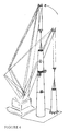
- Fig. 3 - Diagram of the placing of a segment on the support bases (5) for the pre-assembly of a section, coupling to the crown hoist bolts (10) and thee lower bolts (13), in a structure and procedure for erecting concrete towers used in wind turbines.
- Fig. 4 -Diagram of the erection of sections (4), with horizontal joints (15) in a structure and procedure for erecting concrete towers used in wind turbines.
- Fig. 5 - Diagram of hoisting from the lorry of the crown section with the belt (6) and the hook (7) for the coupling of the lower section and coupling elements (14) in the crown in a structure and procedure for erection of concrete towers used in wind turbines.
- Fig. 6 - Diagram of the positioning of a segment on the support base (5) with the transmitter (16) of the vertical laser beam (19) and the target (17) fixed on a light structure (18) in a structure and procedure for erecting concrete towers used in wind turbines.
- Fig 7.- Diagram of positioning of a section of the transmitter (16) of the vertical laser beam (19) and the Diana (17) fixed to a light structure (18) in a structure and procedure for erecting concrete towers used in wind turbines.
- According to the example of execution represented, the procedure for erecting concrete towers used in wind turbines illustrated in this preferential form of realisation consists basically of various stages or phases which may be developed at the same time on a parallel basis with the various towers in a wind farm, thus making optimum logistical use of the resources, materials and times necessary for assembly.
- The aforementioned procedure includes two different cycles of activity which may be developed alongside each other: the pre-assembly cycle and the erection cycle. In the example of realisation illustrated, both cycles have the same productive capacity: two towers per week. The pre-assembly cycle begins its activities some weeks beforehand, so that there is always a minimum advantage of having various towers in the erection cycle, thus avoiding interference of one over another.
- Each section (4) of the tower structure may be composed of different number of segments (1) based on their position in the height of the tower. Thus, in this example, an 80 metre high tower, the first section (0-20) corresponding to the first twenty metres of height of the tower is made up of four segments, each limited by vertical sections (8) of that section of tower. The second section (20-40) between twenty and forty metres of the tower height, is composed of three segments, as well as the third section (40-60) that is, at a height of forty to sixty metres of the tower height which is also composed of three segments. The fourth section (60-80) however, comprises two segments which come already pre-assembled in the factory in one single part.
- The aforementioned pre-assembly for each section consists of a procedure divided into the following phases, for each section comprising different segments: one phase for transport and erection of each segment, therefore there are as many phases as there are number of segments, followed by a final filling stage of the vertical joints (8) of each section.
- Thus, in the present example of realisation the pre-assembly of the first section (0-20) will be carried out in six stages, one comprising the arrival and assembly of each of the four segments, a fifth phase for filling the horizontal joint with the base footing and a sixth phase of filling the vertical joints, whereas the two following sections (20-40) and (40-60) shall be erected in four phases each, three for the arrival and erection of each segment and a fourth for filling the vertical joints.
- The pre-assembly of the first section can be directly carried out on the base footing or foundation of the wind turbine, while the other intermediate sections shall be erected on mounting bases (5), which may be placed on the ground in the zone of the platforms provided in the proximity of the base of each wind turbine, or on the base itself in a position next to the tower.
- Therefore, the aforementioned cycle of erection, is initiated following the first pre-assembly cycle in the same wind turbine, and consists of the placing of each section on the previous one; in this case, the placing of three sections each 20 metres high. In this operation each section is hoisted with the aid of a crane.
- Therefore, the pre-assembly cycle is begun with erection of the segments of the first section of the present structure of each concrete tower for wind turbines, which in this preferential form of realisation comprise the 20 first metres of the tower. The structure of the aforementioned first section comprises four segments (1) in the form of a section of the trunk of a straight or curved generator cone provided with hoisting bolts (10) enabling them to be mounted directly onto the definitive foundation. Thus the pre-assembly of the first section of each tower comprises the following stages:
- 1. Verification of the geometry, levelling and implements of the foundations and the prior placing of the levelling plates with the preadjusted thickness for obtaining levelling of the part. The initial thickness of the plates is 20 mm.
- 2. The segments are transported and arrive at the site and are not stored at the wind farm but are placed directly from the lorry onto the foundation (or on the pre-assembly bases in the case of the segments in sections 2 and 3).
- 3. In the lorry the first segment is coupled by the hoisting crown bolts to the erection crane and by the lower bolts (13) to another retention crane or to a second pulley tackle of the erection crane.
- 4. The segment is turned in the air ensuring that the protruding lower bars (9) (of the attachment to the base footing) do not collide or are damaged or bent. Having achieved the vertical position, the lower retaining bolts (13) are released and the segment hangs solely from just the crown bolts (10). The segment is then placed upright in its final location.
- 5. The segment is lowered placing the connection bars in their jacketing. As the segment is lowered the strut is activated (2) in order to adjust the end of the perforated plate of the foundation.
- 6. The position of the segment is checked. This is adjusted using the strut or the crane, increasing or reducing thickness of the levelling plates if necessary.
- 7. The operation is repeated with the diametrically opposed segment.
- 8. Erect the third segment, connecting it to the two segments already fitted by means of mechanical jacks (3) located in the vertical joints. With the segment at the appropriate height, tighten the jacks and check the opening of both vertical joints (8) along their height. The segment position is checked and the crane is released.
- 9. The fourth closing segment is erected by attaching it to the two first segments using the same procedure as with the third segment.
- 10. Having erected the 4_ segments, the overall position is checked once more and any necessary adjustments made
- 11. The grills of the vertical joints are introduced from the upper end
- 12. The 2 struts (2) are removed using the crane at the upper part of the section and any other elements required are introduced using the crane.
- 13. Formwork is laid around the horizontal joint of the base footing using a 5 cm high frame outside and inside the segments, separating their faces at a distance of 5 cm, the non-retractile mortar is then poured.
- 14. Previously, after or simultaneous to the pouring of the mortar for the lower horizontal joint, the mortar is poured in the vertical joints.
- 15. Having achieved sufficient resistance in the mortar of the vertical joints, the jacks (3) of the vertical joints are removed.
- The procedure continues with the pre-assembly of sections 2 (20 -40 m) and 3 (40-60 m).
- The procedure is similar to that of erection of the first section except that it is carried out on provisional foundation using (5) pre-assembly bases and with the following differences:
- The first segment erected is provided with a cross bracing support (2) in order to guarantee its provisional stability.
- For the second segment it is necessary to tighten the jacks (3) of the vertical joint.
- The erection of the third closing segment is similar to the closing segments of the first section.
- The lower horizontal joint will not be concreted.
- Below the procedure for erecting the concrete towers used in wind turbines continues with the erection of the sections (4) pursuant to the following stages:
- 1. Placement of levelling plates on the crown of the first section.
- 2. Placement round the edge of a profile of self-adhesive foam, tangential to the external edge of the surface of the crown of
section 1°, and a profile with an L shaped section which serves as internal formwork. - 3. Coupling of the crane to the crown bolts (10) of the second section, using slings.
- 4. Access to the platform (12) of the previous section (the first). Lifting of the second already pre-assembled section, and placement in its final location.
- 5. Lowering of the section, introducing the protruding reinforcement (9) into the jacketing (11) of the first section until it rests on the levelling plates.
- 6. Checking of the level of the second section. Correction of the position, if necessary acting on the thickness of the steel plates, while suspending the section with the crane.
- 7. Access to the upper platform (12) of the second section in order to uncouple the crane.
- This procedure is repeated for the third section.
- Erection of the fourth section, according to the following stages:
- 1. The fourth section is pre-assembled in the factory, on a lorry. Using slings the erection crane is coupled by 2 metal coupling elements (14) which are screwed to the section crown. Another retaining crane or other pulley tackle from the same crane will hook onto a belt (6) surrounding the section at approximately one metre from the lower end and which passes through a hook (7) which holds the lower rib of the section and stops the belt from slipping in the turning operation.
- 2. The fourth section is raised approximately one metre and the transport vehicle is removed.
- 3. The section is then turned by lifting the upper end with the erection crane while the crane, or 2nd pulley tackle retaining it holds the lower end at sufficient height to ensure that the protruding bars (9) do not hit the ground.
- 4. Having achieved a vertical position, the crane or 2nd retaining pulley tackle releases the load, transferring the full load to the erection crane. The belt and the coupling from the lower end are removed.
- 5. The fourth section is located on top of the third section and a similar procedure is followed for placing the second and third sections in their final position. In order to realise the horizontal joints (15) where the system for joining the horizontal joints is by fitting passive bars (9) in jacketing (11) with connective mortar, the following stages will be followed:
- 1. The non-retractile mortar is produced using a special mixer with a dosage specified according to the manufacturer instructions.
- 2. Firstly, all the jacketing of each joint are filled, checking the volume of the mortar introduced. There are openings in the head of all the jacketing in order to facilitate this operation.
- 3. Following controlled filling of the jacketing, the mortar is poured, filling the space of the horizontal joint (15) between sections.
- Finally, the form materials and dimensions and number of parts may vary, and in general anything which is an accessory or secondary may be employed provided that it does not alter, change or essentially modify the improvements described herein.
Claims (9)
- Structure and procedure for erecting concrete towers used in wind turbines basically consisting of a procedure for erection of concrete towers in different stages or phases, which may develop on a parallel basis in time in the different towers of a wind farm, including erection and pre-assembly activities of the sections (4) for each tower of wind turbine, in which each section of the structure of the towers may be composed of a number of different segments (1), or longitudinal sections based on their position in the height of the tower, characterised in that the fact that the procedure includes two differentiated cycles, which may be developed along parallel lines: that is, a pre-assembly of each tower section and erection of these ones, making the best logistic use of resources, materials and necessary erection times; with the pre-assembly cycle including a procedure divided into the following stages, for each section comprising various segments: a phase for transport and erection of each segment(1), therefore, having as many phases as the number of segments, followed by a final phase of filling of the vertical joints (8) of each section, and the erection cycle including a procedure for placing the pre-assembled sections (4), on top of each other until the complete tower is formed.
- Structure and procedure for erecting concrete towers used in wind turbines, according to claim 1, characterised in that the aforementioned pre-assembly cycle may be realised for the first section of the wind turbine tower directly on the base footing or foundation of the wind turbine, while the other intermediate sections are pre-assembled on mounting bases (5) which are placed on the ground in the area of the platforms provided in the proximity of the base footing of each wind turbine or, on the base itself, the segments being placed in their position with the aid of bracing and stabilising struts (2) and connection jacks (3) along the vertical joints.
- Structure and erection procedure of concrete towers for wind turbines, according to at least one of the previous claims, characterised in that the erection cycle, is initiated following the pre-assembly cycle, in the same wind turbine, and consists of placing each section (4) by hoisting with the aid of a crane and adjustment of the connection system of the horizontal joints (15) which may consist of fitting the passive reinforcement (9) protruding from the upper section into jacketing (11) for this purpose in the crown of the lower section.
- Structure and erection procedure for concrete towers used in wind turbines, according to at least one of the previous claims, characterised in that the final section may be pre-assembled in the factory, and erected on the previous section directly from the transport vehicle without previous storage, proceeding to turn the section from the horizontal position to the vertical one by coupling in the lower end gripping the perimeter of the section with nylon belt or the like fixed to the lower edge of the section using a metal hook, to prevent slipping.
- Structure and erection procedure of concrete towers for wind turbines, according to at least one of the previous claims, characterised in that the pre-assembly and erection cycles culminate with the execution of the vertical (8) or horizontal (15) joints by means of the appropriate pouring of non-retractile mortar which, together with the corresponding reinforcement achieves unified solidness of the tower overall, achieving effective connection between the different segments and sections.
- Structure and procedure for erecting concrete towers used in wind turbines, according to at least one of the previous claims, characterised in that the verification of the correct position of the segments and of the sections in the pre-assembly procedure in the erection is made by means of a transmitter (16) of vertical laser beam (19) which is self levelling placed on the axis of the section (for pre-assembly) or a permanent axis of the tower (in the assembly), close to the ground, and a target (17) fixed to each segment or section, in the axis of the section or tower, using an additional light structure (18), close to the crown, so that the deviation of the laser point with respect to the centre of the target provides the requisite indication for wedging the element and rectifying its position until the correct situation is reached.
- Structure and erection procedure of concrete towers for wind turbine, according to at least one of the previous claims, characterised in that the provisional stability of the 2 first segments in the pre-assembly of each section is achieved using a strut (2) which can be adjusted in length, which fixes the point of the segment to which it is anchored to a point in the earth or the base by joining it to a metal perforated plate previously placed for this purpose.
- Structure and erection procedure for concrete towers used in wind turbines, according to at least one of the previous claims, characterised in that the provisional union between each 2 segments along the vertical joints is achieved by means of a certain number of mechanical jacks (3) (preferably 3) which are fixed to each one of 2 perforated plates, one on each segment at both sides of the joint (8) at different heights and which, in addition to bracing the various segments of a section, serve to regulate the width of the joint (8) between the segments (separation of the alignments of the edge). When the jacks (3) for all the joints in a section are placed and adjusted, the provisional strut (2) may be removed. When the mortar for filling the vertical joints reaches the appropriate resistance, the mechanical jacks (3) may be removed.
- Structure and erection procedure for concrete towers used in wind turbines, according to at least one of the previous claims, characterised in that in the case of horizontal joints, the connection system is by means of various bars with non retractile mortar filling, the jackets have enlarged mouths to facilitate the reception of the mortar pouring, the external formwork for the horizontal joint made with a profile of self adhesive foam, tangential to the external edge of the surface crown of the lower section which is trapped between the sections, achieving the lower formwork with an L-shaped profile or a tubular or U-shape etc. approximately 5 cm high, located on the surface of the crown of the lower section at approximately 5 cm towards the interior of the internal surface of the upper section.
Priority Applications (2)
| Application Number | Priority Date | Filing Date | Title |
|---|---|---|---|
| PL06027134T PL1889988T3 (en) | 2006-08-16 | 2006-11-08 | Assembly structure and procedure for concrete towers used in wind turbines |
| EP13193900.1A EP2700771B1 (en) | 2006-08-16 | 2006-11-08 | Assembly structure and procedure for concrete tower used in wind turbines |
Applications Claiming Priority (1)
| Application Number | Priority Date | Filing Date | Title |
|---|---|---|---|
| ES200602204A ES2326010B2 (en) | 2006-08-16 | 2006-08-16 | STRUCTURE AND PROCEDURE FOR ASSEMBLING CONCRETE TOWERS FOR WIND TURBINES. |
Related Child Applications (2)
| Application Number | Title | Priority Date | Filing Date |
|---|---|---|---|
| EP13193900.1A Division EP2700771B1 (en) | 2006-08-16 | 2006-11-08 | Assembly structure and procedure for concrete tower used in wind turbines |
| EP13193900.1A Division-Into EP2700771B1 (en) | 2006-08-16 | 2006-11-08 | Assembly structure and procedure for concrete tower used in wind turbines |
Publications (3)
| Publication Number | Publication Date |
|---|---|
| EP1889988A2 true EP1889988A2 (en) | 2008-02-20 |
| EP1889988A3 EP1889988A3 (en) | 2011-03-09 |
| EP1889988B1 EP1889988B1 (en) | 2015-07-22 |
Family
ID=38659263
Family Applications (2)
| Application Number | Title | Priority Date | Filing Date |
|---|---|---|---|
| EP13193900.1A Active EP2700771B1 (en) | 2006-08-16 | 2006-11-08 | Assembly structure and procedure for concrete tower used in wind turbines |
| EP06027134.3A Active EP1889988B1 (en) | 2006-08-16 | 2006-11-08 | Assembly structure and procedure for concrete towers used in wind turbines |
Family Applications Before (1)
| Application Number | Title | Priority Date | Filing Date |
|---|---|---|---|
| EP13193900.1A Active EP2700771B1 (en) | 2006-08-16 | 2006-11-08 | Assembly structure and procedure for concrete tower used in wind turbines |
Country Status (10)
| Country | Link |
|---|---|
| US (2) | US7765766B2 (en) |
| EP (2) | EP2700771B1 (en) |
| CN (1) | CN100590280C (en) |
| AU (1) | AU2006241292B2 (en) |
| CA (2) | CA2567859C (en) |
| CL (1) | CL2006003095A1 (en) |
| ES (3) | ES2326010B2 (en) |
| MX (1) | MX2007001360A (en) |
| PL (1) | PL1889988T3 (en) |
| TR (1) | TR201903890T4 (en) |
Cited By (12)
| Publication number | Priority date | Publication date | Assignee | Title |
|---|---|---|---|---|
| WO2011029965A1 (en) * | 2009-09-09 | 2011-03-17 | Prefabricados Agricolas E Industriales, S. A. | Method for assembling a prefabricated concrete tower of a wind turbine and structure for the pre-assembly of the tower segments |
| WO2011083355A1 (en) * | 2010-01-05 | 2011-07-14 | Muhammad Yaqub | Method for erecting a tower for a wind turbine generator |
| WO2011092235A3 (en) * | 2010-01-27 | 2012-01-19 | Wobben, Aloys | Wind power plant and wind power plant tower segment |
| ES2398283R1 (en) * | 2011-08-12 | 2013-07-04 | Matis Hispania S A | USEFUL AND DOVELAS HANDLING PROCEDURE FORMING THE AEROGENERATOR TOWER SECTIONS |
| ES2396087R1 (en) * | 2011-06-30 | 2013-07-19 | Acciona Windpower Sa | ASSEMBLY PROCEDURE OF AN AIRCRAFT AND AEROGENERATOR ASSEMBLED ACCORDING TO THIS PROCEDURE |
| US8615965B2 (en) | 2009-09-15 | 2013-12-31 | Andresen Towers A/S | Tubular building structure with hingedly connected platform segment |
| WO2014067884A1 (en) * | 2012-10-30 | 2014-05-08 | Technische Universität Wien | Method for producing a tower construction from reinforced concrete |
| EP2937494A1 (en) * | 2014-04-25 | 2015-10-28 | Fullmann, Robert | Segment with a semi-finished product for the assembly of a wind power tower |
| EP2980337A1 (en) * | 2014-07-30 | 2016-02-03 | Acciona Windpower S.a. | Method for assembling diminishing section concrete towers for wind turbines and associated wind turbine |
| CN106223707A (en) * | 2016-07-18 | 2016-12-14 | 安徽状元郎电子科技有限公司 | A kind of electric pole of the convenient Anti-inclining installed |
| EP3246493A1 (en) | 2016-05-17 | 2017-11-22 | Holcim Technology Ltd. | A method for construction of a mast for a windmill |
| US20230183995A1 (en) * | 2020-08-04 | 2023-06-15 | Evaptech, Inc. | Cooling Tower Fan Cylinder |
Families Citing this family (74)
| Publication number | Priority date | Publication date | Assignee | Title |
|---|---|---|---|---|
| ES2246734B1 (en) * | 2005-04-21 | 2007-04-16 | STRUCTURAL CONCRETE & STEEL, S.L. | PREFABRICATED MODULAR TOWER. |
| KR100806661B1 (en) * | 2007-01-11 | 2008-02-26 | 서동택 | Installation method of onshore wind power generator using induction rail |
| DE202007003842U1 (en) * | 2007-03-15 | 2007-05-24 | Mecal Applied Mechanics B.V. | Mast for wind turbine has at least curved sections of prefabricated wall parts in different annular mast sections that are identical, at least in cross-section |
| WO2009056898A1 (en) * | 2007-11-02 | 2009-05-07 | Alejandro Cortina-Cordero | Post-tensioned concrete tower for wind turbines |
| FR2923504B1 (en) * | 2007-11-09 | 2010-02-12 | Freyssinet | METHOD FOR CONSTRUCTING A CIVIL WORK AND ASSOCIATED SYSTEM |
| US8734705B2 (en) | 2008-06-13 | 2014-05-27 | Tindall Corporation | Method for fabrication of structures used in construction of tower base supports |
| NZ589882A (en) * | 2008-07-15 | 2013-03-28 | Siemens Ag | Method for the assembly of a tower and tower made of vertically stacked precast elements held in place by tensioned cables running inside the tower |
| US20100024311A1 (en) * | 2008-07-30 | 2010-02-04 | Dustin Jon Wambeke | Wind turbine assembly with tower mount |
| US8555600B2 (en) * | 2008-12-10 | 2013-10-15 | Cortina Innovations, S.A. De C.V. | Method for mounting in sections an annular tower for wind power generator, heliostatic power generator or chimney composed from three concrete segments or more |
| SE534051C2 (en) * | 2009-02-27 | 2011-04-12 | Roger Ericsson | Prefabricated wall element for tower construction, as well as tower construction |
| US8281546B2 (en) * | 2009-05-05 | 2012-10-09 | Thompson Bradley D | Slip formed concrete wind turbine tower |
| PT2253782E (en) * | 2009-05-19 | 2013-11-18 | Pacadar Sa | Support structure for a wind turbine |
| US8511013B2 (en) * | 2009-09-03 | 2013-08-20 | General Electric Company | Wind turbine tower and system and method for fabricating the same |
| US8061964B2 (en) | 2009-09-05 | 2011-11-22 | Michael Zuteck | Hybrid multi-element tapered rotating tower |
| CA2770886C (en) * | 2009-09-09 | 2014-07-08 | National Oilwell Varco, L.P. | Method and apparatus for wind turbine erection |
| US8801330B2 (en) * | 2009-09-10 | 2014-08-12 | National Oilwell Varco, L.P. | Windmill installation system and method for using same |
| IT1396433B1 (en) * | 2009-11-16 | 2012-11-23 | Rolic Invest Sarl | WIND POWER PLANT FOR THE GENERATION OF ELECTRICITY AND METHOD TO REALIZE A PILONE OF THE ABOVE WIND FACILITY. |
| ES2595231T3 (en) | 2010-04-06 | 2016-12-28 | Soletanche Freyssinet | Hybrid tower construction method for a wind generator |
| NL2004987C2 (en) * | 2010-06-28 | 2011-12-29 | Ihc Holland Ie Bv | LIFT DEVICE AND METHOD FOR POSITIONING A LOG OBJECT. |
| DE102010038311A1 (en) * | 2010-07-23 | 2012-01-26 | Aloys Wobben | Protective foot for a piece goods, in particular concrete tower segments |
| US8307593B2 (en) * | 2010-08-18 | 2012-11-13 | General Electric Company | Tower with adapter section |
| CN102713277A (en) * | 2010-08-24 | 2012-10-03 | 三菱重工业株式会社 | Wind turbine device and method for constructing tower for blade wheel |
| CA2773190A1 (en) * | 2011-04-11 | 2012-10-11 | Envision Energy (Denmark) Aps | Offshore wind turbine comprising a support system for interchangeable containers with a wave run-up deflector |
| US20110239564A1 (en) * | 2011-04-15 | 2011-10-06 | General Electric Company | Apparatus, Composite Section, and Method for On-Site Tower Formation |
| EP2525021B8 (en) * | 2011-05-16 | 2018-11-28 | GE Renewable Technologies Wind B.V. | Wind turbine tower supporting structure |
| US8245458B2 (en) | 2011-05-17 | 2012-08-21 | General Electric Company | Wind turbine with tower support system and associated method of construction |
| US8881485B2 (en) | 2011-05-23 | 2014-11-11 | Iowa State University Research Foundation, Inc. | Wind turbine tower system |
| US9016012B1 (en) * | 2011-05-23 | 2015-04-28 | Iowa State University Research Foundation, Inc. | Wind turbine tower system |
| ES2401787B2 (en) * | 2011-06-09 | 2014-01-21 | Inneo Torres, S.L. | MACHIHEMBRADO FIXING ASSEMBLY |
| DE102011079314A1 (en) * | 2011-07-18 | 2013-01-24 | Rolf J. Werner | Tower-shaped structure |
| ES2460392B1 (en) * | 2012-02-07 | 2015-07-21 | Inneo Torres, S.L. | STORAGE STRUCTURE OF CONSTRUCTION MODULES OF AIRPORT SUPPLIER TOWERS, PROCEDURE USING STRUCTURE AND INSTALLATION RESULTING FROM SUCH PROCEDURE |
| EP2834435A1 (en) * | 2012-04-04 | 2015-02-11 | Forida Development A/S | Wind turbine comprising a tower part of an ultra-high performance fiber reinforced composite |
| ES2435211B2 (en) | 2012-05-18 | 2014-12-12 | Structural Research, S.L. | Self-climbing telescopic crane and assembly procedure for precast concrete towers |
| ES2438626B1 (en) | 2012-10-01 | 2014-09-10 | Gestamp Hybrid Towers, S.L. | Support structure for wind turbines and mold to obtain such structures |
| CN105026750B (en) * | 2012-12-20 | 2018-04-27 | 维斯塔斯风力系统有限公司 | Wind turbine tower guides the installation method of system and installation unit |
| ES2471641B1 (en) * | 2012-12-21 | 2015-04-07 | Acciona Windpower, S.A. | Prefabricated concrete dovela, wind turbine tower comprising said dovela, wind turbine comprising said tower and assembly procedure of said wind turbine |
| EP2781673B1 (en) * | 2013-03-21 | 2016-03-16 | ALSTOM Renewable Technologies | Tower |
| DE102013213976A1 (en) * | 2013-07-17 | 2015-01-22 | Wobben Properties Gmbh | A method of manufacturing a precast concrete segment of a wind turbine tower |
| PL2846040T3 (en) * | 2013-09-06 | 2018-09-28 | youWINenergy GmbH | Tower assembly for a wind turbine installation |
| ES2538734B1 (en) | 2013-12-20 | 2016-05-10 | Acciona Windpower, S.A. | Assembly procedure of concrete towers with a truncated cone section and a concrete tower mounted with said procedure |
| ES2545038B1 (en) * | 2014-03-07 | 2016-04-26 | Inneo Torres, S.L. | Construction system for wind towers |
| CN103939298B (en) * | 2014-04-01 | 2016-04-13 | 北京金风科创风电设备有限公司 | Structure for assembling concrete tower |
| AU2015246404B2 (en) * | 2014-04-14 | 2018-03-29 | Vestas Wind Systems A/S | Tower segment |
| US11536045B2 (en) * | 2014-10-30 | 2022-12-27 | Byo Towers, S.L. | Method for installing a hollow concrete tower made from more than one segment and corresponding hollow concrete tower |
| EP3212862B1 (en) * | 2014-10-31 | 2019-04-24 | Soletanche Freyssinet | Method for manufacturing concrete construction blocks for a wind-turbine tower and associated system |
| FR3029231B1 (en) * | 2014-12-01 | 2016-12-30 | Lafarge Sa | CONCRETE SECTION |
| DK3034870T3 (en) * | 2014-12-15 | 2022-09-05 | Nordex Energy Spain S A | WINDMILL WITH CONCRETE TOWER AND PROCEDURE FOR ASSEMBLY OF WINDMILL WITH CONCRETE TOWER |
| MX2017008938A (en) * | 2015-01-09 | 2018-05-17 | Tindall Corp | Tower and method for constructing a tower. |
| US9650840B2 (en) | 2015-04-27 | 2017-05-16 | National Oilwell Varco, L.P. | Method and apparatus for erecting a drilling rig |
| US20160348391A1 (en) * | 2015-05-29 | 2016-12-01 | Tindall Corporation | Method and apparatus for constructing a concrete tower |
| MX395363B (en) * | 2015-08-31 | 2025-03-25 | Siemens Gamesa Renewable Energy Inc | TOWER SEGMENT AND METHOD USING SEGMENTED SUPPORT PLATE. |
| US9657495B2 (en) * | 2015-10-14 | 2017-05-23 | James D. Lockwood | Crane system incorporated into a tower |
| CN106948645B (en) * | 2015-11-13 | 2019-04-30 | 新昌县晋通机械有限公司 | Power grid utility pole erection tool vehicle and its construction method |
| DE102016002372A1 (en) * | 2016-02-19 | 2017-08-24 | Senvion Gmbh | Method for assembling a tubular tower segment |
| CN106150179B (en) * | 2016-08-10 | 2018-08-03 | 河北可耐特玻璃钢有限公司 | A kind of fiber glass reinforced plastic chimney splicing hoisting |
| US9982659B1 (en) * | 2017-02-03 | 2018-05-29 | General Electric Company | Methods for refurbishing wind turbines |
| ES2862343T3 (en) | 2017-07-10 | 2021-10-07 | Nordex Energy Spain S A | Pre-assembly slab system for wind turbine concrete tower and assembly procedure of a pre-assembly slab system for wind turbine concrete towers |
| CN107651583B (en) * | 2017-08-30 | 2019-07-19 | 武汉船用机械有限责任公司 | A kind of manufacturing method of ocean platform crane tower body |
| US20190292803A1 (en) * | 2018-03-26 | 2019-09-26 | General Electric Company | Additively manufactured tower structure and method of fabrication |
| DE102018108945A1 (en) * | 2018-04-16 | 2019-10-17 | Wobben Properties Gmbh | Method for erecting a wind turbine tower |
| US10570889B2 (en) | 2018-04-23 | 2020-02-25 | General Electric Company | Adaptor for wind turbine refurbishment and associated methods |
| US10988909B1 (en) | 2018-08-29 | 2021-04-27 | RCAM Technologies, Inc. | Additive manufacturing of support structures |
| WO2020068119A1 (en) | 2018-09-28 | 2020-04-02 | General Electric Company | Method for manufacturing a telescoping wind turbine tower structure |
| CN109057350A (en) * | 2018-09-30 | 2018-12-21 | 中铁六局集团广州工程有限公司 | Concrete casting device and casting system |
| US11231017B2 (en) | 2019-03-29 | 2022-01-25 | General Electric Company | System and method for the service and exchange of a yaw bearing for a machine head of a wind turbine |
| EP3973178B1 (en) | 2019-05-21 | 2024-04-24 | Vestas Wind Systems A/S | A method for erecting a wind turbine tower using stud bolts |
| CN110670590B (en) * | 2019-10-16 | 2024-10-01 | 河南二建集团钢结构有限公司 | Movable ground anchor for mounting conical section of steel structure cooling tower and construction method thereof |
| EP4375455A4 (en) | 2021-07-22 | 2025-06-04 | Windtechnic Engineering, S.L. | Concrete tower with multiple sections |
| ES2938008B2 (en) * | 2021-10-01 | 2024-04-16 | Esteyco S A | INSTALLATION PROCEDURE OF A TOWER AND TOWER INSTALLED WITH SUCH PROCEDURE |
| ES2942547B2 (en) | 2021-12-01 | 2026-04-06 | Esteyco S A | PROCEDURE FOR MANUFACTURING AND ASSEMBLING A PLURALITY OF TOWERS IN A WIND FARM |
| CN115045560A (en) * | 2022-06-23 | 2022-09-13 | 中建钢构工程有限公司 | Pre-assembly method of special-shaped high-rise steel structure |
| EP4481144A1 (en) * | 2023-06-23 | 2024-12-25 | Nordex Energy Spain, S.A.U. | Concrete segment of a section of a wind turbine tower, set of a concrete segment and heating means, concrete section, wind turbine, mould and method of assembling the wind turbine |
| CN116988507B (en) * | 2023-08-15 | 2025-12-02 | 中国电建集团西北勘测设计研究院有限公司 | Self-adjusting foundation device and tower modification method for power transmission and transformation engineering towers |
| CN117780564B (en) * | 2023-12-20 | 2026-02-06 | 中铁十五局集团上海新能源发展有限公司 | Super-high wind power tower construction method integrating laser radar and unmanned aerial vehicle |
Family Cites Families (56)
| Publication number | Priority date | Publication date | Assignee | Title |
|---|---|---|---|---|
| US1265966A (en) * | 1913-05-17 | 1918-05-14 | Canton Culvert & Silo Company | Silo. |
| FR515224A (en) * | 1920-05-06 | 1921-03-26 | Bastidon Et Potay | Construction process for high-rise reinforced concrete poles, using molded keystones, for the transmission of electrical energy |
| US2638188A (en) * | 1951-05-17 | 1953-05-12 | Jack C Corn | Windbreak and livestock shade |
| US2958983A (en) * | 1956-07-23 | 1960-11-08 | Vincent J Hoover | Concrete storage structure |
| US3030057A (en) * | 1960-02-24 | 1962-04-17 | Theodore M Wright | Mountings for picture frames or the like |
| US3471053A (en) * | 1968-03-04 | 1969-10-07 | Chicago Bridge & Iron Co | Liquid storage tank using metal ring band instead of thicker lower courses |
| US3935633A (en) * | 1974-04-16 | 1976-02-03 | Bunker Jack E | Tank fabrication process |
| DE2520717C2 (en) * | 1975-05-09 | 1977-02-03 | Hans Tax | PROCEDURE FOR ERECTING A TOWER CRANE |
| US4045929A (en) * | 1975-12-01 | 1977-09-06 | Gianfranco Velo Dalbrenta | Liquidtight tank made of prestressed reinforced concrete, particularly for purification plants |
| US4147009A (en) * | 1975-12-04 | 1979-04-03 | Watry C Nicholas | Precast panel building construction |
| US4272929A (en) * | 1979-08-23 | 1981-06-16 | Hanson Bror H | Tower and method of construction |
| US5038540A (en) * | 1981-11-20 | 1991-08-13 | Krautz Alfons O | Sectional smokestack |
| US4435242A (en) | 1981-11-26 | 1984-03-06 | Bristol Composite Materials Engineering Limited | Elongate structure |
| JPS5997862A (en) * | 1982-11-24 | 1984-06-05 | 株式会社日立製作所 | Part feeder |
| FR2539792B1 (en) * | 1983-01-26 | 1985-11-15 | Matiere Marcel | METHOD FOR CONSTRUCTING WATERPROOF STRUCTURES, SUCH AS TANKS |
| FR2589509B1 (en) * | 1985-10-31 | 1989-02-10 | Pierrel Guy | METHOD FOR CONSTRUCTING STRUCTURES, SUCH AS TANKS, SILOS, TOWERS, CHIMNEYS, HIGH-DUCTS AND COMPONENTS FOR IMPLEMENTING SAME |
| FR2652115B1 (en) * | 1989-09-18 | 1991-11-29 | Pierrel Guy | IMPROVEMENTS IN A PROCESS FOR CONSTRUCTING STRUCTURES, SUCH AS TANKS, SILOS, TOWERS, CHIMNEYS, HIGH CONDUITS AND COMPONENTS FOR ITS IMPLEMENTATION. |
| FR2658228B1 (en) | 1990-02-14 | 1992-06-05 | Lachize Claudius | PROCESS FOR CONSTRUCTING REINFORCED CONCRETE TANKS, PREFABRICATED ELEMENTS FOR IMPLEMENTING SAID METHOD AND MACHINE FOR PRODUCING THE SAME. |
| DE9303837U1 (en) * | 1993-03-16 | 1993-07-01 | Preh-Werke GmbH & Co KG, 8740 Bad Neustadt | Keyboard |
| JPH0790928A (en) * | 1993-09-21 | 1995-04-04 | Shimizu Corp | SRC pillar construction method |
| US5809729A (en) * | 1996-03-05 | 1998-09-22 | Elward Systems Corporation | Method and apparatus for wall construction |
| US5765333A (en) * | 1996-04-03 | 1998-06-16 | Cunningham; Dale W. | Unitized post and panel building system |
| AU717556B2 (en) * | 1996-07-17 | 2000-03-30 | Mose Monachino | A foundation element, methods for the construction of prefabricated structures including these elements, particularly prefabricated tunnels, and prefabricated structures made by these methods |
| US6282863B1 (en) * | 1998-07-02 | 2001-09-04 | Chicago Bridge And Iron | Scaffoldless tank erection method |
| US6705058B1 (en) * | 1999-02-12 | 2004-03-16 | Newmark International Inc. | Multiple-part pole |
| JP2000283019A (en) * | 1999-03-31 | 2000-10-10 | Pc Bridge Co Ltd | Concrete windmill support tower and its construction method |
| DE10033845A1 (en) * | 2000-07-12 | 2002-01-24 | Aloys Wobben | Pre-stressed concrete tower |
| JP2002083019A (en) | 2000-09-08 | 2002-03-22 | Hosei Kk | Use environment providing method by client-server system |
| US20020154114A1 (en) * | 2000-11-30 | 2002-10-24 | Christensen Thomas Kragh | Method and system for customising build-to-order products |
| US6782667B2 (en) * | 2000-12-05 | 2004-08-31 | Z-Tek, Llc | Tilt-up and telescopic support tower for large structures |
| US6443655B1 (en) * | 2001-04-21 | 2002-09-03 | Robert Bennett | Flood barrier |
| DE10226996B4 (en) * | 2001-10-09 | 2014-07-03 | Aloys Wobben | Method for creating a foundation, in particular for a tower of a wind energy plant |
| DK200200178A (en) * | 2002-02-06 | 2003-08-07 | Vestas Wind Sys As | Wind turbine tower suspension means |
| NL1019953C2 (en) * | 2002-02-12 | 2002-12-19 | Mecal Applied Mechanics B V | Prefabricated tower or mast, as well as a method for joining and / or re-tensioning segments that must form a single structure, as well as a method for building a tower or mast consisting of segments. |
| HUP0201136A2 (en) * | 2002-04-03 | 2004-04-28 | Meir Silber | Tower structure |
| JP4355949B2 (en) * | 2002-10-01 | 2009-11-04 | ゼネラル・エレクトリック・カンパニイ | Modular kit for wind turbine tower |
| US20040068948A1 (en) * | 2002-10-03 | 2004-04-15 | Wrass Lawrence J. | Fire/party wall system |
| US7162844B2 (en) * | 2003-01-09 | 2007-01-16 | Chicago Bridge & Iron Company | Use of partial precast panels for construction of concrete walls and shells |
| US20040182019A1 (en) * | 2003-01-17 | 2004-09-23 | Patrick Flynn | Panel raising apparatus and method of use |
| CA2519277C (en) * | 2003-03-19 | 2011-07-12 | Vestas Wind Systems A/S | Method of constructing large towers for wind turbines |
| ES2234392B1 (en) * | 2003-03-31 | 2006-10-16 | Manuel Torres Martinez | PROCESS FOR THE ASSEMBLY OF THE TOWER OF AN AEROGENERATOR AND TOWER BUILT ASI. |
| AT413042B (en) * | 2003-12-19 | 2005-10-15 | Rund Stahl Bau Gmbh & Co | INTERNAL SHIFTING SECTION FOR BUILDING A BUILDING SECTION |
| JP4708365B2 (en) * | 2004-02-04 | 2011-06-22 | タタ、スティール、アイモイデン、ベスローテン、フェンノートシャップ | Wind turbine tower, prefabricated metal wall parts for use in wind turbine tower, and method for constructing wind turbine tower |
| DE102004017006B4 (en) * | 2004-04-02 | 2012-03-29 | Aloys Wobben | Method of erecting a tower |
| ES1058539Y (en) * | 2004-10-11 | 2005-04-01 | Inneo21 S L | PERFECTED MODULAR TOWER STRUCTURE FOR WIND TURBINES AND OTHER APPLICATIONS. |
| CA2495596A1 (en) * | 2005-02-07 | 2006-08-07 | Resin Systems Inc. | Method of modular pole construction and modular pole assembly |
| US20060213145A1 (en) * | 2005-03-22 | 2006-09-28 | Haller Mark E | Lattice-skin hybrid tower |
| ES2246734B1 (en) * | 2005-04-21 | 2007-04-16 | STRUCTURAL CONCRETE & STEEL, S.L. | PREFABRICATED MODULAR TOWER. |
| ES1060629Y (en) * | 2005-06-20 | 2006-02-01 | Inneo21 S L | PERFECTED STRUCTURE OF JOINTS BETWEEN MODULAR TOWER PLATES FOR WIND TURBINES AND OTHER APPLICATIONS |
| EP1767729A1 (en) * | 2005-09-23 | 2007-03-28 | Sika Technology AG | Tower structure |
| US20070151089A1 (en) * | 2005-12-30 | 2007-07-05 | Promicom, Inc. | Tension positioning apparatus and method of use for manufacturing poles and columns |
| WO2009056898A1 (en) * | 2007-11-02 | 2009-05-07 | Alejandro Cortina-Cordero | Post-tensioned concrete tower for wind turbines |
| EP2207943B1 (en) * | 2007-10-09 | 2016-11-23 | Jeffrey O. Willis | Tower structure and method of assembling |
| US8047804B2 (en) * | 2007-12-27 | 2011-11-01 | General Electric Company | Wind tower and method of assembling the same |
| US20100132299A1 (en) * | 2008-12-02 | 2010-06-03 | General Electric Company | Wind turbine with improved tower and method of assembling same |
| DE102009013186B4 (en) * | 2008-12-19 | 2015-05-28 | Senvion Se | Tower of a wind turbine |
-
2006
- 2006-08-16 ES ES200602204A patent/ES2326010B2/en not_active Expired - Fee Related
- 2006-11-08 PL PL06027134T patent/PL1889988T3/en unknown
- 2006-11-08 TR TR2019/03890T patent/TR201903890T4/en unknown
- 2006-11-08 ES ES06027134.3T patent/ES2343451T3/en active Active
- 2006-11-08 ES ES13193900T patent/ES2718873T3/en active Active
- 2006-11-08 EP EP13193900.1A patent/EP2700771B1/en active Active
- 2006-11-08 EP EP06027134.3A patent/EP1889988B1/en active Active
- 2006-11-10 CA CA2567859A patent/CA2567859C/en active Active
- 2006-11-10 CA CA2855976A patent/CA2855976A1/en not_active Abandoned
- 2006-11-13 CL CL200603095A patent/CL2006003095A1/en unknown
- 2006-11-21 AU AU2006241292A patent/AU2006241292B2/en active Active
- 2006-12-29 CN CN200610172832A patent/CN100590280C/en not_active Expired - Fee Related
-
2007
- 2007-02-01 MX MX2007001360A patent/MX2007001360A/en active IP Right Grant
- 2007-07-26 US US11/881,665 patent/US7765766B2/en active Active
-
2010
- 2010-06-24 US US12/822,544 patent/US8381487B2/en active Active
Cited By (23)
| Publication number | Priority date | Publication date | Assignee | Title |
|---|---|---|---|---|
| WO2011029965A1 (en) * | 2009-09-09 | 2011-03-17 | Prefabricados Agricolas E Industriales, S. A. | Method for assembling a prefabricated concrete tower of a wind turbine and structure for the pre-assembly of the tower segments |
| US8615965B2 (en) | 2009-09-15 | 2013-12-31 | Andresen Towers A/S | Tubular building structure with hingedly connected platform segment |
| WO2011083355A1 (en) * | 2010-01-05 | 2011-07-14 | Muhammad Yaqub | Method for erecting a tower for a wind turbine generator |
| CN102859189A (en) * | 2010-01-27 | 2013-01-02 | 乌本普罗帕蒂斯有限公司 | Wind power plant and wind power plant tower segment |
| US8844237B2 (en) | 2010-01-27 | 2014-09-30 | Wobben Properties Gmbh | Wind power plant and wind power plant tower segment |
| WO2011092235A3 (en) * | 2010-01-27 | 2012-01-19 | Wobben, Aloys | Wind power plant and wind power plant tower segment |
| CN102859189B (en) * | 2010-01-27 | 2016-04-06 | 乌本普罗帕蒂斯有限公司 | Wind energy installations and tower sections for wind energy installations |
| ES2396087R1 (en) * | 2011-06-30 | 2013-07-19 | Acciona Windpower Sa | ASSEMBLY PROCEDURE OF AN AIRCRAFT AND AEROGENERATOR ASSEMBLED ACCORDING TO THIS PROCEDURE |
| US9359993B2 (en) | 2011-06-30 | 2016-06-07 | Acciona Windpower, S.A. | Wind turbine assembling method and wind turbine assembled according to said method |
| US10132296B2 (en) | 2011-06-30 | 2018-11-20 | Acciona Windpower, S.A. | Wind turbine assembling method and wind turbine assembled according to said method |
| ES2398283R1 (en) * | 2011-08-12 | 2013-07-04 | Matis Hispania S A | USEFUL AND DOVELAS HANDLING PROCEDURE FORMING THE AEROGENERATOR TOWER SECTIONS |
| WO2014067884A1 (en) * | 2012-10-30 | 2014-05-08 | Technische Universität Wien | Method for producing a tower construction from reinforced concrete |
| US9657494B2 (en) | 2012-10-30 | 2017-05-23 | Technische Universität Wien | Method for producing a tower construction from reinforced concrete |
| WO2015161919A3 (en) * | 2014-04-25 | 2016-01-21 | Robert Füllmann | Segment consisting of a semi-finished product, for producing a tower of a wind turbine and corresponding method for producing said tower |
| EP2937494A1 (en) * | 2014-04-25 | 2015-10-28 | Fullmann, Robert | Segment with a semi-finished product for the assembly of a wind power tower |
| US9637944B2 (en) | 2014-07-30 | 2017-05-02 | Acciona Windpower, S.A. | Method for assembling decreasing section concrete towers for wind turbines and associated wind turbines |
| EP2980337A1 (en) * | 2014-07-30 | 2016-02-03 | Acciona Windpower S.a. | Method for assembling diminishing section concrete towers for wind turbines and associated wind turbine |
| EP3246493A1 (en) | 2016-05-17 | 2017-11-22 | Holcim Technology Ltd. | A method for construction of a mast for a windmill |
| WO2017198689A1 (en) * | 2016-05-17 | 2017-11-23 | Holcim Technology Ltd | A method for construction of a mast for a windmill |
| CN106223707A (en) * | 2016-07-18 | 2016-12-14 | 安徽状元郎电子科技有限公司 | A kind of electric pole of the convenient Anti-inclining installed |
| US20230183995A1 (en) * | 2020-08-04 | 2023-06-15 | Evaptech, Inc. | Cooling Tower Fan Cylinder |
| EP4193028A4 (en) * | 2020-08-04 | 2024-10-02 | Evaptech, Inc. | COOLING TOWER FAN CYLINDER |
| US12168886B2 (en) * | 2020-08-04 | 2024-12-17 | Evaptech, Inc. | Cooling tower fan cylinder |
Also Published As
| Publication number | Publication date |
|---|---|
| ES2343451T1 (en) | 2010-08-02 |
| ES2343451T3 (en) | 2015-11-13 |
| EP2700771A2 (en) | 2014-02-26 |
| CA2567859C (en) | 2014-09-30 |
| PL1889988T3 (en) | 2016-03-31 |
| EP2700771B1 (en) | 2019-01-02 |
| ES2326010B2 (en) | 2011-02-18 |
| AU2006241292A1 (en) | 2008-03-06 |
| EP1889988A3 (en) | 2011-03-09 |
| MX2007001360A (en) | 2009-02-12 |
| CA2567859A1 (en) | 2008-02-16 |
| CL2006003095A1 (en) | 2008-06-20 |
| CA2855976A1 (en) | 2008-02-16 |
| US7765766B2 (en) | 2010-08-03 |
| TR201903890T4 (en) | 2019-04-22 |
| US8381487B2 (en) | 2013-02-26 |
| AU2006241292B2 (en) | 2013-08-29 |
| AU2006241292A9 (en) | 2008-03-13 |
| US20100257797A1 (en) | 2010-10-14 |
| CN100590280C (en) | 2010-02-17 |
| EP2700771A3 (en) | 2014-08-20 |
| EP1889988B1 (en) | 2015-07-22 |
| CN101126284A (en) | 2008-02-20 |
| US20080040983A1 (en) | 2008-02-21 |
| ES2326010A1 (en) | 2009-09-28 |
| ES2718873T3 (en) | 2019-07-05 |
Similar Documents
| Publication | Publication Date | Title |
|---|---|---|
| EP2700771B1 (en) | Assembly structure and procedure for concrete tower used in wind turbines | |
| CA2735625C (en) | Method of building a hybrid tower for a wind generator | |
| US8281546B2 (en) | Slip formed concrete wind turbine tower | |
| US20170114777A1 (en) | System and method of assembling a wind turbine | |
| US11072903B2 (en) | Equipment tower having a concrete plinth | |
| EP2541059A2 (en) | Footing for wind turbine towers | |
| CN223660831U (en) | A construction platform combining rock-embedded anchor bolts and warning light piles | |
| US20210071380A1 (en) | Method for building concrete foundations for lattice-type offshore structures, and foundations built using this method | |
| ES2959280T3 (en) | Procedure for erecting a tower with a multi-part tower section | |
| US10662639B2 (en) | Methods for erecting a wall panel proximate an outermost edge of a land parcel | |
| AU2011201502B8 (en) | Method of building a hybrid tower for a wind generator | |
| CN119640755A (en) | Mounting construction method for shaft type water inlet and outlet rectifying cone of pumped storage power station |
Legal Events
| Date | Code | Title | Description |
|---|---|---|---|
| PUAI | Public reference made under article 153(3) epc to a published international application that has entered the european phase |
Free format text: ORIGINAL CODE: 0009012 |
|
| 17P | Request for examination filed |
Effective date: 20061108 |
|
| AK | Designated contracting states |
Kind code of ref document: A2 Designated state(s): AT BE BG CH CY CZ DE DK EE ES FI FR GB GR HU IE IS IT LI LT LU LV MC NL PL PT RO SE SI SK TR |
|
| AX | Request for extension of the european patent |
Extension state: AL BA HR MK YU |
|
| PUAL | Search report despatched |
Free format text: ORIGINAL CODE: 0009013 |
|
| AK | Designated contracting states |
Kind code of ref document: A3 Designated state(s): AT BE BG CH CY CZ DE DK EE ES FI FR GB GR HU IE IS IT LI LT LU LV MC NL PL PT RO SE SI SK TR |
|
| AX | Request for extension of the european patent |
Extension state: AL BA HR MK RS |
|
| AKX | Designation fees paid |
Designated state(s): AT BE BG CH CY CZ DE DK EE ES FI FR GB GR HU IE IS IT LI LT LU LV MC NL PL PT RO SE SI SK TR |
|
| 17Q | First examination report despatched |
Effective date: 20111121 |
|
| GRAP | Despatch of communication of intention to grant a patent |
Free format text: ORIGINAL CODE: EPIDOSNIGR1 |
|
| INTG | Intention to grant announced |
Effective date: 20150327 |
|
| GRAS | Grant fee paid |
Free format text: ORIGINAL CODE: EPIDOSNIGR3 |
|
| GRAA | (expected) grant |
Free format text: ORIGINAL CODE: 0009210 |
|
| AK | Designated contracting states |
Kind code of ref document: B1 Designated state(s): AT BE BG CH CY CZ DE DK EE ES FI FR GB GR HU IE IS IT LI LT LU LV MC NL PL PT RO SE SI SK TR |
|
| REG | Reference to a national code |
Ref country code: GB Ref legal event code: FG4D |
|
| REG | Reference to a national code |
Ref country code: CH Ref legal event code: EP |
|
| REG | Reference to a national code |
Ref country code: IE Ref legal event code: FG4D |
|
| REG | Reference to a national code |
Ref country code: AT Ref legal event code: REF Ref document number: 738037 Country of ref document: AT Kind code of ref document: T Effective date: 20150815 |
|
| REG | Reference to a national code |
Ref country code: DE Ref legal event code: R096 Ref document number: 602006046031 Country of ref document: DE |
|
| REG | Reference to a national code |
Ref country code: SE Ref legal event code: TRGR |
|
| REG | Reference to a national code |
Ref country code: ES Ref legal event code: FG2A Ref document number: 2343451 Country of ref document: ES Kind code of ref document: T3 Effective date: 20151113 |
|
| REG | Reference to a national code |
Ref country code: FR Ref legal event code: PLFP Year of fee payment: 10 |
|
| REG | Reference to a national code |
Ref country code: AT Ref legal event code: MK05 Ref document number: 738037 Country of ref document: AT Kind code of ref document: T Effective date: 20150722 |
|
| REG | Reference to a national code |
Ref country code: LT Ref legal event code: MG4D |
|
| REG | Reference to a national code |
Ref country code: NL Ref legal event code: MP Effective date: 20150722 |
|
| PG25 | Lapsed in a contracting state [announced via postgrant information from national office to epo] |
Ref country code: LT Free format text: LAPSE BECAUSE OF FAILURE TO SUBMIT A TRANSLATION OF THE DESCRIPTION OR TO PAY THE FEE WITHIN THE PRESCRIBED TIME-LIMIT Effective date: 20150722 Ref country code: LV Free format text: LAPSE BECAUSE OF FAILURE TO SUBMIT A TRANSLATION OF THE DESCRIPTION OR TO PAY THE FEE WITHIN THE PRESCRIBED TIME-LIMIT Effective date: 20150722 |
|
| PG25 | Lapsed in a contracting state [announced via postgrant information from national office to epo] |
Ref country code: PT Free format text: LAPSE BECAUSE OF FAILURE TO SUBMIT A TRANSLATION OF THE DESCRIPTION OR TO PAY THE FEE WITHIN THE PRESCRIBED TIME-LIMIT Effective date: 20151123 Ref country code: AT Free format text: LAPSE BECAUSE OF FAILURE TO SUBMIT A TRANSLATION OF THE DESCRIPTION OR TO PAY THE FEE WITHIN THE PRESCRIBED TIME-LIMIT Effective date: 20150722 Ref country code: IS Free format text: LAPSE BECAUSE OF FAILURE TO SUBMIT A TRANSLATION OF THE DESCRIPTION OR TO PAY THE FEE WITHIN THE PRESCRIBED TIME-LIMIT Effective date: 20151122 |
|
| REG | Reference to a national code |
Ref country code: DE Ref legal event code: R026 Ref document number: 602006046031 Country of ref document: DE |
|
| PG25 | Lapsed in a contracting state [announced via postgrant information from national office to epo] |
Ref country code: DK Free format text: LAPSE BECAUSE OF FAILURE TO SUBMIT A TRANSLATION OF THE DESCRIPTION OR TO PAY THE FEE WITHIN THE PRESCRIBED TIME-LIMIT Effective date: 20150722 Ref country code: IT Free format text: LAPSE BECAUSE OF FAILURE TO SUBMIT A TRANSLATION OF THE DESCRIPTION OR TO PAY THE FEE WITHIN THE PRESCRIBED TIME-LIMIT Effective date: 20150722 Ref country code: EE Free format text: LAPSE BECAUSE OF FAILURE TO SUBMIT A TRANSLATION OF THE DESCRIPTION OR TO PAY THE FEE WITHIN THE PRESCRIBED TIME-LIMIT Effective date: 20150722 Ref country code: CZ Free format text: LAPSE BECAUSE OF FAILURE TO SUBMIT A TRANSLATION OF THE DESCRIPTION OR TO PAY THE FEE WITHIN THE PRESCRIBED TIME-LIMIT Effective date: 20150722 Ref country code: SK Free format text: LAPSE BECAUSE OF FAILURE TO SUBMIT A TRANSLATION OF THE DESCRIPTION OR TO PAY THE FEE WITHIN THE PRESCRIBED TIME-LIMIT Effective date: 20150722 |
|
| PLBI | Opposition filed |
Free format text: ORIGINAL CODE: 0009260 |
|
| PG25 | Lapsed in a contracting state [announced via postgrant information from national office to epo] |
Ref country code: RO Free format text: LAPSE BECAUSE OF FAILURE TO SUBMIT A TRANSLATION OF THE DESCRIPTION OR TO PAY THE FEE WITHIN THE PRESCRIBED TIME-LIMIT Effective date: 20150722 |
|
| PLAX | Notice of opposition and request to file observation + time limit sent |
Free format text: ORIGINAL CODE: EPIDOSNOBS2 |
|
| 26 | Opposition filed |
Opponent name: MAX BOEGL WIND AG Effective date: 20160422 |
|
| PG25 | Lapsed in a contracting state [announced via postgrant information from national office to epo] |
Ref country code: MC Free format text: LAPSE BECAUSE OF FAILURE TO SUBMIT A TRANSLATION OF THE DESCRIPTION OR TO PAY THE FEE WITHIN THE PRESCRIBED TIME-LIMIT Effective date: 20150722 Ref country code: LU Free format text: LAPSE BECAUSE OF FAILURE TO SUBMIT A TRANSLATION OF THE DESCRIPTION OR TO PAY THE FEE WITHIN THE PRESCRIBED TIME-LIMIT Effective date: 20151108 |
|
| REG | Reference to a national code |
Ref country code: CH Ref legal event code: PL |
|
| PLAF | Information modified related to communication of a notice of opposition and request to file observations + time limit |
Free format text: ORIGINAL CODE: EPIDOSCOBS2 |
|
| GBPC | Gb: european patent ceased through non-payment of renewal fee |
Effective date: 20151108 |
|
| PG25 | Lapsed in a contracting state [announced via postgrant information from national office to epo] |
Ref country code: LI Free format text: LAPSE BECAUSE OF NON-PAYMENT OF DUE FEES Effective date: 20151130 Ref country code: CH Free format text: LAPSE BECAUSE OF NON-PAYMENT OF DUE FEES Effective date: 20151130 |
|
| REG | Reference to a national code |
Ref country code: IE Ref legal event code: MM4A |
|
| PG25 | Lapsed in a contracting state [announced via postgrant information from national office to epo] |
Ref country code: SI Free format text: LAPSE BECAUSE OF FAILURE TO SUBMIT A TRANSLATION OF THE DESCRIPTION OR TO PAY THE FEE WITHIN THE PRESCRIBED TIME-LIMIT Effective date: 20150722 |
|
| PG25 | Lapsed in a contracting state [announced via postgrant information from national office to epo] |
Ref country code: IE Free format text: LAPSE BECAUSE OF NON-PAYMENT OF DUE FEES Effective date: 20151108 Ref country code: GB Free format text: LAPSE BECAUSE OF NON-PAYMENT OF DUE FEES Effective date: 20151108 |
|
| REG | Reference to a national code |
Ref country code: FR Ref legal event code: PLFP Year of fee payment: 11 |
|
| PLBB | Reply of patent proprietor to notice(s) of opposition received |
Free format text: ORIGINAL CODE: EPIDOSNOBS3 |
|
| PG25 | Lapsed in a contracting state [announced via postgrant information from national office to epo] |
Ref country code: BE Free format text: LAPSE BECAUSE OF FAILURE TO SUBMIT A TRANSLATION OF THE DESCRIPTION OR TO PAY THE FEE WITHIN THE PRESCRIBED TIME-LIMIT Effective date: 20150722 |
|
| PLBP | Opposition withdrawn |
Free format text: ORIGINAL CODE: 0009264 |
|
| PLBD | Termination of opposition procedure: decision despatched |
Free format text: ORIGINAL CODE: EPIDOSNOPC1 |
|
| REG | Reference to a national code |
Ref country code: DE Ref legal event code: R100 Ref document number: 602006046031 Country of ref document: DE |
|
| PG25 | Lapsed in a contracting state [announced via postgrant information from national office to epo] |
Ref country code: HU Free format text: LAPSE BECAUSE OF FAILURE TO SUBMIT A TRANSLATION OF THE DESCRIPTION OR TO PAY THE FEE WITHIN THE PRESCRIBED TIME-LIMIT; INVALID AB INITIO Effective date: 20061108 Ref country code: BG Free format text: LAPSE BECAUSE OF FAILURE TO SUBMIT A TRANSLATION OF THE DESCRIPTION OR TO PAY THE FEE WITHIN THE PRESCRIBED TIME-LIMIT Effective date: 20150722 |
|
| PG25 | Lapsed in a contracting state [announced via postgrant information from national office to epo] |
Ref country code: NL Free format text: LAPSE BECAUSE OF FAILURE TO SUBMIT A TRANSLATION OF THE DESCRIPTION OR TO PAY THE FEE WITHIN THE PRESCRIBED TIME-LIMIT Effective date: 20150722 Ref country code: CY Free format text: LAPSE BECAUSE OF FAILURE TO SUBMIT A TRANSLATION OF THE DESCRIPTION OR TO PAY THE FEE WITHIN THE PRESCRIBED TIME-LIMIT Effective date: 20150722 Ref country code: GR Free format text: LAPSE BECAUSE OF FAILURE TO SUBMIT A TRANSLATION OF THE DESCRIPTION OR TO PAY THE FEE WITHIN THE PRESCRIBED TIME-LIMIT Effective date: 20150722 |
|
| PLBM | Termination of opposition procedure: date of legal effect published |
Free format text: ORIGINAL CODE: 0009276 |
|
| STAA | Information on the status of an ep patent application or granted ep patent |
Free format text: STATUS: OPPOSITION PROCEDURE CLOSED |
|
| 27C | Opposition proceedings terminated |
Effective date: 20170331 |
|
| PG25 | Lapsed in a contracting state [announced via postgrant information from national office to epo] |
Ref country code: TR Free format text: LAPSE BECAUSE OF FAILURE TO SUBMIT A TRANSLATION OF THE DESCRIPTION OR TO PAY THE FEE WITHIN THE PRESCRIBED TIME-LIMIT Effective date: 20150722 |
|
| REG | Reference to a national code |
Ref country code: FR Ref legal event code: PLFP Year of fee payment: 12 |
|
| P01 | Opt-out of the competence of the unified patent court (upc) registered |
Effective date: 20230527 |
|
| PGFP | Annual fee paid to national office [announced via postgrant information from national office to epo] |
Ref country code: DE Payment date: 20251118 Year of fee payment: 20 |
|
| PGFP | Annual fee paid to national office [announced via postgrant information from national office to epo] |
Ref country code: FI Payment date: 20251118 Year of fee payment: 20 |
|
| PGFP | Annual fee paid to national office [announced via postgrant information from national office to epo] |
Ref country code: FR Payment date: 20251125 Year of fee payment: 20 |
|
| PGFP | Annual fee paid to national office [announced via postgrant information from national office to epo] |
Ref country code: SE Payment date: 20251119 Year of fee payment: 20 |
|
| PGFP | Annual fee paid to national office [announced via postgrant information from national office to epo] |
Ref country code: PL Payment date: 20251024 Year of fee payment: 20 |
|
| PGFP | Annual fee paid to national office [announced via postgrant information from national office to epo] |
Ref country code: ES Payment date: 20251216 Year of fee payment: 20 |