EP1890360A1 - Elektronischer Steckverbinder und Verfahren zu dessen Anbringung - Google Patents
Elektronischer Steckverbinder und Verfahren zu dessen Anbringung Download PDFInfo
- Publication number
- EP1890360A1 EP1890360A1 EP07075688A EP07075688A EP1890360A1 EP 1890360 A1 EP1890360 A1 EP 1890360A1 EP 07075688 A EP07075688 A EP 07075688A EP 07075688 A EP07075688 A EP 07075688A EP 1890360 A1 EP1890360 A1 EP 1890360A1
- Authority
- EP
- European Patent Office
- Prior art keywords
- electrical connector
- polymeric
- housing structure
- harness
- welding strip
- Prior art date
- Legal status (The legal status is an assumption and is not a legal conclusion. Google has not performed a legal analysis and makes no representation as to the accuracy of the status listed.)
- Granted
Links
Images
Classifications
-
- H—ELECTRICITY
- H01—ELECTRIC ELEMENTS
- H01R—ELECTRICALLY-CONDUCTIVE CONNECTIONS; STRUCTURAL ASSOCIATIONS OF A PLURALITY OF MUTUALLY-INSULATED ELECTRICAL CONNECTING ELEMENTS; COUPLING DEVICES; CURRENT COLLECTORS
- H01R4/00—Electrically-conductive connections between two or more conductive members in direct contact, i.e. touching one another; Means for effecting or maintaining such contact; Electrically-conductive connections having two or more spaced connecting locations for conductors and using contact members penetrating insulation
- H01R4/02—Soldered or welded connections
- H01R4/029—Welded connections
-
- H—ELECTRICITY
- H01—ELECTRIC ELEMENTS
- H01R—ELECTRICALLY-CONDUCTIVE CONNECTIONS; STRUCTURAL ASSOCIATIONS OF A PLURALITY OF MUTUALLY-INSULATED ELECTRICAL CONNECTING ELEMENTS; COUPLING DEVICES; CURRENT COLLECTORS
- H01R13/00—Details of coupling devices of the kinds covered by groups H01R12/70 or H01R24/00 - H01R33/00
- H01R13/46—Bases; Cases
- H01R13/502—Bases; Cases composed of different pieces
- H01R13/504—Bases; Cases composed of different pieces different pieces being moulded, cemented, welded, e.g. ultrasonic welding, or swaged together
-
- H—ELECTRICITY
- H01—ELECTRIC ELEMENTS
- H01R—ELECTRICALLY-CONDUCTIVE CONNECTIONS; STRUCTURAL ASSOCIATIONS OF A PLURALITY OF MUTUALLY-INSULATED ELECTRICAL CONNECTING ELEMENTS; COUPLING DEVICES; CURRENT COLLECTORS
- H01R13/00—Details of coupling devices of the kinds covered by groups H01R12/70 or H01R24/00 - H01R33/00
- H01R13/46—Bases; Cases
- H01R13/52—Dustproof, splashproof, drip-proof, waterproof, or flameproof cases
- H01R13/5202—Sealing means between parts of housing or between housing part and a wall, e.g. sealing rings
-
- H—ELECTRICITY
- H01—ELECTRIC ELEMENTS
- H01R—ELECTRICALLY-CONDUCTIVE CONNECTIONS; STRUCTURAL ASSOCIATIONS OF A PLURALITY OF MUTUALLY-INSULATED ELECTRICAL CONNECTING ELEMENTS; COUPLING DEVICES; CURRENT COLLECTORS
- H01R13/00—Details of coupling devices of the kinds covered by groups H01R12/70 or H01R24/00 - H01R33/00
- H01R13/46—Bases; Cases
- H01R13/533—Bases, cases made for use in extreme conditions, e.g. high temperature, radiation, vibration, corrosive environment, pressure
-
- H—ELECTRICITY
- H01—ELECTRIC ELEMENTS
- H01R—ELECTRICALLY-CONDUCTIVE CONNECTIONS; STRUCTURAL ASSOCIATIONS OF A PLURALITY OF MUTUALLY-INSULATED ELECTRICAL CONNECTING ELEMENTS; COUPLING DEVICES; CURRENT COLLECTORS
- H01R13/00—Details of coupling devices of the kinds covered by groups H01R12/70 or H01R24/00 - H01R33/00
- H01R13/73—Means for mounting coupling parts to apparatus or structures, e.g. to a wall
- H01R13/74—Means for mounting coupling parts in openings of a panel
-
- H—ELECTRICITY
- H01—ELECTRIC ELEMENTS
- H01R—ELECTRICALLY-CONDUCTIVE CONNECTIONS; STRUCTURAL ASSOCIATIONS OF A PLURALITY OF MUTUALLY-INSULATED ELECTRICAL CONNECTING ELEMENTS; COUPLING DEVICES; CURRENT COLLECTORS
- H01R2201/00—Connectors or connections adapted for particular applications
- H01R2201/26—Connectors or connections adapted for particular applications for vehicles
Definitions
- This invention relates to electrical connectors and more particularly to sealing attachment of an electrical connector to a metal structure.
- an electrical connector including a polymeric connector harness, at least one electrical conductor extending through the polymeric connector harness, and a welding strip sealingly connected around a perimeter of the polymeric connector harness to facilitate welding of the electrical connector to a housing structure to sealingly cover or fill an opening defined in the housing structure.
- an assembly including a housing structure defining an opening sealingly closed with an electrical connector.
- the electrical connector includes a polymeric connector harness, at least one electrical conductor extending through the polymeric connector harness, and a welding strip sealingly connected to and extending around a perimeter of the polymeric connector harness. A weld joint between the housing structure and the welding strip extends around the electrical connector to seal the electrical connector in the opening.
- a process for sealingly attaching an electrical connector to a housing structure includes providing an electrical connector including a polymeric connector harness, at least one electrical conductor extending through the polymeric connector harness, and a welding strip sealingly connected to and extending around a perimeter of the polymeric connector harness, positioning the electrical connector at an opening defined in a housing structure, and welding the welding strip to the housing structure to sealingly attach the electrical connector at the opening of the housing structure.
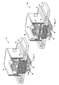
- FIG. 1 is a cross-sectional perspective view of an electrical connector in accordance with the invention welded to a housing structure to sealingly close an opening in the housing structure.
- FIG. 2 is a cross-sectional perspective view of an alternative embodiment of an electrical connector in accordance with the invention welded to a housing structure to sealingly close an opening defined in the housing structure, in which a welding strip is embedded within and extends substantially across an area of the polymeric electrical connector harness to provide electromagnetic impulse shielding.
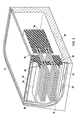
- FIG. 3 is a cross-sectional perspective view of an alternative embodiment of the invention in which the welding strip has a section with a flange that extends laterally away from the polymeric electrical connector harness and another section that is embedded flush with a sidewall of the polymeric electrical connector harness.
- FIG. 1 Shown in FIG. 1 is an assembly 10 including a housing structure 12, such as the bottom, top or sidewall of an enclosure or housing for an electrical or electronic component, and an electrical connector 16 sealingly closing an opening in housing structure 12 defined by edges 14.
- Connector 16 includes a polymeric connector harness 18, a plurality of electrical conductors 20 extending through polymeric connector harness 18, and a welding strip 22 sealingly connected to polymeric connector harness 18.
- Polymeric connector harness 18 can be molded or otherwise shaped from any of a variety of electrically insulative polymeric compositions comprising a thermoplastic polymer, such as a polyolefin (e.g., polypropylene), nylon, or the like, and optionally comprising non-polymeric additives, such as fillers, colorants, UV stabilizers, etc.
- Welding strip 22 can be a metal strip sealingly connected to polymeric connector harness 18 by embedding or insert-molding a portion, such as upstanding lip section 26 within polymeric connector harness 18.
- welding strip 22 may be a thermoplastic strip that is capable of being friction strip welded.
- thermoplastic welding strip 22 In the case of a thermoplastic welding strip 22, it can either be a separate component insert molded into connector 16, or an integral portion of connector 16 that is formed together with connector 16 in a single molding operation.
- Electrical conductors 20 can be embedded within polymeric connector harness 18 during an insert-molding process. Sizing agents (e.g., silane adhesion promoters such as aminopropyltrimethoxysilane) may be employed to promote adhesion and sealing engagement between polymeric connector harness 18 and the embedded portions of welding strip 22 and electrical conductors 20.
- Sizing agents e.g., silane adhesion promoters such as aminopropyltrimethoxysilane
- Housing structure 12 may be composed of any of a variety of weldable thermoplastics, metals, or meal alloys.
- housing structure 12 and welding strip 22 are comprised of metals or metal alloys, such as aluminum or an aluminum alloy.
- Welding strip 22 and housing structure 12 are joined together by a weld joint 24 that extends continuously around connector 16 and sealingly closes the opening defined in metal structure 12.
- electrical conductors 20 are pins designed to engage sockets of an electronic component on the inside of a housing on one side (with the portions extending downwardly from connector 16 in FIG. 1) and a socket connector on the other (top) side of connector 16.
- other types of conductors are envisioned, including electrical wires, socket connections, etc.
- welding strip 22 and housing structure 12 are joined and sealed together with a weld joint 24 that is produced by a friction stir welding technique.
- friction stir welding a tool with a probe attached to its tip is rotated at a high speed while being pushed against the overlapping (or abutting) pieces of metal to be welded. The frictional heat generated by this process softens the metal to produce a plastic flow that effectively stirs the overlapping (or abutting) metal pieces and melts the pieces together to create a weld.
- friction stir welding is a solid phase welding method that produces a weld joint having excellent mechanical properties. Friction stir welding has several advantages. First it creates a hermetic seal between the housing component and electrical harness.
- weld joints having excellent mechanical properties can be achieved between components composed of different metals or metal alloys, or between different thermoplastics.
- the strong and durable weld joint between welding strip 22 and housing structure 12 eliminates the need for mechanical fasteners such as threaded screws or the like. It also eliminates the need for dispensing adhesives and for curing adhesives, thereby reducing capital equipment and energy costs.
- Friction stir welding also produces a reliable weld joint that is not susceptible to failure, and which provides improved electromagnetic compatibility. In fact, the high reliability of the weld joint produced by friction stir welding is expected to eliminate the need for leak testing after assembly.
- FIG. 2 there is shown an alternative embodiment, in which welding strip 22 is part of a stamped metal piece that extends all the way through polymeric connector harness 18, but which is provided with apertures 30 to permit conductors 20 to pass through without contacting metal plate 32, and to allow the upper and lower sections of polymeric connector harness 18 to form a unitary mass during molding or other shaping operations.
- Metal plate 32 provides electromagnetic impulse shielding at a relatively low cost.
- FIG. 3 Shown in FIG. 3 is another example of the invention in which the opening in the housing structure is defined by a metal base housing component 40 and a metal cover housing component 42 that are welded together to define an opening for connector 50.
- Welding strip 52 includes a flanged section 54 that projects laterally away from polymeric connector harness 50, and another section 56 that is embedded flush with a wall of polymeric connector harness 50.
- Connector harness 50 is sealingly connected to the housing defined by base 40 and cover 42 by stir friction welding between the flanged section 54 of welding strip 52 and the underlying base housing component 40 along weld joint 60, and by stir friction welding between cover 42 and the flush mounted section 56 of welding strip 52 along weld joint 62.
- An electrical component 70 is disposed in the housing defined by components 40, 42 and connector 50, and is electrically connected to one or more other electrical devices by conductors 20.
- the electrical connectors, assemblies, and processes of this invention have advantages of creating a hermetic seal between a connector and a metal structure, eliminating the need for mechanical fasteners, eliminating the need for dispensing adhesives, reducing capital equipment and energy costs, enhancing product validation testing, and/or eliminating leak testing of components after assembly.
Landscapes
- Connector Housings Or Holding Contact Members (AREA)
- Coupling Device And Connection With Printed Circuit (AREA)
Applications Claiming Priority (1)
| Application Number | Priority Date | Filing Date | Title |
|---|---|---|---|
| US11/506,336 US7568932B2 (en) | 2006-08-18 | 2006-08-18 | Electronic connector and method of attachment |
Publications (2)
| Publication Number | Publication Date |
|---|---|
| EP1890360A1 true EP1890360A1 (de) | 2008-02-20 |
| EP1890360B1 EP1890360B1 (de) | 2009-10-14 |
Family
ID=38608791
Family Applications (1)
| Application Number | Title | Priority Date | Filing Date |
|---|---|---|---|
| EP07075688A Not-in-force EP1890360B1 (de) | 2006-08-18 | 2007-08-15 | Elektronischer Steckverbinder und Verfahren zu dessen Anbringung |
Country Status (4)
| Country | Link |
|---|---|
| US (1) | US7568932B2 (de) |
| EP (1) | EP1890360B1 (de) |
| AT (1) | ATE445921T1 (de) |
| DE (1) | DE602007002755D1 (de) |
Cited By (3)
| Publication number | Priority date | Publication date | Assignee | Title |
|---|---|---|---|---|
| GB2460620A (en) * | 2008-03-07 | 2009-12-09 | Otter Controls Ltd | Electrical appliances and components |
| EP2226185A4 (de) * | 2007-11-29 | 2011-08-31 | Ngk Spark Plug Co | Metall-harz-verbundglied |
| WO2017167785A1 (de) * | 2016-03-30 | 2017-10-05 | Molex Connectivity GmbH | Gedichtete elektrische steckverbinderanordnung |
Families Citing this family (12)
| Publication number | Priority date | Publication date | Assignee | Title |
|---|---|---|---|---|
| US8616522B2 (en) * | 2007-07-10 | 2013-12-31 | Continental Tire Canada, Inc. | Idle air control valve |
| DE102007048056A1 (de) * | 2007-10-05 | 2009-04-09 | Zf Friedrichshafen Ag | Durchführungsvorrichtung für elektrische und hydraulische Leitungen an einem Wasserfahrzeug |
| JP5077670B2 (ja) * | 2007-11-09 | 2012-11-21 | 住友電装株式会社 | 機器用コネクタ |
| DE102008020668A1 (de) * | 2008-04-24 | 2009-11-05 | Continental Automotive Gmbh | Steckverbindung zur Kontaktierung einer in einem Gehäuse angeordneten elektrischen Leiterplatte |
| US9033749B2 (en) | 2011-10-06 | 2015-05-19 | Fisher Controls International, Llc | Electrical terminal having a housing with a wire clamp to secure a wire to a connector pin |
| DE102013105518A1 (de) * | 2013-05-29 | 2014-12-04 | Escha Bauelemente Gmbh | Signalverteiler |
| US9754631B2 (en) * | 2015-09-02 | 2017-09-05 | Seagate Technology Llc | Disc drive apparatus with hermetically sealed cavity |
| JP6891479B2 (ja) * | 2016-12-20 | 2021-06-18 | 住友電装株式会社 | コネクタ |
| JP6217876B1 (ja) * | 2017-03-13 | 2017-10-25 | Smk株式会社 | 電気コネクタ及び電気コネクタの製造方法 |
| JP6230013B1 (ja) * | 2017-04-07 | 2017-11-15 | Smk株式会社 | 電気コネクタ |
| US20190067861A1 (en) * | 2017-08-28 | 2019-02-28 | Jf Microtechnology Sdn. Bhd. | Low inductance electrical contact assembly |
| JP2024120303A (ja) * | 2023-02-24 | 2024-09-05 | 住友電装株式会社 | コネクタ装置 |
Citations (4)
| Publication number | Priority date | Publication date | Assignee | Title |
|---|---|---|---|---|
| US4213004A (en) * | 1978-06-30 | 1980-07-15 | The United States Of America As Represented By The Secretary Of The Air Force | Hermetic electrical feedthrough for aluminum housing and method of making same |
| US20020046864A1 (en) * | 2000-04-28 | 2002-04-25 | Bellino Joseph P. | Method of joining conductive materials |
| WO2002058954A1 (de) * | 2001-01-25 | 2002-08-01 | Siemens Aktiengesellschaft | Einrichtung zur durchführung von elektrischen leitungen durch die wandung eines kraftstoffbehälters |
| WO2005091364A1 (en) * | 2004-03-20 | 2005-09-29 | Young Hwa Tech Co., Ltd. | Integrated electronic module structure for vehicles |
Family Cites Families (3)
| Publication number | Priority date | Publication date | Assignee | Title |
|---|---|---|---|---|
| US6017238A (en) * | 1998-06-09 | 2000-01-25 | The Wiremold Company | Connector assembly and method for making |
| WO2000049841A1 (de) * | 1999-02-18 | 2000-08-24 | Siemens Aktiengesellschaft | Elektrisches verbindungsverfahren und verbindungsstelle |
| DE10036900C2 (de) * | 2000-07-28 | 2002-07-11 | Siemens Ag | Verfahren zur Kontaktierung einer flexiblen Leiterplatte mit einem Kontaktpartner und Anordnung aus flexibler Leiterplatte und Kontaktpartner |
-
2006
- 2006-08-18 US US11/506,336 patent/US7568932B2/en active Active
-
2007
- 2007-08-15 EP EP07075688A patent/EP1890360B1/de not_active Not-in-force
- 2007-08-15 DE DE602007002755T patent/DE602007002755D1/de active Active
- 2007-08-15 AT AT07075688T patent/ATE445921T1/de not_active IP Right Cessation
Patent Citations (4)
| Publication number | Priority date | Publication date | Assignee | Title |
|---|---|---|---|---|
| US4213004A (en) * | 1978-06-30 | 1980-07-15 | The United States Of America As Represented By The Secretary Of The Air Force | Hermetic electrical feedthrough for aluminum housing and method of making same |
| US20020046864A1 (en) * | 2000-04-28 | 2002-04-25 | Bellino Joseph P. | Method of joining conductive materials |
| WO2002058954A1 (de) * | 2001-01-25 | 2002-08-01 | Siemens Aktiengesellschaft | Einrichtung zur durchführung von elektrischen leitungen durch die wandung eines kraftstoffbehälters |
| WO2005091364A1 (en) * | 2004-03-20 | 2005-09-29 | Young Hwa Tech Co., Ltd. | Integrated electronic module structure for vehicles |
Cited By (5)
| Publication number | Priority date | Publication date | Assignee | Title |
|---|---|---|---|---|
| EP2226185A4 (de) * | 2007-11-29 | 2011-08-31 | Ngk Spark Plug Co | Metall-harz-verbundglied |
| US8357015B2 (en) | 2007-11-29 | 2013-01-22 | Ngk Spark Plug Co., Ltd. | Metal-resin compound member |
| GB2460620A (en) * | 2008-03-07 | 2009-12-09 | Otter Controls Ltd | Electrical appliances and components |
| GB2460620B (en) * | 2008-03-07 | 2012-12-12 | Otter Controls Ltd | Electrical appliances and components |
| WO2017167785A1 (de) * | 2016-03-30 | 2017-10-05 | Molex Connectivity GmbH | Gedichtete elektrische steckverbinderanordnung |
Also Published As
| Publication number | Publication date |
|---|---|
| DE602007002755D1 (de) | 2009-11-26 |
| ATE445921T1 (de) | 2009-10-15 |
| EP1890360B1 (de) | 2009-10-14 |
| US20080045065A1 (en) | 2008-02-21 |
| US7568932B2 (en) | 2009-08-04 |
Similar Documents
| Publication | Publication Date | Title |
|---|---|---|
| EP1890360B1 (de) | Elektronischer Steckverbinder und Verfahren zu dessen Anbringung | |
| EP1898684A1 (de) | Versiegelte elektronische Komponente | |
| US8287219B2 (en) | Fastening arrangement | |
| US6552911B1 (en) | Electrical device | |
| JP5428722B2 (ja) | 電線の止水構造および該止水構造の形成方法 | |
| CN102683062B (zh) | 电动工具用触发开关 | |
| US10263362B2 (en) | Fluidically sealed enclosure for window electrical connections | |
| US7682204B2 (en) | Electrical apparatus and method of manufacturing the same | |
| US10522940B2 (en) | Method of manufacturing sealed electrical connector | |
| JP5789136B2 (ja) | 電気接続端子 | |
| KR20160023629A (ko) | 배터리 상태 검지 장치 및, 그의 제조 방법 | |
| JP2003234144A (ja) | コネクタ | |
| CN108808991B (zh) | 用于车窗调节器的水密组件 | |
| US10785881B2 (en) | Bonded electronic control unit | |
| CN208796747U (zh) | 一种电磁线圈装置 | |
| US7455552B1 (en) | Overmolded electronic assembly with metal seal ring | |
| CN1093732C (zh) | 柔韧密封件和其制造方法 | |
| KR20150046145A (ko) | 인버터 | |
| JP5075730B2 (ja) | シール部材保護キャップおよびコネクタ | |
| EP3726552A1 (de) | Abgedichtete elektrische schalteranordnung | |
| JP5099186B2 (ja) | 放電灯点灯装置 | |
| CN112703827B (zh) | 包括电源模块和保护设备的组件以及空调单元 | |
| JP2018037540A (ja) | 防塵カバー | |
| JP6498742B1 (ja) | 保護部品及び保護方法 | |
| KR102764388B1 (ko) | 방수씰이 구비된 직류 모터용 케이블 장치, 제조 방법 및 그 케이블 장치를 포함한 직류 모터 장치 |
Legal Events
| Date | Code | Title | Description |
|---|---|---|---|
| PUAI | Public reference made under article 153(3) epc to a published international application that has entered the european phase |
Free format text: ORIGINAL CODE: 0009012 |
|
| AK | Designated contracting states |
Kind code of ref document: A1 Designated state(s): AT BE BG CH CY CZ DE DK EE ES FI FR GB GR HU IE IS IT LI LT LU LV MC MT NL PL PT RO SE SI SK TR |
|
| AX | Request for extension of the european patent |
Extension state: AL BA HR MK YU |
|
| 17P | Request for examination filed |
Effective date: 20080820 |
|
| 17Q | First examination report despatched |
Effective date: 20080929 |
|
| AKX | Designation fees paid |
Designated state(s): AT BE BG CH CY CZ DE DK EE ES FI FR GB GR HU IE IS IT LI LT LU LV MC MT NL PL PT RO SE SI SK TR |
|
| GRAP | Despatch of communication of intention to grant a patent |
Free format text: ORIGINAL CODE: EPIDOSNIGR1 |
|
| GRAS | Grant fee paid |
Free format text: ORIGINAL CODE: EPIDOSNIGR3 |
|
| GRAA | (expected) grant |
Free format text: ORIGINAL CODE: 0009210 |
|
| AK | Designated contracting states |
Kind code of ref document: B1 Designated state(s): AT BE BG CH CY CZ DE DK EE ES FI FR GB GR HU IE IS IT LI LT LU LV MC MT NL PL PT RO SE SI SK TR |
|
| REG | Reference to a national code |
Ref country code: GB Ref legal event code: FG4D |
|
| REG | Reference to a national code |
Ref country code: CH Ref legal event code: EP |
|
| REG | Reference to a national code |
Ref country code: IE Ref legal event code: FG4D |
|
| REF | Corresponds to: |
Ref document number: 602007002755 Country of ref document: DE Date of ref document: 20091126 Kind code of ref document: P |
|
| LTIE | Lt: invalidation of european patent or patent extension |
Effective date: 20091014 |
|
| NLV1 | Nl: lapsed or annulled due to failure to fulfill the requirements of art. 29p and 29m of the patents act | ||
| PG25 | Lapsed in a contracting state [announced via postgrant information from national office to epo] |
Ref country code: IS Free format text: LAPSE BECAUSE OF FAILURE TO SUBMIT A TRANSLATION OF THE DESCRIPTION OR TO PAY THE FEE WITHIN THE PRESCRIBED TIME-LIMIT Effective date: 20100214 Ref country code: FI Free format text: LAPSE BECAUSE OF FAILURE TO SUBMIT A TRANSLATION OF THE DESCRIPTION OR TO PAY THE FEE WITHIN THE PRESCRIBED TIME-LIMIT Effective date: 20091014 Ref country code: PT Free format text: LAPSE BECAUSE OF FAILURE TO SUBMIT A TRANSLATION OF THE DESCRIPTION OR TO PAY THE FEE WITHIN THE PRESCRIBED TIME-LIMIT Effective date: 20100215 Ref country code: SE Free format text: LAPSE BECAUSE OF FAILURE TO SUBMIT A TRANSLATION OF THE DESCRIPTION OR TO PAY THE FEE WITHIN THE PRESCRIBED TIME-LIMIT Effective date: 20091014 Ref country code: LT Free format text: LAPSE BECAUSE OF FAILURE TO SUBMIT A TRANSLATION OF THE DESCRIPTION OR TO PAY THE FEE WITHIN THE PRESCRIBED TIME-LIMIT Effective date: 20091014 Ref country code: ES Free format text: LAPSE BECAUSE OF FAILURE TO SUBMIT A TRANSLATION OF THE DESCRIPTION OR TO PAY THE FEE WITHIN THE PRESCRIBED TIME-LIMIT Effective date: 20100125 |
|
| PG25 | Lapsed in a contracting state [announced via postgrant information from national office to epo] |
Ref country code: SI Free format text: LAPSE BECAUSE OF FAILURE TO SUBMIT A TRANSLATION OF THE DESCRIPTION OR TO PAY THE FEE WITHIN THE PRESCRIBED TIME-LIMIT Effective date: 20091014 Ref country code: PL Free format text: LAPSE BECAUSE OF FAILURE TO SUBMIT A TRANSLATION OF THE DESCRIPTION OR TO PAY THE FEE WITHIN THE PRESCRIBED TIME-LIMIT Effective date: 20091014 Ref country code: LV Free format text: LAPSE BECAUSE OF FAILURE TO SUBMIT A TRANSLATION OF THE DESCRIPTION OR TO PAY THE FEE WITHIN THE PRESCRIBED TIME-LIMIT Effective date: 20091014 |
|
| PG25 | Lapsed in a contracting state [announced via postgrant information from national office to epo] |
Ref country code: AT Free format text: LAPSE BECAUSE OF FAILURE TO SUBMIT A TRANSLATION OF THE DESCRIPTION OR TO PAY THE FEE WITHIN THE PRESCRIBED TIME-LIMIT Effective date: 20091014 Ref country code: BE Free format text: LAPSE BECAUSE OF FAILURE TO SUBMIT A TRANSLATION OF THE DESCRIPTION OR TO PAY THE FEE WITHIN THE PRESCRIBED TIME-LIMIT Effective date: 20091014 |
|
| PG25 | Lapsed in a contracting state [announced via postgrant information from national office to epo] |
Ref country code: RO Free format text: LAPSE BECAUSE OF FAILURE TO SUBMIT A TRANSLATION OF THE DESCRIPTION OR TO PAY THE FEE WITHIN THE PRESCRIBED TIME-LIMIT Effective date: 20091014 Ref country code: BG Free format text: LAPSE BECAUSE OF FAILURE TO SUBMIT A TRANSLATION OF THE DESCRIPTION OR TO PAY THE FEE WITHIN THE PRESCRIBED TIME-LIMIT Effective date: 20100114 Ref country code: EE Free format text: LAPSE BECAUSE OF FAILURE TO SUBMIT A TRANSLATION OF THE DESCRIPTION OR TO PAY THE FEE WITHIN THE PRESCRIBED TIME-LIMIT Effective date: 20091014 Ref country code: DK Free format text: LAPSE BECAUSE OF FAILURE TO SUBMIT A TRANSLATION OF THE DESCRIPTION OR TO PAY THE FEE WITHIN THE PRESCRIBED TIME-LIMIT Effective date: 20091014 |
|
| PLBE | No opposition filed within time limit |
Free format text: ORIGINAL CODE: 0009261 |
|
| STAA | Information on the status of an ep patent application or granted ep patent |
Free format text: STATUS: NO OPPOSITION FILED WITHIN TIME LIMIT |
|
| PG25 | Lapsed in a contracting state [announced via postgrant information from national office to epo] |
Ref country code: SK Free format text: LAPSE BECAUSE OF FAILURE TO SUBMIT A TRANSLATION OF THE DESCRIPTION OR TO PAY THE FEE WITHIN THE PRESCRIBED TIME-LIMIT Effective date: 20091014 Ref country code: CZ Free format text: LAPSE BECAUSE OF FAILURE TO SUBMIT A TRANSLATION OF THE DESCRIPTION OR TO PAY THE FEE WITHIN THE PRESCRIBED TIME-LIMIT Effective date: 20091014 |
|
| 26N | No opposition filed |
Effective date: 20100715 |
|
| PG25 | Lapsed in a contracting state [announced via postgrant information from national office to epo] |
Ref country code: GR Free format text: LAPSE BECAUSE OF FAILURE TO SUBMIT A TRANSLATION OF THE DESCRIPTION OR TO PAY THE FEE WITHIN THE PRESCRIBED TIME-LIMIT Effective date: 20100115 |
|
| PG25 | Lapsed in a contracting state [announced via postgrant information from national office to epo] |
Ref country code: IT Free format text: LAPSE BECAUSE OF FAILURE TO SUBMIT A TRANSLATION OF THE DESCRIPTION OR TO PAY THE FEE WITHIN THE PRESCRIBED TIME-LIMIT Effective date: 20091014 Ref country code: MC Free format text: LAPSE BECAUSE OF NON-PAYMENT OF DUE FEES Effective date: 20100831 |
|
| REG | Reference to a national code |
Ref country code: FR Ref legal event code: ST Effective date: 20110502 |
|
| REG | Reference to a national code |
Ref country code: DE Ref legal event code: R119 Ref document number: 602007002755 Country of ref document: DE Effective date: 20110301 |
|
| PG25 | Lapsed in a contracting state [announced via postgrant information from national office to epo] |
Ref country code: FR Free format text: LAPSE BECAUSE OF NON-PAYMENT OF DUE FEES Effective date: 20100831 Ref country code: IE Free format text: LAPSE BECAUSE OF NON-PAYMENT OF DUE FEES Effective date: 20100815 Ref country code: DE Free format text: LAPSE BECAUSE OF NON-PAYMENT OF DUE FEES Effective date: 20110301 |
|
| PG25 | Lapsed in a contracting state [announced via postgrant information from national office to epo] |
Ref country code: MT Free format text: LAPSE BECAUSE OF FAILURE TO SUBMIT A TRANSLATION OF THE DESCRIPTION OR TO PAY THE FEE WITHIN THE PRESCRIBED TIME-LIMIT Effective date: 20091014 |
|
| REG | Reference to a national code |
Ref country code: CH Ref legal event code: PL |
|
| GBPC | Gb: european patent ceased through non-payment of renewal fee |
Effective date: 20110815 |
|
| PG25 | Lapsed in a contracting state [announced via postgrant information from national office to epo] |
Ref country code: LI Free format text: LAPSE BECAUSE OF NON-PAYMENT OF DUE FEES Effective date: 20110831 Ref country code: CH Free format text: LAPSE BECAUSE OF NON-PAYMENT OF DUE FEES Effective date: 20110831 |
|
| PG25 | Lapsed in a contracting state [announced via postgrant information from national office to epo] |
Ref country code: GB Free format text: LAPSE BECAUSE OF NON-PAYMENT OF DUE FEES Effective date: 20110815 Ref country code: CY Free format text: LAPSE BECAUSE OF FAILURE TO SUBMIT A TRANSLATION OF THE DESCRIPTION OR TO PAY THE FEE WITHIN THE PRESCRIBED TIME-LIMIT Effective date: 20091014 |
|
| PG25 | Lapsed in a contracting state [announced via postgrant information from national office to epo] |
Ref country code: HU Free format text: LAPSE BECAUSE OF FAILURE TO SUBMIT A TRANSLATION OF THE DESCRIPTION OR TO PAY THE FEE WITHIN THE PRESCRIBED TIME-LIMIT Effective date: 20100415 Ref country code: NL Free format text: LAPSE BECAUSE OF FAILURE TO SUBMIT A TRANSLATION OF THE DESCRIPTION OR TO PAY THE FEE WITHIN THE PRESCRIBED TIME-LIMIT Effective date: 20091014 Ref country code: LU Free format text: LAPSE BECAUSE OF NON-PAYMENT OF DUE FEES Effective date: 20100815 |
|
| PG25 | Lapsed in a contracting state [announced via postgrant information from national office to epo] |
Ref country code: TR Free format text: LAPSE BECAUSE OF FAILURE TO SUBMIT A TRANSLATION OF THE DESCRIPTION OR TO PAY THE FEE WITHIN THE PRESCRIBED TIME-LIMIT Effective date: 20091014 |