EP1891858A1 - Dispositif de passage sur un dispositif de transmission pour unités d'emballage suspendues - Google Patents
Dispositif de passage sur un dispositif de transmission pour unités d'emballage suspendues Download PDFInfo
- Publication number
- EP1891858A1 EP1891858A1 EP07015071A EP07015071A EP1891858A1 EP 1891858 A1 EP1891858 A1 EP 1891858A1 EP 07015071 A EP07015071 A EP 07015071A EP 07015071 A EP07015071 A EP 07015071A EP 1891858 A1 EP1891858 A1 EP 1891858A1
- Authority
- EP
- European Patent Office
- Prior art keywords
- rod
- transfer device
- carriage
- bar
- sword
- Prior art date
- Legal status (The legal status is an assumption and is not a legal conclusion. Google has not performed a legal analysis and makes no representation as to the accuracy of the status listed.)
- Granted
Links
Images


Classifications
-
- A—HUMAN NECESSITIES
- A22—BUTCHERING; MEAT TREATMENT; PROCESSING POULTRY OR FISH
- A22C—PROCESSING MEAT, POULTRY, OR FISH
- A22C15/00—Apparatus for hanging-up meat or sausages
- A22C15/001—Specially adapted for hanging or conveying several sausages or strips of meat
- A22C15/002—Loops, hooks, cords for suspending single sausages; apparatus for making or conveying loops for sausages
Definitions
- the invention relates to a bar changing unit on a transfer device according to claim 1. Furthermore, the invention relates to a transfer device with such a rod changing device and further to an arrangement of such a transfer device and a safety device for packaging units with straps.
- sausages to which a retaining loop has been fastened when a closure clip is placed, are suspended so as to be suspended from a rod-shaped element by the closing machine (clip machine), for example DE-OS 3437830 and DE-PS 3806467 .
- the sausages hanging on the element which is also referred to as a sword, are to be hung for subsequent further processing on so-called smoking sticks or smoking sticks or a rod with which the sausages are then transported for further processing, in particular to a smoking process.
- EP-A 377 090 suggests putting the sausages from the sword onto the upper strand of a chain.
- the chain guide frame can be swiveled through 180 ° to pass the sausages on to a smoking bar.
- DE-B 10340632 shows the conveyance of the sausages by means of a screw conveyor and from this the delivery to a tilted and rotating smoking rod, where the sausages are further promoted.
- the invention is based on the object to provide a rod changing device which allows the most uninterruptible operation of a transfer device that passes the hanging packaging units from the sword to a rod.
- the device comprises a rod changing carriage, by the with a carriage movement from a starting position in the one carriage direction both a loaded rod from the receiving means weg211bar and a second rod is inserted into the receiving means, wherein it is loaded by the transfer device, results in a very quick and easy change of staff in the transfer device, which can be operated practically without interruption.
- the device can change rods of any format or cross section and is therefore suitable for rods from different manufacturers.
- the carriage forwards the loaded bar to a conveyor for receiving a plurality of loaded bars, so that the carriage can return immediately after the dispensing of the rod to its initial position and the further promotion of the loaded rods after the transfer from the carriage is independent.
- the conveying means is preferably a chain conveyor or toothed belt conveyor with a deflection roller, in which the chain or belt passes from a substantially vertical direction into a substantially horizontal direction, whereby a rod led away from the rod changing carriage can be taken over by the conveying means and conveyed further horizontally. This results in a compact design even with the provision of a large number of loaded rods.
- the slide member carrying out the removal movement of the loaded rods performs a lowering movement during the carriage return movement into the initial position, with which the carriage can move back under the stepped empty rod into the starting position in which the carriage carries out an upward movement.
- the rod magazine for receiving a plurality of vertically above the carriage coming to be formed rods, of which the bottom rod passes gravity dependent in the carriage.
- the invention is further based on the object to provide a transfer device with a simple and rapid change of the loaded rods. This is achieved with a transfer device which is equipped with the inventive rod changing device.
- the transfer device is configured such that a triggering means controllably causes the packaging units or sausages to be released by the detecting means at selectable positions; This can be done a defined settling of the packaging units on the second element. This can thus be loaded as desired and optimally.
- the distance of the packaging units from one another on the second element can be determined in a simple manner.
- the detection means are preferably provided as gripping means and in particular as hooks arranged on a revolving conveyor, such as a chain or a toothed belt.
- a revolving conveyor such as a chain or a toothed belt.
- the hooks are pivotal, which is caused by the triggering means.
- the triggering means is preferably a trigger block, which is movable in the opposite direction to the conveying direction and thus, in a manner determined by the control, encounters the hooks for triggering them to release. This makes possible a virtually continuous positioning of the packaging units along the second element.
- the arrangement of the transfer device with rod changing device according to the invention and the catching devices catching the packing units or sausages at the outlet of the closing device results in a simple automated application of the packaging units to smoking sticks and their provision for the further processing of the sausages.
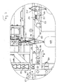
- FIG. 1 shows a transfer device 1 in side view. These are supplied to holding straps hanging packaging units of a safety gear 3 ago, which has taken over these packaging units of a closing device, which is shown in Figure 6 and will be explained.
- the catching device 3 conveys the packaging units, which are sausages in the example shown, but which can also be other items, along a second bar-shaped one Element 30, which is also referred to as a sword, and which is also visible in Figure 6 in side view and in Figure 4 in plan view.
- the transfer device 1 detects, and in particular grips, the packaging units in the end region of the sword in which it connects to the transfer device 1.
- the transfer device 1 is designed for the detachable mounting of a first rod-shaped element or rod 4, which is usually a smoke plug, when the packaging units are sausages.
- the transfer device transfers the hanging on the sword 30 packaging units to the rod 4. This is held in the transfer device 1 so that it can be arranged and held substantially coaxially with the sword 30 of the safety gear.
- FIG. 2 shows an end view of the transfer device 1 already described.
- the smoke plug or rod 4 which is detachably held in the transfer device in receiving means is again visible.
- a first end-side holding part 7 and a second end-side holding part can be provided ( Figure 1) wherein at least one of the holding parts, in Figure 1, the holding part 5, is driven, for example pneumatically driven, to effect releasable retention of the smoking plug.
- FIG. 2 shows a conveying means 52 which is driven by a chain 53 with a deflection 53 '(FIG. 3) by a drive (not shown in the drawing) which leads the individual bars 4 away from the transfer device and a multiplicity of loaded bars 4 for further processing of the held thereon Sausages ready.
- Another chain 53 is also provided on the other side of the device for the other end of the rods.
- the two chains are synchronized via a common drive shaft (not shown), which in the example shown is below the sausage hanging on the bar, but in the case of a chain guide of the chain 53 would lie vertically upwards instead of the chain guide shown above above the smoking bars.
- 51 is a magazine for the bars 4, from which an empty rod 4 or smoking can be brought back into the holding position in the transfer device 1.
- the transfer device is preferably equipped as a self-standing unit with a frame 6, by means of which it can be arranged at the end of the safety gear 3.
- the arranged on the transfer device rod changing device is designated 60 and has, for example for the two ends of the rod 4 and in both shots 5,7 for the rod depending on a carriage 61 which perform a translational back and forth movement in the direction of arrow D. can.
- a carriage 61 which perform a translational back and forth movement in the direction of arrow D. can.
- the carriage at the front end of the rod or in the region of the receptacle 5 is shown, which itself is not shown in the figure, so that the view of the free end of the rod 4 can be seen, the would be held in the recording 5.
- a fixed part 62 of the rod changing device contains the linear drive for the carriage, which can be formed individually for example by a pneumatic piston-cylinder arrangement for both carriages or for each carriage individually. Other drive variants are possible and familiar to those skilled in the execution of a reciprocating carriage movement.
- the drive of a first slide member 64 which is connected via a further slide member 67 with the Wegkitteil 66 of the carriage in conjunction.
- the part 64 forms a receptacle 65 for the next to be placed in loading position bar 4 'from.
- the Weggarteil 66 of the carriage extends to the rod 4, which is located in the receiving means 5, 7 of the transfer device and thus in loading position.
- the removal part 66 can also partially engage under the rod in order to support it while it is being guided away.
- the rod 4 is loaded by the transfer device with the packaging units, in particular sausages, which is illustrated in FIGS. 2 and 3 with the sausage 100 and will be explained in more detail below.
- the conveyor is gradually filled along its entire horizontal extent with loaded rods.
- Preferred is the explained procedure, in which the receiving pocket is stationary and waiting for the rod 4. Below is then each driven the chain 53 and brought the next pocket 54 in the waiting position. But it could also be done so that the respectively to be loaded with the rod pocket by the drive of the chain 53 is brought into loading position exactly when the rod is delivered by the carriage, which, however, a finer synchronization between the carriage and the drive of the chain 53 needed.
- the slide member 66 is lowered according to arrow E along the guides 68, so that the carriage under the bar now located in Beladepositon 4 'can go back to the starting position, in which the slide member again in the illustrated harnesse position is moved.
- the downward and upward movement of the slide member 66 along the guides 68 is e.g. also effected pneumatically or by means of electromagnets, which will not be explained further here, since it is readily apparent to the person skilled in the art how he can effect a corresponding movement.
- the carriage 61 is thus again in the position shown (initial position) and the rod 4 'is now in the loading position and is loaded.
- the recording 65 on the carriage for the next staff is still empty.
- the driven eg pneumatically or electromagnetically moves away, for example, pulled away , can be, so that the rod 4 'in the recording 65 falls.
- a retaining means 59 for the second lowermost rod 4" of the magazine is provided, for example in the form of in the rod 4 "both ends retractable bolt 59.
- the magazine 51 can preferably also be bent in the opposite direction, that is to say it has a curved configuration on the conveying means 52, which results in a more compact arrangement of the rod changing device and a Fillability of the magazine from the side of the conveyor 52 forth ago.
- the bar changing device is basically in the embodiment with slide in all types of transfer devices that hold the rod end, applicable.
- the detection means of the transfer device 1 for gripping the straps on the second rod-shaped element or the sword 30 are designed as hooks 10-23 which are attached to a revolving conveyor, which in the example shown is a chain 8, the at one end of the transfer device, which is the catcher 3 adjacent to a sprocket 9 is deflected.
- the chain also runs around a sprocket, which is driven by a controllable drive 25.
- the controller 50 shown only schematically, is correspondingly connected to the drive 25 by control lines. This drive is eg an electric motor drive with a servomotor.
- the gripping means 10-23 run with the chain 8 in the direction of arrow A and are deflected in the region of the end of the safety gear 3.
- the gripping of the holding loops of the packaging units takes place in such a way that the hook-shaped gripping means dip into a top-side groove 31 of the sword 30 after the diversion, via which groove the holding loop tensions.
- FIG. 4 shows a plan view of a part of the blade 30 with the groove 31 as well as holding straps 96 and 95 which span the groove 31.
- the straps can be promoted on the sword, this is kept flying by means of several pairs of retaining bolts, which are each withdrawn when passing a strap from the sword, in which time the holding of the sword is taken over by other pairs of retaining bolts.
- This is known in principle.
- FIG. 4 only the retaining bolt pairs 34, 35 and 36, 37 are shown as an example.
- the example shown with the continuously rotating conveyor with the gripping means arranged thereon is to be understood as a preferred example.
- FIG. 5 shows a detailed view of the gripping means, which are designed as hooks and their release by a triggering means for releasing the respective retaining loop.
- the chain 8 is again visible, on which the gripping means 18, 19 and 20 are fixedly arranged by fastening means 40.
- the single gripping means is designed in this preferred example as a hook, which has a pivotable hook part, which is movable from its gripping position for gripping the straps in a release position.
- the single hook has in this example a fixed hook portion 43 which is attached to the tab 40. Fixed is also the support member 44 for a spring means 45, in the example shown a compression spring.
- a pivotable hook portion 46 with the hook end 47 is pivotally mounted about an axis 41 on the fixed hook portion 43.
- a release part 42 is further arranged.
- This can be, for example, a fixed element or a rotatable roller.
- the gripping means 18 and 19 are shown in Figure 5 in the gripping position. In this position, they are previously immersed in the groove 32 of the sword 30 and have the respective retaining strap 93 and 92 of the sausage 103 and 102, respectively, on which the groove 30 spanning holding strap part used.
- the sausages 102 and 103 thus depend on the gripping means 18 and 19 while at the same time the smoke sticks 4 passes through the retaining loop.
- the sausages are conveyed in the direction of arrow B.
- the release of a packaging unit is now shown.
- the movable, pivotable hook member 46 is pivoted against the force of the compression spring 45, so that the hook tip 47 retracts behind the fixed hook part and the retaining loop is stripped from the hook tip 47.
- This stripping solution is a preferred example.
- the hook could also be pivoted so far that the strap slipped by the inclination of the hook tip itself by this and thus reaches the smoke sticks 4.
- the pivoting of the movable hook member 46 is effected by a trigger means.
- This release means is in the example shown, a trip block 28 having a control cam 28 'through which the respective release member 42 can be acted upon to cause the pivotal movement of the movable hook member 46 about the pivot axis 41.
- the trip block 28 is guided for example in a rail 29 and is driven by a conveyor 27 in the direction of arrow C.
- the triggering means thus runs counter to the conveying means of the gripping means and thus meets on its way from the end facing away from the sword of the smoking plug to the sword end of the smoking plug gradually to all funded by the gripping means packaging units.
- the gripping means release the packaging units.
- a motor 26 (FIG. 1) can be provided, which drives the toothed belt 27.
- the motor 26 is also connected to the controller 50, which can thus determine at which position a single packaging unit is set down or released.
- the triggering means may be carried out differently than shown in the preferred example.
- a plurality of fixedly positioned release means could be provided, which are individually controllable to act on a release part of the gripping means.
- Such individual triggering means could be actuated eg electromagnetically or pneumatically. In this way, the release and positioning can be effected, in which case the position can not be selected continuously by moving the trip block, but is given by the arrangement of the individual release means.
- the controller 50 is also preferably designed for the control of the rod changing device 60 and for the control of the means 58 and 59 in the magazine.
- FIG. 1 an arrangement of transfer device 1 with rod changing device 60, safety gear 3 and a closing machine 2 for the sausage-shaped packages is formed, as shown in Figures 1 and 6.
- the closing device 2 is a known closing device, which sets closure clips on the sausage-shaped packaging units.
- the retaining loop is attached to the respective packaging unit.
- the catching device 3 with the sword 30 takes over the individual straps and thus the packaging units and transports them along the sword 30 in the manner described or in another manner. Thereafter, the transfer device 1 described in detail adjoins.
- a controller 50 is provided, e.g.
- control of the closing machine 2 is synchronized, which controls all drives of the closing device, the safety gear and the transfer device including rod changing device synchronized, but at least the drives of the safety gear and the transfer device. There may also be individual controls on the devices that are synchronized with each other.
Landscapes
- Life Sciences & Earth Sciences (AREA)
- Engineering & Computer Science (AREA)
- Wood Science & Technology (AREA)
- Zoology (AREA)
- Food Science & Technology (AREA)
Applications Claiming Priority (1)
| Application Number | Priority Date | Filing Date | Title |
|---|---|---|---|
| CH13362006 | 2006-08-22 |
Publications (2)
| Publication Number | Publication Date |
|---|---|
| EP1891858A1 true EP1891858A1 (fr) | 2008-02-27 |
| EP1891858B1 EP1891858B1 (fr) | 2013-12-25 |
Family
ID=38779773
Family Applications (1)
| Application Number | Title | Priority Date | Filing Date |
|---|---|---|---|
| EP20070015071 Active EP1891858B1 (fr) | 2006-08-22 | 2007-08-01 | Dispositif de passage sur un dispositif de transmission pour unités d'emballage suspendues |
Country Status (2)
| Country | Link |
|---|---|
| EP (1) | EP1891858B1 (fr) |
| ES (1) | ES2451215T3 (fr) |
Cited By (9)
| Publication number | Priority date | Publication date | Assignee | Title |
|---|---|---|---|---|
| EP2305042A1 (fr) * | 2009-10-02 | 2011-04-06 | Poly-clip System GmbH & Co. KG | Système de stockage de produits |
| EP2305043A1 (fr) * | 2009-10-02 | 2011-04-06 | Poly-clip System GmbH & Co. KG | Procédé et système de pesée de produits |
| CH703003A1 (de) * | 2010-04-30 | 2011-10-31 | Tipper Tie Alpina Gmbh | Stabzufuhreinrichtung an einer Aufhängevorrichtung für wurstförmige Verpackung. |
| WO2011134095A1 (fr) | 2010-04-30 | 2011-11-03 | Tipper Tie Alpina Gmbh | Appareil à dispositif de fermeture et de suspension pour emballages en forme de saucisses |
| EP3072396A1 (fr) | 2015-03-23 | 2016-09-28 | Poly-clip System GmbH & Co. KG | Système et procédé de manutention pour produits en forme de saucisse |
| EP3103348A1 (fr) | 2015-06-09 | 2016-12-14 | Poly-clip System GmbH & Co. KG | Appareil et procédé de manipulation |
| CN107050658A (zh) * | 2017-04-17 | 2017-08-18 | 宁波中哲医疗科技有限公司 | 一种碳棒自动更换设备 |
| EP3732981A1 (fr) * | 2019-04-29 | 2020-11-04 | Poly-clip System GmbH & Co. KG | Procédé de chargement de saucisses |
| EP4275505B1 (fr) | 2022-05-11 | 2025-01-29 | Poly-clip System GmbH & Co. KG | Ligne de suspension avec mesure de longueur de tige de fumage |
Citations (4)
| Publication number | Priority date | Publication date | Assignee | Title |
|---|---|---|---|---|
| JPS63219334A (ja) * | 1987-03-09 | 1988-09-13 | ハイテツク株式会社 | ソ−セ−ジ懸吊装置のための竿部材供給装置 |
| DE3930876C1 (fr) * | 1989-09-15 | 1990-07-26 | Guenter 6080 Gross-Gerau De Kollross | |
| US20030096568A1 (en) * | 2001-11-16 | 2003-05-22 | Minoru Kasai | Method and apparatus for suspending a sausage from a stick |
| DE10340632B3 (de) * | 2003-09-03 | 2004-12-30 | Poly-Clip System Gmbh & Co. Kg | Antriebseinheit, Fördersystem und Repetiereinrichtung zum Bestücken einer Stange mit an Schlaufen hängenden Gegenständen |
-
2007
- 2007-08-01 EP EP20070015071 patent/EP1891858B1/fr active Active
- 2007-08-01 ES ES07015071T patent/ES2451215T3/es active Active
Patent Citations (4)
| Publication number | Priority date | Publication date | Assignee | Title |
|---|---|---|---|---|
| JPS63219334A (ja) * | 1987-03-09 | 1988-09-13 | ハイテツク株式会社 | ソ−セ−ジ懸吊装置のための竿部材供給装置 |
| DE3930876C1 (fr) * | 1989-09-15 | 1990-07-26 | Guenter 6080 Gross-Gerau De Kollross | |
| US20030096568A1 (en) * | 2001-11-16 | 2003-05-22 | Minoru Kasai | Method and apparatus for suspending a sausage from a stick |
| DE10340632B3 (de) * | 2003-09-03 | 2004-12-30 | Poly-Clip System Gmbh & Co. Kg | Antriebseinheit, Fördersystem und Repetiereinrichtung zum Bestücken einer Stange mit an Schlaufen hängenden Gegenständen |
Non-Patent Citations (1)
| Title |
|---|
| DATABASE WPI Week 198842, Derwent World Patents Index; AN 1988-297696 * |
Cited By (17)
| Publication number | Priority date | Publication date | Assignee | Title |
|---|---|---|---|---|
| EP2305042A1 (fr) * | 2009-10-02 | 2011-04-06 | Poly-clip System GmbH & Co. KG | Système de stockage de produits |
| EP2305043A1 (fr) * | 2009-10-02 | 2011-04-06 | Poly-clip System GmbH & Co. KG | Procédé et système de pesée de produits |
| US10051871B2 (en) | 2009-10-02 | 2018-08-21 | Poly-Clip System Gmbh & Co. Kg | System for transporting sausages |
| US8556687B2 (en) | 2009-10-02 | 2013-10-15 | Poly-Clip System Gmbh & Co. Kg | Method and system for weighing products |
| WO2011134096A1 (fr) | 2010-04-30 | 2011-11-03 | Tipper Tie Alpina Gmbh | Dispositif d'amenée de barres sur un système de suspension pour emballages en forme de saucissons |
| CN102883616A (zh) * | 2010-04-30 | 2013-01-16 | 体魄捆扎阿尔皮纳有限公司 | 用于香肠状包装件的悬挂装置上的杆供应装置 |
| US8545293B2 (en) | 2010-04-30 | 2013-10-01 | Tipper Tie Alpina Gmbh | Stick feeding unit in a suspension device for sausage-type packaging units |
| WO2011134095A1 (fr) | 2010-04-30 | 2011-11-03 | Tipper Tie Alpina Gmbh | Appareil à dispositif de fermeture et de suspension pour emballages en forme de saucisses |
| US8790166B2 (en) | 2010-04-30 | 2014-07-29 | Tipper Tie Alpina Gmbh | Combination of closing and suspension device for sausage-type packaging units |
| CH703003A1 (de) * | 2010-04-30 | 2011-10-31 | Tipper Tie Alpina Gmbh | Stabzufuhreinrichtung an einer Aufhängevorrichtung für wurstförmige Verpackung. |
| EP3072396A1 (fr) | 2015-03-23 | 2016-09-28 | Poly-clip System GmbH & Co. KG | Système et procédé de manutention pour produits en forme de saucisse |
| EP3103348A1 (fr) | 2015-06-09 | 2016-12-14 | Poly-clip System GmbH & Co. KG | Appareil et procédé de manipulation |
| CN107050658A (zh) * | 2017-04-17 | 2017-08-18 | 宁波中哲医疗科技有限公司 | 一种碳棒自动更换设备 |
| CN107050658B (zh) * | 2017-04-17 | 2023-07-25 | 宁波中哲医疗科技有限公司 | 一种碳棒自动更换设备 |
| EP3732981A1 (fr) * | 2019-04-29 | 2020-11-04 | Poly-clip System GmbH & Co. KG | Procédé de chargement de saucisses |
| US11116228B2 (en) | 2019-04-29 | 2021-09-14 | Poly-Clip System Gmbh & Co. Kg | Loading method |
| EP4275505B1 (fr) | 2022-05-11 | 2025-01-29 | Poly-clip System GmbH & Co. KG | Ligne de suspension avec mesure de longueur de tige de fumage |
Also Published As
| Publication number | Publication date |
|---|---|
| EP1891858B1 (fr) | 2013-12-25 |
| ES2451215T3 (es) | 2014-03-26 |
Similar Documents
| Publication | Publication Date | Title |
|---|---|---|
| EP1891859B1 (fr) | Dispositif de transmission pour unités d'emballage suspendues par des sangles | |
| EP1891858B1 (fr) | Dispositif de passage sur un dispositif de transmission pour unités d'emballage suspendues | |
| DE1610467C3 (de) | Verfahren und Vorrichtung zum Aufsetzen des Schiebers und der oberen Endglieder auf vorkonfektionierte gekuppelte Reißverschlüsse | |
| EP0129864B1 (fr) | Procédé et dispositif pour transférer des saucisses individuelles d'une machine à bourrer automatique aux barres d'enfumage ou de cuisson | |
| EP2537651B1 (fr) | Procédé et dispositif de coupe d'un tronçon d'aliments en tranches | |
| AT17337U1 (de) | Verfahren zum Befüllen der Taschen einer Transportvorrichtung in Form eines Hängeförderers sowie Vorrichtung zur Durchführung des Verfahrens | |
| DE10252876B4 (de) | Handlingsystem für Würste | |
| EP1985183B1 (fr) | Introduction de barre de fumoir et procédé d'introduction précis d'une barre de fumoir | |
| EP1844659A1 (fr) | Nouage direct d'un dispositif d'agrafe de saucisson et d'alimentation de saucisson | |
| EP2563152B1 (fr) | Dispositif d'alimentation d'un dispositif de suspension pour emballages en forme de saucisse | |
| EP1985185B1 (fr) | Dispositif de cartouche de tiges sur un dispositif de transmission pour unités d'emballage suspendues | |
| CH454010A (de) | Vorrichtung zum Einlegen von auf einer Zuführeinrichtung ausgerichteten Süsswarenstücken in Verpackungen | |
| EP2008522A1 (fr) | Procédé et dispositif destinés à la saisie de portions à boucles | |
| EP2563151B1 (fr) | Appareil a dispositif de fermeture et de suspension pour emballages en forme de saucisses | |
| DE19900651A1 (de) | Vorrichtung zum Vereinzeln von Würsten | |
| CH687714A5 (de) | Vorrichtung zur Handhabung von Litzen fuer Kettfadeneinziehmaschinen. | |
| DE2727924C2 (de) | Vorrichtung zur Übergabe einer vorbestimmten Anzahl zylindrischer Gegenstände, insbesondere von Zigarettenhülsen mit Filterspitze, an eine Verpackung | |
| DE2016054C3 (de) | Vorrichtung zum Überführen von Behältern in den Förderer einer Einkocheinrichtung | |
| DE3300012C1 (de) | Programmgesteuerte Aufhängevorrichtung für portionierte Wurstketten | |
| DE2200311C2 (de) | Vorrichtung zum Transportieren und Ablegen | |
| DE2001932C3 (de) | Vorrichtung zum Transportieren von Stranggut | |
| AT394324B (de) | Verfahren und anlage zum entzundern von rundstahlstaeben | |
| EP2380831B1 (fr) | Dispositif destiné au transport et à l'isolation de barres de fumoir | |
| DE10046417C1 (de) | Einlegevorrichtung für an Fadenschlaufen an Spießen hängende Waren | |
| EP2277383B1 (fr) | Dispositif et procédé de suspension de saucissons |
Legal Events
| Date | Code | Title | Description |
|---|---|---|---|
| PUAI | Public reference made under article 153(3) epc to a published international application that has entered the european phase |
Free format text: ORIGINAL CODE: 0009012 |
|
| AK | Designated contracting states |
Kind code of ref document: A1 Designated state(s): AT BE BG CH CY CZ DE DK EE ES FI FR GB GR HU IE IS IT LI LT LU LV MC MT NL PL PT RO SE SI SK TR |
|
| AX | Request for extension of the european patent |
Extension state: AL BA HR MK YU |
|
| 17P | Request for examination filed |
Effective date: 20080826 |
|
| 17Q | First examination report despatched |
Effective date: 20080929 |
|
| AKX | Designation fees paid |
Designated state(s): DE FR IT |
|
| RBV | Designated contracting states (corrected) |
Designated state(s): AT BE BG CH CY CZ DE DK EE ES FI FR GB GR HU IE IS IT LI LT LU LV MC MT NL PL PT RO SE SI SK TR |
|
| GRAP | Despatch of communication of intention to grant a patent |
Free format text: ORIGINAL CODE: EPIDOSNIGR1 |
|
| GRAS | Grant fee paid |
Free format text: ORIGINAL CODE: EPIDOSNIGR3 |
|
| RAP1 | Party data changed (applicant data changed or rights of an application transferred) |
Owner name: TIPPER TIE ALPINA GMBH |
|
| GRAA | (expected) grant |
Free format text: ORIGINAL CODE: 0009210 |
|
| AK | Designated contracting states |
Kind code of ref document: B1 Designated state(s): AT BE BG CH CY CZ DE DK EE ES FI FR GB GR HU IE IS IT LI LT LU LV MC MT NL PL PT RO SE SI SK TR |
|
| REG | Reference to a national code |
Ref country code: GB Ref legal event code: FG4D Free format text: NOT ENGLISH |
|
| REG | Reference to a national code |
Ref country code: CH Ref legal event code: EP |
|
| REG | Reference to a national code |
Ref country code: AT Ref legal event code: REF Ref document number: 646090 Country of ref document: AT Kind code of ref document: T Effective date: 20140115 |
|
| REG | Reference to a national code |
Ref country code: IE Ref legal event code: FG4D Free format text: LANGUAGE OF EP DOCUMENT: GERMAN |
|
| REG | Reference to a national code |
Ref country code: DE Ref legal event code: R096 Ref document number: 502007012621 Country of ref document: DE Effective date: 20140213 |
|
| REG | Reference to a national code |
Ref country code: ES Ref legal event code: FG2A Ref document number: 2451215 Country of ref document: ES Kind code of ref document: T3 Effective date: 20140326 |
|
| PG25 | Lapsed in a contracting state [announced via postgrant information from national office to epo] |
Ref country code: LT Free format text: LAPSE BECAUSE OF FAILURE TO SUBMIT A TRANSLATION OF THE DESCRIPTION OR TO PAY THE FEE WITHIN THE PRESCRIBED TIME-LIMIT Effective date: 20131225 Ref country code: SE Free format text: LAPSE BECAUSE OF FAILURE TO SUBMIT A TRANSLATION OF THE DESCRIPTION OR TO PAY THE FEE WITHIN THE PRESCRIBED TIME-LIMIT Effective date: 20131225 Ref country code: FI Free format text: LAPSE BECAUSE OF FAILURE TO SUBMIT A TRANSLATION OF THE DESCRIPTION OR TO PAY THE FEE WITHIN THE PRESCRIBED TIME-LIMIT Effective date: 20131225 |
|
| REG | Reference to a national code |
Ref country code: NL Ref legal event code: VDEP Effective date: 20131225 |
|
| REG | Reference to a national code |
Ref country code: LT Ref legal event code: MG4D |
|
| PG25 | Lapsed in a contracting state [announced via postgrant information from national office to epo] |
Ref country code: LV Free format text: LAPSE BECAUSE OF FAILURE TO SUBMIT A TRANSLATION OF THE DESCRIPTION OR TO PAY THE FEE WITHIN THE PRESCRIBED TIME-LIMIT Effective date: 20131225 |
|
| PG25 | Lapsed in a contracting state [announced via postgrant information from national office to epo] |
Ref country code: EE Free format text: LAPSE BECAUSE OF FAILURE TO SUBMIT A TRANSLATION OF THE DESCRIPTION OR TO PAY THE FEE WITHIN THE PRESCRIBED TIME-LIMIT Effective date: 20131225 Ref country code: IS Free format text: LAPSE BECAUSE OF FAILURE TO SUBMIT A TRANSLATION OF THE DESCRIPTION OR TO PAY THE FEE WITHIN THE PRESCRIBED TIME-LIMIT Effective date: 20140425 |
|
| PG25 | Lapsed in a contracting state [announced via postgrant information from national office to epo] |
Ref country code: CY Free format text: LAPSE BECAUSE OF FAILURE TO SUBMIT A TRANSLATION OF THE DESCRIPTION OR TO PAY THE FEE WITHIN THE PRESCRIBED TIME-LIMIT Effective date: 20131225 Ref country code: CZ Free format text: LAPSE BECAUSE OF FAILURE TO SUBMIT A TRANSLATION OF THE DESCRIPTION OR TO PAY THE FEE WITHIN THE PRESCRIBED TIME-LIMIT Effective date: 20131225 Ref country code: PL Free format text: LAPSE BECAUSE OF FAILURE TO SUBMIT A TRANSLATION OF THE DESCRIPTION OR TO PAY THE FEE WITHIN THE PRESCRIBED TIME-LIMIT Effective date: 20131225 Ref country code: PT Free format text: LAPSE BECAUSE OF FAILURE TO SUBMIT A TRANSLATION OF THE DESCRIPTION OR TO PAY THE FEE WITHIN THE PRESCRIBED TIME-LIMIT Effective date: 20140428 Ref country code: SK Free format text: LAPSE BECAUSE OF FAILURE TO SUBMIT A TRANSLATION OF THE DESCRIPTION OR TO PAY THE FEE WITHIN THE PRESCRIBED TIME-LIMIT Effective date: 20131225 Ref country code: NL Free format text: LAPSE BECAUSE OF FAILURE TO SUBMIT A TRANSLATION OF THE DESCRIPTION OR TO PAY THE FEE WITHIN THE PRESCRIBED TIME-LIMIT Effective date: 20131225 Ref country code: RO Free format text: LAPSE BECAUSE OF FAILURE TO SUBMIT A TRANSLATION OF THE DESCRIPTION OR TO PAY THE FEE WITHIN THE PRESCRIBED TIME-LIMIT Effective date: 20131225 |
|
| REG | Reference to a national code |
Ref country code: DE Ref legal event code: R026 Ref document number: 502007012621 Country of ref document: DE |
|
| PLBI | Opposition filed |
Free format text: ORIGINAL CODE: 0009260 |
|
| PG25 | Lapsed in a contracting state [announced via postgrant information from national office to epo] |
Ref country code: DK Free format text: LAPSE BECAUSE OF FAILURE TO SUBMIT A TRANSLATION OF THE DESCRIPTION OR TO PAY THE FEE WITHIN THE PRESCRIBED TIME-LIMIT Effective date: 20131225 |
|
| PLAX | Notice of opposition and request to file observation + time limit sent |
Free format text: ORIGINAL CODE: EPIDOSNOBS2 |
|
| 26 | Opposition filed |
Opponent name: POLY-CLIP SYSTEM GMBH & CO. KG Effective date: 20140925 |
|
| REG | Reference to a national code |
Ref country code: DE Ref legal event code: R026 Ref document number: 502007012621 Country of ref document: DE Effective date: 20140925 |
|
| PLAF | Information modified related to communication of a notice of opposition and request to file observations + time limit |
Free format text: ORIGINAL CODE: EPIDOSCOBS2 |
|
| PG25 | Lapsed in a contracting state [announced via postgrant information from national office to epo] |
Ref country code: LU Free format text: LAPSE BECAUSE OF FAILURE TO SUBMIT A TRANSLATION OF THE DESCRIPTION OR TO PAY THE FEE WITHIN THE PRESCRIBED TIME-LIMIT Effective date: 20140801 Ref country code: MC Free format text: LAPSE BECAUSE OF FAILURE TO SUBMIT A TRANSLATION OF THE DESCRIPTION OR TO PAY THE FEE WITHIN THE PRESCRIBED TIME-LIMIT Effective date: 20131225 |
|
| REG | Reference to a national code |
Ref country code: CH Ref legal event code: PL |
|
| GBPC | Gb: european patent ceased through non-payment of renewal fee |
Effective date: 20140801 |
|
| PG25 | Lapsed in a contracting state [announced via postgrant information from national office to epo] |
Ref country code: BE Free format text: LAPSE BECAUSE OF NON-PAYMENT OF DUE FEES Effective date: 20140831 Ref country code: LI Free format text: LAPSE BECAUSE OF NON-PAYMENT OF DUE FEES Effective date: 20140831 Ref country code: CH Free format text: LAPSE BECAUSE OF NON-PAYMENT OF DUE FEES Effective date: 20140831 |
|
| PLBB | Reply of patent proprietor to notice(s) of opposition received |
Free format text: ORIGINAL CODE: EPIDOSNOBS3 |
|
| REG | Reference to a national code |
Ref country code: IE Ref legal event code: MM4A |
|
| PG25 | Lapsed in a contracting state [announced via postgrant information from national office to epo] |
Ref country code: SI Free format text: LAPSE BECAUSE OF FAILURE TO SUBMIT A TRANSLATION OF THE DESCRIPTION OR TO PAY THE FEE WITHIN THE PRESCRIBED TIME-LIMIT Effective date: 20131225 |
|
| REG | Reference to a national code |
Ref country code: FR Ref legal event code: ST Effective date: 20150430 |
|
| PG25 | Lapsed in a contracting state [announced via postgrant information from national office to epo] |
Ref country code: GB Free format text: LAPSE BECAUSE OF NON-PAYMENT OF DUE FEES Effective date: 20140801 |
|
| PG25 | Lapsed in a contracting state [announced via postgrant information from national office to epo] |
Ref country code: IE Free format text: LAPSE BECAUSE OF NON-PAYMENT OF DUE FEES Effective date: 20140801 Ref country code: FR Free format text: LAPSE BECAUSE OF NON-PAYMENT OF DUE FEES Effective date: 20140901 |
|
| REG | Reference to a national code |
Ref country code: AT Ref legal event code: MM01 Ref document number: 646090 Country of ref document: AT Kind code of ref document: T Effective date: 20140801 |
|
| PG25 | Lapsed in a contracting state [announced via postgrant information from national office to epo] |
Ref country code: AT Free format text: LAPSE BECAUSE OF NON-PAYMENT OF DUE FEES Effective date: 20140801 |
|
| PG25 | Lapsed in a contracting state [announced via postgrant information from national office to epo] |
Ref country code: BG Free format text: LAPSE BECAUSE OF FAILURE TO SUBMIT A TRANSLATION OF THE DESCRIPTION OR TO PAY THE FEE WITHIN THE PRESCRIBED TIME-LIMIT Effective date: 20131225 |
|
| PG25 | Lapsed in a contracting state [announced via postgrant information from national office to epo] |
Ref country code: GR Free format text: LAPSE BECAUSE OF FAILURE TO SUBMIT A TRANSLATION OF THE DESCRIPTION OR TO PAY THE FEE WITHIN THE PRESCRIBED TIME-LIMIT Effective date: 20140326 Ref country code: MT Free format text: LAPSE BECAUSE OF FAILURE TO SUBMIT A TRANSLATION OF THE DESCRIPTION OR TO PAY THE FEE WITHIN THE PRESCRIBED TIME-LIMIT Effective date: 20131225 |
|
| PG25 | Lapsed in a contracting state [announced via postgrant information from national office to epo] |
Ref country code: TR Free format text: LAPSE BECAUSE OF FAILURE TO SUBMIT A TRANSLATION OF THE DESCRIPTION OR TO PAY THE FEE WITHIN THE PRESCRIBED TIME-LIMIT Effective date: 20131225 Ref country code: ES Free format text: LAPSE BECAUSE OF NON-PAYMENT OF DUE FEES Effective date: 20070802 Ref country code: HU Free format text: LAPSE BECAUSE OF FAILURE TO SUBMIT A TRANSLATION OF THE DESCRIPTION OR TO PAY THE FEE WITHIN THE PRESCRIBED TIME-LIMIT; INVALID AB INITIO Effective date: 20070801 |
|
| PLCK | Communication despatched that opposition was rejected |
Free format text: ORIGINAL CODE: EPIDOSNREJ1 |
|
| PG25 | Lapsed in a contracting state [announced via postgrant information from national office to epo] |
Ref country code: ES Free format text: LAPSE BECAUSE OF NON-PAYMENT OF DUE FEES Effective date: 20140802 |
|
| APAH | Appeal reference modified |
Free format text: ORIGINAL CODE: EPIDOSCREFNO |
|
| APBM | Appeal reference recorded |
Free format text: ORIGINAL CODE: EPIDOSNREFNO |
|
| APBP | Date of receipt of notice of appeal recorded |
Free format text: ORIGINAL CODE: EPIDOSNNOA2O |
|
| REG | Reference to a national code |
Ref country code: DE Ref legal event code: R100 Ref document number: 502007012621 Country of ref document: DE |
|
| APBU | Appeal procedure closed |
Free format text: ORIGINAL CODE: EPIDOSNNOA9O |
|
| PLBN | Opposition rejected |
Free format text: ORIGINAL CODE: 0009273 |
|
| STAA | Information on the status of an ep patent application or granted ep patent |
Free format text: STATUS: OPPOSITION REJECTED |
|
| 27O | Opposition rejected |
Effective date: 20170224 |
|
| PGFP | Annual fee paid to national office [announced via postgrant information from national office to epo] |
Ref country code: DK Payment date: 20170519 Year of fee payment: 6 |
|
| REG | Reference to a national code |
Ref country code: DE Ref legal event code: R082 Ref document number: 502007012621 Country of ref document: DE Representative=s name: GLAWE DELFS MOLL PARTNERSCHAFT MBB VON PATENT-, DE Ref country code: DE Ref legal event code: R081 Ref document number: 502007012621 Country of ref document: DE Owner name: TIPPER TIE TECHNOPACK GMBH, DE Free format text: FORMER OWNER: TIPPER TIE ALPINA GMBH, FLAWIL, CH |
|
| PG25 | Lapsed in a contracting state [announced via postgrant information from national office to epo] |
Ref country code: IT Free format text: LAPSE BECAUSE OF NON-PAYMENT OF DUE FEES Effective date: 20180801 |
|
| P01 | Opt-out of the competence of the unified patent court (upc) registered |
Effective date: 20230525 |
|
| PGFP | Annual fee paid to national office [announced via postgrant information from national office to epo] |
Ref country code: DE Payment date: 20250604 Year of fee payment: 19 |