EP1893053B1 - Modular furniture assembly - Google Patents
Modular furniture assembly Download PDFInfo
- Publication number
- EP1893053B1 EP1893053B1 EP06770061.7A EP06770061A EP1893053B1 EP 1893053 B1 EP1893053 B1 EP 1893053B1 EP 06770061 A EP06770061 A EP 06770061A EP 1893053 B1 EP1893053 B1 EP 1893053B1
- Authority
- EP
- European Patent Office
- Prior art keywords
- base
- transverse member
- coupler
- assembly
- transverse
- Prior art date
- Legal status (The legal status is an assumption and is not a legal conclusion. Google has not performed a legal analysis and makes no representation as to the accuracy of the status listed.)
- Expired - Lifetime
Links
Images




Classifications
-
- A—HUMAN NECESSITIES
- A47—FURNITURE; DOMESTIC ARTICLES OR APPLIANCES; COFFEE MILLS; SPICE MILLS; SUCTION CLEANERS IN GENERAL
- A47C—CHAIRS; SOFAS; BEDS
- A47C7/00—Parts, details, or accessories of chairs or stools
- A47C7/02—Seat parts
-
- A—HUMAN NECESSITIES
- A47—FURNITURE; DOMESTIC ARTICLES OR APPLIANCES; COFFEE MILLS; SPICE MILLS; SUCTION CLEANERS IN GENERAL
- A47C—CHAIRS; SOFAS; BEDS
- A47C13/00—Convertible chairs, stools or benches
- A47C13/005—Modular seating
-
- A—HUMAN NECESSITIES
- A47—FURNITURE; DOMESTIC ARTICLES OR APPLIANCES; COFFEE MILLS; SPICE MILLS; SUCTION CLEANERS IN GENERAL
- A47C—CHAIRS; SOFAS; BEDS
- A47C17/00—Sofas; Couches; Beds
- A47C17/04—Seating furniture, e.g. sofas, couches, settees, or the like, with movable parts changeable to beds; Chair beds
- A47C17/045—Seating furniture having loose or by fabric hinge connected cushions changeable to beds
-
- A—HUMAN NECESSITIES
- A47—FURNITURE; DOMESTIC ARTICLES OR APPLIANCES; COFFEE MILLS; SPICE MILLS; SUCTION CLEANERS IN GENERAL
- A47C—CHAIRS; SOFAS; BEDS
- A47C4/00—Foldable, collapsible or dismountable chairs
- A47C4/02—Dismountable chairs
- A47C4/028—Upholstered chairs, e.g. metal, plastic or wooden chairs
-
- A—HUMAN NECESSITIES
- A47—FURNITURE; DOMESTIC ARTICLES OR APPLIANCES; COFFEE MILLS; SPICE MILLS; SUCTION CLEANERS IN GENERAL
- A47C—CHAIRS; SOFAS; BEDS
- A47C7/00—Parts, details, or accessories of chairs or stools
-
- Y—GENERAL TAGGING OF NEW TECHNOLOGICAL DEVELOPMENTS; GENERAL TAGGING OF CROSS-SECTIONAL TECHNOLOGIES SPANNING OVER SEVERAL SECTIONS OF THE IPC; TECHNICAL SUBJECTS COVERED BY FORMER USPC CROSS-REFERENCE ART COLLECTIONS [XRACs] AND DIGESTS
- Y10—TECHNICAL SUBJECTS COVERED BY FORMER USPC
- Y10T—TECHNICAL SUBJECTS COVERED BY FORMER US CLASSIFICATION
- Y10T403/00—Joints and connections
- Y10T403/71—Rod side to plate or side
- Y10T403/7164—One rod held between bight and other rod extending through aperture in leg of connector
-
- Y—GENERAL TAGGING OF NEW TECHNOLOGICAL DEVELOPMENTS; GENERAL TAGGING OF CROSS-SECTIONAL TECHNOLOGIES SPANNING OVER SEVERAL SECTIONS OF THE IPC; TECHNICAL SUBJECTS COVERED BY FORMER USPC CROSS-REFERENCE ART COLLECTIONS [XRACs] AND DIGESTS
- Y10—TECHNICAL SUBJECTS COVERED BY FORMER USPC
- Y10T—TECHNICAL SUBJECTS COVERED BY FORMER US CLASSIFICATION
- Y10T403/00—Joints and connections
- Y10T403/71—Rod side to plate or side
- Y10T403/7176—Resilient clip
Definitions
- the invention relates to the field of furniture. Particularly, the invention relates to a modular furniture assembly.
- a futon bed serves the function of both a bed and a couch.
- futon beds are bulky, and thus subject to the cost factors described above.
- futon mattresses are often thin and uncomfortable both as a couch and as a bed.
- the invention relates to a modular furniture assembly that can be assembled, disassembled, rearranged, moved and cleaned in a quick and efficient manner with minimal effort.
- a modular furniture assembly comprising:
- the base comprises at least one substantially flat portion that abuts a substantially flat portion of the transverse member.
- the modular furniture assembly further comprises:
- a frame of the base and a frame of the transverse member each have a corresponding aperture therein that receives a portion of a coupler therein.
- the modular furniture assembly further comprises:
- the modular furniture assembly further comprises:
- the base comprises:
- the length (x') of the transverse member is a length in a horizontal plane; the length (x) of the base is a length in said horizontal plane; the width (y) of the base is a width in said horizontal plane; and the width (z) of the transverse member is a width in said horizontal plane.
- the height (h') of the transverse member is substantially greater than the height (h) of the base.
- the height (h') of the transverse member is perpendicular to length (x') of the transverse member.
- the modular furniture assembly further comprises:
- the base has a frame having an aperture in a top portion thereof and wherein the transverse member has a frame having an aperture in a side portion thereof and wherein a coupler is receivable downwardly into the aperture in the top portion of the base frame and into the aperture in the side portion of the transverse member frame to thereby sandwich a portion of the base and a portion of the transverse member between portions of the coupler.
- the modular furniture assembly further comprises:
- the modular furniture assembly further comprises:
- the modular furniture assembly further comprises:
- the base may serve as a support surface on which a user can sit, and the transverse member may act as a resting surface for a user's back or arm.
- the coupler is configured to allow a user to quickly couple or decouple the transverse member and the base with minimal effort without the use of a tool.
- the ease of coupling a transverse member to the base enables a consumer to easily form many configurations of furniture assemblies.
- the base is configured such that it can be positioned adjacent the transverse member in a variety of ways and detachably coupled thereto so as to provide a variety of configurations of modular furniture assemblies.
- many bases and transverse members can be utilized to form a variety of different furniture assemblies.
- one embodiment utilizes one base and one transverse member coupled together to form a chair.
- three transverse members are coupled to one base to form an arm chair.
- the base(s) and transverse member(s) can be placed in a variety of different positions so as to form a variety of different chairs.
- one or more bases having a substantially similar configuration can be employed with one or more transverse members having a substantially similar configuration.
- the standardized configuration of bases and transverse members enables a user to form a variety of different types and configurations of furniture assemblies. This also makes manufacturing convenient because a manufacturer can produce a series of bases that have a substantially similar configuration and a series of transverse members that have a substantially similar configuration, then arrange (or allow the end user to arrange) the bases and transverse members into a variety of configurations to form different types of furniture.
- the user can purchase one or more bases having the same configuration and one or more transverse members having the same configuration, then combine them to form a number of different furniture assemblies.
- a first base and a first transverse member can be employed to form a chair having a back rest.
- Second and third transverse members having a substantially similar configuration as the first transverse member can be added to form an armchair.
- a couch can be formed by adding: (i) a second base having a substantially similar configuration as the first base; and (ii) second, third and fourth transverse members having a substantially similar configuration as the first transverse member.
- An endless variety of furniture assemblies can be formed by utilizing bases and transverse members having standardized, substantially similar configurations, respectively.
- the spatial relationship further enables the manufacturer to proportionately size the bases and transverse members to form furniture assemblies for different sizes of individuals.
- the bases and transverse members can be proportionately sized to form furniture assemblies for children.
- the bases and transverse members can be proportionately sized to form furniture assemblies for adults, or even oversized adults.
- the bases(s) and transverse members(s) of the present invention can be utilized to form a variety of sizes of furniture.
- the configuration of the base and transverse member of the present invention provides many benefits to both the consumer and retailer.
- the present invention enables the consumer to have a piece of furniture in a remote location where previously other pieces of furniture could not be moved due to their bulkiness and/or size.
- the present invention is easily disassembled, thus enabling a consumer to locate the base(s) and/or transverse member(s) in an otherwise inaccessible location and then assemble them to form a furniture assembly.
- the present invention enables a manufacturer and/or retailer to stock two pieces of furniture, i.e. a base and a transverse member. This is advantageous for shipping and storing.
- the manufacturer and/or retailer is only required to store two primary pieces and is able to stack the bases or transverse members having the same respective configuration on top of each other when loading and unloading from freight.
- the bases and transverse members can be stacked in an orderly fashion in storage.
- the transverse member and the base may include removable outer liners.
- the removable outer liners allow a consumer to easily launder the furniture assembly. Further, utilizing a removable outer liner allows a consumer to interchange liners of different shades and styles to create a unique and customized furniture assembly.
- the furniture assembly of the present invention is versatile, modular, interchangeable and convenient.
- the invention relates to a modular furniture assembly that can be assembled, disassembled, rearranged, moved and cleaned in a quick and efficient manner with minimal effort.
- the invention further relates to a modular furniture assembly that has a spatial relationship that enables a user to form a number of different furniture assemblies.
- the modular furniture assembly comprises a base, at least one transverse member and a coupler configured to detachably couple the transverse member to the base so as to form a chair.
- the configuration of the base and transverse member enable a user to form a number of different furniture assemblies.
- the base serves as a support surface on which a user can sit, and the transverse member acts as a resting surface for a user's back or arm.
- the base is configured such that transverse member can be positioned adjacent the base in a variety of positions and detachably coupled thereto to form different types of furniture assemblies.
- the coupler is configured to allow a user to quickly couple or decouple the transverse member and the base with minimal effort without the use of a tool.
- the ease of coupling a transverse member to the base provides for the capability of easily forming many configurations of furniture assemblies. Many bases and transverse members can be utilized to form a variety of differing furniture assemblies.
- the base and transverse member can be proportionately sized to accommodate different sizes of individuals. As such, a variety of types, sizes and configurations of furniture can be made in a quick and convenient fashion by utilizing the present invention.
- FIG 1 illustrates an exemplary embodiment of a modular furniture assembly 10.
- modular furniture assembly 10 comprises a base 12 and a transverse member 14 detachably coupled to base 12 by a coupler 15 ( Figure 4 ).
- Base 12 and transverse member 14 are adapted to be detachably coupled to each other in a variety of ways and configurations so as to form a variety of unique and custom furniture assemblies. Further, base 12 and transverse member 14 are sized and configured according to a defined spatial relationship.
- base 12 and transverse member 14 enable: (i) the convenient formation of a variety of different types of furniture assemblies; (ii) the convenient formation of a variety of different configurations of furniture assemblies; and (iii) a manufacturer to proportionately size the bases and transverse members for different sizes of individuals, such as for children or for adults.
- Base 12 is configured to provide a comfortable sitting surface for a consumer.
- Base 12 is also configured to be easily disassembled for rearranging, moving, storing and/or shipping.
- base 12 comprises a frame assembly 16, a cushion 18 and a plurality of feet 20a-d mounted on frame assembly 16.
- Frame assembly 16 is configured to support the weight of a consumer while the consumer is sitting on base 12.
- Cushion 18 is configured to be mounted on frame assembly 16 so as to provide a useful and comfortable sitting area for a consumer. Cushion 18 can be easily mounted on or removed from frame assembly 16.
- Feet 20a-d are coupled to the underside of frame assembly 16.
- Feet 20a-d can be coupled to frame assembly 16 in a variety of ways.
- feet 20a-d are coupled by screws.
- feet 20a-d can be easily coupled to and/or removed from frame assembly 16 so as to facilitate ease in packaging, shipping, storing, moving and/or replacing feet 20a-d.
- feet 20a-d can be coupled to frame assembly 16 in a more permanent fashion, such as with a nail, an epoxy or glue, or any combination thereof.
- Feet 20a-d facilitate the coupling of transverse member 14 to base 12 when used in connection with a foot coupler, such as foot coupler 34 and/or 34a.
- Feet 20a-d are further configured to support the weight of a consumer and to elevate base 12 above the floor.
- feet 20a-d are coupled to frame assembly 16 by screws, the removability of feet 20a-d in conjunction with the removability of cushion 18 enables base 12 to be easily disassembled for rearranging, moving, storing and/or shipping.
- Base 12 includes a plurality of abutting surfaces 26a-d that are configured to be positionable adjacent to and abut with an abutting surface 28 of transverse member 14. As will be discussed more fully herein, base 12 is configured such that transverse member 14 can be positioned adjacent any abutting surface 26a-d to form a variety of different furniture assemblies.
- base 12 and transverse member 14 have a defined spatial relationship.
- the spatial relationship between base 12 and transverse member 14 enable the formation of a variety of different types, sizes and configurations of furniture assemblies.
- base has a length (x) and a width (y), wherein the length (x) of base 12 is greater than the width (y) of base 12, and transverse member 14 has a length (x') and a width (z), wherein the length (x') of transverse member 14 is greater than the width (z) of transverse member 14.
- base 12 and transverse member 14 are configured such that the length (x) of base 12 is substantially equal to the length (x') of transverse member 14 and the length (x) of base 12 is substantially equal to the sum of the width (y) of base 12 and the width (z) of transverse member 14.
- (x) is substantially equal to (y) + (z).
- This relationship of the length (x) of base 12 being substantially equal to the sum of the width (y) of base 12 and width (z) of transverse member 14 is the defined spatial relationship between base 12 and transverse member 14.
- the height (h') of transverse member 14 is substantially greater than the height (h) of base 12, such that transverse member 14 can be conveniently employed as a backrest or armrest while base 12 is employed as a seat.
- first base 12 and a first transverse member 14 are utilized to form a chair.
- Second and third transverse members 14 having a substantially similar configuration as the first transverse member 14 can be added to form an arm chair having a first arm rest and a second arm rest, as illustrated in Figure 6c .
- the phrase substantially similar configuration can mean that the bases and/or transverse members are respectively sized and configured so as to be interchangeable.
- a couch can be formed by adding: (i) a second base 12 having a substantially similar configuration as the first base 12; and (ii) a second, third and fourth transverse member 14 having a substantially similar configuration as the first transverse member 14, as illustrated in Figure 6e and Figure 6f .
- This ability to add base(s) and/or transverse member(s) to form different types of furniture is how the defined spatial relationship enables a user to conveniently form a variety of different types of furniture.
- the defined spatial relationship enables a user to conveniently form a variety of different configurations of furniture assemblies.
- the couches formed by utilizing two bases 12 and four transverse members 14 can be arranged so as to form a love seat, as illustrated by Figure 6e , or a deep sofa, as illustrated by Figure 6f .
- the love seat of Figure 6e and the deep sofa of Figure 6f employ the same bases 12 and the same transverse members 14, but are arranged differently.
- the defined spatial relationship of the present invention enables a user to conveniently form a variety of different configurations of furniture assemblies.
- the defined spatial relationship also enables a manufacturer to manufacture different sizes of bases and transverse members so as to accommodate different sizes of individuals.
- a manufacturer can manufacture a base and a transverse member such that when the base and transverse member are detachably coupled together a furniture assembly is formed that is sized for a child, but may be too small for an adult to use comfortably.
- a manufacturer utilizing the spatial relationship, can enlarge the size of the base(s) and transverse member(s) such that when the base(s) and transverse member(s) are coupled together a furniture assembly is formed that is sized to accommodate an adult comfortably.
- the spatial relationship between base 12 and transverse member 14 enables the formation of a variety of different sizes of furniture assemblies.
- transverse member 14 is configured to provide lateral support to a consumer when base 12 is coupled thereto.
- Transverse member 14 can be positioned adjacent any abutting surface 26a-d of base 12 to form a variety of furniture assemblies.
- a plurality of feet 30a-b are coupled to the underside of traverse member 14.
- Feet 30a-b are configured to facilitate the coupling of transverse member 14 to base 12.
- Feet 30a-b are further configured to support the weight of a consumer and to elevate transverse member 14 above a floor on which transverse member 14 is positioned.
- Feet 30a-b can be coupled to transverse member 14 in a similar fashion as feet 20a-d are coupled to base 12.
- feet 30a-b are each positioned such that each are offset from the front and back surfaces and respective adjacent side surfaces of transverse member 14 an equal distance, the "offset distance.” For example, if the width (z) of transverse member is ten inches, the offset distance is five inches. Thus, feet 30a-b are each positioned five inches from the front surface and five inches from the back surface of transverse member 14 (i.e., in the middle of the front and back surfaces), and are each positioned five inches from respective adjacent side surfaces of transverse member 14. Similarly, feet 20a-d of base 12 are each positioned such that each are offset from respective adjacent abutting surfaces 26a-d the offset distance.
- foot 20a is offset from both abutting surface 26a and abutting surface 26b the offset distance;
- foot 20b is offset from both abutting surface 26b and abutting surface 26c the offset distance;
- foot 20c is offset from both abutting surface 26c and abutting surface 26d the offset distance;
- foot 20d is offset from both abutting surface 26d and abutting surface 26a the offset distance.
- modular furniture assembly 10 further includes multiple foot couplers 34-35, which may be identical, for example.
- Foot couplers 34-35 are adapted to facilitate the coupling of transverse member 14 to base 12.
- Foot couplers 34-35 are further adapted to provide support to base 12 and transverse member 14 when coupled thereto.
- Foot coupler 34 utilizes foot 20d of base 12 and foot 30a of transverse member 14 which is adjacent to foot 20d of base to facilitate coupling of transverse member 14 to base 12.
- foot coupler 35 utilizes foot 20c of base 12 and adjacent foot 30b of transverse member 14 to facilitate coupling of transverse member 14 to base 12.
- traverse member 14, frame assembly 16 and cushion 18 each include a selectively removable outer liner 32, 22, 24, respectively.
- Removable outer liners 32, 22, 24 are configured to be easily removed and reattached so as to provide easy laundering thereof, as discussed more fully herein. Further, the selective removability of outer liners 32, 22, 24 allows a consumer to mix and match colors and designs to create a unique and custom furniture assembly.
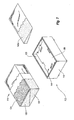
- FIG. 2 illustrates an exploded cutaway view of base 12.
- frame assembly 16 comprises a frame 36 and a cushion assembly 38 associated with frame 36.
- Frame 36 is configured and arranged so as to support the weight of a consumer utilizing modular furniture assembly 10.
- Frame 36 can comprise a plurality of structural members made from wood, metal, composite, plastic, or any other structural material or combination thereof.
- the structural members that make up frame 36 and their orientation can be modified and/or rearranged to meet different specifications, such as size and/or weight requirements.
- frame assembly 16 further comprises a support member 58 that is mounted on frame 36.
- Support member 58 is positioned in a recess 44 of frame 36.
- support member 58 is mounted on four upstanding posts 59 and/or upstanding slats 61 positioned within recess 44.
- Support member 58 comprises a sheet of material, such as wood or some other structural material, having a plurality of grooves 62a-f formed therein. Grooves 62a-f are positioned along the perimeter of support member 58 and are sized so as to allow a portion of coupler 15 to be received therein. Grooves 62a-f are positioned in support member 58 so as to provide a variety of coupling locations on base 12 for the coupling of transverse member 14 to base 12 and/or coupling of base 12 to another base 12.
- grooves 62a- f each form a portion of an aperture in frame assembly 16 (see Figure 5b ).
- two grooves 62a-b,d-e are positioned adjacent respective abutting surfaces 26a,c, and one groove 62c,f is positioned adjacent respective abutting surfaces 26b,d.
- Two grooves 62a-b,d-e are respectively positioned adjacent respective abutting surfaces 26a,c in order to enable the positioning of transverse member 14 in two different locations adjacent each abutting surfaces 26a,c.
- the ability to position transverse member 14 in multiple locations adjacent base 12 enables the formation of different furniture configurations.
- transverse member 14 can be positioned and coupled to base 12 by coupler 15 in at least six different positions in relation to base 12. This can be accomplished, for example, by aligning an aperture 64 ( Figure 3 ) of transverse member 14 with any of grooves 62a-f and placing a portion of coupler 15 in each of aperture 64 and the desired aperture of frame assembly 16.
- grooves 62a-f in support member 58 facilitates different positioning of transverse member 14 with respect to base 12, such that a variety of shapes and configurations of modular furniture assemblies can be made.
- aperture 64 of transverse member 14 can be aligned with any of grooves 62a-f.
- coupler 15 Figure 4
- coupler 15 can be used to connect base 12 to transverse member 14, as illustrated in Figure 5b .
- grooves 62c or 62f of a first base 12 can be aligned with either groove 62c or 62f of a second base 12 so as to couple two bases together, as illustrated in Figure 6b .
- the versatility of being able to couple multiple bases 12 and transverse members 14 together enables the ability to make a variety of different and unique furniture assemblies.
- a first base 12 can be coupled to a second base 12 by aligning an aperture of the first base 12 with an aperture of the second base 12 and placing a portion of coupler 15 in the aperture of the first base 12 and the aperture of the second base 12.
- Figures 6a-6j illustrate various examples of furniture assemblies that can be formed from bases 12 and transverse members 14 by employing coupler 15 to couple the bases 12 to the transverse members 14 and/or bases 12 as shown therein.
- cushion assembly 38 comprises a plurality of cushioning members 40a-c that connect to the outer surface of frame 36 and an additional cushioning member 40d that is mounted upon support member 58 when support member 58 is mounted within frame 36.
- Cushioning members 40a-c,d are configured to provide a cushioning surface for a consumer utilizing modular furniture assembly 10. Cushioning of frame 36 with cushioning assembly 38 provides for a more comfortable piece of furniture.
- Cushioning members 40a-c each comprise a rectangular piece of foam adapted to be positioned on respective outside surfaces of frame 36 so as to cover the outside portions of frame 36.
- An additional rectangular piece of foam employed to cushion the frame surface adjacent abutment surface 26c is not shown in the illustration of Figure 2 .
- Such cushioning members 40a-c (including the additional piece adjacent abutment surface 26c) can comprise a variety of types of foam in order to accommodate the desired resilience and padding of frame assembly 16; such cushioning members 40a-c may comprise a single piece of foam or can comprise a combination of foam layers, such as a layer of memory foam positioned over a layer of polyurethane foam.
- cushioning members 40a-c are covered by an inner liner 46.
- cushioning member 40d also comprises a piece of foam covered by a liner 42.
- Cushioning member 40d is configured to be positionable within recess 44 of frame 36 on top of support member 58.
- the foam piece of cushioning member 40d can comprise a single piece of polyurethane foam, or a combination of different types of foams.
- cushioning member 40d can comprise a single piece of polyurethane foam and a similarly shaped piece of memory foam positioned on top of the single piece of polyurethane foam to form the cushioning member 40d.
- Cushioning member 40d is configured to facilitate a comfortable sitting surface for a consumer utilizing modular furniture assembly 10.
- Liner 42 and inner liner 46 are configured to cover and provide protection for cushioning members 40a-d of frame assembly 16.
- Liner 42 and inner liner 46 can comprise a fabric material that is either water permeable or impermeable.
- An advantage of a water impermeable liner is that the liner will help protect frame 36 and cushioning members 40a-d in the event a liquid, such as a soda, is spilled on frame assembly 16.
- Frame assembly 16 also includes removable outer liner 22.
- Removable outer liner 22 is configured to be utilized with frame assembly 16 in order to provide additional protection for frame 36 and cushioning members 40a-c, and for aesthetics.
- Removable outer liner 22 is mounted on inner liner 46 so as to cover exposed portions of inner liner 46 when cushion 24 is mounted thereon.
- outer liner 22 is detachably coupled to frame assembly 16 through the means of a removable securing mechanism 48, such as a hook and pile mechanism, e.g. VELCRO.
- a removable securing mechanism 48 such as a hook and pile mechanism, e.g. VELCRO.
- the removable securing mechanism 48 e.g. VELCRO, also facilitates a consumer to easily, quickly and efficiently reattach outer liner 22 to inner liner 46 of frame assembly 16.
- the selective removability of outer liner 22 also facilitates a consumer being able to mix and match various styles, design and configurations of outer liners of modular furniture assembly 10 to create a customized and unique modular furniture assembly according to their desires and taste.
- base 10 includes a plurality of abutting surfaces 26a- d.
- abutting surfaces 26a-d are a respective, substantially flat surface configured to be positioned adjacent and abut the substantially flat abutting surface 28 of transverse member 14.
- Abutting surface 28 of transverse member 14 is configured to correspond with at least one of abutting surface 26a-d of base 12 when base 12 is placed in an abutting relationship with transverse member 14.
- coupler 15 can be utilized to couple transverse member 14 to base 12.
- Cushion 18 is configured to be positioned and mounted on frame assembly 16 so as to form base 12.
- cushion 18 is sized such that the perimeter of cushion 18 is substantially equal to the perimeter of frame assembly 16.
- cushion 18 comprises a piece of foam 50 covered by an inner liner 52.
- Foam piece 50 comprises a single piece of foam having a sufficient resilience and appropriate properties so as to provide a comfortable sitting surface when a user sits on modular furniture assembly 10.
- foam piece 50 can comprise multiple types and configurations of foam pieces, such as a layer of polyurethane foam and a layer of memory foam mounted on the polyurethane foam layer.
- inner liner 52 covers foam piece 50.
- Inner liner 52 can comprise a fabric material sufficient to substantially cover foam piece 50.
- Inner liner 52 can be made of substantially the same material as inner liner 46 and/or liner 42.
- inner liner 52 is covered by removable outer liner 24 so as to provide an aesthetically pleasing and comfortable cushioning surface for a user to sit upon.
- Removable outer liners 24, 22 can have similarities.
- Removable outer liners 22, 24 can comprise a variety of different materials and may be attached in a variety of ways.
- removable outer liners 22, 24 can be made out of materials such as cotton, leather, micro-fiber, suede, or any other type of material that a consumer may wish to utilize.
- Removable outer liners 22, 24 can be detachably coupled through the use of a removable securing mechanism, such as a hook and pile mechanism, e.g. VELCRO, one or more zippers, male and female snap members, hook and latch type fasteners, or any other type of securing means that will facilitate the outer liners 22, 24 being selectively removable.
- a removable securing mechanism such as a hook and pile mechanism, e.g. VELCRO, one or more zippers, male and female snap members, hook and latch type fasteners, or any other type of securing means that will facilitate the outer liners 22, 24 being selectively removable.
- a consumer has the option to mix and match varying types, styles and configurations of removable outer liners 22, 24 so as to form a customized furniture assembly according to their desire and tastes.
- FIG 3 is a partial cut-away view illustrating traverse member 14.
- Traverse member 14 is configured to be coupled to base 12 so as to form modular furniture assembly 10.
- transverse member 14 is further configured to be positioned such that the longitudinal axis of transverse member 14 is substantially transverse to the plane of a support surface on which transverse member 14 is mounted, such as the ground or a floor.
- transverse member 14 comprises a frame assembly 54, an inner liner 56 covering frame assembly 54, removable outer liner 32, feet 30a-b coupled to the underside of frame assembly 54, and an aperture 64 formed in frame assembly 54 to facilitate coupling of transverse member 14 to base 12.
- Frame assembly 54 is configured to provide lateral support to a user utilizing modular furniture assembly 10. Frame assembly 54 is further configured to provide a comfortable surface upon which a consumer can rest upon.
- frame assembly 54 comprises a frame 66 and a cushion assembly 68.
- Frame 66 is configured to provide lateral support to a consumer sitting on modular furniture assembly 10 when transverse member 14 is coupled to base 12.
- Frame 66 can comprise a plurality of structural members made from wood, metal, composite, plastic, or any other structural material or combination thereof.
- the structural members that make up frame 66 and their orientation can be modified and/or rearranged to meet different specifications, such as size and/or weight requirements.
- Cushion assembly 68 comprises a plurality of cushioning members 70 and a wedge 72 in association with frame 66 to provide padded and comfortable surfaces.
- wedge 72 comprises a piece of foam shaped like a wedge.
- Wedge 72 is configured to be mounted on an angled front surface of frame 66 so as to form a rectangular solid with frame 66.
- Cushioning members 70 are configured to surround and cover frame 66 and wedge 72.
- Cushioning members 70 comprise a piece of foam sized sufficiently to cover both frame 66 and wedge 72.
- Covering cushion assembly 68 are inner liner 56 and removable outer liner 32.
- Inner liner 56 can have similar characteristics as inner liners 46, 52 and liner 42.
- removable outer liner 32 can have similar characteristics as outer liners 22, 24.
- Aperture 64 is configured and positioned to facilitate coupling of transverse member 14 to base 12.
- Aperture 64 is centrally positioned adjacent abutting surface 28 of transverse member 14 such that a variety of types and configurations of furniture assemblies can be formed.
- Aperture 64 is further positioned such that aperture 64 can be aligned with any of grooves 62a-f, such that transverse member 14 can be positioned, in relation to base 12, in a variety of ways.
- Aperture 64 extends through frame assembly 54 and inner and outer liners 56, 32.
- Aperture 64 is sized sufficiently to allow a portion of coupler 15 to be received therethrough.
- Figure 4 is a perspective view illustrating certain couplers, including coupler 15 and foot couplers 34, 34a.
- Coupler 15 is configured to detachably couple transverse member 14 to base 12.
- coupler 15 comprises an elongate, U-shaped member configured to be positionable within aperture 64 of transverse member 14 and one of the grooves 62a-f of support member 58, or when two bases are to be coupled together, within one of the grooves 62a-f of the first base 12 and one of the grooves 62a-f of the second base 12.
- Coupler 15 is further configured to engage the inner surfaces of frame 36 of base 12 and frame 66 of transverse member 14, as shown in Figures 5b and 5c , so as to sandwich a portion of transverse member 14 and a portion of base 12 together between portions of coupler 15. Coupler 15 is configured to substantially prevent movement of the upper portion of transverse member 14 in relation to base 12. In this manner, coupler 15 substantially prevents movement of transverse member 14 in at least a first direction with respect to base 12.
- Coupler 15 can be made from a metal material, or some other structural material. Coupler 15 can include an aperture on the top surface of coupler 15 in order to facilitate the ease of insertion and removal of coupler 15. Coupler 15 has a first leg 15a coupled to a body portion 15b having a second leg 15c coupled thereto. In one embodiment, first leg 15a is longer than second leg 15c in order to facilitate convenient coupling of base 12 to transverse member 14 and to resist forces induced on coupler 15. In another embodiment, first leg 15a is substantially the same length as second leg 15c.
- Coupler 15 and foot couplers 34, 34a can be used to facilitate the detachable coupling of transverse member 14 to base 12.
- foot coupler 34 comprises a block having a plurality of apertures 74a-b formed there through. Apertures 74a-b are sized and configured to receive a foot of base 12 or transverse member 14 therein. Apertures 74a-b of foot coupler 34 are sufficiently spaced apart, such that when a foot 30 from transverse member 14 is positioned in aperture 74a and a foot 20 from base 12 is positioned in aperture 74b, transverse member 14 and base 12 are adjacent and in contact one with another.
- Foot couplers 34-35 are configured to substantially prevent movement of the bottom portion of transverse member 14 in relation to base 12. In this manner, foot couplers 34-35 substantially prevent movement of transverse member 14 in at least a second direction with respect to base 12.
- coupler 15 substantially prevents movement of the top portion of transverse member 14 in at least a first direction, i.e., away from base 12, while foot couplers 34-35 substantially prevent movement of the top portion of transverse member 14 in at least a second direction, i.e., towards base 12.
- Foot coupler 34a can function similarly to foot coupler 34.
- Foot coupler 34a can replace foot coupler 34, and has additional apertures for connecting additional feet.
- foot coupler 34a is configured to substantially prevent movement of the bottom portion of transverse member 14 in relation to base 12.
- Foot coupler 34a has four apertures 74a-d, enabling foot coupler 34a to be utilized in connection with coupling a base 12 to multiple transverse members 14 and/or bases 12 to form a furniture assembly as shown in Figures 6c-6j .
- one foot coupler 34a may be employed to couple together one leg of base 12 to one leg of a first transverse member 14, which is positioned as a backrest, and one leg of a second transverse member 14, which is positioned as an armrest, while another foot coupler 34a may be employed to couple together a second leg of base 12 to a second leg of the first transverse member 14 and a leg of a third transverse member 14, which is positioned as another armrest.
- one aperture of each foot coupler 34a is not utilized, but the symmetrical configuration of foot coupler 34a enables the consumer to employ foot coupler 34a in a variety of different configurations of furniture assemblies.
- a foot coupler of the present invention does not need to be restricted as to the number of apertures 74 formed therein.
- a foot coupler of the present invention can be sized and configured to include an appropriate number of apertures so as to couple the feet of two bases 12 and four transverse members 14 to facilitate the formation of a sofa.
- a foot coupler can have any number of apertures necessary to couple a foot 20 of base 12 to a foot 30 of transverse member 14 or foot 20 of another base 12, and/or to couple a respective foot 20 of multiple bases 12 to a respective foot 30 of multiple transverse members 14, in any configuration.
- apertures 74 can comprise a tapered opening so as to enable a consumer to more easily insert a foot therein.
- Figures 5a-c illustrate how modular furniture assembly 10 is assembled. Illustrated in this embodiment, frame assembly 16 of base 12 is positioned against transverse member 14, such that aperture 64 is adjacent to and aligned with groove 62f in support member 58. Once aligned, coupler 15 is positioned within aperture 64 of transverse member 14 and pushed downward by the consumer so as to engage the inner flat surface of frame 66 of transverse member 14 and the inner flat surface of frame 36 of base 12, as shown in Figures 5b and 5c . In this manner, coupler 15 is connected to base 12 and transverse member 14.
- foot 20d of base 12 is received into aperture 74b of foot coupler 34
- foot 30a of transverse member 14 is received into aperture 74a of foot coupler 34
- foot coupler 35 which may be similar or identical to foot coupler 34, is utilized in a similar manner as foot coupler 34, wherein foot 20c is received into aperture 74b of foot coupler 35 and foot 30b is received into aperture 74a of foot coupler 35.
- coupler 15 and foot couplers 34-35 serve to detachably couple transverse member 14 to base 12 to form furniture assembly 10 of the present invention.
- the consumer can easily and quickly use coupler 15 and foot couplers 34, 34a and/or 35 to manually, detachably couple base 12 to transverse member 14 and/or another base 12. For instance, the consumer does not require tools to connect or disconnect coupler 15 to base 12 and transverse member 14. Since no tools are required, the consumer can manually connect or disconnect coupler 15 and foot couplers 34, 34a, 35 as the case may be, to/from base 12 and transverse member 14 and/or another base 12.
- coupler and foot couplers conveniently couple and decouple base 12 and transverse member 14 and/or another base 12 without using a tool, such as a hammer or screwdriver, or some other mechanized machine.
- Figure 5b is a perspective view of modular furniture assembly 10 illustrating coupler 15 detachably coupling transverse member 14 to base 12.
- coupler 15 is received through aperture 64 of transverse member 14 and an aperture in base 12.
- the aperture in base 12 through which coupler 15 is received is formed by groove 62f and frame 36.
- coupler 15 is utilized to facilitate the coupling of transverse member 14 to base 12.
- foot coupler 34 is mounted on feet 20d and 30a
- foot coupler 35 is mounted on feet 20c and 30b.
- Figure 5c illustrates a cross-sectional view of modular furniture assembly 10 when coupler 15 and foot couplers 34-35 are connected to base 12 and transverse member 14.
- coupler 12 sandwiches substantially flat portions of frame 36 and substantially flat portions of frame 66 when coupler 12 is connected to base 12 and transverse member 14.
- Coupler 15 is received in aperture 64 and groove 62f when connected to base 12 and transverse member 14.
- Foot coupler 35 is also illustrated showing how a foot 30b of transverse member 14 and a foot 20c of base 12 are received in foot coupler 35.
- Modular furniture assembly 10 can be assembled and disassembled in a quick and efficient manner utilizing base 12, transverse member 14, coupler 15 and foot couplers 34-35. Similarly, the ease of removing coupler 15 and foot couplers 34-35 allows a consumer to easily dismantle or disassemble modular furniture assembly 10 for moving and/or packing of modular furniture assembly 10.
- a consumer could purchase a base 12, a transverse member 14, a coupler 15, and multiple foot couplers 34-35 and thereafter assemble them to form a modular furniture assembly having a back and a base, such as a chair.
- the consumer could easily assemble the modular furniture assembly by positioning the base 12 adjacent the transverse member 14, inserting the coupler 15 to engage the frame of the transverse member 14 and frame of the base 12, and then position foot couplers 34-35 over the feet of opposing sides of the base 12 and the transverse member 14 to form a secure and comfortable chair, such as shown in Figure 1 .
- the chair is easily disassembled by removing the coupler and the foot couplers, and thereby creating two separate pieces that can be easily moved and reassembled to form the furniture assembly.
- the manufacturer of the modular furniture assembly can package the transverse member separate and apart from the base.
- the rectangular uniform shape of the transverse member and the base allow easy packaging and shipping of the transverse member and the base.
- the manufacturer and/or retailer can make, store and ship a vast number of two types of furniture pieces, thereby making the manufacturing, shipping and storing processes highly efficient.
- the feet are screwed on to the transverse member and the base, the feet can be easily removed and reattached to transverse member and the base to facilitate in the shipping and uniformity of the shape of the transverse member and the base.
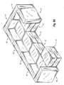
- FIGs 6a through 6i illustrate different configurations of furniture assemblies utilizing bases 12 and transverse members 14, as the case may be, according to the present invention.
- each of the bases 12 shown in Figures 6a-6j have substantially the same dimensions as each of the other bases 12 shown therein, such that the bases 12 are interchangeable
- each of the transverse members 14 shown in Figures 6a-j have substantially the same dimensions as each of the other transverse members 14, such that the transverse members 14 are interchangeable.
- Figure 6a illustrates the use of a base 12 alone, by itself, to form an ottoman.
- Figure 6b illustrates the configuration of a bench, wherein two bases 12 are utilized and coupled together to form the bench.
- Figure 6c illustrates the configuration of an arm chair. In this embodiment, three transverse members 14 are utilized in connection with one base 12 so as to form the chair.
- Figure 6d illustrates the configuration of a chaise formed by two bases 12 and two transverse members 14 coupled together.
- couplers 15 can be used for each of the furniture configurations illustrated in Figures 6a-j .
- a single coupler 15 can be employed to couple base 12 to base 12 to form the bench of Figure 6b .
- first and second couplers 15 are employed to couple base 12 to base 12 to form the bench of Figure 6b .
- First, second and third couplers 15 are employed to couple respective transverse members 14 to base 12 to form the chair of Figure 6c .
- a single coupler 15 is employed to couple base 12 to base 12 in the chaise of Figure 6d
- second and third couplers 15 are used to couple respective transverse members 14 to one of the bases 12.
- the assemblies shown in Figures 6e-6j can similarly be coupled together through the use of couplers, such as coupler 15 to couple respective bases 12 and transverse members 14 together to form a desired configuration.
- Figure 6e illustrates a sofa formed from two bases 12 and four transverse members 14.
- Figure 6f illustrates a deep love seat, utilizing two bases 12 and four transverse members 14 detachably coupled together.
- Figure 6g illustrates the configuration of a sectional having six bases 12 and seven transverse members 14 coupled thereto.
- Figure 6h illustrates a configuration of a twister design, utilizing four bases 12 and four transverse members 14.
- Figure 6i illustrates the configuration of a playpen, utilizing four bases 12 and eight transverse members 14 detachably coupled to form the playpen, as illustrated in Figure 6i .
- Figure 6j illustrates the configuration of a bed, wherein six bases 12 are coupled together to form the bed and two transverse members 14 are coupled to two of the bases 12 to form the headboard of the bed.
- the six bases 12 are configured and arranged so as to enable a user to sleep thereon.
- a coupler 15 is employed to forma connection between each base 12 and transverse member 14 and/or other base 12 in the embodiments shown in Figures 6a-6j .
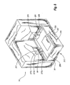
- Figure 7 illustrates an alternative embodiment of base 112.
- frame 136 is configured such that support member 158 is angled. Angling of support member 158 allows a user to naturally recline while sitting on base 112.
- cushioning member 140e is a wedge shaped piece of foam configured to be received within recess 144 of frame assembly 116 to form a flush top surface.
- cushion 118 comprises multiple foam pieces to form a cushion that will facilitate the reclining of a user sitting thereon.
- cushion 118 can comprise a first foam wedge piece 120 and a second foam wedge piece 122 positioned adjacent to first foam wedge piece 120 to form a rectangular solid.
- a layer of memory foam 124 can be positioned on second foam wedge 122 so as to form a cushion 118 a user can sit upon.
- layer of memory foam 124 provides additional comfort to a user sitting on base 112.
- First foam piece 120 can be denser than second foam piece 122 so as to allow second foam piece 122 to give more when pressure is applied thereon, such as when a user is sitting on cushion 118.
- the discrepancy in density of the two foam wedges 120,122 provides for the natural reclining of a consumer when the consumer sits on cushion 118.
- FIG. 8 illustrates another embodiment of the base and various couplers.
- base 212 comprises a frame assembly 216 having a frame 236 and a plurality of mounting plates 261 mounted on frame 236.
- Frame 236 comprises a support member 258 upon which a cushion or cushioning member can be mounted.
- Support member 258 comprises a solid, substantially flat surface. In this embodiment, support member 258 does not comprise grooves.
- coupler 15 is utilized with base 212, first end 15a of coupler 15 can be shortened so as to not interfere with support member 258.
- base 12 and base 212 can be employed in the same furniture assembly.
- Mounting plates 261 are reinforced, substantially flat surfaces configured and positioned to enable the convenient, manual, detachable coupling of base 212 to transverse member 14 by coupler 15, a flared coupler 215, and/or a ratcheting coupler 217.
- Mounting plates 261 are positioned along the periphery of frame 236 in a similar fashion as grooves 62a-f are positioned in relation to base 12. The respective positioning of mounting plates 261 along the periphery of base 212 enables the quick and efficient positioning of transverse member 14 in relation to base 212 so as to form a desired furniture assembly.
- Mounting plates 261 are mounted on the inner surface of frame 236 and/or on the transverse member 14.
- Flared coupler 215 comprises a U-shaped member having terminating, flared ends that curve outwardly with respect to each other. The flared ends are curved so as to facilitate the insertion of coupler 215 into transverse member 14 and base 212. Flared coupler 215 can be utilized in the same or similar fashion as coupler 15 to manually, detachably couple base 212 to transverse member 14 and/or another base 212, such as shown in Figures 6b-6j . The lengths of the legs of flared coupler 215 may be substantially the same, for example, or may be different.
- ratcheting coupler 217 comprises a first portion 217a, a second portion 217b and a ratcheting portion 217c configured to enable the manual, detachable coupling of base 212 to transverse member 14.
- First portion 217a is configured to be selectively received within and secured by ratcheting portion 217c.
- Ratcheting portion 217c is coupled to second portion 217b and configured to selectively receive and secure first portion 217a therein.
- Ratcheting portion 217c is further configured to advance first portion 217a within ratcheting portion 217c as ratcheting portion 217c is actuated.
- Ratcheting portion 217c is further configured to selectively release First portion 217a therefrom to enable a consumer to quickly and efficiently detach first portion 217a from second portion 217b.
- first portion 217a is coupled to base 212 and second portion 217b is coupled to transverse member 14.
- first portion 217a can be selectively coupled to any mounting plate 261.
- First portion 217a is secured to second portion 217b so as to manually, detachably couple base 212 to transverse member 14.
- Ratcheting coupler 217 can be utilized with base 12.
- a useful example of a type of ratcheting coupler 217 is the coupler commonly utilized in connection with snowboard bindings.
- the ratcheting coupler commonly employed with snowboard bindings includes a first strap having a plurality of grooves formed perpendicular to the length of the strap, and an associated second strap having a ratcheting type mechanism coupled thereto.
- the first strap can be received within and secured by the ratcheting mechanism.
- the ratcheting mechanism includes a lever that when grasped and actuated will advance the first strap within the ratcheting mechanism by contact with the grooves in the first strap.
- a means is provided for releasing the first strap from the ratcheting mechanism, such as a button or an additional lever, such that actuation of the button or lever enables a consumer to easily remove the first strap from the ratcheting mechanism. As such, the first strap is secured to the second strap.
- a storage compartment 257 can be utilized in connection with frame 236 to store couplers or other items, as the consumer so chooses.
- Storage compartment 257 can be sized and configured to accommodate numerous and various couplers therein.
- Storage compartment 257 can be closed off by the use of a trapped door 259 formed in support member 258.
- Storage compartment 257 provides a useful and convenient storage area in which to store some of the consumer's items and/or hardware associated with the furniture assembly.
- Coupler 15, flared coupler 215, leg couplers 34-35 and ratcheting coupler 217 are examples of couplers that manually, detachably couple a base 212 (or 12) to transverse member 14 and/or another base 212 (or 12).
- the coupler could be a mechanical hook and latch system.
- the coupler can be a clasp, such as a clasp used on watches.
- coupler can be a variety of different types of quick release systems.
- the couple can comprise a plurality of magnets.
- the couple can comprise snaps.
- coupler can be a strap and buckle configuration.
- one end of a first strap is coupled to transverse member 14 and the other end of the first strap has a female portion of a buckle coupled thereto.
- One end of the second strap is coupled to base 12 and the other end is slidably received within the male portion of the buckle, such that when the male portion is received within the female portion, the second strap can be pulled to cinch the pieces together.
Landscapes
- Health & Medical Sciences (AREA)
- General Health & Medical Sciences (AREA)
- Nursing (AREA)
- Life Sciences & Earth Sciences (AREA)
- Engineering & Computer Science (AREA)
- Wood Science & Technology (AREA)
- Combinations Of Kitchen Furniture (AREA)
- Furniture Connections (AREA)
- Special Chairs (AREA)
- Mattresses And Other Support Structures For Chairs And Beds (AREA)
Description
- The invention relates to the field of furniture. Particularly, the invention relates to a modular furniture assembly.
- A variety of shapes and sizes of furniture have been developed over the years to provide comfort and decoration. Consumers appreciate furniture that can serve multiple purposes and withstand the wear of everyday use without requiring much attention. Thus, what is desirable is furniture that is versatile, durable and relatively maintenance free.
- Once purchased, consumers expect furniture that is already assembled or can be easily assembled. Once assembled, however, most furniture cannot be easily disassembled. Most furniture is assembled using nails, staples, epoxy or some other type of fastener. Further, various types of furniture have upholstery covering the fastener thus making it difficult to disassemble the furniture. This presents a challenge for consumers, especially when the furniture needs to be transported from one location to another.
- Additionally, once assembled, consumers appreciate furniture which can be readily cleaned. Most upholstery is secured to the furniture through the use of nails and/or staples, thus making it difficult to remove and clean when soiled or stained.
- One aspect that makes furniture cost-prohibitive is shipping and packaging. For example, a large piece of furniture requires a large amount of space during shipping. The non-solid shape of most furniture makes it difficult to maximize the space utilized when packaging and shipping furniture. This adds increased costs of shipping due to the amount of space the furniture requires, regardless if the furniture fills all or most of the required space.
- Another aspect that makes furniture cost-prohibitive is the difficulty in stacking furniture. When large pieces of furniture are stacked, damage frequently occurs to the furniture on the bottom of the stack. This damage may result from the shape and non-solid nature of the packaged furniture. Even when furniture is disassembled and boxed in order to facilitate stacking, often there is still much wasted space. The wasted space not only increases the cost of shipping, but also provides for a less stable base for which to stack other pieces of furniture.
- For those consumers who cannot afford many pieces of furniture, it is also desirable to have furniture which can provide multiple functions. For example, a futon bed serves the function of both a bed and a couch. However, futon beds are bulky, and thus subject to the cost factors described above. In addition, futon mattresses are often thin and uncomfortable both as a couch and as a bed.
- An example of a prior art modular furniture assembly is disclosed in
US5,867,849 (Pontrello ). This document shows a series of connected units which can, for example, be unfolded to form a single bed arrangement. - The invention relates to a modular furniture assembly that can be assembled, disassembled, rearranged, moved and cleaned in a quick and efficient manner with minimal effort.
- In accordance with the present invention, there is provided a modular furniture assembly comprising:
- a base configured such that the base has a length (x) and a width (y);
- a transverse member configured such that the transverse member has a length (x') and a width (z);
wherein the base and the transverse member have a defined spatial relationship, the defined spatial relationship being: - the length (x) of the base is substantially equal to the length (x') of the transverse member, and
- the length (x) of the base is substantially equal to the sum of the width (y) of the base and the width (z) of the transverse member, such that different furniture configurations can be formed.
- Optionally, the base comprises at least one substantially flat portion that abuts a substantially flat portion of the transverse member.
- Optionally, the modular furniture assembly further comprises:
- a removable liner adapted to detachably cover the base, the base liner having a length (x) and a width (y);
- a removable liner adapted to detachably cover the transverse member, the transverse member liner having a length (x') and a width (z);
- Optionally, a frame of the base and a frame of the transverse member each have a corresponding aperture therein that receives a portion of a coupler therein.
- Optionally, the modular furniture assembly further comprises:
- a second transverse member having substantially the same configuration as the first transverse member such that the transverse members are interchangeable, and such that a variety of different furniture assemblies can be formed.
- Optionally, the modular furniture assembly further comprises:
- a third transverse member having the same configuration as the first and second transverse members such that the transverse members are interchangeable and such that the first, second and third transverse members can each be used as at least one of a back rest and an arm rest.
- Optionally, the base comprises:
- a frame assembly; and
- a cushion mounted on the frame assembly.
- Optionally, the length (x') of the transverse member is a length in a horizontal plane; the length (x) of the base is a length in said horizontal plane; the width (y) of the base is a width in said horizontal plane; and the width (z) of the transverse member is a width in said horizontal plane.
- Optionally, the height (h') of the transverse member is substantially greater than the height (h) of the base.
- Optionally, the height (h') of the transverse member is perpendicular to length (x') of the transverse member.
- Optionally, the modular furniture assembly further comprises:
- a second transverse member, wherein each transverse member has a length (x') and a width (z) in said horizontal plane and wherein the height (h') of each transverse member is substantially greater than the height (h) of the base, and wherein the height (h') of each transverse member is perpendicular to the length (x') of each transverse member; and further comprising
- a plurality of couplers configured to detachably couple respective transverse members to the base, wherein each of the transverse members has an aperture that receives a portion of a coupler, each of the apertures being formed at the same position in each of the transverse members, wherein a frame of the base and a frame of each of the transverse members have a corresponding aperture therein that receives a portion of a coupler for coupling a transverse member to the base.
- Optionally, the base has a frame having an aperture in a top portion thereof and wherein the transverse member has a frame having an aperture in a side portion thereof and wherein a coupler is receivable downwardly into the aperture in the top portion of the base frame and into the aperture in the side portion of the transverse member frame to thereby sandwich a portion of the base and a portion of the transverse member between portions of the coupler.
- Optionally, the modular furniture assembly further comprises:
- a coupler having a U-shaped coupling portion such that the coupler sandwiches portions of the base member and the transverse member between portions of the coupler to thereby detachably couple the base member to the transverse member.
- Optionally, the modular furniture assembly further comprises:
- at least one foot coupler configured to facilitate the detachable coupling of the transverse member to the base.
- Optionally, the modular furniture assembly further comprises:
- a first coupler that substantially prevents the transverse member from moving in at least a first direction; and a second coupler that substantially prevents the transverse member from moving in at least a second direction.
- It will be appreciated that the base may serve as a support surface on which a user can sit, and the transverse member may act as a resting surface for a user's back or arm. The coupler is configured to allow a user to quickly couple or decouple the transverse member and the base with minimal effort without the use of a tool. The ease of coupling a transverse member to the base enables a consumer to easily form many configurations of furniture assemblies.
- The base is configured such that it can be positioned adjacent the transverse member in a variety of ways and detachably coupled thereto so as to provide a variety of configurations of modular furniture assemblies. As such, many bases and transverse members can be utilized to form a variety of different furniture assemblies. For instance, one embodiment utilizes one base and one transverse member coupled together to form a chair. In another embodiment, three transverse members are coupled to one base to form an arm chair. Furthermore, the base(s) and transverse member(s) can be placed in a variety of different positions so as to form a variety of different chairs.
- Accordingly, it will be appreciated that the aforementioned defined spatial relationship enables the convenient formation of a variety of different types, sizes and configurations of furniture assemblies.
- In use, one or more bases having a substantially similar configuration can be employed with one or more transverse members having a substantially similar configuration. The standardized configuration of bases and transverse members enables a user to form a variety of different types and configurations of furniture assemblies. This also makes manufacturing convenient because a manufacturer can produce a series of bases that have a substantially similar configuration and a series of transverse members that have a substantially similar configuration, then arrange (or allow the end user to arrange) the bases and transverse members into a variety of configurations to form different types of furniture. The user can purchase one or more bases having the same configuration and one or more transverse members having the same configuration, then combine them to form a number of different furniture assemblies.
- For example, a first base and a first transverse member can be employed to form a chair having a back rest. Second and third transverse members having a substantially similar configuration as the first transverse member can be added to form an armchair. Optionally, a couch can be formed by adding: (i) a second base having a substantially similar configuration as the first base; and (ii) second, third and fourth transverse members having a substantially similar configuration as the first transverse member. An endless variety of furniture assemblies can be formed by utilizing bases and transverse members having standardized, substantially similar configurations, respectively.
- The spatial relationship further enables the manufacturer to proportionately size the bases and transverse members to form furniture assemblies for different sizes of individuals. For example, the bases and transverse members can be proportionately sized to form furniture assemblies for children. Likewise, the bases and transverse members can be proportionately sized to form furniture assemblies for adults, or even oversized adults. As such, the bases(s) and transverse members(s) of the present invention can be utilized to form a variety of sizes of furniture.
- The configuration of the base and transverse member of the present invention provides many benefits to both the consumer and retailer. For example, the present invention enables the consumer to have a piece of furniture in a remote location where previously other pieces of furniture could not be moved due to their bulkiness and/or size. The present invention is easily disassembled, thus enabling a consumer to locate the base(s) and/or transverse member(s) in an otherwise inaccessible location and then assemble them to form a furniture assembly. Furthermore, the present invention enables a manufacturer and/or retailer to stock two pieces of furniture, i.e. a base and a transverse member. This is advantageous for shipping and storing. For instance, the manufacturer and/or retailer is only required to store two primary pieces and is able to stack the bases or transverse members having the same respective configuration on top of each other when loading and unloading from freight. Likewise, the bases and transverse members can be stacked in an orderly fashion in storage.
- In addition, the transverse member and the base may include removable outer liners. The removable outer liners allow a consumer to easily launder the furniture assembly. Further, utilizing a removable outer liner allows a consumer to interchange liners of different shades and styles to create a unique and customized furniture assembly. Thus, the furniture assembly of the present invention is versatile, modular, interchangeable and convenient.
- These and other objects and features of the present invention will become more fully apparent from the following description and appended claims, or may be learned by the practice of the invention as set forth hereinafter.
- To further clarify the above and other advantages and features of the present invention, a more particular description of the invention will be rendered by reference to specific embodiments thereof which are illustrated in the appended drawings. It is appreciated that these drawings depict only typical embodiments of the invention and are therefore not to be considered limiting of its scope. The invention will be described and explained with additional specificity and detail through the use of the accompanying drawings in which:
-
Figure 1 is a perspective view illustrating a modular furniture assembly having a base coupled to a transverse member to form a chair; -
Figure 2 is an exploded cutaway view illustrating the base; -
Figure 3 is a perspective view of the traverse member; -
Figure 4a is a perspective view of the coupler and the foot couplers; -
Figure 5a is a perspective view illustrating how the modular furniture assembly is assembled; -
Figure 5b is a perspective view illustrating the positioning of the coupler in relation to the transverse member and the base; -
Figure 5c is a cross-sectional view of the assembled modular furniture assembly; -
Figure 6a illustrates a modular furniture assembly in the configuration of an ottoman;Figure 6b illustrates a modular furniture assembly in the configuration of a bench; -
Figure 6c illustrates a modular furniture assembly in the configuration of an arm chair; -
Figure 6d illustrates a modular furniture assembly in the configuration of a chaise; -
Figure 6e illustrates a modular furniture assembly in the configuration of a love seat; -
Figure 6f illustrates a modular furniture assembly in the configuration of a deep sofa; -
Figure 6g illustrates a modular furniture assembly in the configuration of a sectional; -
Figure 6h illustrates a modular furniture assembly in the configuration of a twister; -
Figure 6i illustrates a modular furniture assembly in the configuration of a playpen; -
Figure 6j illustrates a modular furniture assembly in the configuration of a bed; -
Figure 7 is an exploded perspective view illustrating an alternative embodiment of the base; and -
Figure 8 illustrates another embodiment of the base and coupler. - The invention relates to a modular furniture assembly that can be assembled, disassembled, rearranged, moved and cleaned in a quick and efficient manner with minimal effort. The invention further relates to a modular furniture assembly that has a spatial relationship that enables a user to form a number of different furniture assemblies. In an exemplary embodiment, the modular furniture assembly comprises a base, at least one transverse member and a coupler configured to detachably couple the transverse member to the base so as to form a chair. The configuration of the base and transverse member enable a user to form a number of different furniture assemblies.
- The base serves as a support surface on which a user can sit, and the transverse member acts as a resting surface for a user's back or arm. The base is configured such that transverse member can be positioned adjacent the base in a variety of positions and detachably coupled thereto to form different types of furniture assemblies. The coupler is configured to allow a user to quickly couple or decouple the transverse member and the base with minimal effort without the use of a tool. The ease of coupling a transverse member to the base provides for the capability of easily forming many configurations of furniture assemblies. Many bases and transverse members can be utilized to form a variety of differing furniture assemblies. In addition, the base and transverse member can be proportionately sized to accommodate different sizes of individuals. As such, a variety of types, sizes and configurations of furniture can be made in a quick and convenient fashion by utilizing the present invention.
-
Figure 1 illustrates an exemplary embodiment of amodular furniture assembly 10. In the illustrated embodiment,modular furniture assembly 10 comprises abase 12 and atransverse member 14 detachably coupled tobase 12 by a coupler 15 (Figure 4 ).Base 12 andtransverse member 14 are adapted to be detachably coupled to each other in a variety of ways and configurations so as to form a variety of unique and custom furniture assemblies. Further,base 12 andtransverse member 14 are sized and configured according to a defined spatial relationship. The defined spatial relationship, as described more fully hereinafter, betweenbase 12 andtransverse member 14 enables: (i) the convenient formation of a variety of different types of furniture assemblies; (ii) the convenient formation of a variety of different configurations of furniture assemblies; and (iii) a manufacturer to proportionately size the bases and transverse members for different sizes of individuals, such as for children or for adults. -
Base 12 is configured to provide a comfortable sitting surface for a consumer.Base 12 is also configured to be easily disassembled for rearranging, moving, storing and/or shipping. In this embodiment,base 12 comprises aframe assembly 16, acushion 18 and a plurality offeet 20a-d mounted onframe assembly 16.Frame assembly 16 is configured to support the weight of a consumer while the consumer is sitting onbase 12.Cushion 18 is configured to be mounted onframe assembly 16 so as to provide a useful and comfortable sitting area for a consumer.Cushion 18 can be easily mounted on or removed fromframe assembly 16. -
Feet 20a-d are coupled to the underside offrame assembly 16.Feet 20a-d can be coupled toframe assembly 16 in a variety of ways. In one embodiment,feet 20a-d are coupled by screws. In this embodiment,feet 20a-d can be easily coupled to and/or removed fromframe assembly 16 so as to facilitate ease in packaging, shipping, storing, moving and/or replacingfeet 20a-d. However,feet 20a-d can be coupled toframe assembly 16 in a more permanent fashion, such as with a nail, an epoxy or glue, or any combination thereof.Feet 20a-d facilitate the coupling oftransverse member 14 tobase 12 when used in connection with a foot coupler, such asfoot coupler 34 and/or 34a.Feet 20a-d are further configured to support the weight of a consumer and to elevatebase 12 above the floor. Whenfeet 20a-d are coupled to frameassembly 16 by screws, the removability offeet 20a-d in conjunction with the removability ofcushion 18 enablesbase 12 to be easily disassembled for rearranging, moving, storing and/or shipping. -
Base 12 includes a plurality of abuttingsurfaces 26a-d that are configured to be positionable adjacent to and abut with an abuttingsurface 28 oftransverse member 14. As will be discussed more fully herein,base 12 is configured such thattransverse member 14 can be positioned adjacent anyabutting surface 26a-d to form a variety of different furniture assemblies. - In the illustrated embodiment,
base 12 andtransverse member 14 have a defined spatial relationship. The spatial relationship betweenbase 12 andtransverse member 14 enable the formation of a variety of different types, sizes and configurations of furniture assemblies. In this embodiment, base has a length (x) and a width (y), wherein the length (x) ofbase 12 is greater than the width (y) ofbase 12, andtransverse member 14 has a length (x') and a width (z), wherein the length (x') oftransverse member 14 is greater than the width (z) oftransverse member 14. In this embodiment,base 12 andtransverse member 14 are configured such that the length (x) ofbase 12 is substantially equal to the length (x') oftransverse member 14 and the length (x) ofbase 12 is substantially equal to the sum of the width (y) ofbase 12 and the width (z) oftransverse member 14. As such, (x) is substantially equal to (y) + (z). This relationship of the length (x) ofbase 12 being substantially equal to the sum of the width (y) ofbase 12 and width (z) oftransverse member 14 is the defined spatial relationship betweenbase 12 andtransverse member 14. Furthermore, the height (h') oftransverse member 14 is substantially greater than the height (h) ofbase 12, such thattransverse member 14 can be conveniently employed as a backrest or armrest whilebase 12 is employed as a seat. - This defined spatial relationship enables a user to conveniently form a variety of different types of furniture assemblies. For example, in the illustrated embodiment, a
first base 12 and a firsttransverse member 14 are utilized to form a chair. Second and thirdtransverse members 14 having a substantially similar configuration as the firsttransverse member 14 can be added to form an arm chair having a first arm rest and a second arm rest, as illustrated inFigure 6c . As used herein, the phrase substantially similar configuration can mean that the bases and/or transverse members are respectively sized and configured so as to be interchangeable. Optionally, a couch can be formed by adding: (i) asecond base 12 having a substantially similar configuration as thefirst base 12; and (ii) a second, third and fourthtransverse member 14 having a substantially similar configuration as the firsttransverse member 14, as illustrated inFigure 6e and Figure 6f . This ability to add base(s) and/or transverse member(s) to form different types of furniture is how the defined spatial relationship enables a user to conveniently form a variety of different types of furniture. - As further shown in
Figures 6e-f , the defined spatial relationship enables a user to conveniently form a variety of different configurations of furniture assemblies. For example, the couches formed by utilizing twobases 12 and fourtransverse members 14 can be arranged so as to form a love seat, as illustrated byFigure 6e , or a deep sofa, as illustrated byFigure 6f . The love seat ofFigure 6e and the deep sofa ofFigure 6f employ thesame bases 12 and the sametransverse members 14, but are arranged differently. Thus, the defined spatial relationship of the present invention enables a user to conveniently form a variety of different configurations of furniture assemblies. - The defined spatial relationship also enables a manufacturer to manufacture different sizes of bases and transverse members so as to accommodate different sizes of individuals. For example, a manufacturer can manufacture a base and a transverse member such that when the base and transverse member are detachably coupled together a furniture assembly is formed that is sized for a child, but may be too small for an adult to use comfortably. On the other hand, a manufacturer, utilizing the spatial relationship, can enlarge the size of the base(s) and transverse member(s) such that when the base(s) and transverse member(s) are coupled together a furniture assembly is formed that is sized to accommodate an adult comfortably. As such, the spatial relationship between
base 12 andtransverse member 14 enables the formation of a variety of different sizes of furniture assemblies. - With continued reference to
Figure 1 ,transverse member 14 is configured to provide lateral support to a consumer whenbase 12 is coupled thereto.Transverse member 14 can be positioned adjacent anyabutting surface 26a-d ofbase 12 to form a variety of furniture assemblies. A plurality offeet 30a-b are coupled to the underside oftraverse member 14.Feet 30a-b are configured to facilitate the coupling oftransverse member 14 tobase 12.Feet 30a-b are further configured to support the weight of a consumer and to elevatetransverse member 14 above a floor on whichtransverse member 14 is positioned.Feet 30a-b can be coupled totransverse member 14 in a similar fashion asfeet 20a-d are coupled tobase 12. - In one embodiment,
feet 30a-b are each positioned such that each are offset from the front and back surfaces and respective adjacent side surfaces oftransverse member 14 an equal distance, the "offset distance." For example, if the width (z) of transverse member is ten inches, the offset distance is five inches. Thus,feet 30a-b are each positioned five inches from the front surface and five inches from the back surface of transverse member 14 (i.e., in the middle of the front and back surfaces), and are each positioned five inches from respective adjacent side surfaces oftransverse member 14. Similarly,feet 20a-d ofbase 12 are each positioned such that each are offset from respective adjacent abuttingsurfaces 26a-d the offset distance. As such, in one such embodiment: (i)foot 20a is offset from both abuttingsurface 26a and abuttingsurface 26b the offset distance; (ii)foot 20b is offset from both abuttingsurface 26b and abuttingsurface 26c the offset distance; (iii)foot 20c is offset from both abuttingsurface 26c and abuttingsurface 26d the offset distance; and (iv)foot 20d is offset from both abuttingsurface 26d and abuttingsurface 26a the offset distance. - In the illustrated embodiment,
modular furniture assembly 10 further includes multiple foot couplers 34-35, which may be identical, for example. Foot couplers 34-35 are adapted to facilitate the coupling oftransverse member 14 tobase 12. Foot couplers 34-35 are further adapted to provide support tobase 12 andtransverse member 14 when coupled thereto.Foot coupler 34 utilizesfoot 20d ofbase 12 andfoot 30a oftransverse member 14 which is adjacent to foot 20d of base to facilitate coupling oftransverse member 14 tobase 12. Likewise,foot coupler 35 utilizesfoot 20c ofbase 12 andadjacent foot 30b oftransverse member 14 to facilitate coupling oftransverse member 14 tobase 12. - In the illustrated embodiment, traverse
member 14,frame assembly 16 and cushion 18 each include a selectively removableouter liner outer liners outer liners -
Figure 2 illustrates an exploded cutaway view ofbase 12. In the illustrated embodiment,frame assembly 16 comprises aframe 36 and acushion assembly 38 associated withframe 36.Frame 36 is configured and arranged so as to support the weight of a consumer utilizingmodular furniture assembly 10.Frame 36 can comprise a plurality of structural members made from wood, metal, composite, plastic, or any other structural material or combination thereof. As will be appreciated by one of ordinary skill in the art, the structural members that make upframe 36 and their orientation can be modified and/or rearranged to meet different specifications, such as size and/or weight requirements. - In the illustrated embodiment,
frame assembly 16 further comprises asupport member 58 that is mounted onframe 36.Support member 58 is positioned in arecess 44 offrame 36. For example, in one embodiment,support member 58 is mounted on fourupstanding posts 59 and/orupstanding slats 61 positioned withinrecess 44.Support member 58 comprises a sheet of material, such as wood or some other structural material, having a plurality ofgrooves 62a-f formed therein.Grooves 62a-f are positioned along the perimeter ofsupport member 58 and are sized so as to allow a portion ofcoupler 15 to be received therein.Grooves 62a-f are positioned insupport member 58 so as to provide a variety of coupling locations onbase 12 for the coupling oftransverse member 14 tobase 12 and/or coupling ofbase 12 to anotherbase 12. - When
support member 58 is positioned inrecess 44 offrame 36,grooves 62a- f each form a portion of an aperture in frame assembly 16 (seeFigure 5b ). In the illustrated embodiment, twogrooves 62a-b,d-e are positioned adjacent respective abuttingsurfaces 26a,c, and onegroove 62c,f is positioned adjacent respective abuttingsurfaces 26b,d. Twogrooves 62a-b,d-e are respectively positioned adjacent respective abuttingsurfaces 26a,c in order to enable the positioning oftransverse member 14 in two different locations adjacent each abuttingsurfaces 26a,c. The ability to positiontransverse member 14 in multiple locationsadjacent base 12 enables the formation of different furniture configurations. As such,transverse member 14 can be positioned and coupled tobase 12 bycoupler 15 in at least six different positions in relation tobase 12. This can be accomplished, for example, by aligning an aperture 64 (Figure 3 ) oftransverse member 14 with any ofgrooves 62a-f and placing a portion ofcoupler 15 in each ofaperture 64 and the desired aperture offrame assembly 16. - Thus, the configuration and positioning of
grooves 62a-f insupport member 58 facilitates different positioning oftransverse member 14 with respect tobase 12, such that a variety of shapes and configurations of modular furniture assemblies can be made. For example,aperture 64 oftransverse member 14 can be aligned with any ofgrooves 62a-f. Once aligned, coupler 15 (Figure 4 ) can be used to connectbase 12 totransverse member 14, as illustrated inFigure 5b . - Similarly,
grooves first base 12 can be aligned with eithergroove second base 12 so as to couple two bases together, as illustrated inFigure 6b . The versatility of being able to couplemultiple bases 12 andtransverse members 14 together enables the ability to make a variety of different and unique furniture assemblies. Afirst base 12 can be coupled to asecond base 12 by aligning an aperture of thefirst base 12 with an aperture of thesecond base 12 and placing a portion ofcoupler 15 in the aperture of thefirst base 12 and the aperture of thesecond base 12.Figures 6a-6j illustrate various examples of furniture assemblies that can be formed frombases 12 andtransverse members 14 by employingcoupler 15 to couple thebases 12 to thetransverse members 14 and/orbases 12 as shown therein. - Returning now to
Figure 2 ,cushion assembly 38 comprises a plurality ofcushioning members 40a-c that connect to the outer surface offrame 36 and anadditional cushioning member 40d that is mounted uponsupport member 58 whensupport member 58 is mounted withinframe 36. Cushioningmembers 40a-c,d are configured to provide a cushioning surface for a consumer utilizingmodular furniture assembly 10. Cushioning offrame 36 withcushioning assembly 38 provides for a more comfortable piece of furniture. - Cushioning
members 40a-c each comprise a rectangular piece of foam adapted to be positioned on respective outside surfaces offrame 36 so as to cover the outside portions offrame 36. An additional rectangular piece of foam employed to cushion the frame surfaceadjacent abutment surface 26c is not shown in the illustration ofFigure 2 .Such cushioning members 40a-c (including the additional pieceadjacent abutment surface 26c) can comprise a variety of types of foam in order to accommodate the desired resilience and padding offrame assembly 16;such cushioning members 40a-c may comprise a single piece of foam or can comprise a combination of foam layers, such as a layer of memory foam positioned over a layer of polyurethane foam. In the illustrated embodiment,cushioning members 40a-c are covered by aninner liner 46. - In this embodiment, cushioning
member 40d also comprises a piece of foam covered by aliner 42. Cushioningmember 40d is configured to be positionable withinrecess 44 offrame 36 on top ofsupport member 58. The foam piece of cushioningmember 40d can comprise a single piece of polyurethane foam, or a combination of different types of foams. For example, cushioningmember 40d can comprise a single piece of polyurethane foam and a similarly shaped piece of memory foam positioned on top of the single piece of polyurethane foam to form the cushioningmember 40d. Cushioningmember 40d is configured to facilitate a comfortable sitting surface for a consumer utilizingmodular furniture assembly 10. -
Liner 42 andinner liner 46 are configured to cover and provide protection forcushioning members 40a-d offrame assembly 16.Liner 42 andinner liner 46 can comprise a fabric material that is either water permeable or impermeable. An advantage of a water impermeable liner is that the liner will help protectframe 36 andcushioning members 40a-d in the event a liquid, such as a soda, is spilled onframe assembly 16. -
Frame assembly 16 also includes removableouter liner 22. Removableouter liner 22 is configured to be utilized withframe assembly 16 in order to provide additional protection forframe 36 andcushioning members 40a-c, and for aesthetics. Removableouter liner 22 is mounted oninner liner 46 so as to cover exposed portions ofinner liner 46 whencushion 24 is mounted thereon. - In the illustrated embodiment,
outer liner 22 is detachably coupled toframe assembly 16 through the means of aremovable securing mechanism 48, such as a hook and pile mechanism, e.g. VELCRO. In this manner,outer liner 22 can be selectively removed and laundered in the event thatouter liner 22 becomes soiled and/or stained. Theremovable securing mechanism 48, e.g. VELCRO, also facilitates a consumer to easily, quickly and efficiently reattachouter liner 22 toinner liner 46 offrame assembly 16. In addition, the selective removability ofouter liner 22 also facilitates a consumer being able to mix and match various styles, design and configurations of outer liners ofmodular furniture assembly 10 to create a customized and unique modular furniture assembly according to their desires and taste. - As indicated previously,
base 10 includes a plurality of abuttingsurfaces 26a- d. In the illustrated embodiment, abuttingsurfaces 26a-d are a respective, substantially flat surface configured to be positioned adjacent and abut the substantially flat abuttingsurface 28 oftransverse member 14. Abuttingsurface 28 oftransverse member 14 is configured to correspond with at least one of abuttingsurface 26a-d ofbase 12 whenbase 12 is placed in an abutting relationship withtransverse member 14. In this manner,coupler 15 can be utilized to coupletransverse member 14 tobase 12.Cushion 18 is configured to be positioned and mounted onframe assembly 16 so as to formbase 12. -
Cushion 18 is sized such that the perimeter ofcushion 18 is substantially equal to the perimeter offrame assembly 16. In the illustrated embodiment,cushion 18 comprises a piece offoam 50 covered by aninner liner 52.Foam piece 50 comprises a single piece of foam having a sufficient resilience and appropriate properties so as to provide a comfortable sitting surface when a user sits onmodular furniture assembly 10. However,foam piece 50 can comprise multiple types and configurations of foam pieces, such as a layer of polyurethane foam and a layer of memory foam mounted on the polyurethane foam layer. - As mentioned previously,
inner liner 52 coversfoam piece 50.Inner liner 52 can comprise a fabric material sufficient to substantially coverfoam piece 50.Inner liner 52 can be made of substantially the same material asinner liner 46 and/orliner 42. - In the illustrated embodiment,
inner liner 52 is covered by removableouter liner 24 so as to provide an aesthetically pleasing and comfortable cushioning surface for a user to sit upon. Removableouter liners outer liners outer liners - Removable
outer liners outer liners outer liners -
Figure 3 is a partial cut-away view illustratingtraverse member 14.Traverse member 14 is configured to be coupled tobase 12 so as to formmodular furniture assembly 10. As further illustrated inFigure 3 ,transverse member 14 is further configured to be positioned such that the longitudinal axis oftransverse member 14 is substantially transverse to the plane of a support surface on whichtransverse member 14 is mounted, such as the ground or a floor. - In the illustrated embodiment,
transverse member 14 comprises aframe assembly 54, an inner liner 56covering frame assembly 54, removableouter liner 32,feet 30a-b coupled to the underside offrame assembly 54, and anaperture 64 formed inframe assembly 54 to facilitate coupling oftransverse member 14 tobase 12. -
Frame assembly 54 is configured to provide lateral support to a user utilizingmodular furniture assembly 10.Frame assembly 54 is further configured to provide a comfortable surface upon which a consumer can rest upon. In the illustrated embodiment,frame assembly 54 comprises aframe 66 and acushion assembly 68.Frame 66 is configured to provide lateral support to a consumer sitting onmodular furniture assembly 10 whentransverse member 14 is coupled tobase 12.Frame 66 can comprise a plurality of structural members made from wood, metal, composite, plastic, or any other structural material or combination thereof. As will be appreciated by one of ordinary skill in the art, the structural members that make upframe 66 and their orientation can be modified and/or rearranged to meet different specifications, such as size and/or weight requirements. -
Cushion assembly 68 comprises a plurality ofcushioning members 70 and a wedge 72 in association withframe 66 to provide padded and comfortable surfaces. In the illustrated embodiment, wedge 72 comprises a piece of foam shaped like a wedge. Wedge 72 is configured to be mounted on an angled front surface offrame 66 so as to form a rectangular solid withframe 66. Cushioningmembers 70 are configured to surround andcover frame 66 and wedge 72. Cushioningmembers 70 comprise a piece of foam sized sufficiently to cover bothframe 66 and wedge 72. Coveringcushion assembly 68 are inner liner 56 and removableouter liner 32. Inner liner 56 can have similar characteristics asinner liners liner 42. Likewise, removableouter liner 32 can have similar characteristics asouter liners -
Aperture 64 is configured and positioned to facilitate coupling oftransverse member 14 tobase 12.Aperture 64 is centrally positioned adjacent abuttingsurface 28 oftransverse member 14 such that a variety of types and configurations of furniture assemblies can be formed.Aperture 64 is further positioned such thataperture 64 can be aligned with any ofgrooves 62a-f, such thattransverse member 14 can be positioned, in relation tobase 12, in a variety of ways.Aperture 64 extends throughframe assembly 54 and inner andouter liners 56, 32.Aperture 64 is sized sufficiently to allow a portion ofcoupler 15 to be received therethrough. -
Figure 4 is a perspective view illustrating certain couplers, includingcoupler 15 andfoot couplers Coupler 15 is configured to detachablycouple transverse member 14 tobase 12. In the illustrated embodiment,coupler 15 comprises an elongate, U-shaped member configured to be positionable withinaperture 64 oftransverse member 14 and one of thegrooves 62a-f ofsupport member 58, or when two bases are to be coupled together, within one of thegrooves 62a-f of thefirst base 12 and one of thegrooves 62a-f of thesecond base 12.Coupler 15 is further configured to engage the inner surfaces offrame 36 ofbase 12 andframe 66 oftransverse member 14, as shown inFigures 5b and5c , so as to sandwich a portion oftransverse member 14 and a portion ofbase 12 together between portions ofcoupler 15.Coupler 15 is configured to substantially prevent movement of the upper portion oftransverse member 14 in relation tobase 12. In this manner,coupler 15 substantially prevents movement oftransverse member 14 in at least a first direction with respect tobase 12. -
Coupler 15 can be made from a metal material, or some other structural material.Coupler 15 can include an aperture on the top surface ofcoupler 15 in order to facilitate the ease of insertion and removal ofcoupler 15.Coupler 15 has afirst leg 15a coupled to abody portion 15b having asecond leg 15c coupled thereto. In one embodiment,first leg 15a is longer thansecond leg 15c in order to facilitate convenient coupling ofbase 12 totransverse member 14 and to resist forces induced oncoupler 15. In another embodiment,first leg 15a is substantially the same length assecond leg 15c. -
Coupler 15 andfoot couplers transverse member 14 tobase 12. In the illustrated embodiment,foot coupler 34 comprises a block having a plurality ofapertures 74a-b formed there through.Apertures 74a-b are sized and configured to receive a foot ofbase 12 ortransverse member 14 therein.Apertures 74a-b offoot coupler 34 are sufficiently spaced apart, such that when a foot 30 fromtransverse member 14 is positioned inaperture 74a and a foot 20 frombase 12 is positioned inaperture 74b,transverse member 14 andbase 12 are adjacent and in contact one with another. - Foot couplers 34-35 are configured to substantially prevent movement of the bottom portion of
transverse member 14 in relation tobase 12. In this manner, foot couplers 34-35 substantially prevent movement oftransverse member 14 in at least a second direction with respect tobase 12. For example, in the embodiment illustrated inFigures 5a-c ,coupler 15 substantially prevents movement of the top portion oftransverse member 14 in at least a first direction, i.e., away frombase 12, while foot couplers 34-35 substantially prevent movement of the top portion oftransverse member 14 in at least a second direction, i.e., towardsbase 12. - Yet another embodiment of a
foot coupler 34a is shown inFigure 4 .Foot coupler 34a can function similarly tofoot coupler 34.Foot coupler 34a can replacefoot coupler 34, and has additional apertures for connecting additional feet. Thus,foot coupler 34a is configured to substantially prevent movement of the bottom portion oftransverse member 14 in relation tobase 12. -
Foot coupler 34a has fourapertures 74a-d, enablingfoot coupler 34a to be utilized in connection with coupling a base 12 to multipletransverse members 14 and/orbases 12 to form a furniture assembly as shown inFigures 6c-6j . For example, in the embodiment ofFigure 6c , onefoot coupler 34a may be employed to couple together one leg ofbase 12 to one leg of a firsttransverse member 14, which is positioned as a backrest, and one leg of a secondtransverse member 14, which is positioned as an armrest, while anotherfoot coupler 34a may be employed to couple together a second leg ofbase 12 to a second leg of the firsttransverse member 14 and a leg of a thirdtransverse member 14, which is positioned as another armrest. In this example, one aperture of eachfoot coupler 34a is not utilized, but the symmetrical configuration offoot coupler 34a enables the consumer to employfoot coupler 34a in a variety of different configurations of furniture assemblies. - As will be appreciated by one of ordinary skill in the art, the foot coupler of the present invention does not need to be restricted as to the number of apertures 74 formed therein. For example, a foot coupler of the present invention can be sized and configured to include an appropriate number of apertures so as to couple the feet of two
bases 12 and fourtransverse members 14 to facilitate the formation of a sofa. Optionally, a foot coupler can have any number of apertures necessary to couple a foot 20 ofbase 12 to a foot 30 oftransverse member 14 or foot 20 of anotherbase 12, and/or to couple a respective foot 20 ofmultiple bases 12 to a respective foot 30 of multipletransverse members 14, in any configuration. In one embodiment, apertures 74 can comprise a tapered opening so as to enable a consumer to more easily insert a foot therein. -
Figures 5a-c illustrate howmodular furniture assembly 10 is assembled. Illustrated in this embodiment,frame assembly 16 ofbase 12 is positioned againsttransverse member 14, such thataperture 64 is adjacent to and aligned withgroove 62f insupport member 58. Once aligned,coupler 15 is positioned withinaperture 64 oftransverse member 14 and pushed downward by the consumer so as to engage the inner flat surface offrame 66 oftransverse member 14 and the inner flat surface offrame 36 ofbase 12, as shown inFigures 5b and5c . In this manner,coupler 15 is connected to base 12 andtransverse member 14. - In addition,
foot 20d ofbase 12 is received intoaperture 74b offoot coupler 34, andfoot 30a oftransverse member 14 is received intoaperture 74a offoot coupler 34. Similarly,foot coupler 35, which may be similar or identical tofoot coupler 34, is utilized in a similar manner asfoot coupler 34, whereinfoot 20c is received intoaperture 74b offoot coupler 35 andfoot 30b is received intoaperture 74a offoot coupler 35. As such, utilization ofcoupler 15 and foot couplers 34-35 serve to detachably coupletransverse member 14 tobase 12 to formfurniture assembly 10 of the present invention. - As will be appreciated by one of ordinary skill in the art, the consumer can easily and quickly use
coupler 15 andfoot couplers detachably couple base 12 totransverse member 14 and/or anotherbase 12. For instance, the consumer does not require tools to connect or disconnectcoupler 15 tobase 12 andtransverse member 14. Since no tools are required, the consumer can manually connect or disconnectcoupler 15 andfoot couplers base 12 andtransverse member 14 and/or anotherbase 12. Thus, as used herein, the phrase "manually, detachably couple" can mean that coupler and foot couplers conveniently couple and decouplebase 12 andtransverse member 14 and/or anotherbase 12 without using a tool, such as a hammer or screwdriver, or some other mechanized machine. - Once
coupler 15 is connected to base 12 andtransverse member 14,cushion 18 can be placed onframe assembly 16 so as to formfurniture assembly 10. As will be appreciated by one who is skilled in the art,foot couplers coupler 15 are easily, manually disconnected and removed in order to disassemblemodular furniture assembly 10. -
Figure 5b is a perspective view ofmodular furniture assembly 10 illustratingcoupler 15 detachably couplingtransverse member 14 tobase 12. In this illustration,coupler 15 is received throughaperture 64 oftransverse member 14 and an aperture inbase 12. The aperture inbase 12 through whichcoupler 15 is received is formed bygroove 62f andframe 36. In this manner,coupler 15 is utilized to facilitate the coupling oftransverse member 14 tobase 12. In addition,foot coupler 34 is mounted onfeet foot coupler 35 is mounted onfeet -
Figure 5c illustrates a cross-sectional view ofmodular furniture assembly 10 whencoupler 15 and foot couplers 34-35 are connected to base 12 andtransverse member 14. As shown in the illustrated embodiment,coupler 12 sandwiches substantially flat portions offrame 36 and substantially flat portions offrame 66 whencoupler 12 is connected to base 12 andtransverse member 14.Coupler 15 is received inaperture 64 andgroove 62f when connected to base 12 andtransverse member 14.Foot coupler 35 is also illustrated showing how afoot 30b oftransverse member 14 and afoot 20c ofbase 12 are received infoot coupler 35. -
Modular furniture assembly 10 can be assembled and disassembled in a quick and efficientmanner utilizing base 12,transverse member 14,coupler 15 and foot couplers 34-35. Similarly, the ease of removingcoupler 15 and foot couplers 34-35 allows a consumer to easily dismantle or disassemblemodular furniture assembly 10 for moving and/or packing ofmodular furniture assembly 10. - For example, a consumer could purchase a base 12, a
transverse member 14, acoupler 15, and multiple foot couplers 34-35 and thereafter assemble them to form a modular furniture assembly having a back and a base, such as a chair. The consumer could easily assemble the modular furniture assembly by positioning thebase 12 adjacent thetransverse member 14, inserting thecoupler 15 to engage the frame of thetransverse member 14 and frame of thebase 12, and then position foot couplers 34-35 over the feet of opposing sides of thebase 12 and thetransverse member 14 to form a secure and comfortable chair, such as shown inFigure 1 . In the event that the consumer needs to move the chair, the chair is easily disassembled by removing the coupler and the foot couplers, and thereby creating two separate pieces that can be easily moved and reassembled to form the furniture assembly. - The same advantages that extend to a consumer in relation to moving the furniture assembly also extend to shipping and packaging. For instance, the manufacturer of the modular furniture assembly can package the transverse member separate and apart from the base. The rectangular uniform shape of the transverse member and the base allow easy packaging and shipping of the transverse member and the base. By employing a
base 12 andtransverse member 14, the manufacturer and/or retailer can make, store and ship a vast number of two types of furniture pieces, thereby making the manufacturing, shipping and storing processes highly efficient. In addition, if the feet are screwed on to the transverse member and the base, the feet can be easily removed and reattached to transverse member and the base to facilitate in the shipping and uniformity of the shape of the transverse member and the base. -
Figures 6a through 6i illustrate different configurations of furnitureassemblies utilizing bases 12 andtransverse members 14, as the case may be, according to the present invention. In one embodiment, each of thebases 12 shown inFigures 6a-6j have substantially the same dimensions as each of theother bases 12 shown therein, such that thebases 12 are interchangeable, and each of thetransverse members 14 shown inFigures 6a-j have substantially the same dimensions as each of the othertransverse members 14, such that thetransverse members 14 are interchangeable. -
Figure 6a illustrates the use of abase 12 alone, by itself, to form an ottoman.Figure 6b illustrates the configuration of a bench, wherein twobases 12 are utilized and coupled together to form the bench.Figure 6c illustrates the configuration of an arm chair. In this embodiment, threetransverse members 14 are utilized in connection with onebase 12 so as to form the chair.Figure 6d illustrates the configuration of a chaise formed by twobases 12 and twotransverse members 14 coupled together. - An appropriate number of
couplers 15 can be used for each of the furniture configurations illustrated inFigures 6a-j . For example, asingle coupler 15 can be employed to couple base 12 tobase 12 to form the bench ofFigure 6b . Alternatively, first andsecond couplers 15 are employed to couple base 12 tobase 12 to form the bench ofFigure 6b . First, second andthird couplers 15 are employed to couple respectivetransverse members 14 tobase 12 to form the chair ofFigure 6c . In one embodiment, asingle coupler 15 is employed to couple base 12 tobase 12 in the chaise ofFigure 6d , and second andthird couplers 15 are used to couple respectivetransverse members 14 to one of thebases 12. The assemblies shown inFigures 6e-6j can similarly be coupled together through the use of couplers, such ascoupler 15 to couplerespective bases 12 andtransverse members 14 together to form a desired configuration. -
Figure 6e illustrates a sofa formed from twobases 12 and fourtransverse members 14.Figure 6f illustrates a deep love seat, utilizing twobases 12 and fourtransverse members 14 detachably coupled together.Figure 6g illustrates the configuration of a sectional having sixbases 12 and seventransverse members 14 coupled thereto.Figure 6h illustrates a configuration of a twister design, utilizing fourbases 12 and fourtransverse members 14.Figure 6i illustrates the configuration of a playpen, utilizing fourbases 12 and eighttransverse members 14 detachably coupled to form the playpen, as illustrated inFigure 6i .Figure 6j illustrates the configuration of a bed, wherein sixbases 12 are coupled together to form the bed and twotransverse members 14 are coupled to two of thebases 12 to form the headboard of the bed. In this manner, the sixbases 12 are configured and arranged so as to enable a user to sleep thereon. In one embodiment, acoupler 15 is employed to forma connection between each base 12 andtransverse member 14 and/orother base 12 in the embodiments shown inFigures 6a-6j . -
Figure 7 illustrates an alternative embodiment ofbase 112. In the illustrated embodiment,frame 136 is configured such thatsupport member 158 is angled. Angling ofsupport member 158 allows a user to naturally recline while sitting onbase 112. In this embodiment,cushioning member 140e is a wedge shaped piece of foam configured to be received withinrecess 144 offrame assembly 116 to form a flush top surface. - In the illustrated embodiment,
cushion 118 comprises multiple foam pieces to form a cushion that will facilitate the reclining of a user sitting thereon. For example, cushion 118 can comprise a firstfoam wedge piece 120 and a secondfoam wedge piece 122 positioned adjacent to firstfoam wedge piece 120 to form a rectangular solid. A layer ofmemory foam 124 can be positioned onsecond foam wedge 122 so as to form a cushion 118 a user can sit upon. As will be appreciated by one of ordinary skill in the art, layer ofmemory foam 124 provides additional comfort to a user sitting onbase 112.First foam piece 120 can be denser thansecond foam piece 122 so as to allowsecond foam piece 122 to give more when pressure is applied thereon, such as when a user is sitting oncushion 118. The discrepancy in density of the two foam wedges 120,122 provides for the natural reclining of a consumer when the consumer sits oncushion 118. -
Figure 8 illustrates another embodiment of the base and various couplers. In this embodiment,base 212 comprises aframe assembly 216 having aframe 236 and a plurality of mountingplates 261 mounted onframe 236.Frame 236 comprises asupport member 258 upon which a cushion or cushioning member can be mounted.Support member 258 comprises a solid, substantially flat surface. In this embodiment,support member 258 does not comprise grooves. Whencoupler 15 is utilized withbase 212,first end 15a ofcoupler 15 can be shortened so as to not interfere withsupport member 258. As will be appreciated by one of ordinary skill in the art,base 12 andbase 212 can be employed in the same furniture assembly. - Mounting
plates 261 are reinforced, substantially flat surfaces configured and positioned to enable the convenient, manual, detachable coupling ofbase 212 totransverse member 14 bycoupler 15, a flaredcoupler 215, and/or a ratchetingcoupler 217. Mountingplates 261 are positioned along the periphery offrame 236 in a similar fashion asgrooves 62a-f are positioned in relation tobase 12. The respective positioning of mountingplates 261 along the periphery ofbase 212 enables the quick and efficient positioning oftransverse member 14 in relation tobase 212 so as to form a desired furniture assembly. Mountingplates 261 are mounted on the inner surface offrame 236 and/or on thetransverse member 14. - Flared
coupler 215 comprises a U-shaped member having terminating, flared ends that curve outwardly with respect to each other. The flared ends are curved so as to facilitate the insertion ofcoupler 215 intotransverse member 14 andbase 212. Flaredcoupler 215 can be utilized in the same or similar fashion ascoupler 15 to manually,detachably couple base 212 totransverse member 14 and/or anotherbase 212, such as shown inFigures 6b-6j . The lengths of the legs of flaredcoupler 215 may be substantially the same, for example, or may be different. - In the illustrated embodiment, ratcheting
coupler 217 comprises afirst portion 217a, asecond portion 217b and a ratchetingportion 217c configured to enable the manual, detachable coupling ofbase 212 totransverse member 14.First portion 217a is configured to be selectively received within and secured by ratchetingportion 217c. Ratchetingportion 217c is coupled tosecond portion 217b and configured to selectively receive and securefirst portion 217a therein. Ratchetingportion 217c is further configured to advancefirst portion 217a within ratchetingportion 217c as ratchetingportion 217c is actuated. Ratchetingportion 217c is further configured to selectively releaseFirst portion 217a therefrom to enable a consumer to quickly and efficiently detachfirst portion 217a fromsecond portion 217b. - In the illustrated embodiment,
first portion 217a is coupled tobase 212 andsecond portion 217b is coupled totransverse member 14. For example,first portion 217a can be selectively coupled to any mountingplate 261.First portion 217a is secured tosecond portion 217b so as to manually,detachably couple base 212 totransverse member 14. Ratchetingcoupler 217 can be utilized withbase 12. - A useful example of a type of ratcheting
coupler 217 is the coupler commonly utilized in connection with snowboard bindings. The ratcheting coupler commonly employed with snowboard bindings includes a first strap having a plurality of grooves formed perpendicular to the length of the strap, and an associated second strap having a ratcheting type mechanism coupled thereto. The first strap can be received within and secured by the ratcheting mechanism. The ratcheting mechanism includes a lever that when grasped and actuated will advance the first strap within the ratcheting mechanism by contact with the grooves in the first strap. Typically, a means is provided for releasing the first strap from the ratcheting mechanism, such as a button or an additional lever, such that actuation of the button or lever enables a consumer to easily remove the first strap from the ratcheting mechanism. As such, the first strap is secured to the second strap. - A
storage compartment 257 can be utilized in connection withframe 236 to store couplers or other items, as the consumer so chooses.Storage compartment 257 can be sized and configured to accommodate numerous and various couplers therein.Storage compartment 257 can be closed off by the use of a trappeddoor 259 formed insupport member 258.Storage compartment 257 provides a useful and convenient storage area in which to store some of the consumer's items and/or hardware associated with the furniture assembly. -
Coupler 15, flaredcoupler 215, leg couplers 34-35 and ratchetingcoupler 217 are examples of couplers that manually, detachably couple a base 212 (or 12) totransverse member 14 and/or another base 212 (or 12). As will be appreciated by one having ordinary skill in the art, a variety of types and configurations of couplers that manually, detachably couple can be utilized without departing from the spirit and scope of the present invention. For example, in one embodiment, the coupler could be a mechanical hook and latch system. In another embodiment, the coupler can be a clasp, such as a clasp used on watches. In yet another embodiment, coupler can be a variety of different types of quick release systems. In yet another embodiment, the couple can comprise a plurality of magnets. In yet another embodiment, the couple can comprise snaps. In another embodiment, coupler can be a strap and buckle configuration. In one such embodiment, one end of a first strap is coupled totransverse member 14 and the other end of the first strap has a female portion of a buckle coupled thereto. One end of the second strap is coupled tobase 12 and the other end is slidably received within the male portion of the buckle, such that when the male portion is received within the female portion, the second strap can be pulled to cinch the pieces together. - The present invention may be embodied in other specific forms without departing from its spirit or essential characteristics. The described embodiments are to be considered in all respects only as illustrative and not restrictive. The scope of the invention is, therefore, indicated by the appended claims rather than by the foregoing description. All changes which come within the meaning and range of equivalency of the claims are to be embraced within their scope.
Claims (15)
- A modular furniture assembly (10) comprising:a base (12) configured such that the base has a length (x) and a width (y);a transverse member (14) configured such that the transverse member has a length (x') and a width (z);
wherein the base and the transverse member have a defined spatial relationship, the defined spatial relationship being:the length (x) of the base is substantially equal to the length (x') of the transverse member, andthe length (x) of the base is substantially equal to the sum of the width (y) of the base and the width (z) of the transverse member, such that different furniture configurations can be formed. - An assembly as recited in claim 1, wherein the base (12) comprises at least one substantially flat portion (26d) that abuts a substantially flat portion (28) of the transverse member (14).
- An assembly as recited in claim 1, further comprising:a removable liner adapted to detachably cover the base (12), the base liner having a length (x) and a width (y);a removable liner adapted to detachably cover the transverse member (14), the transverse member liner having a length (x') and a width (z);
wherein the respective liners have a defined spatial relationship, the defined spatial relationship being: the length (x) of the base liner is substantially equal to the length (x') of the transverse member liner, and the length (x) of the base liner is substantially equal to the sum of the width (y) of the base liner and the width (z) of the transverse member liner. - An assembly as recited in claim 1, wherein a frame (16) of the base (12) and a frame (66) of the transverse member (14) each have a corresponding aperture (62, 64) therein that receives a portion (15a, 15c) of a coupler (15) therein.
- An assembly as recited in claim 1, further comprising a second transverse member (14) having substantially the same configuration as the first transverse member (14) such that the transverse members are interchangeable, and such that a variety of different furniture assemblies can be formed.
- An assembly as recited in claim 5, further comprising a third transverse member (14) having the same configuration as the first and second transverse members (14) such that the transverse members are interchangeable and such that the first, second and third transverse members (14) can each be used as at least one of a back rest and an arm rest.
- An assembly as recited in claim 1, wherein the base (12) comprises:a frame assembly (16); anda cushion (18) mounted on the frame assembly.
- An assembly as recited in claim 1, wherein the length (x') of the transverse member (14) is a length in a horizontal plane; the length (x) of the base (12) is a length in said horizontal plane; the width (y) of the base (12) is a width in said horizontal plane; and the width (z) of the transverse member (14) is a width in said horizontal plane.
- An assembly as recited in claim 8, wherein the height (h') of the transverse member (14) is substantially greater than the height (h) of the base (12).
- An assembly as recited in claim 9, wherein height (h') of the transverse member (14) is perpendicular to length (x') of the transverse member.
- A modular furniture assembly as recited in claim 1, further comprising a second transverse member (14), wherein each transverse member has a length (x') and a width (z) in said horizontal plane and wherein the height (h') of each transverse member is substantially greater than the height (h) of the base (12), and wherein the height (h') of each transverse member is perpendicular to the length (x') of each transverse member; and further comprising
a plurality of couplers (15) configured to detachably couple respective transverse members to the base, wherein each of the transverse members has an aperture (64) that receives a portion (15c) of a coupler (15), each of the apertures (64) being formed at the same position in each of the transverse members (14), wherein a frame (16) of the base and a frame (66) of each of the transverse members have a corresponding aperture (62, 64) therein that receives a portion (15a, 15c) of a coupler (15) for coupling a transverse member to the base. - A modular furniture assembly as recited in claim 1, wherein the base (12) has a frame (16) having an aperture (62f) in a top portion thereof and wherein the transverse member has a frame (66) having an aperture (64) in a side portion thereof and wherein a coupler (15) is receivable downwardly into the aperture (62f) in the top portion of the base frame (16) and into the aperture (64) in the side portion of the transverse member frame (66) to thereby sandwich a portion of the base and a portion of the transverse member between portions (15a, 15c) of the coupler (15).
- An assembly as recited in claim 1, further comprising a coupler (15) having a U-shaped coupling portion such that the coupler sandwiches portions of the base member (12) and the transverse member (14) between portions of the coupler to thereby detachably couple the base member to the transverse member.
- An assembly as recited in claim 1, further comprising at least one foot coupler (34, 34a) configured to facilitate the detachable coupling of the transverse member (14) to the base (12).
- An assembly as recited in claim 1, further comprising a first coupler (15) that substantially prevents the transverse member (14) from moving in at least a first direction; and a second coupler (34, 35) that substantially prevents the transverse member from moving in at least a second direction.
Applications Claiming Priority (2)
| Application Number | Priority Date | Filing Date | Title |
|---|---|---|---|
| US11/149,913 US7213885B2 (en) | 2005-06-10 | 2005-06-10 | Modular furniture assembly |
| PCT/US2006/017591 WO2006135509A2 (en) | 2005-06-10 | 2006-05-08 | Modular furniture assembly |
Publications (4)
| Publication Number | Publication Date |
|---|---|
| EP1893053A2 EP1893053A2 (en) | 2008-03-05 |
| EP1893053A4 EP1893053A4 (en) | 2013-06-12 |
| EP1893053B1 true EP1893053B1 (en) | 2014-09-24 |
| EP1893053B8 EP1893053B8 (en) | 2014-12-17 |
Family
ID=37523491
Family Applications (1)
| Application Number | Title | Priority Date | Filing Date |
|---|---|---|---|
| EP06770061.7A Expired - Lifetime EP1893053B8 (en) | 2005-06-10 | 2006-05-08 | Modular furniture assembly |
Country Status (10)
| Country | Link |
|---|---|
| US (4) | US7213885B2 (en) |
| EP (1) | EP1893053B8 (en) |
| JP (1) | JP4897802B2 (en) |
| KR (1) | KR101073748B1 (en) |
| CN (3) | CN101208030B (en) |
| AU (2) | AU2006258246B2 (en) |
| CA (3) | CA2609450C (en) |
| IL (1) | IL187872A (en) |
| MX (1) | MX2007014478A (en) |
| WO (2) | WO2006135509A2 (en) |
Cited By (1)
| Publication number | Priority date | Publication date | Assignee | Title |
|---|---|---|---|---|
| EP4573970A2 (en) | 2023-12-20 | 2025-06-25 | Rolf Benz AG & Co. KG | Modular sofa |
Families Citing this family (120)
| Publication number | Priority date | Publication date | Assignee | Title |
|---|---|---|---|---|
| US9277813B2 (en) | 2010-11-12 | 2016-03-08 | Sac Acquisition Llc | Modular furniture assembly and display kit with magnetic coupling assembly |
| US8783778B2 (en) | 2005-06-10 | 2014-07-22 | Sac Acquistion Llc | Mounting platform for modular furniture assembly |
| US7213885B2 (en) * | 2005-06-10 | 2007-05-08 | Sac Acquistion Llc | Modular furniture assembly |
| US10070725B2 (en) | 2010-11-12 | 2018-09-11 | The Lovesac Company | Modular furniture assembly with dual coupling mechanisms |
| USD1075342S1 (en) | 2005-06-10 | 2025-05-20 | The Lovesac Company | Modular furniture assembly with base and multiple upright members |
| US20160174715A1 (en) | 2005-06-10 | 2016-06-23 | Sac Acquisition Llc | Modular furniture assembly with dual coupling mechanisms |
| US8408653B2 (en) * | 2005-10-13 | 2013-04-02 | Billy Joe Griggs, Jr. | Ready to assemble sofa and method for packaging same |
| US8480179B2 (en) * | 2005-10-13 | 2013-07-09 | Billy Joe Griggs, Jr. | Ready to assemble sofa and method for packaging same |
| US9480338B2 (en) * | 2005-10-13 | 2016-11-01 | Billy Joe Griggs, Jr. | Ready to assemble sofa and method for packaging same |
| JP4892300B2 (en) * | 2006-08-30 | 2012-03-07 | 株式会社ミキ | Knee position support kit |
| JP4892301B2 (en) * | 2006-08-30 | 2012-03-07 | 株式会社ミキ | Chair-kit |
| US7568767B2 (en) * | 2006-12-28 | 2009-08-04 | Suncast Corporation | Snap-together patio bench |
| US7448675B1 (en) * | 2007-01-29 | 2008-11-11 | Lowery Jimmy L | Comfort device |
| US7481496B2 (en) * | 2007-05-17 | 2009-01-27 | 5630372 Manitoba Inc. | Modular furniture system |
| US8158249B2 (en) * | 2007-05-21 | 2012-04-17 | Featherlyte, Llc | Multi-layered foam furniture method and apparatus |
| US8356954B2 (en) * | 2007-07-13 | 2013-01-22 | Jon Russell Koch | Assembly apparatus for modular components especially for upholstered furniture |
| US20090045666A1 (en) * | 2007-08-14 | 2009-02-19 | West & Knowles Design And Engineering, L.L.C. | Furniture Member Attachment System |
| USD585673S1 (en) * | 2007-11-08 | 2009-02-03 | Mark Lentin | Furniture unit |
| FR2930416A1 (en) * | 2008-04-24 | 2009-10-30 | Julien Ragu | TRANSFORMABLE ARMCHAIR IN BED TWO SEATS |
| IT1391004B1 (en) * | 2008-07-14 | 2011-10-27 | Luca Genesin | SEAT VARIABLY MODULAR |
| IL196266A0 (en) * | 2008-12-30 | 2009-09-22 | Michal Taichman | A folded cushion for back support |
| ITCH20090004A1 (en) * | 2009-02-25 | 2010-08-26 | Nisio Sergio Di | 400MM MODULAR SOFA SYSTEM |
| US7922253B2 (en) * | 2009-03-30 | 2011-04-12 | Chen Lionel T | Sofa kit |
| US8322793B2 (en) * | 2009-03-30 | 2012-12-04 | Chen Lionel T | Sofa kit |
| AU2010292642B2 (en) | 2009-09-09 | 2016-05-26 | Claudia Plikat | Partition system |
| US8322792B2 (en) * | 2009-10-29 | 2012-12-04 | Chen Lionel T | Furniture set |
| US20110101763A1 (en) * | 2009-10-30 | 2011-05-05 | Chen Lionel T | Reversible sofa |
| USD758770S1 (en) * | 2010-11-23 | 2016-06-14 | Herman Miller, Inc. | Partition |
| USD665196S1 (en) | 2010-06-12 | 2012-08-14 | Herman Miller, Inc. | Partition |
| US20120090256A1 (en) * | 2010-10-14 | 2012-04-19 | Andrews Robin D | Three dimensional tiled deck accessories |
| US8899687B2 (en) * | 2010-10-19 | 2014-12-02 | Sauder Manufacturing Co. | Puzzle seating |
| CA140185S (en) * | 2010-10-19 | 2011-12-28 | Thierry Blet | ARMREST FOR SEAT |
| USD671341S1 (en) * | 2011-01-19 | 2012-11-27 | Kimball International, Inc. | Lounge end |
| US9763514B2 (en) * | 2011-01-21 | 2017-09-19 | Michael Blair | Knock-down furniture |
| US9078515B2 (en) * | 2011-03-22 | 2015-07-14 | Rukshan Keragala | Modular interior design system |
| US8777319B2 (en) | 2011-03-30 | 2014-07-15 | Ashley Furniture Industries, Inc. | Furniture assembly system |
| USD693584S1 (en) * | 2011-08-29 | 2013-11-19 | Lifestyle Solutions, Inc. | Furniture |
| USD695038S1 (en) | 2011-12-16 | 2013-12-10 | Kimball International, Inc. | Lounge |
| USD662733S1 (en) | 2011-12-16 | 2012-07-03 | Kimball International, Inc. | Lounge end |
| USD671333S1 (en) | 2011-12-16 | 2012-11-27 | Kimball International, Inc. | Lounge corner unit |
| USD680347S1 (en) | 2011-12-16 | 2013-04-23 | Kimball International, Inc. | Lounge |
| USD668892S1 (en) | 2011-12-16 | 2012-10-16 | Kimball International, Inc. | Lounge end |
| USD688476S1 (en) | 2011-12-16 | 2013-08-27 | Kimball International, Inc. | Bench |
| USD691386S1 (en) * | 2012-01-26 | 2013-10-15 | Krueger International, Inc. | Lounge furniture |
| HK1210323A1 (en) | 2012-08-27 | 2016-04-15 | 赫尔曼米勒公司 | Partition system and accessories for use therewith |
| US8950817B2 (en) | 2012-08-30 | 2015-02-10 | Steelcase Inc. | Article of furniture with modular construction |
| US9226583B1 (en) | 2013-08-13 | 2016-01-05 | Phyllis W. Hibbard | Furniture having removable arm sections |
| USD731835S1 (en) | 2014-05-23 | 2015-06-16 | Kimball International, Inc. | Lounge end |
| USD728947S1 (en) | 2014-05-23 | 2015-05-12 | Kimball International, Inc. | Lounge with table |
| USD728983S1 (en) | 2014-05-23 | 2015-05-12 | Kimball International, Inc. | Lounge end |
| USD751846S1 (en) | 2014-05-23 | 2016-03-22 | Kimball International, Inc. | Chair |
| GB2529856B (en) * | 2014-09-04 | 2017-09-06 | Keith Packman Ronald | Modular furniture system |
| WO2016059560A1 (en) * | 2014-10-16 | 2016-04-21 | Anant Ikshwaku Raj Reddy | Ergonomic furniture elements for customized formation of furniture |
| WO2016065452A1 (en) * | 2014-10-31 | 2016-05-06 | Braskem S.A. | Upholstered modular furniture item |
| US9820576B2 (en) | 2015-05-26 | 2017-11-21 | Chelsea McCullough | Modular furniture system |
| CN104825003A (en) * | 2015-06-06 | 2015-08-12 | 临沂市水波尔床业有限公司 | Modularized bed |
| US10448788B1 (en) * | 2015-07-16 | 2019-10-22 | Smart Chopping, LLC | Cutting board with removable, repositionable, retaining sides |
| US9814320B2 (en) | 2015-10-01 | 2017-11-14 | Folashade Annie Evelyn Pratt | Multifunctional furniture system |
| US10236643B2 (en) | 2015-11-19 | 2019-03-19 | The Lovesac Company | Electrical hub for furniture assemblies |
| US10212519B2 (en) | 2015-11-19 | 2019-02-19 | The Lovesac Company | Electronic furniture systems with integrated internal speakers |
| US12507009B2 (en) | 2015-11-19 | 2025-12-23 | The Lovesac Company | Systems and methods for correcting sound loss through partially acoustically transparent materials |
| US10123621B2 (en) | 2015-11-19 | 2018-11-13 | The Lovesac Company | Furniture system recliner assembly with sled rails |
| US11178487B2 (en) | 2015-11-19 | 2021-11-16 | The Lovesac Company | Electronic furniture systems with integrated induction charger |
| US11832039B2 (en) | 2021-04-12 | 2023-11-28 | The Lovesac Company | Tuning calibration technology for systems and methods for acoustically correcting sound loss through fabric |
| US11178486B2 (en) | 2015-11-19 | 2021-11-16 | The Lovesac Company | Modular furniture speaker assembly with reconfigurable transverse members |
| US12495253B2 (en) | 2015-11-19 | 2025-12-09 | The Lovesac Company | Systems and methods for tuning based on furniture configuration |
| US10979241B2 (en) * | 2015-11-19 | 2021-04-13 | The Lovesac Company | Electronic furniture systems with integrated artificial intelligence |
| US10143307B2 (en) | 2015-11-19 | 2018-12-04 | The Lovesac Company | Furniture system with recliner assembly |
| US11689856B2 (en) | 2015-11-19 | 2023-06-27 | The Lovesac Company | Electronic furniture systems with integrated induction charger |
| US20170172306A1 (en) * | 2015-12-17 | 2017-06-22 | M&J Srour Properties Llc | Threeparts modular furniture set |
| US10278496B2 (en) | 2015-12-17 | 2019-05-07 | M&J Srour Properties Llc | Three parts modular furniture set |
| US10327557B2 (en) * | 2016-06-13 | 2019-06-25 | Gary Neil | Modular seating system |
| US20170367486A1 (en) * | 2016-06-24 | 2017-12-28 | Sac Acquisition Llc | Modular Furniture Assembly Corner Seating System |
| US10182659B2 (en) | 2017-01-30 | 2019-01-22 | Burrow, Inc. | Modular sofa construction and methods for assembly |
| US11076700B2 (en) | 2017-01-30 | 2021-08-03 | Burrow, Inc. | Modular sofa construction and methods for assembly |
| USD866204S1 (en) * | 2017-06-12 | 2019-11-12 | Gary Neil | Chair |
| WO2018230004A1 (en) * | 2017-06-13 | 2018-12-20 | 市場株式会社 | Knockdown chair |
| US11007400B1 (en) * | 2017-09-13 | 2021-05-18 | James Stoddard | Convertible furniture |
| US10874222B2 (en) | 2017-09-22 | 2020-12-29 | Ashley Furniture Industries, Inc. | Ready to assemble furniture |
| DE102017126299B4 (en) * | 2017-11-09 | 2021-09-23 | WD3 GmbH | Multifunctional piece of furniture |
| CA3087562C (en) | 2018-01-02 | 2021-08-17 | Douglas R. Tripp | Ready to assemble seating |
| USD866208S1 (en) * | 2018-07-02 | 2019-11-12 | King Chan | Foot rest |
| JP7354530B2 (en) * | 2018-09-18 | 2023-10-03 | コクヨ株式会社 | furniture system |
| JP7271898B2 (en) * | 2018-10-05 | 2023-05-12 | コクヨ株式会社 | Sound masking equipment, audio output unit |
| US20200262696A1 (en) | 2019-02-15 | 2020-08-20 | The Lovesac Company | Molded manufacturing for modular furniture |
| AU2020221266B2 (en) * | 2019-02-15 | 2025-04-17 | LoveSac Company | Modular furniture support systems |
| US11659936B2 (en) | 2019-02-15 | 2023-05-30 | The Lovesac Company | Modular furniture support systems |
| KR102642789B1 (en) * | 2019-07-31 | 2024-02-29 | 엘지디스플레이 주식회사 | Display Apparatus |
| RU196393U1 (en) * | 2019-09-27 | 2020-02-27 | Сергей Андреевич Малышев | ASSEMBLY FURNITURE MODULE |
| ES2961584T3 (en) | 2019-11-20 | 2024-03-12 | Vetsak Gmbh | Modular furniture system |
| WO2021141783A1 (en) | 2020-01-09 | 2021-07-15 | The Lovesac Company | Electronic furniture systems with integrated induction charger |
| US11109685B1 (en) * | 2020-02-14 | 2021-09-07 | James Yang | Flexible furniture back |
| US11439244B2 (en) * | 2020-04-17 | 2022-09-13 | Airtex Group | Soft seating convertible chair |
| US11457745B1 (en) | 2020-05-14 | 2022-10-04 | Burrow, Inc. | Modular seating apparatus and kit |
| US11612248B2 (en) * | 2020-06-11 | 2023-03-28 | Fomcore, Llc | Foam seat with removable nesting insert |
| US12290182B2 (en) * | 2020-06-11 | 2025-05-06 | Fomcore, Llc | Foam seat with removable nesting insert including hexagon configuration |
| US12070131B2 (en) * | 2020-06-30 | 2024-08-27 | The Lovesac Company | Reconfigurable modular furniture assembly with overlapping geometry |
| US11297949B1 (en) * | 2020-08-05 | 2022-04-12 | Benjamin Andrew Galjour | System for joining components of modular furniture |
| USD1027526S1 (en) | 2021-05-13 | 2024-05-21 | Burrow, Inc. | Attachable support structure |
| US11647840B2 (en) | 2021-06-16 | 2023-05-16 | The Lovesac Company | Furniture console and methods of using the same |
| US12082705B2 (en) * | 2021-08-06 | 2024-09-10 | Flexsteel Industries, Inc. | Modular furniture assembly and associated method of assembly |
| US12089744B2 (en) | 2021-08-26 | 2024-09-17 | Cushy Holdings, Inc. | Furniture assembly with recliner module |
| US11633046B2 (en) | 2021-08-30 | 2023-04-25 | Raad Altemimei | Sectional seating system |
| US11839305B2 (en) | 2021-08-30 | 2023-12-12 | Raad Altemimei | Sectional seating with connectors and suction holding |
| CN223944111U (en) * | 2021-12-28 | 2026-02-27 | 际诺思股份公司 | A packageable assembly comprising a device |
| CN216984254U (en) * | 2022-01-06 | 2022-07-19 | 宋同佩 | Module combined sofa |
| US12396557B2 (en) | 2022-04-11 | 2025-08-26 | The Lovesac Company | Modular furniture and reclining assemblies |
| CN217852080U (en) * | 2022-04-21 | 2022-11-22 | 景宁美格运营管理有限公司 | Assembled sofa |
| USD1076536S1 (en) | 2022-07-20 | 2025-05-27 | Flexsteel Industries, Inc. | Modular furniture corner |
| USD1022678S1 (en) | 2022-07-20 | 2024-04-16 | Flexsteel Industries, Inc. | Modular furniture bracket |
| US12440033B2 (en) | 2023-04-04 | 2025-10-14 | George Dollie Davis, IV | Customizable furniture system |
| US11849851B1 (en) | 2023-04-07 | 2023-12-26 | Grafiti Home, Inc. | Modular sofa |
| ES1301468Y (en) * | 2023-04-17 | 2023-09-26 | Fama Sofas S L U | SEATING FURNITURE WITH INDEPENDENT CUSHIONING ELEMENT |
| US11930930B1 (en) | 2023-08-24 | 2024-03-19 | Cushy Holdings, Inc. | Modular furniture assembly |
| USD1021428S1 (en) * | 2023-08-28 | 2024-04-09 | Ningbo Aiwen International Trade Co., Ltd | Set of reconfigurable kids furniture |
| US20250072603A1 (en) * | 2023-08-29 | 2025-03-06 | The Lovesac Company | Modular cabinet assemblies and related methods |
| US12611039B2 (en) * | 2024-03-19 | 2026-04-28 | Hangzhou Pinsong Technology Co. | Sofa set convenient to assemble |
| US12551023B1 (en) | 2024-08-16 | 2026-02-17 | L&P Property Management Company | Modular sofa sleeper having pivotal backrest assembly |
| WO2026065629A1 (en) * | 2024-09-25 | 2026-04-02 | 永艺家具股份有限公司 | Connector for modular furniture, and modular furniture |
| USD1087640S1 (en) * | 2025-04-16 | 2025-08-12 | Xinyou Wu | Tufted bean bag sofa |
Family Cites Families (43)
| Publication number | Priority date | Publication date | Assignee | Title |
|---|---|---|---|---|
| US2701009A (en) * | 1953-05-12 | 1955-02-01 | Peter M Richard | Knockdown chair |
| US3030146A (en) * | 1958-08-18 | 1962-04-17 | Faxon Morris | Separable furniture construction |
| US3137012A (en) * | 1962-08-30 | 1964-06-16 | Edson Inc | Bed rest pillow |
| CH403203A (en) * | 1963-06-05 | 1965-11-30 | Hero Franz | Convertible seating and reclining furniture |
| DE1918540A1 (en) * | 1969-04-11 | 1970-10-15 | Lohmeyer Dipl Ing Hartmut | Seating or reclining furniture that is composed of individual elements |
| US3706473A (en) * | 1971-06-10 | 1972-12-19 | John W Mullen | Structural module and furniture or other structures formed therefrom |
| US3845988A (en) * | 1972-06-19 | 1974-11-05 | W Fleisch | Easy-to-assemble structure |
| US3811728A (en) * | 1972-07-03 | 1974-05-21 | R Redemske | Plastic modular furniture |
| IT990014B (en) * | 1973-07-25 | 1975-06-20 | Castelli Sas Anonima | MODULAR ELEMENTS FOR THE COMPOSITION OF FURNISHING ITEMS THAT CAN BE COMBINED SUCH AS UPHOLSTERED CHAIRS ARMCHAIRS SOFAS AND SOFA BEDS |
| US3973800A (en) * | 1975-08-15 | 1976-08-10 | Allan Sheldon Kogan | Modular furniture units |
| JPS5940136B2 (en) * | 1976-07-02 | 1984-09-28 | 山陽国策パルプ株式会社 | Antitumor agent consisting of purified lignin sulfonic acid |
| US4140065A (en) * | 1977-01-31 | 1979-02-20 | Chacon Luis M | Modular furniture |
| US4077666A (en) * | 1977-02-28 | 1978-03-07 | Metropolitan Furniture Manufacturing Co. | Modular seating arrangement and method |
| FR2439566A2 (en) * | 1978-10-25 | 1980-05-23 | Gm Soc | PROFILED AND GALBED MODULAR ELEMENTS AND THEIR ASSEMBLY METHOD FOR THE PRODUCTION OF ARMCHAIRS, SOFAS AND THE LIKE |
| JPS588364A (en) * | 1981-07-07 | 1983-01-18 | Nec Corp | Status career storage system |
| JPS588364U (en) * | 1981-07-10 | 1983-01-19 | 株式会社アルフレツクスジヤパン | assembly sofa |
| US4738414A (en) * | 1986-03-10 | 1988-04-19 | Controlled Parasailing Corporation Of America | Parasailing assembly and system and launching the same |
| US4682818A (en) * | 1986-08-14 | 1987-07-28 | Morell Theodore R | Pressure distribution pad assembly for wheelchairs |
| US4753480A (en) * | 1986-08-14 | 1988-06-28 | Morell Theodore R | Pad assembly for wheelchairs |
| US5112110A (en) * | 1990-10-29 | 1992-05-12 | Ladd Furniture | Seating unit having lockable cushions |
| US5189747A (en) * | 1991-10-04 | 1993-03-02 | Canadian Posture And Seating Centre (1988) Inc. | Seat cushion |
| US5980767A (en) * | 1994-02-25 | 1999-11-09 | Tokyo Electron Limited | Method and devices for detecting the end point of plasma process |
| US5738414A (en) * | 1996-03-15 | 1998-04-14 | R.M. Wieland Company, Inc. | Modular furniture with interlocking components |
| US5867849A (en) * | 1996-04-03 | 1999-02-09 | Pontrello; Dominica N. | Transformable living system |
| US6063007A (en) * | 1996-05-21 | 2000-05-16 | Sithole; Deborah | Modular aerobic-exercise stepper |
| CN1192877A (en) * | 1997-03-08 | 1998-09-16 | 吕尧陶 | Modular free-combination type furniture |
| US6267446B1 (en) * | 1997-05-14 | 2001-07-31 | Home Reserve, Inc. | Compressed upholstered furniture assembly kit and method of manufacture |
| US5890767A (en) * | 1997-10-14 | 1999-04-06 | Chang; Yuan-Feng | Modular sofa |
| US6151765A (en) * | 1999-05-24 | 2000-11-28 | Asplund; George T. | Method for converting a fixed seat back to a seat back/console |
| US6758450B2 (en) * | 1999-11-05 | 2004-07-06 | Alfred G. Niederman | Modular furniture including interchangeable upholstery |
| EP1106112A1 (en) * | 1999-11-30 | 2001-06-13 | Jimmy Wu | Modular chair construction |
| JP2002045256A (en) * | 2000-08-04 | 2002-02-12 | Kariya Mokuzai Kogyo Kk | Chair |
| EP1386563A1 (en) * | 2002-08-02 | 2004-02-04 | Yuan-Feng Chang | Modular sofa |
| CN2554960Y (en) * | 2002-08-12 | 2003-06-11 | 许卉 | Modular type combined furniture |
| US7181783B2 (en) * | 2003-03-06 | 2007-02-27 | O'reilly Erin M | Multi-function room furnishing system having articulating separable components |
| US6796614B1 (en) * | 2003-04-23 | 2004-09-28 | James Robert Paul | Modular furniture unit |
| US7252339B2 (en) * | 2003-09-15 | 2007-08-07 | Larry Owens | Bracket furniture components |
| US6824220B1 (en) * | 2003-12-19 | 2004-11-30 | Gregory P. Davison | Modular furniture retaining system |
| US7020911B2 (en) * | 2004-03-31 | 2006-04-04 | Jacky Todd Oldham | Convertible furniture |
| CN1593294A (en) * | 2004-07-08 | 2005-03-16 | 瞿月文 | Sofa with parts interchangeable, free assembly and its production method |
| US20060022443A1 (en) | 2004-07-27 | 2006-02-02 | Stevens Bruce A | Gas generator containing a flash suppressant |
| US7164233B2 (en) | 2004-08-04 | 2007-01-16 | Federal Mogul World Wide, Inc. | Barium-silica glass lamp having thermally balanced lead-in wires |
| US7213885B2 (en) * | 2005-06-10 | 2007-05-08 | Sac Acquistion Llc | Modular furniture assembly |
-
2005
- 2005-06-10 US US11/149,913 patent/US7213885B2/en not_active Expired - Lifetime
-
2006
- 2006-05-08 WO PCT/US2006/017591 patent/WO2006135509A2/en not_active Ceased
- 2006-05-08 CN CN2006800207091A patent/CN101208030B/en not_active Expired - Lifetime
- 2006-05-08 AU AU2006258246A patent/AU2006258246B2/en active Active
- 2006-05-08 JP JP2008515708A patent/JP4897802B2/en not_active Expired - Lifetime
- 2006-05-08 CN CN201010603426.8A patent/CN102125362B/en not_active Expired - Lifetime
- 2006-05-08 CA CA2609450A patent/CA2609450C/en not_active Expired - Lifetime
- 2006-05-08 CA CA2725118A patent/CA2725118C/en not_active Expired - Lifetime
- 2006-05-08 EP EP06770061.7A patent/EP1893053B8/en not_active Expired - Lifetime
- 2006-06-08 US US11/449,074 patent/US7547073B2/en active Active
- 2006-06-09 CA CA2609477A patent/CA2609477C/en active Active
- 2006-06-09 KR KR1020077027932A patent/KR101073748B1/en active Active
- 2006-06-09 AU AU2006257890A patent/AU2006257890B8/en active Active
- 2006-06-09 MX MX2007014478A patent/MX2007014478A/en active IP Right Grant
- 2006-06-09 CN CN2006800207689A patent/CN101217900B/en active Active
- 2006-06-09 WO PCT/US2006/022753 patent/WO2006135855A2/en not_active Ceased
-
2007
- 2007-05-07 US US11/745,325 patent/US7419220B2/en not_active Expired - Lifetime
- 2007-12-04 IL IL187872A patent/IL187872A/en active IP Right Grant
-
2009
- 2009-06-15 US US12/484,931 patent/US7963612B2/en not_active Expired - Lifetime
Cited By (1)
| Publication number | Priority date | Publication date | Assignee | Title |
|---|---|---|---|---|
| EP4573970A2 (en) | 2023-12-20 | 2025-06-25 | Rolf Benz AG & Co. KG | Modular sofa |
Also Published As
Similar Documents
| Publication | Publication Date | Title |
|---|---|---|
| EP1893053B1 (en) | Modular furniture assembly | |
| US11253073B2 (en) | Modular furniture system with storage base | |
| US9277826B2 (en) | Mounting platform for modular furniture assembly | |
| NZ564041A (en) | Modular furniture assembly | |
| HK1120378B (en) | Modular furniture assembly | |
| HK1159447B (en) | Modular furniture assembly | |
| HK1120709B (en) | Modular furniture assembly |
Legal Events
| Date | Code | Title | Description |
|---|---|---|---|
| PUAI | Public reference made under article 153(3) epc to a published international application that has entered the european phase |
Free format text: ORIGINAL CODE: 0009012 |
|
| 17P | Request for examination filed |
Effective date: 20080110 |
|
| AK | Designated contracting states |
Kind code of ref document: A2 Designated state(s): AT BE BG CH CY CZ DE DK EE ES FI FR GB GR HU IE IS IT LI LT LU LV MC NL PL PT RO SE SI SK TR |
|
| AX | Request for extension of the european patent |
Extension state: AL BA HR MK YU |
|
| A4 | Supplementary search report drawn up and despatched |
Effective date: 20130510 |
|
| RIC1 | Information provided on ipc code assigned before grant |
Ipc: B25G 3/36 20060101ALI20130503BHEP Ipc: F16M 11/16 20060101ALI20130503BHEP Ipc: A47C 7/02 20060101ALI20130503BHEP Ipc: A47C 7/00 20060101AFI20130503BHEP |
|
| 17Q | First examination report despatched |
Effective date: 20131217 |
|
| GRAP | Despatch of communication of intention to grant a patent |
Free format text: ORIGINAL CODE: EPIDOSNIGR1 |
|
| INTG | Intention to grant announced |
Effective date: 20140509 |
|
| GRAS | Grant fee paid |
Free format text: ORIGINAL CODE: EPIDOSNIGR3 |
|
| GRAA | (expected) grant |
Free format text: ORIGINAL CODE: 0009210 |
|
| AK | Designated contracting states |
Kind code of ref document: B1 Designated state(s): AT BE BG CH CY CZ DE DK EE ES FI FR GB GR HU IE IS IT LI LT LU LV MC NL PL PT RO SE SI SK TR |
|
| AX | Request for extension of the european patent |
Extension state: AL BA HR MK YU |
|
| REG | Reference to a national code |
Ref country code: GB Ref legal event code: FG4D |
|
| REG | Reference to a national code |
Ref country code: CH Ref legal event code: EP |
|
| RAP2 | Party data changed (patent owner data changed or rights of a patent transferred) |
Owner name: SAC ACQUISITION LLC |
|
| REG | Reference to a national code |
Ref country code: AT Ref legal event code: REF Ref document number: 688218 Country of ref document: AT Kind code of ref document: T Effective date: 20141015 |
|
| REG | Reference to a national code |
Ref country code: IE Ref legal event code: FG4D |
|
| REG | Reference to a national code |
Ref country code: DE Ref legal event code: R096 Ref document number: 602006043145 Country of ref document: DE Effective date: 20141030 |
|
| REG | Reference to a national code |
Ref country code: DE Ref legal event code: R081 Ref document number: 602006043145 Country of ref document: DE Owner name: THE LOVESAC COMPANY, STAMFORD, US Free format text: FORMER OWNER: THE LOVESAC CORP., SALT LAKE CITY, UTAH, US |
|
| REG | Reference to a national code |
Ref country code: NL Ref legal event code: T3 |
|
| PG25 | Lapsed in a contracting state [announced via postgrant information from national office to epo] |
Ref country code: GR Free format text: LAPSE BECAUSE OF FAILURE TO SUBMIT A TRANSLATION OF THE DESCRIPTION OR TO PAY THE FEE WITHIN THE PRESCRIBED TIME-LIMIT Effective date: 20141225 Ref country code: LT Free format text: LAPSE BECAUSE OF FAILURE TO SUBMIT A TRANSLATION OF THE DESCRIPTION OR TO PAY THE FEE WITHIN THE PRESCRIBED TIME-LIMIT Effective date: 20140924 Ref country code: SE Free format text: LAPSE BECAUSE OF FAILURE TO SUBMIT A TRANSLATION OF THE DESCRIPTION OR TO PAY THE FEE WITHIN THE PRESCRIBED TIME-LIMIT Effective date: 20140924 Ref country code: FI Free format text: LAPSE BECAUSE OF FAILURE TO SUBMIT A TRANSLATION OF THE DESCRIPTION OR TO PAY THE FEE WITHIN THE PRESCRIBED TIME-LIMIT Effective date: 20140924 |
|
| REG | Reference to a national code |
Ref country code: LT Ref legal event code: MG4D |
|
| PG25 | Lapsed in a contracting state [announced via postgrant information from national office to epo] |
Ref country code: CY Free format text: LAPSE BECAUSE OF FAILURE TO SUBMIT A TRANSLATION OF THE DESCRIPTION OR TO PAY THE FEE WITHIN THE PRESCRIBED TIME-LIMIT Effective date: 20140924 Ref country code: LV Free format text: LAPSE BECAUSE OF FAILURE TO SUBMIT A TRANSLATION OF THE DESCRIPTION OR TO PAY THE FEE WITHIN THE PRESCRIBED TIME-LIMIT Effective date: 20140924 |
|
| REG | Reference to a national code |
Ref country code: AT Ref legal event code: MK05 Ref document number: 688218 Country of ref document: AT Kind code of ref document: T Effective date: 20140924 |
|
| PG25 | Lapsed in a contracting state [announced via postgrant information from national office to epo] |
Ref country code: EE Free format text: LAPSE BECAUSE OF FAILURE TO SUBMIT A TRANSLATION OF THE DESCRIPTION OR TO PAY THE FEE WITHIN THE PRESCRIBED TIME-LIMIT Effective date: 20140924 Ref country code: ES Free format text: LAPSE BECAUSE OF FAILURE TO SUBMIT A TRANSLATION OF THE DESCRIPTION OR TO PAY THE FEE WITHIN THE PRESCRIBED TIME-LIMIT Effective date: 20140924 Ref country code: PT Free format text: LAPSE BECAUSE OF FAILURE TO SUBMIT A TRANSLATION OF THE DESCRIPTION OR TO PAY THE FEE WITHIN THE PRESCRIBED TIME-LIMIT Effective date: 20150126 Ref country code: RO Free format text: LAPSE BECAUSE OF FAILURE TO SUBMIT A TRANSLATION OF THE DESCRIPTION OR TO PAY THE FEE WITHIN THE PRESCRIBED TIME-LIMIT Effective date: 20140924 Ref country code: IS Free format text: LAPSE BECAUSE OF FAILURE TO SUBMIT A TRANSLATION OF THE DESCRIPTION OR TO PAY THE FEE WITHIN THE PRESCRIBED TIME-LIMIT Effective date: 20150124 Ref country code: CZ Free format text: LAPSE BECAUSE OF FAILURE TO SUBMIT A TRANSLATION OF THE DESCRIPTION OR TO PAY THE FEE WITHIN THE PRESCRIBED TIME-LIMIT Effective date: 20140924 Ref country code: SK Free format text: LAPSE BECAUSE OF FAILURE TO SUBMIT A TRANSLATION OF THE DESCRIPTION OR TO PAY THE FEE WITHIN THE PRESCRIBED TIME-LIMIT Effective date: 20140924 |
|
| PG25 | Lapsed in a contracting state [announced via postgrant information from national office to epo] |
Ref country code: AT Free format text: LAPSE BECAUSE OF FAILURE TO SUBMIT A TRANSLATION OF THE DESCRIPTION OR TO PAY THE FEE WITHIN THE PRESCRIBED TIME-LIMIT Effective date: 20140924 Ref country code: PL Free format text: LAPSE BECAUSE OF FAILURE TO SUBMIT A TRANSLATION OF THE DESCRIPTION OR TO PAY THE FEE WITHIN THE PRESCRIBED TIME-LIMIT Effective date: 20140924 |
|
| REG | Reference to a national code |
Ref country code: DE Ref legal event code: R097 Ref document number: 602006043145 Country of ref document: DE |
|
| PG25 | Lapsed in a contracting state [announced via postgrant information from national office to epo] |
Ref country code: DK Free format text: LAPSE BECAUSE OF FAILURE TO SUBMIT A TRANSLATION OF THE DESCRIPTION OR TO PAY THE FEE WITHIN THE PRESCRIBED TIME-LIMIT Effective date: 20140924 |
|
| PLBE | No opposition filed within time limit |
Free format text: ORIGINAL CODE: 0009261 |
|
| STAA | Information on the status of an ep patent application or granted ep patent |
Free format text: STATUS: NO OPPOSITION FILED WITHIN TIME LIMIT |
|
| PG25 | Lapsed in a contracting state [announced via postgrant information from national office to epo] |
Ref country code: IT Free format text: LAPSE BECAUSE OF FAILURE TO SUBMIT A TRANSLATION OF THE DESCRIPTION OR TO PAY THE FEE WITHIN THE PRESCRIBED TIME-LIMIT Effective date: 20140924 |
|
| 26N | No opposition filed |
Effective date: 20150625 |
|
| REG | Reference to a national code |
Ref country code: CH Ref legal event code: PL |
|
| PG25 | Lapsed in a contracting state [announced via postgrant information from national office to epo] |
Ref country code: LU Free format text: LAPSE BECAUSE OF FAILURE TO SUBMIT A TRANSLATION OF THE DESCRIPTION OR TO PAY THE FEE WITHIN THE PRESCRIBED TIME-LIMIT Effective date: 20150508 Ref country code: LI Free format text: LAPSE BECAUSE OF NON-PAYMENT OF DUE FEES Effective date: 20150531 Ref country code: MC Free format text: LAPSE BECAUSE OF FAILURE TO SUBMIT A TRANSLATION OF THE DESCRIPTION OR TO PAY THE FEE WITHIN THE PRESCRIBED TIME-LIMIT Effective date: 20140924 Ref country code: CH Free format text: LAPSE BECAUSE OF NON-PAYMENT OF DUE FEES Effective date: 20150531 |
|
| REG | Reference to a national code |
Ref country code: IE Ref legal event code: MM4A |
|
| PG25 | Lapsed in a contracting state [announced via postgrant information from national office to epo] |
Ref country code: SI Free format text: LAPSE BECAUSE OF FAILURE TO SUBMIT A TRANSLATION OF THE DESCRIPTION OR TO PAY THE FEE WITHIN THE PRESCRIBED TIME-LIMIT Effective date: 20140924 |
|
| REG | Reference to a national code |
Ref country code: FR Ref legal event code: PLFP Year of fee payment: 11 |
|
| PG25 | Lapsed in a contracting state [announced via postgrant information from national office to epo] |
Ref country code: IE Free format text: LAPSE BECAUSE OF NON-PAYMENT OF DUE FEES Effective date: 20150508 |
|
| REG | Reference to a national code |
Ref country code: FR Ref legal event code: PLFP Year of fee payment: 12 |
|
| PG25 | Lapsed in a contracting state [announced via postgrant information from national office to epo] |
Ref country code: HU Free format text: LAPSE BECAUSE OF FAILURE TO SUBMIT A TRANSLATION OF THE DESCRIPTION OR TO PAY THE FEE WITHIN THE PRESCRIBED TIME-LIMIT; INVALID AB INITIO Effective date: 20060508 Ref country code: BG Free format text: LAPSE BECAUSE OF FAILURE TO SUBMIT A TRANSLATION OF THE DESCRIPTION OR TO PAY THE FEE WITHIN THE PRESCRIBED TIME-LIMIT Effective date: 20140924 |
|
| REG | Reference to a national code |
Ref country code: DE Ref legal event code: R082 Ref document number: 602006043145 Country of ref document: DE Representative=s name: MURGITROYD & COMPANY, DE Ref country code: DE Ref legal event code: R081 Ref document number: 602006043145 Country of ref document: DE Owner name: THE LOVESAC COMPANY, STAMFORD, US Free format text: FORMER OWNER: SAC ACQUISITION LLC, STAMFORD, CONN., US |
|
| PG25 | Lapsed in a contracting state [announced via postgrant information from national office to epo] |
Ref country code: TR Free format text: LAPSE BECAUSE OF FAILURE TO SUBMIT A TRANSLATION OF THE DESCRIPTION OR TO PAY THE FEE WITHIN THE PRESCRIBED TIME-LIMIT Effective date: 20140924 |
|
| PG25 | Lapsed in a contracting state [announced via postgrant information from national office to epo] |
Ref country code: BE Free format text: LAPSE BECAUSE OF FAILURE TO SUBMIT A TRANSLATION OF THE DESCRIPTION OR TO PAY THE FEE WITHIN THE PRESCRIBED TIME-LIMIT Effective date: 20140924 |
|
| REG | Reference to a national code |
Ref country code: FR Ref legal event code: TP Owner name: THE LOVESAC COMPANY, US Effective date: 20171023 |
|
| REG | Reference to a national code |
Ref country code: GB Ref legal event code: 732E Free format text: REGISTERED BETWEEN 20180118 AND 20180124 |
|
| REG | Reference to a national code |
Ref country code: NL Ref legal event code: PD Owner name: THE LOVESAC COMPANY; US Free format text: DETAILS ASSIGNMENT: CHANGE OF OWNER(S), ASSIGNMENT; FORMER OWNER NAME: SAC ACQUISITION LLC Effective date: 20180117 |
|
| REG | Reference to a national code |
Ref country code: FR Ref legal event code: PLFP Year of fee payment: 13 |
|
| P01 | Opt-out of the competence of the unified patent court (upc) registered |
Effective date: 20230515 |
|
| PGFP | Annual fee paid to national office [announced via postgrant information from national office to epo] |
Ref country code: NL Payment date: 20250526 Year of fee payment: 20 |
|
| PGFP | Annual fee paid to national office [announced via postgrant information from national office to epo] |
Ref country code: DE Payment date: 20250529 Year of fee payment: 20 |
|
| PGFP | Annual fee paid to national office [announced via postgrant information from national office to epo] |
Ref country code: GB Payment date: 20250527 Year of fee payment: 20 |
|
| PGFP | Annual fee paid to national office [announced via postgrant information from national office to epo] |
Ref country code: FR Payment date: 20250526 Year of fee payment: 20 |