EP1898073A2 - Installation destinée à la réception d'énergie dans une turbine à deux ondes - Google Patents
Installation destinée à la réception d'énergie dans une turbine à deux ondes Download PDFInfo
- Publication number
- EP1898073A2 EP1898073A2 EP07112560A EP07112560A EP1898073A2 EP 1898073 A2 EP1898073 A2 EP 1898073A2 EP 07112560 A EP07112560 A EP 07112560A EP 07112560 A EP07112560 A EP 07112560A EP 1898073 A2 EP1898073 A2 EP 1898073A2
- Authority
- EP
- European Patent Office
- Prior art keywords
- pressure shaft
- low
- speed
- gear
- shaft
- Prior art date
- Legal status (The legal status is an assumption and is not a legal conclusion. Google has not performed a legal analysis and makes no representation as to the accuracy of the status listed.)
- Granted
Links
- 230000005540 biological transmission Effects 0.000 claims abstract description 22
- 238000000605 extraction Methods 0.000 claims description 8
- 238000005259 measurement Methods 0.000 claims description 2
- 230000006978 adaptation Effects 0.000 abstract 1
- 239000000446 fuel Substances 0.000 description 5
- 230000008878 coupling Effects 0.000 description 3
- 238000010168 coupling process Methods 0.000 description 3
- 238000005859 coupling reaction Methods 0.000 description 3
- 238000010248 power generation Methods 0.000 description 3
- 230000003247 decreasing effect Effects 0.000 description 1
- 230000001419 dependent effect Effects 0.000 description 1
- 238000011161 development Methods 0.000 description 1
- 230000018109 developmental process Effects 0.000 description 1
- 230000000694 effects Effects 0.000 description 1
- 239000007858 starting material Substances 0.000 description 1
Images
Classifications
-
- F—MECHANICAL ENGINEERING; LIGHTING; HEATING; WEAPONS; BLASTING
- F02—COMBUSTION ENGINES; HOT-GAS OR COMBUSTION-PRODUCT ENGINE PLANTS
- F02C—GAS-TURBINE PLANTS; AIR INTAKES FOR JET-PROPULSION PLANTS; CONTROLLING FUEL SUPPLY IN AIR-BREATHING JET-PROPULSION PLANTS
- F02C7/00—Features, components parts, details or accessories, not provided for in, or of interest apart form groups F02C1/00 - F02C6/00; Air intakes for jet-propulsion plants
- F02C7/32—Arrangement, mounting, or driving, of auxiliaries
-
- F—MECHANICAL ENGINEERING; LIGHTING; HEATING; WEAPONS; BLASTING
- F01—MACHINES OR ENGINES IN GENERAL; ENGINE PLANTS IN GENERAL; STEAM ENGINES
- F01D—NON-POSITIVE DISPLACEMENT MACHINES OR ENGINES, e.g. STEAM TURBINES
- F01D15/00—Adaptations of machines or engines for special use; Combinations of engines with devices driven thereby
- F01D15/10—Adaptations for driving, or combinations with, electric generators
-
- F—MECHANICAL ENGINEERING; LIGHTING; HEATING; WEAPONS; BLASTING
- F02—COMBUSTION ENGINES; HOT-GAS OR COMBUSTION-PRODUCT ENGINE PLANTS
- F02C—GAS-TURBINE PLANTS; AIR INTAKES FOR JET-PROPULSION PLANTS; CONTROLLING FUEL SUPPLY IN AIR-BREATHING JET-PROPULSION PLANTS
- F02C3/00—Gas-turbine plants characterised by the use of combustion products as the working fluid
- F02C3/04—Gas-turbine plants characterised by the use of combustion products as the working fluid having a turbine driving a compressor
- F02C3/107—Gas-turbine plants characterised by the use of combustion products as the working fluid having a turbine driving a compressor with two or more rotors connected by power transmission
- F02C3/113—Gas-turbine plants characterised by the use of combustion products as the working fluid having a turbine driving a compressor with two or more rotors connected by power transmission with variable power transmission between rotors
-
- F—MECHANICAL ENGINEERING; LIGHTING; HEATING; WEAPONS; BLASTING
- F02—COMBUSTION ENGINES; HOT-GAS OR COMBUSTION-PRODUCT ENGINE PLANTS
- F02C—GAS-TURBINE PLANTS; AIR INTAKES FOR JET-PROPULSION PLANTS; CONTROLLING FUEL SUPPLY IN AIR-BREATHING JET-PROPULSION PLANTS
- F02C7/00—Features, components parts, details or accessories, not provided for in, or of interest apart form groups F02C1/00 - F02C6/00; Air intakes for jet-propulsion plants
- F02C7/36—Power transmission arrangements between the different shafts of the gas turbine plant, or between the gas-turbine plant and the power user
-
- F—MECHANICAL ENGINEERING; LIGHTING; HEATING; WEAPONS; BLASTING
- F05—INDEXING SCHEMES RELATING TO ENGINES OR PUMPS IN VARIOUS SUBCLASSES OF CLASSES F01-F04
- F05D—INDEXING SCHEME FOR ASPECTS RELATING TO NON-POSITIVE-DISPLACEMENT MACHINES OR ENGINES, GAS-TURBINES OR JET-PROPULSION PLANTS
- F05D2220/00—Application
- F05D2220/70—Application in combination with
- F05D2220/76—Application in combination with an electrical generator
-
- F—MECHANICAL ENGINEERING; LIGHTING; HEATING; WEAPONS; BLASTING
- F05—INDEXING SCHEMES RELATING TO ENGINES OR PUMPS IN VARIOUS SUBCLASSES OF CLASSES F01-F04
- F05D—INDEXING SCHEME FOR ASPECTS RELATING TO NON-POSITIVE-DISPLACEMENT MACHINES OR ENGINES, GAS-TURBINES OR JET-PROPULSION PLANTS
- F05D2260/00—Function
- F05D2260/40—Transmission of power
- F05D2260/403—Transmission of power through the shape of the drive components
- F05D2260/4031—Transmission of power through the shape of the drive components as in toothed gearing
-
- Y—GENERAL TAGGING OF NEW TECHNOLOGICAL DEVELOPMENTS; GENERAL TAGGING OF CROSS-SECTIONAL TECHNOLOGIES SPANNING OVER SEVERAL SECTIONS OF THE IPC; TECHNICAL SUBJECTS COVERED BY FORMER USPC CROSS-REFERENCE ART COLLECTIONS [XRACs] AND DIGESTS
- Y02—TECHNOLOGIES OR APPLICATIONS FOR MITIGATION OR ADAPTATION AGAINST CLIMATE CHANGE
- Y02T—CLIMATE CHANGE MITIGATION TECHNOLOGIES RELATED TO TRANSPORTATION
- Y02T50/00—Aeronautics or air transport
- Y02T50/60—Efficient propulsion technologies, e.g. for aircraft
-
- Y—GENERAL TAGGING OF NEW TECHNOLOGICAL DEVELOPMENTS; GENERAL TAGGING OF CROSS-SECTIONAL TECHNOLOGIES SPANNING OVER SEVERAL SECTIONS OF THE IPC; TECHNICAL SUBJECTS COVERED BY FORMER USPC CROSS-REFERENCE ART COLLECTIONS [XRACs] AND DIGESTS
- Y10—TECHNICAL SUBJECTS COVERED BY FORMER USPC
- Y10T—TECHNICAL SUBJECTS COVERED BY FORMER US CLASSIFICATION
- Y10T74/00—Machine element or mechanism
- Y10T74/19—Gearing
- Y10T74/19023—Plural power paths to and/or from gearing
- Y10T74/19051—Single driven plural drives
- Y10T74/19056—Parallel
Definitions
- the invention relates to an arrangement for energy extraction in a two-shaft engine, which has a low-pressure shaft and a connected via an accessory gear with a generator high-pressure shaft.
- the invention has the object of providing a two-shaft engine in such a way that even in certain operating conditions with a low speed range of the high pressure shaft with low fuel consumption, a high energy extraction from the generator and operation of pumps and hydraulic systems is guaranteed.
- the basic idea of the invention consists in the additional use of the energy of the low-pressure wave when the high-pressure shaft no longer rotates in certain operating states at too low a speed or in the case of an engine failure.
- a connected to the low pressure shaft gearbox to increase the speed and connected to the high pressure shaft gearbox reduction of the output speed are connected via a conical pulley and a one-way clutch, namely at too low speed or engine failure switchable via a switchable clutch connected to each other.
- the overrunning clutch is designed so that energy is not transferred from the high pressure system to the low pressure system can.
- the adjustable due to a measured torque or a rotational speed measurement of the two shafts conical pulley gear provides a speed compensation between the two with different - and moreover with respect to the low-pressure shaft still changing - rotating speed shafts, so that the energy of the low-pressure shaft connected to the high-pressure shaft transmission can be transferred.
- the accessory gearbox connected to the high-pressure shaft gearbox can have sufficient energy to operate a generator for power generation and further accessories.
- another switchable clutch separates the high pressure shaft gear from the high pressure shaft, which is not driven in this case. This allows the accessory gearbox to be driven at a higher speed to ensure generator and pump operation.
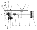
- the high-pressure shaft 1 is connected via a first switchable clutch 2, a high-pressure shaft gear 3 and a radial shaft 4 with an accessory gear 5, to the various accessories or accessories 6, namely a generator for generating and providing electrical energy for the aircraft and hydraulic pumps, oil pumps, fuel pumps and the like, are connected.
- a generator for generating and providing electrical energy for the aircraft and hydraulic pumps, oil pumps, fuel pumps and the like are connected.
- a sufficiently large amount of energy for the aircraft can thus be made available with a generator driven by the high-pressure shaft 1.
- the speed of the high pressure shaft 1 is insufficient to ensure a sufficiently large power extraction.
- An increase in the speed of the high-pressure shaft 1 would be associated with an unnecessarily high power consumption.
- the low-pressure shaft 7 is connected to the high-pressure shaft gear 3 via a low-pressure shaft gear 8 and a second switchable clutch 9 engaged in this phase and a belt pulley 10 and an overrunning clutch 11 so as to supply the energy of the high-pressure shaft in a low-speed phase Low-pressure wave 7 to the high-pressure shaft 1 to transmit and for the energy extraction on the generator and for the drive other accessories.
- the low-pressure shaft gear 8 serves to increase the speed to an amount at which maximum energy extraction is possible within the operating limits of the conical-pulley belt drive 10.
- the difference between the rotational speeds of the high-pressure shaft 1 and the low-pressure shaft 7 is compensated for by adjusting the conical-pulley 10 on the basis of a torque sensor 12 connected downstream thereof and a high-pressure and low-pressure shaft speed input signal.
- the conical-pulley belt drive 10 is a continuously variable transmission, consisting of two pairs of conical pulleys 14, 15 connected via a flexible belt 13 (power transmission means), each with conical disks arranged at a variable spacing.
- the two cone pulley pairs 14, 15 are each assigned an actuator 16, 17 operated by a pressure medium.
- the contact pressure on the belt 13 is increased or decreased by adjusting the distance between the conical disks of the respective conical pulley pair 14, 15 with the aid of the actuating member 16, 17 which controls and limits the transmission due to the torque signal.
- the high-pressure shaft gear 3 is used to adjust the output speed of the conical-pulley 10 to the speed of the high-pressure shaft 1 and to transfer energy to the accessory gear 5 via the radial shaft 4.
- the control of the actuators 14, 15 of the conical-pulley 10 via an engine control unit connected to the torque sensor 12 (not shown), which regulates the hydraulic pressure to the hydraulically operated actuators 14, 15.
- the one-way clutch 11 arranged between the conical-pulley belt transmission 10 and the high-pressure shaft transmission 3 ensures that energy is transmitted only from the low-pressure shaft to the high-pressure shaft and not vice versa. If the second shiftable clutch 9 is not engaged during certain phases of flight, the overrunning clutch 11 prevents the conical-pulley transmission 10 from being driven and thus the wear on the components of the conical-pulley belt transmission can be reduced.
- the above-mentioned first shiftable clutch connects the high-pressure shaft 1 to the high-pressure shaft gearbox 3.
- the high-pressure shaft 1 is separated from the high-pressure shaft gear 3 by this clutch 2, so that the fan (not shown) connected low pressure wave 7 can be driven independently of the high pressure shaft 1 and thus at a higher speed and the air resistance is reduced at the aircraft.
- the power generated by windmilling in engine failure of the low pressure shaft 7 via the decoupled from the high-pressure shaft 1 high-pressure shaft transmission 3 is transferred to the accessory gear 5 controlled in speed by the conical-pulley 10, so that electric and hydraulic power can be further generated to the devices 6 connected to the accessory gear 5.
Landscapes
- Engineering & Computer Science (AREA)
- Chemical & Material Sciences (AREA)
- Combustion & Propulsion (AREA)
- Mechanical Engineering (AREA)
- General Engineering & Computer Science (AREA)
- Connection Of Motors, Electrical Generators, Mechanical Devices, And The Like (AREA)
- Pulleys (AREA)
- Control Of Eletrric Generators (AREA)
- Control Of Transmission Device (AREA)
- Devices For Conveying Motion By Means Of Endless Flexible Members (AREA)
Applications Claiming Priority (1)
| Application Number | Priority Date | Filing Date | Title |
|---|---|---|---|
| DE102006039608A DE102006039608A1 (de) | 2006-08-24 | 2006-08-24 | Anordnung zur Energieentnahme bei einem Zwei-Wellen-Triebwerk |
Publications (3)
| Publication Number | Publication Date |
|---|---|
| EP1898073A2 true EP1898073A2 (fr) | 2008-03-12 |
| EP1898073A3 EP1898073A3 (fr) | 2010-03-24 |
| EP1898073B1 EP1898073B1 (fr) | 2013-05-08 |
Family
ID=38969478
Family Applications (1)
| Application Number | Title | Priority Date | Filing Date |
|---|---|---|---|
| EP07112560.3A Ceased EP1898073B1 (fr) | 2006-08-24 | 2007-07-16 | Dispositif de prise de puissance dans un turboréacteur double corps. |
Country Status (3)
| Country | Link |
|---|---|
| US (1) | US7833126B2 (fr) |
| EP (1) | EP1898073B1 (fr) |
| DE (1) | DE102006039608A1 (fr) |
Cited By (3)
| Publication number | Priority date | Publication date | Assignee | Title |
|---|---|---|---|---|
| WO2011007078A1 (fr) * | 2009-07-17 | 2011-01-20 | Snecma | Procédé et système pour la commande d'un démarreur-générateur de moteur d'aéronef |
| EP1933017A3 (fr) * | 2006-12-06 | 2011-08-31 | General Electric Company | Couplage variable de bobines de moteur de réacteur à double flux via un train d'engrenages planétaire ou différentiel ouvert avec couplage pour l'extraction de puissance et l'exploitabilité du moteur |
| CZ306718B6 (cs) * | 2014-05-21 | 2017-05-24 | Deprag Cz A.S. | Pohon pneumatického nářadí |
Families Citing this family (32)
| Publication number | Priority date | Publication date | Assignee | Title |
|---|---|---|---|---|
| FR2937088B1 (fr) * | 2008-10-13 | 2013-07-12 | Snecma | Distribution de fluide dans une turbomachine |
| DE102008062088B4 (de) * | 2008-12-12 | 2015-03-05 | Norbert Bayer | Vorrichtung zur Energie-Rückgewinnung in Flugzeugtriebwerken beim Landeanflug. |
| JP4923079B2 (ja) | 2009-03-27 | 2012-04-25 | ジヤトコ株式会社 | 無段変速機及びその制御方法 |
| JP4923080B2 (ja) * | 2009-03-27 | 2012-04-25 | ジヤトコ株式会社 | 無段変速機及びその制御方法 |
| JP5027179B2 (ja) * | 2009-03-27 | 2012-09-19 | ジヤトコ株式会社 | 無段変速機及びその制御方法 |
| JP4779030B2 (ja) * | 2009-03-27 | 2011-09-21 | ジヤトコ株式会社 | 無段変速機及びその制御方法 |
| JP4914467B2 (ja) | 2009-07-17 | 2012-04-11 | ジヤトコ株式会社 | 無段変速機及びその制御方法 |
| US8424416B2 (en) * | 2010-06-18 | 2013-04-23 | Hamilton Sundstrand Corporation | Layshaft generator |
| US8723385B2 (en) | 2011-10-07 | 2014-05-13 | General Electric Company | Generator |
| US8723349B2 (en) | 2011-10-07 | 2014-05-13 | General Electric Company | Apparatus for generating power from a turbine engine |
| US8966875B2 (en) * | 2011-10-21 | 2015-03-03 | United Technologies Corporation | Constant speed transmission for gas turbine engine |
| US8966876B2 (en) * | 2011-10-21 | 2015-03-03 | United Technologies Corporation | Controllable speed windmill operation of a gas turbine engine through low spool power extraction |
| US8978352B2 (en) * | 2011-10-21 | 2015-03-17 | United Technologies Corporation | Apparatus and method for operating a gas turbine engine during windmilling |
| US8978351B2 (en) * | 2011-10-21 | 2015-03-17 | United Technologies Corporation | Integrated thermal management system and environmental control system for a gas turbine engine |
| US20130232941A1 (en) * | 2012-03-07 | 2013-09-12 | Ge Aviation Systems Llc | Apparatus for extracting input power from the low pressure spool of a turbine engine |
| WO2013155264A1 (fr) * | 2012-04-11 | 2013-10-17 | Kirk Jones | Ensemble de prise de force multiunités empilable destiné à un véhicule tout-terrain |
| US20140090388A1 (en) * | 2012-09-28 | 2014-04-03 | United Technologies Corporation | Off-take power ratio |
| US8726629B2 (en) * | 2012-10-04 | 2014-05-20 | Lightsail Energy, Inc. | Compressed air energy system integrated with gas turbine |
| GB201219544D0 (en) * | 2012-10-31 | 2012-12-12 | Rolls Royce Deutschland | Geared compressor for gas turbine engine |
| US8851043B1 (en) | 2013-03-15 | 2014-10-07 | Lightsail Energy, Inc. | Energy recovery from compressed gas |
| US8702373B1 (en) * | 2013-07-15 | 2014-04-22 | United Technologies Corporation | Lubrication of journal bearing during clockwise and counter-clockwise rotation |
| DE102014201958A1 (de) * | 2014-02-04 | 2015-08-06 | Zf Friedrichshafen Ag | Schwingungsdämpfer mit einem Generatoranschluss |
| DE102014201960B4 (de) * | 2014-02-04 | 2025-01-02 | Zf Friedrichshafen Ag | Schwingungsdämpfer mit einem Generatoranschluss |
| US9580129B2 (en) | 2015-05-13 | 2017-02-28 | Burromax LLC | Assembly comprising an internal combustion engine selectively couple to generator and to another mechanically driven device |
| US12276230B2 (en) * | 2019-03-20 | 2025-04-15 | Rtx Corporation | Variable transmission driven fuel pump for a gas turbine engine |
| US11834998B2 (en) * | 2019-04-18 | 2023-12-05 | Hamilton Sundstrand Corporation | Transmission systems having clutch at output side |
| US12447685B2 (en) | 2020-07-23 | 2025-10-21 | General Electric Company | System and method of additively manufacturing a component with multiple processing strategies |
| US11591967B2 (en) * | 2020-12-21 | 2023-02-28 | The Boeing Company | Systems and methods for providing mechanical power to an aircraft accessory with a turbine engine |
| FR3142223A1 (fr) * | 2022-11-22 | 2024-05-24 | Safran Aircraft Engines | Turbomachine d’aeronef comportant un circuit de carburant optimise |
| US20260043355A1 (en) * | 2024-08-06 | 2026-02-12 | The Boeing Company | System to Selectively Transfer Power of a Turbine Engine |
| US20260063076A1 (en) * | 2024-09-03 | 2026-03-05 | General Electric Company | Gas turbine engine having a mechanical power sharing arrangement |
| CN119803944B (zh) * | 2025-03-13 | 2025-05-16 | 中国航发沈阳发动机研究所 | 一种同侧输入的双轴压气机试验器及其起动方法 |
Family Cites Families (9)
| Publication number | Priority date | Publication date | Assignee | Title |
|---|---|---|---|---|
| US3514945A (en) * | 1968-10-04 | 1970-06-02 | Avco Corp | Gas turbine accessory power drive unit |
| US4064690A (en) * | 1974-05-17 | 1977-12-27 | United Turbine Ab & Co. | Gas turbine power plant |
| SE402147B (sv) * | 1975-12-05 | 1978-06-19 | United Turbine Ab & Co | Gasturbinanleggning med tre i samma gaspassage anordnade koaxiella turbinrotorer |
| SE401711B (sv) * | 1976-09-24 | 1978-05-22 | Kronogard Sven Olof | Gasturbin-transmissionsanleggning |
| DE3602543A1 (de) * | 1986-01-29 | 1987-10-01 | Walter Schopf | Abgasturbolader mit dynamischen ladeverhalten |
| DE3622022A1 (de) * | 1986-07-01 | 1988-01-07 | Kloeckner Humboldt Deutz Ag | Gasturbinentriebwerk |
| FR2826052B1 (fr) * | 2001-06-19 | 2003-12-19 | Snecma Moteurs | Dispositif de secours au rallumage d'un turboreacteur en autorotation |
| JP3954928B2 (ja) * | 2002-08-20 | 2007-08-08 | 本田技研工業株式会社 | 車両の動力伝達装置 |
| FR2863312B1 (fr) * | 2003-12-09 | 2008-07-04 | Snecma Moteurs | Turboreacteur a double corps avec moyen d'entrainement des machines accessoires |
-
2006
- 2006-08-24 DE DE102006039608A patent/DE102006039608A1/de not_active Withdrawn
-
2007
- 2007-07-16 EP EP07112560.3A patent/EP1898073B1/fr not_active Ceased
- 2007-08-22 US US11/892,325 patent/US7833126B2/en not_active Expired - Fee Related
Non-Patent Citations (1)
| Title |
|---|
| None |
Cited By (7)
| Publication number | Priority date | Publication date | Assignee | Title |
|---|---|---|---|---|
| EP1933017A3 (fr) * | 2006-12-06 | 2011-08-31 | General Electric Company | Couplage variable de bobines de moteur de réacteur à double flux via un train d'engrenages planétaire ou différentiel ouvert avec couplage pour l'extraction de puissance et l'exploitabilité du moteur |
| WO2011007078A1 (fr) * | 2009-07-17 | 2011-01-20 | Snecma | Procédé et système pour la commande d'un démarreur-générateur de moteur d'aéronef |
| FR2948151A1 (fr) * | 2009-07-17 | 2011-01-21 | Snecma | Procede et systeme pour la commande d'un demarreur-generateur de moteur d'aeronef |
| GB2484230A (en) * | 2009-07-17 | 2012-04-04 | Snecma | Method and system for controlling aircraft engine starter/generator |
| US8979705B2 (en) | 2009-07-17 | 2015-03-17 | Snecma | Method and system for controlling aircraft engine starter/generator |
| GB2484230B (en) * | 2009-07-17 | 2016-03-30 | Snecma | Method and system for controlling aircraft engine starter/generator |
| CZ306718B6 (cs) * | 2014-05-21 | 2017-05-24 | Deprag Cz A.S. | Pohon pneumatického nářadí |
Also Published As
| Publication number | Publication date |
|---|---|
| US7833126B2 (en) | 2010-11-16 |
| EP1898073B1 (fr) | 2013-05-08 |
| US20080047376A1 (en) | 2008-02-28 |
| DE102006039608A1 (de) | 2008-04-10 |
| EP1898073A3 (fr) | 2010-03-24 |
Similar Documents
| Publication | Publication Date | Title |
|---|---|---|
| EP1898073B1 (fr) | Dispositif de prise de puissance dans un turboréacteur double corps. | |
| DE69407555T2 (de) | Variable kraftübertragung zwischen den verschiedenen wellen einer mehrwellengasturbine | |
| WO2017220296A1 (fr) | Alimentation en lubrifiant pour une propulsion électrique et véhicule automobile comprenant une telle alimentation en lubrifiant | |
| EP3298685B1 (fr) | Système d'entraînement à vitesse de rotation variable et procédé de démarrage et/ou de fonctionnement d'un système d'entraînement à vitesse de rotation variable | |
| EP3080473B1 (fr) | Système hydraulique pour double embrayage ainsi que procédé de commande ou de refroidissement du double embrayage | |
| DE112013003307T5 (de) | Fahrzeughydrauliksteuervorrichtung | |
| DE2044441B2 (de) | Aus einem hydrostatisch-mechanischen ueberlagerungsgetriebe mit leistungsverzweigung und einem generator bestehende antriebseinheit | |
| DE10355917A1 (de) | Gasturbine, insbesondere Flugtriebwerk, und Verfahren zur Erzeugung elektrischer Energie bei einer Gasturbine | |
| WO2019091719A1 (fr) | Transmission pour véhicule automobile | |
| WO2011124322A2 (fr) | Branche de centrale comprenant une pompe variable en régime | |
| DE102016217541A1 (de) | Hydraulisches Antriebssystem mit mehreren Zulaufleitungen | |
| DE102022100573B3 (de) | Hydrauliksystem mit Hoch- und Trockensumpf | |
| DE102018214427A1 (de) | Hydrauliksystem für ein Doppelkupplungsgetriebe | |
| EP1565676B2 (fr) | Systeme d'entrainement multimoteur hydrostatique | |
| DE102008035142A1 (de) | Hydraulikanordnung für ein Automatikgetriebe | |
| EP3289191B1 (fr) | Dispositif de propulsion des auxiliaires | |
| DE102011078854A1 (de) | Ölversorgungseinrichtung eines Schaltgetriebes und Verfahren zur Ölversorgung | |
| DE102010060972A1 (de) | Anordnung zum Antrieb eines Sauggebläses in einem Saugbagger | |
| DE102016200644B4 (de) | Kompaktes Mehrstufengetriebe | |
| EP2143912A1 (fr) | Turbine à gaz dotée d'au moins une unité de compresseur à plusieurs étages comprenant plusieurs modules de compresseur | |
| EP2108799B1 (fr) | Moteur à réaction doté d'au moins un entraînement de secours | |
| EP1029814A1 (fr) | Unité d'entraínement pour systèmes de convoyeurs avec commande ou reglage du démarrage | |
| DE102012110762A1 (de) | Anordnung zum Versorgen von Getriebeelementen mit Schmieröl | |
| DE10357608B4 (de) | Nebenaggregatezug eines Kfz-Verbrennungsmotors und Verfahren zur Steuerung eines Nebenaggregatezuges | |
| DE102005032226A1 (de) | Schmiermittelversorgungssystem eines Kraftfahrzeugs |
Legal Events
| Date | Code | Title | Description |
|---|---|---|---|
| PUAI | Public reference made under article 153(3) epc to a published international application that has entered the european phase |
Free format text: ORIGINAL CODE: 0009012 |
|
| AK | Designated contracting states |
Kind code of ref document: A2 Designated state(s): AT BE BG CH CY CZ DE DK EE ES FI FR GB GR HU IE IS IT LI LT LU LV MC MT NL PL PT RO SE SI SK TR |
|
| AX | Request for extension of the european patent |
Extension state: AL BA HR MK YU |
|
| RIN1 | Information on inventor provided before grant (corrected) |
Inventor name: VENTER, GIDEON DANIEL |
|
| PUAL | Search report despatched |
Free format text: ORIGINAL CODE: 0009013 |
|
| AK | Designated contracting states |
Kind code of ref document: A3 Designated state(s): AT BE BG CH CY CZ DE DK EE ES FI FR GB GR HU IE IS IT LI LT LU LV MC MT NL PL PT RO SE SI SK TR |
|
| AX | Request for extension of the european patent |
Extension state: AL BA HR MK RS |
|
| RIC1 | Information provided on ipc code assigned before grant |
Ipc: F02C 7/32 20060101ALI20100212BHEP Ipc: F02C 7/36 20060101AFI20080201BHEP Ipc: F02C 3/107 20060101ALI20100212BHEP Ipc: F02C 3/113 20060101ALI20100212BHEP |
|
| 17P | Request for examination filed |
Effective date: 20100924 |
|
| AKX | Designation fees paid |
Designated state(s): DE FR GB |
|
| RTI1 | Title (correction) |
Free format text: ASSEMBLY FOR POWER TAKE-OFF IN A TWO-SPOOL TURBINE ENGINE. |
|
| GRAP | Despatch of communication of intention to grant a patent |
Free format text: ORIGINAL CODE: EPIDOSNIGR1 |
|
| GRAJ | Information related to disapproval of communication of intention to grant by the applicant or resumption of examination proceedings by the epo deleted |
Free format text: ORIGINAL CODE: EPIDOSDIGR1 |
|
| GRAP | Despatch of communication of intention to grant a patent |
Free format text: ORIGINAL CODE: EPIDOSNIGR1 |
|
| GRAS | Grant fee paid |
Free format text: ORIGINAL CODE: EPIDOSNIGR3 |
|
| GRAA | (expected) grant |
Free format text: ORIGINAL CODE: 0009210 |
|
| RAP1 | Party data changed (applicant data changed or rights of an application transferred) |
Owner name: ROLLS-ROYCE DEUTSCHLAND LTD & CO KG |
|
| AK | Designated contracting states |
Kind code of ref document: B1 Designated state(s): DE FR GB |
|
| REG | Reference to a national code |
Ref country code: GB Ref legal event code: FG4D Free format text: NOT ENGLISH |
|
| REG | Reference to a national code |
Ref country code: DE Ref legal event code: R096 Ref document number: 502007011724 Country of ref document: DE Effective date: 20130704 |
|
| PLBE | No opposition filed within time limit |
Free format text: ORIGINAL CODE: 0009261 |
|
| STAA | Information on the status of an ep patent application or granted ep patent |
Free format text: STATUS: NO OPPOSITION FILED WITHIN TIME LIMIT |
|
| 26N | No opposition filed |
Effective date: 20140211 |
|
| REG | Reference to a national code |
Ref country code: DE Ref legal event code: R097 Ref document number: 502007011724 Country of ref document: DE Effective date: 20140211 |
|
| REG | Reference to a national code |
Ref country code: FR Ref legal event code: PLFP Year of fee payment: 10 |
|
| REG | Reference to a national code |
Ref country code: FR Ref legal event code: PLFP Year of fee payment: 11 |
|
| REG | Reference to a national code |
Ref country code: FR Ref legal event code: PLFP Year of fee payment: 12 |
|
| PGFP | Annual fee paid to national office [announced via postgrant information from national office to epo] |
Ref country code: DE Payment date: 20190729 Year of fee payment: 13 Ref country code: FR Payment date: 20190725 Year of fee payment: 13 |
|
| PGFP | Annual fee paid to national office [announced via postgrant information from national office to epo] |
Ref country code: GB Payment date: 20190729 Year of fee payment: 13 |
|
| REG | Reference to a national code |
Ref country code: DE Ref legal event code: R082 Ref document number: 502007011724 Country of ref document: DE |
|
| REG | Reference to a national code |
Ref country code: DE Ref legal event code: R119 Ref document number: 502007011724 Country of ref document: DE |
|
| GBPC | Gb: european patent ceased through non-payment of renewal fee |
Effective date: 20200716 |
|
| PG25 | Lapsed in a contracting state [announced via postgrant information from national office to epo] |
Ref country code: FR Free format text: LAPSE BECAUSE OF NON-PAYMENT OF DUE FEES Effective date: 20200731 Ref country code: GB Free format text: LAPSE BECAUSE OF NON-PAYMENT OF DUE FEES Effective date: 20200716 |
|
| PG25 | Lapsed in a contracting state [announced via postgrant information from national office to epo] |
Ref country code: DE Free format text: LAPSE BECAUSE OF NON-PAYMENT OF DUE FEES Effective date: 20210202 |