EP1898197A2 - Upgraded balancing machine for vehicle wheels - Google Patents
Upgraded balancing machine for vehicle wheels Download PDFInfo
- Publication number
- EP1898197A2 EP1898197A2 EP07015170A EP07015170A EP1898197A2 EP 1898197 A2 EP1898197 A2 EP 1898197A2 EP 07015170 A EP07015170 A EP 07015170A EP 07015170 A EP07015170 A EP 07015170A EP 1898197 A2 EP1898197 A2 EP 1898197A2
- Authority
- EP
- European Patent Office
- Prior art keywords
- machine according
- sensor
- wheel
- detection
- means comprise
- Prior art date
- Legal status (The legal status is an assumption and is not a legal conclusion. Google has not performed a legal analysis and makes no representation as to the accuracy of the status listed.)
- Ceased
Links
Images

Classifications
-
- G—PHYSICS
- G01—MEASURING; TESTING
- G01M—TESTING STATIC OR DYNAMIC BALANCE OF MACHINES OR STRUCTURES; TESTING OF STRUCTURES OR APPARATUS, NOT OTHERWISE PROVIDED FOR
- G01M1/00—Testing static or dynamic balance of machines or structures
- G01M1/14—Determining imbalance
- G01M1/16—Determining imbalance by oscillating or rotating the body to be tested
- G01M1/22—Determining imbalance by oscillating or rotating the body to be tested and converting vibrations due to imbalance into electric variables
- G01M1/225—Determining imbalance by oscillating or rotating the body to be tested and converting vibrations due to imbalance into electric variables for vehicle wheels
-
- G—PHYSICS
- G01—MEASURING; TESTING
- G01M—TESTING STATIC OR DYNAMIC BALANCE OF MACHINES OR STRUCTURES; TESTING OF STRUCTURES OR APPARATUS, NOT OTHERWISE PROVIDED FOR
- G01M1/00—Testing static or dynamic balance of machines or structures
- G01M1/02—Details of balancing machines or devices
Definitions
- the present invention refers to an upgraded balancing machine for vehicle wheels.
- vehicle wheels are generally made up of a cylindrical metal rim having, at the axial ends, ring-shaped flanges between which is defined a channel for the interlock of an elastic tyre, the side portions of which, the so-called “beads”, are positioned fast up to the ring-shaped flanges.
- the need is also known to perform frequent balancing operations that consist in applying weights, made of lead or other material, at predetermined points of the wheel and along the rim.
- the fitting of the weights offsets the presence of any tyre and/or rim irregularities.
- balancing machines are commonly used that comprise a supporting structure for wheel gripping and rotation means, of the type of a horizontal shaft that can turn axially by means of motor means and onto which the wheel rim is keyed.
- the measurement of the wheel unbalance is detected during rotation by suitable electronic or electromechanical devices, such as force transducers fitted along the horizontal shaft.
- Each of the detected measurements is normally related to a respective angular position of the wheel on the rotation axis detected by an angular position transducer (encoder) associated with the horizontal shaft.
- an angular position transducer encoder
- the unbalance and the other specific measurements made on the wheel are performed by sampling the signals coming from the respective measuring sensors at preset and constant angular intervals determined by the technical characteristics of the encoder.
- the frequency of samplings made by the measuring devices on the wheel is closely tied to predetermined angular positions and is restricted by the technical characteristics of the encoder.
- the angular resolution of the encoder generally suitable for measuring unbalance, can be insufficient and not allow sufficiently accurate measurements in case, for example, of measuring the roundness or the eccentricity of the wheel.
- the low resolution of the measurements made, together with the presence of numerous branched grooves that extend irregularly on the surface of the tread tends to falsify the testing of the tyre characteristics.
- the main aim of the present invention is to provide an upgraded balancing machine for vehicle wheels that permits upgrading the quality and the precision of the measurements taken without having to increase the angular resolution of the encoder.
- Another object of the present invention is to cater for the above aims with a simple structure, of relatively practical implementation, safe to use and with effective operation, as well as having a relatively low cost.
- the present upgraded balancing machine for vehicle wheels comprising a supporting frame for gripping and rotation means for gripping and rotating a wheel to be balanced around a rotation axis, first detection means for detecting the unbalance of said wheel with respect to said rotation axis suitable for generating a first analogue signal, second detection means for detecting at least one portion of the profile of said wheel suitable for generating a second analogue signal, at least one conversion device associated with at least one between said first and said second detection means and suitable for converting at least one between said first and said second analogue signal into a corresponding digital signal, a processing and control unit associated with said conversion device and suitable for processing said digital signal, characterized in that it comprises adjustment means which are suitable for adjusting the sampling frequency of at least one between said first and said second analogue signal and which are associated with said conversion device.
- the machine 1 comprises a frame 2 that supports gripping and rotation means 3 for gripping and rotating a wheel R to be balanced around a substantially horizontal rotation axis A.
- the frame 2 is made up of a base block 2a, containing the support and motorisation system of the gripping and rotation means 3, and of a vertical wall 2b associated with a side of the base block 2a.
- the gripping and rotation means 3 comprise a shaft 4 defining the rotation axis A which extends horizontally and overhanging from the base block 2a.
- the free end of the shaft 4 has a bush suitable for fixing and centring the rim of the wheel R.
- the machine 1 comprises first detection means 5 of the unbalance of the wheel R with respect to the rotation axis A.
- the first detection means 5 can comprise a pair of force transducers, of the load cell type or the like, associated together spaced along a section of the shaft 4 and suitable for detecting variations in the forces exercised by the wheel R along the shaft 4 during rotation.
- the machine 1 also comprises second detection means 6 of at least a portion of the profile of the wheel R.
- the second detection means 6, in the particular embodiment of the invention illustrated in figure 1, comprise a first sensor 7 of the type without contact, such as an optical sensor or a distance laser sensor, which is fitted sliding on straight guiding means 8.
- a first sensor 7 of the type without contact such as an optical sensor or a distance laser sensor, which is fitted sliding on straight guiding means 8.
- the straight guiding means 8 extend in a direction parallel to that of the rotation axis A and are made up, for example, of two supporting bars fastened to the upper portion of the vertical wall 2b.
- the sliding of the first sensor 7 along the supporting bars is obtained by means of movement means made up, usefully, of a flexible body, of the belt type or the like, which is closed on itself like a ring, is associated with the first sensor 7 and is wrapped on two rotating disks, one of which is the drive disk and the other the driven disk.
- the second detection means 6 can comprise a second detection sensor for detecting a portion of the side surface of the wheel R.
- the machine 1 can envisage a pair of second sensors of the type with or without contact such as feelers, optical sensors or distance laser sensors, associated moving or fixed to the frame 2 and arranged facing the two side surfaces opposite the wheel R.
- second sensors of the type with or without contact such as feelers, optical sensors or distance laser sensors, associated moving or fixed to the frame 2 and arranged facing the two side surfaces opposite the wheel R.
- first and second different detection means 5 and 6 with different number and arrangement of the force transducers, of the first sensor 7 and of the second sensors.
- the force transducers of the first detection means 5 generate, during the rotation of the wheel R, a first analogue output signal S A1 , modulated according to the changes in force detected along the shaft 4.
- the first sensor 7 (and possibly the second sensors) of the second detection means 6 generates, during the rotation of the wheel R, a second analogue output signal S A2 , modulated according to the particular shape and position of the surface along the circumference of the tyre, at the tread.
- the first and the second detection means 5 and 6 are associated with a conversion device 9, of the analogue-digital converter type, which receives the first and/or the second analogue signal S A1 and S A2 and converts these into respective digital signals S D .
- the machine 1 comprises adjustment means 10 associated with the conversion device 9 and suitable for piloting the sampling frequency of the first and second analogue signal S A1 and S A2 .
- the adjustment means 10 are made up of a determination device for determining the above sampling frequency starting with the frequency generated by a programmable timer 13, if necessary synchronised with a reference signal S R .
- the reference signal S R can be of the type of an impulsive electrical signal produced by first generation means 11, during the rotation of the wheel R and at just one predetermined angular position.
- the first generation means 11 are made up of a first detection device of the type, for example, of an optical sensor suitable for detecting a determined area of reference on the surface of the tyre or of the rim of the wheel R.
- the first detection device 11 can be made up of an encoder which is associated with the shaft 4 and which measures the rotation around its own axis for determining just one or more angular positions of the wheel R and for the generation of corresponding reference signals S R .
- the reference signal S R so determined is then sent to the determination device 10 which, by means of the programmable timer 13, generates a piloting signal S P of the conversion device 9 the sampling frequency of which is a multiple of the frequency of the reference signal S R or, in any case, the sampling frequency of which is substantially greater and synchronous with respect to the frequency of the reference signal S R .
- a management and control unit 12 is associated with the determination device 10 for selecting the multiplication factor M of the input reference signal S R and, therefore, for changing the frequency of the output piloting signal S P .
- the timer 13 can be suitably programmed according to the angular speed of the wheel R. In this case, therefore, there is no need to synchronise the piloting signal S P with respect to the reference signal S R and, consequently, the measurement of just one or more angular positions of the wheel R is superfluous.
- the management and control unit 12 is suitable for controlling the determination device 10 for the dynamic adjustment of the sampling frequency during a same measuring cycle.
- the frequency of the piloting signal S P is increased in case of a higher speed of change in the first and/or the second analogue signal S A1 and S A2 or, on the contrary, the frequency of the piloting signal S P is reduced in case of a reduction in the speed of change of the first and/or the second analogue signal S A1 and S A2 .
- the machine 1 can also comprise second generation means for generating the reference signal S R in relation to the movement of the first sensor 7 along the straight guiding means 8 and at predefined axial positions of the first sensor 7 itself.
- the second generation means can comprise a second sensor device, of the type of an encoder, suitable for detecting one or more angular positions of at least one between the rotating disks for the movement of the first sensor 7.
- the digital signal S D resulting from the sampling of the first analogue signal S A1 and/or of the second analogue signal S A2 is sent to the management and control unit 12, which is of the type of a microprocessor system, and is processed for testing unbalance, roundness, eccentricity, tread wear, etc., on the wheel R.
- the data thus processed can be sent to display means 14, of the type of a monitor or the like, for analysing the results on the part of an operator.
- the presence of the programmable timer permits the execution of particular measurements on the tyre, such as taper or roundness, quite apart from the measurement of just one or more angular positions of the wheel.
Landscapes
- Physics & Mathematics (AREA)
- General Physics & Mathematics (AREA)
- Testing Of Balance (AREA)
Abstract
Description
- The present invention refers to an upgraded balancing machine for vehicle wheels.
- It is known that vehicle wheels are generally made up of a cylindrical metal rim having, at the axial ends, ring-shaped flanges between which is defined a channel for the interlock of an elastic tyre, the side portions of which, the so-called "beads", are positioned fast up to the ring-shaped flanges.
- The need is also known to perform frequent balancing operations that consist in applying weights, made of lead or other material, at predetermined points of the wheel and along the rim.
- During wheel turning, the fitting of the weights offsets the presence of any tyre and/or rim irregularities.
- To perform such operations, balancing machines are commonly used that comprise a supporting structure for wheel gripping and rotation means, of the type of a horizontal shaft that can turn axially by means of motor means and onto which the wheel rim is keyed.
- The measurement of the wheel unbalance is detected during rotation by suitable electronic or electromechanical devices, such as force transducers fitted along the horizontal shaft.
- To the unbalance measurement, other characteristic measurements are generally added such as the measurement of the wheel roundness, the eccentricity of the wheel, the amount of tread wear, etc., normally performed by means of suitable measuring sensors with or without contact (for example feeler pins or optical sensors).
- Each of the detected measurements is normally related to a respective angular position of the wheel on the rotation axis detected by an angular position transducer (encoder) associated with the horizontal shaft.
- In particular, the unbalance and the other specific measurements made on the wheel are performed by sampling the signals coming from the respective measuring sensors at preset and constant angular intervals determined by the technical characteristics of the encoder.
- These known balancing machines are however susceptible to upgrading, in particular in order to upgrade the quality and the precision of the measurements taken.
- In fact, the frequency of samplings made by the measuring devices on the wheel is closely tied to predetermined angular positions and is restricted by the technical characteristics of the encoder. In particular, the angular resolution of the encoder, generally suitable for measuring unbalance, can be insufficient and not allow sufficiently accurate measurements in case, for example, of measuring the roundness or the eccentricity of the wheel. In fact, the low resolution of the measurements made, together with the presence of numerous branched grooves that extend irregularly on the surface of the tread, tends to falsify the testing of the tyre characteristics.
- The main aim of the present invention is to provide an upgraded balancing machine for vehicle wheels that permits upgrading the quality and the precision of the measurements taken without having to increase the angular resolution of the encoder.
- Within the scope of this technical aim, another object of the present invention is to cater for the above aims with a simple structure, of relatively practical implementation, safe to use and with effective operation, as well as having a relatively low cost.
- The objects indicated above are all achieved by the present upgraded balancing machine for vehicle wheels, comprising a supporting frame for gripping and rotation means for gripping and rotating a wheel to be balanced around a rotation axis, first detection means for detecting the unbalance of said wheel with respect to said rotation axis suitable for generating a first analogue signal, second detection means for detecting at least one portion of the profile of said wheel suitable for generating a second analogue signal, at least one conversion device associated with at least one between said first and said second detection means and suitable for converting at least one between said first and said second analogue signal into a corresponding digital signal, a processing and control unit associated with said conversion device and suitable for processing said digital signal, characterized in that it comprises adjustment means which are suitable for adjusting the sampling frequency of at least one between said first and said second analogue signal and which are associated with said conversion device.
- Further characteristics and advantages of the present invention will appear even more evident from the detailed description of a preferred, but not exclusive, embodiment of an upgraded balancing machine for vehicle wheels illustrated indicatively by way of non limiting example, in the attached drawings wherein:
- the figure 1 is a perspective view of the machine according to the invention;
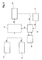
- the figure 2 is an operating diagram of the machine according to the invention.
- With special reference to such figures, an upgraded balancing machine for vehicle wheels has been globally designated by reference number 1.
- The machine 1 comprises a
frame 2 that supports gripping and rotation means 3 for gripping and rotating a wheel R to be balanced around a substantially horizontal rotation axis A. - Particularly, the
frame 2 is made up of abase block 2a, containing the support and motorisation system of the gripping and rotation means 3, and of avertical wall 2b associated with a side of thebase block 2a. - The gripping and rotation means 3 comprise a
shaft 4 defining the rotation axis A which extends horizontally and overhanging from thebase block 2a. The free end of theshaft 4 has a bush suitable for fixing and centring the rim of the wheel R. - The machine 1 comprises first detection means 5 of the unbalance of the wheel R with respect to the rotation axis A.
- In particular, the first detection means 5 can comprise a pair of force transducers, of the load cell type or the like, associated together spaced along a section of the
shaft 4 and suitable for detecting variations in the forces exercised by the wheel R along theshaft 4 during rotation. - The machine 1 also comprises second detection means 6 of at least a portion of the profile of the wheel R.
- The second detection means 6, in the particular embodiment of the invention illustrated in figure 1, comprise a
first sensor 7 of the type without contact, such as an optical sensor or a distance laser sensor, which is fitted sliding on straight guidingmeans 8. - The straight guiding means 8 extend in a direction parallel to that of the rotation axis A and are made up, for example, of two supporting bars fastened to the upper portion of the
vertical wall 2b. The sliding of thefirst sensor 7 along the supporting bars is obtained by means of movement means made up, usefully, of a flexible body, of the belt type or the like, which is closed on itself like a ring, is associated with thefirst sensor 7 and is wrapped on two rotating disks, one of which is the drive disk and the other the driven disk. - Advantageously, the second detection means 6 can comprise a second detection sensor for detecting a portion of the side surface of the wheel R.
- In particular, the machine 1 can envisage a pair of second sensors of the type with or without contact such as feelers, optical sensors or distance laser sensors, associated moving or fixed to the
frame 2 and arranged facing the two side surfaces opposite the wheel R. - The presence cannot however be ruled out of first and second different detection means 5 and 6, with different number and arrangement of the force transducers, of the
first sensor 7 and of the second sensors. - Advantageously, the force transducers of the first detection means 5 generate, during the rotation of the wheel R, a first analogue output signal SA1, modulated according to the changes in force detected along the
shaft 4. - In the same way, the first sensor 7 (and possibly the second sensors) of the second detection means 6 generates, during the rotation of the wheel R, a second analogue output signal SA2, modulated according to the particular shape and position of the surface along the circumference of the tyre, at the tread.
- As the diagram of figure 2 shows, the first and the second detection means 5 and 6 are associated with a
conversion device 9, of the analogue-digital converter type, which receives the first and/or the second analogue signal SA1 and SA2 and converts these into respective digital signals SD. - Advantageously, the machine 1 comprises adjustment means 10 associated with the
conversion device 9 and suitable for piloting the sampling frequency of the first and second analogue signal SA1 and SA2. - In particular, the adjustment means 10 are made up of a determination device for determining the above sampling frequency starting with the frequency generated by a
programmable timer 13, if necessary synchronised with a reference signal SR. - Usefully, the reference signal SR can be of the type of an impulsive electrical signal produced by first generation means 11, during the rotation of the wheel R and at just one predetermined angular position.
- The first generation means 11 are made up of a first detection device of the type, for example, of an optical sensor suitable for detecting a determined area of reference on the surface of the tyre or of the rim of the wheel R.
- Alternatively, the
first detection device 11 can be made up of an encoder which is associated with theshaft 4 and which measures the rotation around its own axis for determining just one or more angular positions of the wheel R and for the generation of corresponding reference signals SR. - The reference signal SR so determined is then sent to the
determination device 10 which, by means of theprogrammable timer 13, generates a piloting signal SP of theconversion device 9 the sampling frequency of which is a multiple of the frequency of the reference signal SR or, in any case, the sampling frequency of which is substantially greater and synchronous with respect to the frequency of the reference signal SR. - Usefully, a management and
control unit 12 is associated with thedetermination device 10 for selecting the multiplication factor M of the input reference signal SR and, therefore, for changing the frequency of the output piloting signal SP. - Advantageously, in specific measurement phases and in the event of the wheel R rotating at a preset angular speed, the
timer 13 can be suitably programmed according to the angular speed of the wheel R. In this case, therefore, there is no need to synchronise the piloting signal SP with respect to the reference signal SR and, consequently, the measurement of just one or more angular positions of the wheel R is superfluous. - Conveniently, the management and
control unit 12 is suitable for controlling thedetermination device 10 for the dynamic adjustment of the sampling frequency during a same measuring cycle. In particular, the frequency of the piloting signal SP is increased in case of a higher speed of change in the first and/or the second analogue signal SA1 and SA2 or, on the contrary, the frequency of the piloting signal SP is reduced in case of a reduction in the speed of change of the first and/or the second analogue signal SA1 and SA2. - The machine 1 can also comprise second generation means for generating the reference signal SR in relation to the movement of the
first sensor 7 along the straight guidingmeans 8 and at predefined axial positions of thefirst sensor 7 itself. - In particular, the second generation means can comprise a second sensor device, of the type of an encoder, suitable for detecting one or more angular positions of at least one between the rotating disks for the movement of the
first sensor 7. - The digital signal SD resulting from the sampling of the first analogue signal SA1 and/or of the second analogue signal SA2 is sent to the management and
control unit 12, which is of the type of a microprocessor system, and is processed for testing unbalance, roundness, eccentricity, tread wear, etc., on the wheel R. - The data thus processed can be sent to display means 14, of the type of a monitor or the like, for analysing the results on the part of an operator.
- It has in fact been found how the described invention achieves the proposed objects and in particular the fact is underlined that the presence of the adjustment means of the sampling frequency permits upgrading the quality and the precision of the measurements taken.
- In fact, the possibility of sampling the input analogue signals at frequencies higher than those commonly used permits a greater resolution of the digital signal obtained, ensuring a precise measurement even in the case of irregular surfaces such as those of the tyre tread.
- Furthermore, the presence of the programmable timer permits the execution of particular measurements on the tyre, such as taper or roundness, quite apart from the measurement of just one or more angular positions of the wheel.
- To this must be added the fact that, in case of the synchronisation of the sampling frequency with the frequency of the reference signal, a correct association is in any case ensured between the measurement taken and the corresponding angular position of the wheel.
- The invention thus conceived is susceptible of numerous modifications and variations, all of which falling within the scope of the inventive concept.
- Furthermore all the details may be replaced by other elements which are technically equivalent.
- In practice, the contingent shapes and dimensions may be any according to requirements without because of this moving outside the protection scope of the following claims.
Claims (24)
- Upgraded balancing machine for vehicle wheels, comprising a supporting frame for gripping and rotation means for gripping and rotating a wheel to be balanced around a rotation axis, first detection means for detecting the unbalance of said wheel with respect to said rotation axis suitable for generating a first analogue signal, second detection means for detecting at least one portion of the profile of said wheel suitable for generating a second analogue signal, at least one conversion device associated with at least one between said first and said second detection means and suitable for converting at least one between said first and said second analogue signal into a corresponding digital signal, a processing and control unit associated with said conversion device and suitable for processing said digital signal, characterized in that it comprises adjustment means which are suitable for adjusting the sampling frequency of at least one between said first and said second analogue signal and which are associated with said conversion device.
- Machine according to claim 1, characterized in that said adjustments means comprise at least one determination device for determining said sampling frequency starting with the frequency generated by a programmable timer.
- Machine according to one or more of the preceding claims, characterized in that said determination device is suitable for the synchronisation of said sampling frequency with respect to the frequency of at least one reference signal.
- Machine according to one or more of the preceding claims, characterized in that said determination device is suitable for the adjustment of said sampling frequency with respect to the speed of change of at least one between said first and said second analogue signal.
- Machine according to one or more of the preceding claims, characterized in that said determination device is associated with said processing and control unit.
- Machine according to one or more of the preceding claims, characterized in that it comprises first generation means of said reference signal during the rotation of said wheel and by at least one angular position of said wheel with respect to said rotation axis.
- Machine according to one or more of the preceding claims, characterized in that said first generation means comprise at least one first detection device of said angular position.
- Machine according to one or more of the preceding claims, characterized in that said first detection device is of the type of an optical sensor.
- Machine according to one or more of the preceding claims, characterized in that said first detection device is of the type of an encoder.
- Machine according to one or more of the preceding claims, characterized in that said reference signal is of the type of an impulsive electrical signal.
- Machine according to one or more of the preceding claims, characterized in that said first detection means comprise at least one force transducer operatively associated with said gripping and rotation means.
- Machine according to one or more of the preceding claims, characterized in that said second detection means comprise at least one first detection sensor of at least a portion of the tread profile of said wheel.
- Machine according to one or more of the preceding claims, characterized in that said second detection means comprise straight guiding means of said first sensor in a direction substantially parallel to said rotation axis.
- Machine according to one or more of the preceding claims, characterized in that said straight guiding means comprise at least two sliding supporting bars of said first sensor, associated with said frame and arranged parallel to said rotation axis.
- Machine according to one or more of the preceding claims, characterized in that said second detection means comprise movement means of said first sensor along said guiding means.
- Machine according to one or more of the preceding claims, characterized in that said movement means comprise at least one flexible body closed on itself like a ring, associated with said first sensor and wrapped on at least a pair of rotating disks, one of which is the drive disk.
- Machine according to one or more of the preceding claims, characterized in that it comprises second generation means of said reference signal during the movement of said first sensor along said straight guiding means and at predefined axial positions of said first sensor.
- Machine according to one or more of the preceding claims, characterized in that said second generation means comprise a second detection device for detecting the angular position of at least one of said rotating disks.
- Machine according to one or more of the preceding claims, characterized in that said second detection device is of the type of an encoder.
- Machine according to one or more of the preceding claims, characterized in that said second detection means comprise at least a second detection sensor for detecting a portion of the side surface of said wheel.
- Machine according to one or more of the preceding claims, characterized in that at least one between said first sensor and said second sensor is of the type of an optical sensor.
- Machine according to one or more of the preceding claims, characterized in that at least one between said first sensor and said second sensor is of the type of a distance sensor.
- Machine according to one or more of the preceding claims, characterized in that at least one between said first sensor and said second sensor is of the type of a laser sensor.
- Machine according to one or more of the preceding claims, characterized in that said processing and control unit is of the type of a microprocessor system.
Applications Claiming Priority (1)
| Application Number | Priority Date | Filing Date | Title |
|---|---|---|---|
| IT000267A ITMO20060267A1 (en) | 2006-09-05 | 2006-09-05 | PERFECT BALANCING MACHINE FOR VEHICLE WHEELS |
Publications (2)
| Publication Number | Publication Date |
|---|---|
| EP1898197A2 true EP1898197A2 (en) | 2008-03-12 |
| EP1898197A3 EP1898197A3 (en) | 2010-08-04 |
Family
ID=38780805
Family Applications (1)
| Application Number | Title | Priority Date | Filing Date |
|---|---|---|---|
| EP07015170A Ceased EP1898197A3 (en) | 2006-09-05 | 2007-08-02 | Upgraded balancing machine for vehicle wheels |
Country Status (4)
| Country | Link |
|---|---|
| US (1) | US7775108B2 (en) |
| EP (1) | EP1898197A3 (en) |
| CN (1) | CN101140193B (en) |
| IT (1) | ITMO20060267A1 (en) |
Cited By (1)
| Publication number | Priority date | Publication date | Assignee | Title |
|---|---|---|---|---|
| EP2189775A3 (en) * | 2008-11-24 | 2015-12-09 | Dr. Ing. h.c. F. Porsche AG | Method and device for testing the unbalance of at least one wheel of a motor vehicle |
Families Citing this family (13)
| Publication number | Priority date | Publication date | Assignee | Title |
|---|---|---|---|---|
| USD570888S1 (en) * | 2005-11-21 | 2008-06-10 | Hunter Engineering Company | Vehicle wheel balancer console bezel |
| ITMO20070175A1 (en) | 2007-05-23 | 2008-11-24 | Sicam Srl | "METHOD FOR THE CORRECTION OF THE EXCENTRICITY OF A WHEEL FOR VEHICLES IN BALANCING OR SIMILAR MACHINES" |
| ITMO20080123A1 (en) | 2008-04-28 | 2009-10-29 | Sicam Srl | VEHICLE WHEEL BALANCING MACHINE |
| EP2116835B1 (en) * | 2008-05-07 | 2011-09-07 | Snap-on Equipment Srl a unico socio | Apparatus for measuring forces generated by an unbalance of a vehicle wheel |
| IT1393376B1 (en) * | 2008-09-12 | 2012-04-20 | Sicam Srl | BALANCING MACHINE FOR WHEEL BALANCING OF VEHICLES |
| IT1393377B1 (en) * | 2008-09-12 | 2012-04-20 | Sicam Srl | BALANCING MACHINE FOR WHEEL BALANCING OF VEHICLES |
| US9679741B2 (en) | 2010-11-09 | 2017-06-13 | Fei Company | Environmental cell for charged particle beam system |
| WO2015198251A1 (en) * | 2014-06-25 | 2015-12-30 | M&B Engineering S.R.L. | Tire-changing machine for motor vehicles |
| US10794789B2 (en) * | 2016-02-09 | 2020-10-06 | Carlo Buzzi | Method and machine for balancing a vehicle wheel |
| CN105928660A (en) * | 2016-06-24 | 2016-09-07 | 芜湖黄燕实业有限公司 | Wheel hub dynamic balance detection device |
| CN105928659A (en) * | 2016-06-24 | 2016-09-07 | 芜湖黄燕实业有限公司 | Novel wheel hub dynamic balance detection device |
| US10520129B2 (en) * | 2016-07-05 | 2019-12-31 | Snap-On Equipment Srl A Unico Socio | Machine body for a wheel servicing apparatus with display support unit |
| USD1113521S1 (en) * | 2024-06-26 | 2026-02-17 | Hunter Engineering Company | Hood for a wheel balancing system |
Family Cites Families (17)
| Publication number | Priority date | Publication date | Assignee | Title |
|---|---|---|---|---|
| US4435982A (en) * | 1981-02-20 | 1984-03-13 | Balco, Inc. | Machine and method for balancing wheels |
| DE3803325A1 (en) * | 1988-02-04 | 1989-08-17 | Rohe Gmbh A | METHOD AND DEVICE FOR BALANCING A MOTOR VEHICLE WHEEL OR THE LIKE |
| US5054918A (en) * | 1990-02-02 | 1991-10-08 | Fmc Corporation | Light scanning system for measurement of orientation and physical features of a workpiece |
| US5201224A (en) * | 1991-05-03 | 1993-04-13 | Fmc Corporation | Apparatus and method for sensing unbalance force and location through frequency modulation |
| US5396436A (en) * | 1992-02-03 | 1995-03-07 | Hunter Engineering Corporation | Wheel balancing apparatus and method with improved calibration and improved imbalance determination |
| US5614676A (en) * | 1996-03-08 | 1997-03-25 | The Goodyear Tire & Rubber Company | Method of machine vibration analysis for tire uniformity machine |
| EP0816799A3 (en) * | 1996-07-04 | 1998-01-28 | Sun Electric UK Ltd. | Tyre condition assessment |
| US6244108B1 (en) * | 1996-09-06 | 2001-06-12 | Snap-On Equipment Europe Limited | Wheel balancer |
| DE19805779A1 (en) * | 1998-02-12 | 1999-08-19 | Hofmann Werkstatt Technik | Method and device for determining the press-in depth of a tire on a disk wheel of a motor vehicle |
| DE19827247A1 (en) * | 1998-06-18 | 2000-01-05 | Hofmann Werkstatt Technik | Method and device for balancing a motor vehicle wheel consisting of pneumatic tires and a disc wheel |
| DE19909162A1 (en) * | 1999-03-03 | 2000-09-07 | Schenck Rotec Gmbh | Method for reducing vibrations caused by a wheel unit of a vehicle and device therefor |
| US6741169B2 (en) * | 2001-07-06 | 2004-05-25 | Trw Inc. | Tire tread integrity monitoring system and method |
| US6759952B2 (en) * | 2001-07-06 | 2004-07-06 | Trw Inc. | Tire and suspension warning and monitoring system |
| US6789422B1 (en) * | 2001-12-21 | 2004-09-14 | United States Enrichment Corporation | Method and system for balancing a rotating machinery operating at resonance |
| US6775642B2 (en) * | 2002-04-17 | 2004-08-10 | Motorola, Inc. | Fault detection system having audio analysis and method of using the same |
| US6772626B1 (en) * | 2003-03-31 | 2004-08-10 | The Goodyear Tire & Rubber Company | Apparatus and method for measuring tire balance on a force variation machine |
| WO2006030786A1 (en) * | 2004-09-13 | 2006-03-23 | Nsk Ltd. | Abnormality diagnosis device and abnormality diagnosis method |
-
2006
- 2006-09-05 IT IT000267A patent/ITMO20060267A1/en unknown
-
2007
- 2007-08-02 EP EP07015170A patent/EP1898197A3/en not_active Ceased
- 2007-09-04 CN CN2007101482868A patent/CN101140193B/en not_active Expired - Fee Related
- 2007-09-04 US US11/896,517 patent/US7775108B2/en not_active Expired - Fee Related
Non-Patent Citations (1)
| Title |
|---|
| None * |
Cited By (1)
| Publication number | Priority date | Publication date | Assignee | Title |
|---|---|---|---|---|
| EP2189775A3 (en) * | 2008-11-24 | 2015-12-09 | Dr. Ing. h.c. F. Porsche AG | Method and device for testing the unbalance of at least one wheel of a motor vehicle |
Also Published As
| Publication number | Publication date |
|---|---|
| CN101140193B (en) | 2012-06-27 |
| CN101140193A (en) | 2008-03-12 |
| EP1898197A3 (en) | 2010-08-04 |
| US20080053223A1 (en) | 2008-03-06 |
| ITMO20060267A1 (en) | 2008-03-06 |
| US7775108B2 (en) | 2010-08-17 |
Similar Documents
| Publication | Publication Date | Title |
|---|---|---|
| US7775108B2 (en) | Balancing machine for vehicle wheels with analog to digital conversion and adjustable sampling frequency | |
| US4366707A (en) | Apparatus for optimizing tire or wheel characteristics | |
| US10052740B2 (en) | Dynamic balancing process and device for a rotating body | |
| EP4190600B1 (en) | A machine for fitting and removing a tyre to and from a corresponding vehicle wheel | |
| EP2536578B1 (en) | Tire changer and method of measuring force variations acting between a roller and a tread surface of a tyre/wheel assembly | |
| KR20090129361A (en) | Tire tester and tire test method | |
| EP2543980B1 (en) | Wheel balancer with means for determining tyre uniformity | |
| KR890017096A (en) | Devices for cutting tire surfaces and methods for improving tire uniformity | |
| US20140157895A1 (en) | Method of determining rotary angle related data of a vehicle wheel | |
| US20130008249A1 (en) | Wheel balancer with means for determining tyre uniformity | |
| US8011243B2 (en) | Method for correcting the eccentricity of a vehicle wheel in balancing machines or the like | |
| JP2015200650A (en) | Rotating body dynamic balancing process and apparatus | |
| WO2021166412A1 (en) | Signal processing method, measurement device, and signal processing program | |
| WO2012014063A1 (en) | Method for detecting the shape and/or dimensions of a wheel on vehicle repair workshop machines or the like | |
| US4759217A (en) | Process and apparatus for balancing a vehicle wheel | |
| KR102300983B1 (en) | Calculation device and calculation method of dynamic load radius of tire | |
| CN1936530B (en) | Machine for balancing vehicle wheels | |
| JP2014095660A (en) | Correction method of uniformity waveform of tire | |
| EP2741066B1 (en) | Method of determining rotary angle related data of a vehicle wheel | |
| EP2827121B1 (en) | System for characterizing tire uniformity machines and methods of using the characterizations | |
| JP2979228B2 (en) | How to measure tire uniformity | |
| JP2009031034A (en) | Radial runout measuring method and device of tire | |
| CN117642599A (en) | Method for measuring the diameter expansion of a rotating rotor under centrifugal load with reference to the rotor angle | |
| JP5198920B2 (en) | Dynamic balance testing machine | |
| JP2634854B2 (en) | Dynamic balancing method of grinding wheel |
Legal Events
| Date | Code | Title | Description |
|---|---|---|---|
| PUAI | Public reference made under article 153(3) epc to a published international application that has entered the european phase |
Free format text: ORIGINAL CODE: 0009012 |
|
| AK | Designated contracting states |
Kind code of ref document: A2 Designated state(s): AT BE BG CH CY CZ DE DK EE ES FI FR GB GR HU IE IS IT LI LT LU LV MC MT NL PL PT RO SE SI SK TR |
|
| AX | Request for extension of the european patent |
Extension state: AL BA HR MK YU |
|
| PUAL | Search report despatched |
Free format text: ORIGINAL CODE: 0009013 |
|
| AK | Designated contracting states |
Kind code of ref document: A3 Designated state(s): AT BE BG CH CY CZ DE DK EE ES FI FR GB GR HU IE IS IT LI LT LU LV MC MT NL PL PT RO SE SI SK TR |
|
| AX | Request for extension of the european patent |
Extension state: AL BA HR MK RS |
|
| 17P | Request for examination filed |
Effective date: 20110204 |
|
| AKX | Designation fees paid |
Designated state(s): AT BE BG CH CY CZ DE DK EE ES FI FR GB GR HU IE IS IT LI LT LU LV MC MT NL PL PT RO SE SI SK TR |
|
| AXX | Extension fees paid |
Extension state: RS Payment date: 20110204 Extension state: MK Payment date: 20110204 Extension state: HR Payment date: 20110204 Extension state: BA Payment date: 20110204 Extension state: AL Payment date: 20110204 |
|
| RAP1 | Party data changed (applicant data changed or rights of an application transferred) |
Owner name: SICAM S.R.L. |
|
| 17Q | First examination report despatched |
Effective date: 20140821 |
|
| STAA | Information on the status of an ep patent application or granted ep patent |
Free format text: STATUS: EXAMINATION IS IN PROGRESS |
|
| STAA | Information on the status of an ep patent application or granted ep patent |
Free format text: STATUS: THE APPLICATION HAS BEEN REFUSED |
|
| 18R | Application refused |
Effective date: 20190802 |