EP1900941B1 - Linear angetriebene Pumpe - Google Patents
Linear angetriebene Pumpe Download PDFInfo
- Publication number
- EP1900941B1 EP1900941B1 EP07252372.3A EP07252372A EP1900941B1 EP 1900941 B1 EP1900941 B1 EP 1900941B1 EP 07252372 A EP07252372 A EP 07252372A EP 1900941 B1 EP1900941 B1 EP 1900941B1
- Authority
- EP
- European Patent Office
- Prior art keywords
- belt assembly
- belt
- pump
- assembly
- passageway
- Prior art date
- Legal status (The legal status is an assumption and is not a legal conclusion. Google has not performed a legal analysis and makes no representation as to the accuracy of the status listed.)
- Ceased
Links
- 238000000034 method Methods 0.000 claims description 14
- 239000011236 particulate material Substances 0.000 claims description 8
- 238000005086 pumping Methods 0.000 claims description 7
- 238000007790 scraping Methods 0.000 claims 2
- 239000003245 coal Substances 0.000 description 43
- 239000007787 solid Substances 0.000 description 22
- 238000001125 extrusion Methods 0.000 description 9
- 230000000712 assembly Effects 0.000 description 8
- 238000000429 assembly Methods 0.000 description 8
- 230000001351 cycling effect Effects 0.000 description 6
- 238000002309 gasification Methods 0.000 description 5
- 239000000463 material Substances 0.000 description 5
- 238000010008 shearing Methods 0.000 description 5
- 239000002245 particle Substances 0.000 description 3
- 239000002002 slurry Substances 0.000 description 3
- 238000011144 upstream manufacturing Methods 0.000 description 3
- XLYOFNOQVPJJNP-UHFFFAOYSA-N water Substances O XLYOFNOQVPJJNP-UHFFFAOYSA-N 0.000 description 3
- 229910001315 Tool steel Inorganic materials 0.000 description 2
- 230000003247 decreasing effect Effects 0.000 description 2
- 230000001627 detrimental effect Effects 0.000 description 2
- 238000005516 engineering process Methods 0.000 description 2
- 230000032258 transport Effects 0.000 description 2
- OKTJSMMVPCPJKN-UHFFFAOYSA-N Carbon Chemical compound [C] OKTJSMMVPCPJKN-UHFFFAOYSA-N 0.000 description 1
- 230000015572 biosynthetic process Effects 0.000 description 1
- 238000007664 blowing Methods 0.000 description 1
- 229910052799 carbon Inorganic materials 0.000 description 1
- 230000001419 dependent effect Effects 0.000 description 1
- 238000007599 discharging Methods 0.000 description 1
- 230000002265 prevention Effects 0.000 description 1
- 238000000926 separation method Methods 0.000 description 1
- 238000003786 synthesis reaction Methods 0.000 description 1
- 239000011800 void material Substances 0.000 description 1
Images


Classifications
-
- F—MECHANICAL ENGINEERING; LIGHTING; HEATING; WEAPONS; BLASTING
- F04—POSITIVE - DISPLACEMENT MACHINES FOR LIQUIDS; PUMPS FOR LIQUIDS OR ELASTIC FLUIDS
- F04D—NON-POSITIVE-DISPLACEMENT PUMPS
- F04D33/00—Non-positive-displacement pumps with other than pure rotation, e.g. of oscillating type
-
- F—MECHANICAL ENGINEERING; LIGHTING; HEATING; WEAPONS; BLASTING
- F04—POSITIVE - DISPLACEMENT MACHINES FOR LIQUIDS; PUMPS FOR LIQUIDS OR ELASTIC FLUIDS
- F04B—POSITIVE-DISPLACEMENT MACHINES FOR LIQUIDS; PUMPS
- F04B19/00—Machines or pumps having pertinent characteristics not provided for in, or of interest apart from, groups F04B1/00 - F04B17/00
- F04B19/20—Other positive-displacement pumps
Definitions
- the coal gasification process involves turning coal or other carbon-containing solids into synthesis gas. While both dry coal and water slurry can be used in the gasification process, dry coal pumping is more thermally efficient than current water slurry technology. For example, dry coal gasifiers have a thermal cold gas efficiency of approximately 82%, compared to water slurry gasifiers, which have a thermal cold gas efficiency of between approximately 70% and approximately 77%.
- cycling lock hopper One of the devices currently being used to pump dry coal to a high pressure is the cycling lock hopper. While the thermal cold gas efficiency of cycling lock hopper fed gasifiers is higher than other currently available technology in the gasification field, the mechanical efficiency of the cycling lock hopper is relatively low, approximately 30%. The capital costs and operating costs of cycling lock hoppers are also high due to the high pressure tanks, valves, and gas compressors required in the cycling lock hopper process. Additionally, due to the complexity of the process and the frequency of equipment replacement required, the availability of the cycling lock hopper is also limited. Availability refers to the amount of time the equipment is on-line making product as well as to the performance of the equipment.
- a prior art pump for transporting particulate material and method of pumping particulates having the features of the preamble of claims 1 and 5 is disclosed in CA 1 220 753 .
- Other prior art pumps and methods are disclosed in EP 0 930 254 , US 4 159 886 and JP H04 40725 .
- the present invention provides a pump for transporting particulate material in accordance with claim 1.
- the present invention provides a method of pumping particulates in accordance with claim 5.
- the dry coal extrusion pump disclosed herein transports pulverized dry coal and includes an inlet, an outlet, and a passageway positioned between the inlet and the outlet for transporting the pulverized dry coal through the pump.
- the passageway is defined by a first belt assembly and a second belt assembly that are each formed from a plurality of belt links and link rotation axles.
- the first and second belt assemblies each have an interior section.
- the interior section of the first and second belt assemblies include first and second drive assemblies, respectively, which drive the belt assemblies in opposite directions.
- a first load beam and a second load beam are also positioned within the interior section of the belt assemblies and take the load from the pulverized dry coal and maintain the belt assemblies in a substantially linear form.
- a first scraper seal and second scraper seal are positioned proximate the outlet and provide a seal between the pressurized interior of the pump and the atmosphere.
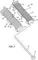
- FIGS. 1A and 1B show a perspective view and a side view, respectively, of a dry coal extrusion pump 10 for transporting pulverized dry coal.
- Pump 10 has increased efficiency by eliminating shear failure zones and flow stagnation zones within pump 10. Flow stagnation zones occur where pulverized dry coal is driven into walls at substantially right angles or impinged by other pulverized dry coal moving in the opposite direction. By substantially reducing or eliminating shear failure zones and flow stagnation zones, the mechanical efficiency of pump 10 can approach approximately 80%.
- pump 10 is capable of pumping pulverized dry coal into gas pressure tanks with internal pressures of over 1200 pounds per square inch absolute (8.27 MPa).
- pump 10 is discussed as transporting pulverized dry coal, pump 10 may transport any dry particulate material and may be used in various industries, including, but not limited to the following markets: petrochemical, electrical power, food, and agricultural.
- Pump 10 generally includes inlet 12, passageway 14, outlet 16, first load beam 18a, second load beam 18b, first scraper seal 20a, second scraper seal 20b, first drive assembly 22a, second drive assembly 22b, valve 24, and end wall 26.
- Pulverized dry coal is introduced into pump at inlet 12, sent through passageway 14, and expelled from pump 10 at outlet 16.
- Passageway 14 is defined by first belt assembly 28a and second belt assembly 28b, which are positioned substantially parallel and opposed to each other.
- First belt assembly 28a is formed from belt links 30 connected to each other by link rotation axles 32 (shown in FIGS. 2A, 2B, and 2C ) and track wheels 34.
- Link rotation axles 32 allow belt links 30 to form a flat surface as well as allow belt links 30 to bend around first drive assembly 22a.
- First belt assembly 28a defines an inner section 36a in which first drive assembly 22a is located.
- Track wheels 34 cover ends of link rotation axles 32 and function to transfer the mechanical compressive loads normal to belt links 30 into load beam 18a.
- first belt assembly 28a is formed from between approximately thirty-two (32) and approximately fifty (50) belt links 30 and link rotation axles 32.
- First belt assembly 28a, together with second belt assembly 28b, pushes the pulverized dry coal through passageway 14.
- Second belt assembly 28b includes belt links 30, link rotation axles 32, track wheels 34, and second inner section 36b.
- Belt links 30, link rotation axles 32, track wheels 34, and second inner section 36b are connected and function in the same manner as belt links 30, link rotation axles 32, track wheels 34, and first inner section 36a of first belt assembly 28a.
- First and second load beams 18a and 18b are positioned within first belt assembly 16a and second belt assembly 28b, respectively.
- First load beam 18a carries the mechanical load from first belt assembly 28a and maintains the section of first belt assembly 28a defining passageway 14 in a substantially linear form.
- the pulverized dry coal being transported through passageway 14 creates solid stresses on first belt assembly 28a in both a compressive outward direction away from passageway 14 as well as in a shearing upward direction toward inlet 12.
- the compressive outward loads are carried from belt links 30 into link rotation axles 32, into track wheels 34, and into first load beam 18a.
- First load beam 18a thus prevents first belt assembly 28a from collapsing into first interior section 36a of first belt assembly 28a as the dry pulverized coal is transported through passageway 14.
- the shearing upward loads are transferred from belt links 30 directly into drive sprockets 38a and 38b and drive assembly 22a.
- Second load beam 18b is formed and functions in the same manner as first load beam 18a to maintain second belt assembly 28a in a substantially linear form at passageway 14 and to transfer outward compressive and upward shearing loads from belt links 30 to second load beam 18b, drive sprockets 38a and 38b, and second drive assembly 22b.
- First scraper seal 20a and second scraper seal 20b are positioned proximate passageway 14 and outlet 16.
- First belt assembly 28a and first scraper seal 20a form a seal between pump 10 and the outside atmosphere.
- the exterior surface of first scraper seal 20a is designed to make a small angle with the straight section of first belt assembly 28a in order to scrape the pulverized dry coal stream off from moving first belt assembly 28a. The angle prevents pulverized dry coal stagnation that may lead to low pump mechanical efficiencies.
- first scraper seal 20a makes a 15 degree angle with the straight section of first belt assembly 28a.
- First scraper seal 20a may be made of any suitable material, including, but not limited to, hardened tool steel.
- Second scraper seal 20b is formed and functions in the same manner as first scraper seal 20a to prevent stagnation at second belt assembly 28b of pump 10.
- First drive assembly 22a is positioned within first interior section 36a of first belt assembly 28a and drives first belt assembly 28a in a first direction.
- First drive assembly 22a includes at least two drive sprockets 38a and 38b positioned at opposing ends of first belt assembly 28a.
- Each of drive sprockets 38a and 38b has a generally circular shaped base 40 with a plurality of sprocket teeth 42 protruding from base 40.
- Sprockets 42 interact with first belt assembly 28a and drives first belt assembly 28a around drive sprockets 38a and 38b.
- first drive assembly 22a rotates first belt assembly 28a at a rate of between approximately 1 foot per second (0.3 m/s) and approximately 5 feet per second (ft/s) (1.5 m/s).
- First drive assembly 22a preferably rotates first belt assembly 28a at a rate of approximately 2 ft/s (0.6 m/s).
- second drive assembly 22b includes at least two drive sprockets 38a and 38b positioned within second interior section 36b of second belt assembly 28b for driving second belt assembly 28b.
- Second drive assembly 22b is formed and functions in the same manner as first drive assembly 22a, except that second drive assembly 22b drives second belt assembly 28b in a second direction.
- Valve 24 is positioned proximate outlet 16 of pump 10 and is switchable between an open position and a closed position.
- a slot 44 runs through valve 24 and controls whether the pulverized dry coal may pass through outlet 16 of pump 10 into a discharge tank (not shown) positioned beneath pump 10.
- the width of slot 44 is larger than outlet 16 between scraper seals 20a and 20b.
- Valve 24 is typically in the closed position when first and second belt assemblies 28a and 28b of pump 10 are not rotating. Valve 24 remains in the closed position as pump 10 starts up.
- valve 24 is rotated 90 degrees to the open position (shown in FIG. 1B ).
- slot 44 is aligned with passageway 14 and outlet 16, allowing the pulverized dry coal in passageway 14 to flow through pump 10 to the discharge tank.
- valve 24 is a cylinder valve.
- the distance between sprockets 38a and 38b (in each of first and second drive assembly 22a and 22b), the convergence half angle ⁇ between load beams 18a and 18b, and the separation distance between scraper seals 20a and 20b are optimized to achieve the highest mechanical solids pumping efficiency possible for a particular pulverized material without incurring detrimental solids back flow and blowout inside pump 10.
- High mechanical solids pumping efficiencies are obtained when the mechanical work exerted on the solids by pump 10 is reduced to near isentropic (i.e., no solids slip) conditions.
- Detrimental solids back flow and blowout may be prevented by ensuring that the solids stress field within passageway 14 just upstream of scraper seals 20a and 20b is below the Mohr-Coulomb failure condition, or: ⁇ x ⁇ ⁇ y 2 4 + ⁇ xy 2 0.5 ⁇ c 1 ⁇ ⁇ cos ⁇ + ⁇ x ⁇ ⁇ y 2 sin ⁇ where the variable ⁇ xy is the solids shearing stress within passageway 14, ⁇ x is the compressive stress in the outward direction of passageway 14, ⁇ y is the compressive stress in the axial direction of passageway 14, ⁇ is the pulverized solids internal friction angle, and c is the pulverized solids coefficient of cohension.
- Additional compressive solids pressure, ( ⁇ x + ⁇ y )/2, for the prevention of slip just upstream of scraper seals 20a and 20b can be generated by: increasing the distance between sprockets 38a and 38b in each of first and second drive assembly 22a and 22b (for increased length of passageway 14), decreasing the width of passageway 14, or converging load beams 18a and 18b at a half angle, ⁇ , between 0 and 5 degrees.
- the set of geometrical values to be used for these parameters is determined by the set that achieves the minimum mechanical pump work.
- FIG. 2 shows a perspective view of belt link 30a and adjacent belt link 30b each having top surface 46, first side 48, second side 50, first end seal 52, second end seal 54, and protrusions 56.
- First and second end seals 52 and 54 of belt links 30 have an extended, trapezoidal shape.
- top surface 46 of belt links include a series of rectangular cavities 46c and ridges 46r. End seals 52 and 54 protrude higher than top surface 46 and act to seal the pressurized chamber of pump 10 from the outside atmosphere.
- Protrusions 56 extend from first and second sides 48 and 50 of belt links 30 such that protrusions 56 extending from second side 50 of belt link 30a align with protrusions 56 extending from first side 48 of adjacent belt link 30b.
- Link rotation axle 32 passes through apertures 58 extending through protrusions 56, allowing belt links 30 to pivot around link rotation axle 32 as belt links 30 travel around drive sprockets 38a and 38b (shown in FIGS. 1A and 1B ).
- Belt links 30 and link rotation axles 32 may be made of any suitable material, including, but not limited to, hardened tool steel.
- FIG. 3A shows an enlarged, partial side view of an exemplary embodiment of an interface of belt links 30 and first load beam 18a.
- FIG. 3B shows an enlarged, partial side view of an exemplary embodiment of belt link 30c and adjacent belt link 30d with first load beam 18a and track wheels 34 removed.
- FIG. 3C shows an enlarged, partial side view of an exemplary embodiment of an interface of belt links 30 and drive sprocket 38b with track wheels 34 removed.
- FIGS. 3A, 3B , and 3C will be discussed in conjunction with each other.
- Belt links 30 are held together by link rotation axles 32 and track wheels 34. As can be seen in FIG.
- link rotation axles 32 allow belt links 30 to form a flat surface between drive sprockets 38b when top surfaces 46 of adjacent belt links 30a and 30b are aligned with each other.
- the flat surface created by top surfaces 46 of belt links 30 eliminates solids flow stagnation zones by eliminating zones where pulverized dry coal is driven into walls at substantially right angles or impinged by other pulverized dry coal moving in the opposite direction.
- Belt links 30, link rotation axles 32, track wheels 34, second load beam 18b, and drive sprockets 38a and 38b of second drive assembly 22b and second belt assembly 28b interact and function in the same manner as belt links 30, link rotation axles 32, track wheels 34, first load beam 18a, and drive sprockets 38a and 38b of first drive assembly 22a and first belt assembly 28a.
- FIGS. 4A and 4B show a partial side view of first belt link assembly 28a interfacing drive sprocket 38b and a cross-sectional view of an interface of belt link 30 with first scraper seal 20a, respectively.
- FIG. 4A has first load beam 18a removed to better illustrate the cross-sectional view shown in FIG. 4B .
- interior surface 60 of first scraper seal 20a Similar to top surface 46 of belt link 30, interior surface 60 of first scraper seal 20a also includes a series of rectangular cavities 60c and ridges 60r.
- the series cavities 46c and ridges 46r of top surface 46 of belt link 30 interlock with the series of rectangular cavities 60c and ridges 60r of first scraper seal 20a to form a tight fitting seal that prevents the pulverized dry coal and high pressure gas at outlet 16 from blowing out of pump 10 to the outside ambient pressure environment.
- End seals 52 and 54 of belt links 30 also interact with end wall 26 to seal the pressurized chamber of pump 10 to the outside atmosphere.
- the labyrinth seal created by end seals 52 and 54 trap small pulverized dry coal particles and generate enough friction drag between the pulverized dry coal particles and end seals 52 and 54 to prevent excessive pulverized coal or pressurized gas from discharging at end wall 26.
- the moving/stationary interface between belt links 30 and end wall 26 are thus maintained at a minimum area by filling the region with the pulverized dry coal, which has a very large flow resistance within the interface region of belt links 30 and end wall 26.
- Belt links 30 and second scraper seal 20b interact and function in the same manner as belt links 30 and first scraper seal 20a to prevent pulverized dry coal and high pressure gas from escaping pump 10 to the atmosphere.
Landscapes
- Engineering & Computer Science (AREA)
- Mechanical Engineering (AREA)
- General Engineering & Computer Science (AREA)
- Structure Of Belt Conveyors (AREA)
- Structures Of Non-Positive Displacement Pumps (AREA)
- Filling Or Emptying Of Bunkers, Hoppers, And Tanks (AREA)
- Details Of Reciprocating Pumps (AREA)
- Reciprocating Pumps (AREA)
Claims (10)
- Pumpe (10) zum Transportieren eines partikelförmigen Materials, umfassend:einen Durchlass (14), der durch eine erste Förderbandanordnung (28a) und eine zweite Förderbandanordnung (28b) definiert ist, wobei jede der ersten Förderbandanordnung (28a) und der zweiten Förderbandanordnung (28b) einen Innenabschnitt (36a, 36b) aufweist und wobei die erste Förderbandanordnung (28a) und die zweite Förderbandanordnung (28b) einander gegenüberliegen;einen Einlass (12) zum Einführen des partikelförmigen Materials in den Durchlass (14);einen Auslass (16) zum Auswerfen des partikelförmigen Materials aus dem Durchlass (14);einen ersten Lastbalken (18a), der innerhalb des Innenabschnitts (36a) der ersten Förderbandanordnung (28a) positioniert ist;einen zweiten Lastbalken (18b), der innerhalb des Innenabschnitts der zweiten Förderbandanordnung positioniert ist;eine erste Abstreifdichtung (20a) und eine zweite Abstreifdichtung (20b), die nahe dem Durchlass (14) und dem Auslass (16) positioniert sind;eine erste Antriebsanordnung (22a), die innerhalb des Innenabschnitts (36a) der ersten Förderbandanordnung (28a) zum Antreiben der ersten Förderbandanordnung (28a) positioniert ist;eine zweite Antriebsanordnung (22b), die innerhalb des Innenabschnitts (36b) der zweiten Förderbandanordnung (28b) zum Antreiben der zweiten Förderbandanordnung (28b) positioniert ist, wobei jede der ersten Förderbandanordnung (28a) und der zweiten Förderbandanordnung (28b) eine Vielzahl von Förderbandverbindungselementen (30) umfasst, die schwenkbar durch eine Vielzahl von Verbindungselementdrehachsen (32) miteinander verbunden sind; undgekennzeichnet durch:
weiter umfassend eine erste Labyrinthdichtung bei einer Schnittstelle zwischen der ersten Förderbandanordnung (28a) und der ersten Abstreifdichtung (20a), und eine zweite Labyrinthdichtung bei einer Schnittstelle zwischen der zweiten Förderbandanordnung (28b) und der zweiten Abstreifdichtung (20b). - Pumpe nach Anspruch 1, wobei jede der ersten Antriebsanordnung (22a) und der zweiten Antriebsanordnung (22b) mindestens zwei Antriebszahnräder (38a, 38b) umfasst.
- Pumpe nach einem der vorstehenden Ansprüche, wobei die erste Abstreifdichtung (20a) und die zweite Abstreifdichtung (20b) in Kombination mit einem Teil des partikelförmigen Materials eine Dichtung für die Pumpe bilden.
- Pumpe nach einem der vorstehenden Ansprüche und weiter umfassend ein Ventil (24), das nahe dem Auslass (16) der Pumpe positioniert ist.
- Verfahren zum Pumpen von partikelförmigem Material mit der Pumpe (10) nach Anspruch 1, umfassend:Einspeisen der Partikel in den Einlass (12);Treiben der Partikel durch den Durchlass (14);Stützen des Durchlasses (14), während die Partikel durch den Durchlass (14) getrieben werden;Abstreifen von Partikeln von jeweils der ersten Förderbandanordnung (28a) und der zweiten Förderbandanordnung (28b); undAuswerfen der Partikel aus dem Auslass (16).
- Verfahren nach Anspruch 5, wobei Treiben der Partikel durch den Durchlass (14) ein Drehen der ersten Förderbandanordnung (28a) in einer ersten Richtung und ein Drehen der zweiten Förderbandanordnung (28b) in einer zweiten Richtung umfasst.
- Verfahren nach Anspruch 6, wobei ein Drehen der ersten Förderbandanordnung (28a) in der ersten Richtung und der zweiten Förderbandanordnung (28b) in der zweiten Richtung ein Verwenden einer Vielzahl von Antriebszahnrädern (38a, 38b) umfasst, die innerhalb der ersten Förderbandanordnung (28a) und der zweiten Förderbandanordnung (28b) positioniert sind.
- Verfahren nach Anspruch 5, 6 oder 7, wobei ein Stützen des Durchlasses (14) ein Positionieren des ersten Lastbalkens (18a) innerhalb der ersten Förderbandanordnung (28a) und ein Positionieren des zweiten Lastbalkens (18b) innerhalb der zweiten Förderbandanordnung (28b) umfasst.
- Verfahren nach Anspruch 8, wobei der erste Lastbalken (18a) und der zweite Lastbalken (18b) bei halben Winkeln zwischen etwa 0 und etwa 5 Grad zusammenlaufen.
- Verfahren nach einem der Ansprüche 5 bis 9, wobei ein Abstreifen von Partikeln von der ersten Förderbandanordnung (28a) und der zweiten Förderbandanordnung (28b) zur Bildung einer Dichtung ein Verwenden jeweils der ersten Abstreifdichtung (20a) und der zweiten Abstreifdichtung (20b) umfasst.
Applications Claiming Priority (1)
| Application Number | Priority Date | Filing Date | Title |
|---|---|---|---|
| US11/520,154 US7387197B2 (en) | 2006-09-13 | 2006-09-13 | Linear tractor dry coal extrusion pump |
Publications (3)
| Publication Number | Publication Date |
|---|---|
| EP1900941A2 EP1900941A2 (de) | 2008-03-19 |
| EP1900941A3 EP1900941A3 (de) | 2012-07-25 |
| EP1900941B1 true EP1900941B1 (de) | 2019-05-15 |
Family
ID=38290050
Family Applications (1)
| Application Number | Title | Priority Date | Filing Date |
|---|---|---|---|
| EP07252372.3A Ceased EP1900941B1 (de) | 2006-09-13 | 2007-06-12 | Linear angetriebene Pumpe |
Country Status (8)
| Country | Link |
|---|---|
| US (2) | US7387197B2 (de) |
| EP (1) | EP1900941B1 (de) |
| JP (2) | JP2008069003A (de) |
| CN (1) | CN101143649B (de) |
| AU (1) | AU2007201300B2 (de) |
| CA (1) | CA2591433C (de) |
| RU (1) | RU2452873C2 (de) |
| ZA (1) | ZA200704640B (de) |
Families Citing this family (52)
| Publication number | Priority date | Publication date | Assignee | Title |
|---|---|---|---|---|
| US7387197B2 (en) * | 2006-09-13 | 2008-06-17 | Pratt & Whitney Rocketdyne, Inc. | Linear tractor dry coal extrusion pump |
| JP4939311B2 (ja) * | 2007-06-08 | 2012-05-23 | 株式会社大生機械 | もやし類のほぐし供給装置 |
| US8596075B2 (en) | 2009-02-26 | 2013-12-03 | Palmer Labs, Llc | System and method for high efficiency power generation using a carbon dioxide circulating working fluid |
| US10018115B2 (en) | 2009-02-26 | 2018-07-10 | 8 Rivers Capital, Llc | System and method for high efficiency power generation using a carbon dioxide circulating working fluid |
| EP2411736B1 (de) | 2009-02-26 | 2019-06-05 | 8 Rivers Capital, LLC | Vorrichtung und verfahren zur verbrennung eines brennstoffs bei hohem druck und hoher temperatur und zugehörige(s) system und vorrichtung |
| US8631927B2 (en) * | 2009-06-19 | 2014-01-21 | Aerojet Rocketdyne Of De, Inc. | Track with overlapping links for dry coal extrusion pumps |
| US8967039B2 (en) * | 2009-12-01 | 2015-03-03 | Richard Moore | Avocado skinning and pulping device |
| US8950570B2 (en) * | 2009-12-15 | 2015-02-10 | Exxonmobil Research And Engineering Company | Passive solids supply system and method for supplying solids |
| US8739962B2 (en) * | 2009-12-15 | 2014-06-03 | Exxonmobil Research And Engineering Company | Active solids supply system and method for supplying solids |
| US8439185B2 (en) | 2010-04-13 | 2013-05-14 | Pratt & Whitney Rocketdyne, Inc. | Multiple moving wall dry coal extrusion pump |
| US8939278B2 (en) * | 2010-04-13 | 2015-01-27 | Aerojet Rocketdyne Of De, Inc. | Deconsolidation device for particulate material extrusion pump |
| US8851406B2 (en) | 2010-04-13 | 2014-10-07 | Aerojet Rocketdyne Of De, Inc. | Pump apparatus including deconsolidator |
| US9752776B2 (en) | 2010-08-31 | 2017-09-05 | Gas Technology Institute | Pressure vessel and method therefor |
| US20120067054A1 (en) | 2010-09-21 | 2012-03-22 | Palmer Labs, Llc | High efficiency power production methods, assemblies, and systems |
| US8869889B2 (en) | 2010-09-21 | 2014-10-28 | Palmer Labs, Llc | Method of using carbon dioxide in recovery of formation deposits |
| US8561791B2 (en) * | 2010-10-26 | 2013-10-22 | Pratt & Whitney Rocketdyne, Inc. | Balanced link for dry coal extrusion pumps |
| US8307974B2 (en) | 2011-01-21 | 2012-11-13 | United Technologies Corporation | Load beam unit replaceable inserts for dry coal extrusion pumps |
| US8887649B2 (en) | 2011-02-10 | 2014-11-18 | General Electric Company | System to vent solid feed pump |
| US8544633B2 (en) | 2011-03-18 | 2013-10-01 | General Electric Company | Segmented solid feed pump |
| US9114933B2 (en) | 2011-03-18 | 2015-08-25 | General Electric Company | Segmented solid feed pump |
| US8893878B2 (en) | 2011-06-29 | 2014-11-25 | Aerojet Rocketdyne Of De, Inc. | Screw-fed pump system |
| ES2574263T3 (es) | 2011-11-02 | 2016-06-16 | 8 Rivers Capital, Llc | Sistema de generación de energía y procedimiento correspondiente |
| CN107090317B (zh) | 2012-02-11 | 2019-10-25 | 八河流资产有限责任公司 | 具有封闭的循环骤冷的部分氧化反应 |
| CN105308320B (zh) * | 2013-06-13 | 2017-06-13 | 瓦斯技术研究所 | 具有柔性密封件的固体颗粒泵 |
| CN105339471B (zh) | 2013-06-27 | 2019-04-23 | 瓦斯技术研究所 | 具有旋转驱动器和一体链的颗粒泵 |
| JP6250332B2 (ja) | 2013-08-27 | 2017-12-20 | 8 リバーズ キャピタル,エルエルシー | ガスタービン設備 |
| US9932974B2 (en) * | 2014-06-05 | 2018-04-03 | Gas Technology Institute | Duct having oscillatory side wall |
| TWI691644B (zh) | 2014-07-08 | 2020-04-21 | 美商八河資本有限公司 | 具改良效率之功率生產方法及系統 |
| KR102445857B1 (ko) | 2014-09-09 | 2022-09-22 | 8 리버스 캐피탈, 엘엘씨 | 동력 생산 시스템 및 방법으로부터 저압의 액체 이산화탄소의 생산 |
| US11231224B2 (en) | 2014-09-09 | 2022-01-25 | 8 Rivers Capital, Llc | Production of low pressure liquid carbon dioxide from a power production system and method |
| US11686258B2 (en) | 2014-11-12 | 2023-06-27 | 8 Rivers Capital, Llc | Control systems and methods suitable for use with power production systems and methods |
| MA40950A (fr) | 2014-11-12 | 2017-09-19 | 8 Rivers Capital Llc | Systèmes et procédés de commande appropriés pour une utilisation avec des systèmes et des procédés de production d'énergie |
| US10961920B2 (en) | 2018-10-02 | 2021-03-30 | 8 Rivers Capital, Llc | Control systems and methods suitable for use with power production systems and methods |
| ES2898863T3 (es) | 2015-06-15 | 2022-03-09 | 8 Rivers Capital Llc | Sistema y método para la puesta en marcha de una planta de producción de energía |
| CN105151641A (zh) * | 2015-09-09 | 2015-12-16 | 苏州艾隆科技股份有限公司 | 一种新型转运装置 |
| CN109072104B (zh) | 2016-02-18 | 2021-02-26 | 八河流资产有限责任公司 | 用于包括甲烷化处理的发电系统和方法 |
| JP7001608B2 (ja) | 2016-02-26 | 2022-01-19 | 8 リバーズ キャピタル,エルエルシー | 電力プラントを制御するためのシステムおよび方法 |
| CN105731101B (zh) * | 2016-03-10 | 2019-03-15 | 安徽省全椒未来饲料有限责任公司 | 一种易于更换的饲料颗粒机的快速出料结构 |
| AU2017329061B2 (en) | 2016-09-13 | 2023-06-01 | 8 Rivers Capital, Llc | System and method for power production using partial oxidation |
| CN106743678B (zh) * | 2016-11-11 | 2024-05-28 | 航天长征化学工程股份有限公司 | 一种翻板式齿带粉体输送装置 |
| CN106398770A (zh) * | 2016-11-11 | 2017-02-15 | 航天长征化学工程股份有限公司 | 一种履带式粉煤加压输送装置 |
| WO2019043556A1 (en) | 2017-08-28 | 2019-03-07 | 8 Rivers Capital, Llc | OPTIMIZING THE LOW ENERGY HEAT OF SUPERCRITICAL CO2 POWER CYCLES WITH RECOVERY |
| JP7291157B2 (ja) | 2018-03-02 | 2023-06-14 | 8 リバーズ キャピタル,エルエルシー | 二酸化炭素作動流体を用いた電力生成のためのシステムおよび方法 |
| US11371494B2 (en) * | 2018-10-02 | 2022-06-28 | Gas Technology Institute | Solid particulate pump |
| CN109997468B (zh) * | 2019-04-18 | 2020-07-24 | 济南华庆农业机械科技有限公司 | 一种两级提料单粒取种装置及方法 |
| KR102163230B1 (ko) * | 2019-04-30 | 2020-10-08 | 고등기술연구원연구조합 | 무한궤도 타입의 고압 분체연료 연속 공급장치 |
| US11440053B1 (en) * | 2019-09-24 | 2022-09-13 | Nick Rocksvold | Particulate removal device |
| ES3026689T3 (en) | 2019-10-22 | 2025-06-11 | 8 Rivers Capital Llc | Control schemes for thermal management of power production systems and methods |
| CN112169876B (zh) * | 2020-09-19 | 2021-09-03 | 嵇明军 | 一种涂料自动化粉碎处理设备 |
| CN115072396B (zh) * | 2022-07-14 | 2023-12-22 | 中煤科工智能储装技术有限公司 | 一种能够拼接组合的散料地平取料机和方法 |
| CN116465532B (zh) * | 2023-05-12 | 2025-12-12 | 西安理工大学 | 基于数字钻技术的岩层水平地应力测定方法 |
| CN120207828B (zh) * | 2025-05-06 | 2026-01-06 | 盛和资源(连云港)新材料科技有限公司 | 一种捕收剂生产专用传输装置 |
Citations (1)
| Publication number | Priority date | Publication date | Assignee | Title |
|---|---|---|---|---|
| JPH0440725U (de) * | 1990-08-07 | 1992-04-07 |
Family Cites Families (35)
| Publication number | Priority date | Publication date | Assignee | Title |
|---|---|---|---|---|
| US1011589A (en) * | 1911-02-18 | 1911-12-12 | Ames Steel Lath Company | Feed device for sheet-metal-expanding machines. |
| FR514133A (fr) * | 1919-05-20 | 1921-03-03 | Buhler Freres | Appareil de transport |
| US1505757A (en) * | 1922-10-14 | 1924-08-19 | John J Warren | Apparatus for grinding wood pulp |
| US1740821A (en) * | 1928-07-30 | 1929-12-24 | Louise Kneuper | Apparatus for lifting viscous fluids |
| US2380144A (en) * | 1944-09-27 | 1945-07-10 | Hoyt H Bohannon | Pump |
| GB733280A (en) * | 1953-04-22 | 1955-07-06 | Thomas Locker And Company Ltd | Improvements in conveyor belts |
| GB1080882A (en) * | 1963-06-13 | 1967-08-23 | Amf Internat Ltd | Improvements relating to endless band conveyors |
| FR2147859B1 (de) * | 1971-08-04 | 1974-03-29 | Legrand Marcel | |
| SU468841A1 (ru) * | 1972-12-22 | 1975-04-30 | Предприятие П/Я А-7255 | Крутонаклонный ленточный конвейер |
| US3844398A (en) * | 1973-01-15 | 1974-10-29 | G Pinat | Self-centering dual belt conveyor |
| SU548494A1 (ru) * | 1974-01-04 | 1977-02-28 | Центральный Научно-Исследовательский Институт Фанеры | Пластинчатый конвейер |
| US4069911A (en) * | 1975-04-17 | 1978-01-24 | Amf Incorporated | Band conveyor |
| US4159886A (en) * | 1978-02-02 | 1979-07-03 | The Babcock & Wilcox Company | Pressurized conveyor |
| US4516674A (en) | 1981-07-20 | 1985-05-14 | Donald Firth | Method and apparatus for conveying and metering solid material |
| DE3316857A1 (de) * | 1983-05-07 | 1984-11-08 | Kupfermühle Holztechnik GmbH, 6430 Bad Hersfeld | Mehrseiten-hobelmaschine |
| IN161455B (de) * | 1983-08-17 | 1987-12-05 | Continental Conveyor & Equip | |
| SU1234303A1 (ru) * | 1984-12-12 | 1986-05-30 | Предприятие П/Я А-1872 | Конвейер дл спуска сыпучего груза |
| US5051041A (en) | 1990-03-05 | 1991-09-24 | Stamet, Inc. | Multiple-choke apparatus for transporting and metering particulate material |
| US4988239A (en) * | 1990-03-05 | 1991-01-29 | Stamet, Inc. | Multiple-choke apparatus for transporting and metering particulate material |
| US5094340A (en) * | 1990-11-16 | 1992-03-10 | Otis Engineering Corporation | Gripper blocks for reeled tubing injectors |
| US5551553A (en) | 1992-08-11 | 1996-09-03 | Stamet, Inc. | Angled disk drive apparatus for transporting and metering particulate material |
| US5355993A (en) | 1993-06-11 | 1994-10-18 | Hay Andrew G | Grooved disk drive apparatus and method for transporting and metering particulate material |
| US5485909A (en) | 1993-08-31 | 1996-01-23 | Stamet, Inc. | Apparatus with improved inlet and method for transporting and metering particulate material |
| US5497873A (en) | 1993-12-08 | 1996-03-12 | Stamet, Inc. | Apparatus and method employing an inlet extension for transporting and metering fine particulate and powdery material |
| US5492216A (en) * | 1994-03-09 | 1996-02-20 | Simplimatic Engineering Company | Method and apparatus for transferring containers while maintaining vertical orientation |
| US5435433A (en) * | 1994-03-14 | 1995-07-25 | Project Services Group, Inc. | Dual belt conveyor with product isolation |
| US6213289B1 (en) | 1997-11-24 | 2001-04-10 | Stamet, Incorporation | Multiple channel system, apparatus and method for transporting particulate material |
| NL1008070C2 (nl) * | 1998-01-19 | 1999-07-20 | Mcc Nederland | Transportsysteem voor het transporteren van producten, alsmede overschuifinrichting. |
| DE19829433A1 (de) * | 1998-07-01 | 2000-01-05 | Kolbus Gmbh & Co Kg | Fördervorrichtung für Buchbindemaschinen |
| AT406668B (de) * | 1998-10-05 | 2000-07-25 | Starlinger & Co Gmbh | Vorrichtung zur übernahme und beförderung von gegenständen |
| US6583060B2 (en) * | 2001-07-13 | 2003-06-24 | Micron Technology, Inc. | Dual depth trench isolation |
| US6719043B2 (en) * | 2002-05-10 | 2004-04-13 | Halliburton Energy Services, Inc. | Coiled tubing injector apparatus |
| US7717046B2 (en) | 2005-04-29 | 2010-05-18 | Pratt & Whitney Rocketdyne, Inc. | High pressure dry coal slurry extrusion pump |
| CN1318550C (zh) * | 2005-07-01 | 2007-05-30 | 煤炭科学研究总院北京煤化工研究分院 | 一种干煤粉加压气化方法 |
| US7387197B2 (en) * | 2006-09-13 | 2008-06-17 | Pratt & Whitney Rocketdyne, Inc. | Linear tractor dry coal extrusion pump |
-
2006
- 2006-09-13 US US11/520,154 patent/US7387197B2/en not_active Ceased
-
2007
- 2007-03-26 AU AU2007201300A patent/AU2007201300B2/en active Active
- 2007-06-08 RU RU2007121726/11A patent/RU2452873C2/ru not_active IP Right Cessation
- 2007-06-11 CA CA2591433A patent/CA2591433C/en not_active Expired - Fee Related
- 2007-06-11 CN CN2007101264543A patent/CN101143649B/zh not_active Expired - Fee Related
- 2007-06-12 EP EP07252372.3A patent/EP1900941B1/de not_active Ceased
- 2007-06-12 JP JP2007154906A patent/JP2008069003A/ja active Pending
- 2007-06-13 ZA ZA200704640A patent/ZA200704640B/xx unknown
-
2008
- 2008-12-01 US US12/326,066 patent/USRE42844E1/en active Active
-
2012
- 2012-10-24 JP JP2012234266A patent/JP2013018656A/ja active Pending
Patent Citations (1)
| Publication number | Priority date | Publication date | Assignee | Title |
|---|---|---|---|---|
| JPH0440725U (de) * | 1990-08-07 | 1992-04-07 |
Also Published As
| Publication number | Publication date |
|---|---|
| EP1900941A2 (de) | 2008-03-19 |
| CA2591433C (en) | 2016-07-26 |
| JP2008069003A (ja) | 2008-03-27 |
| AU2007201300A1 (en) | 2008-04-03 |
| CN101143649A (zh) | 2008-03-19 |
| RU2007121726A (ru) | 2008-12-20 |
| CN101143649B (zh) | 2012-06-13 |
| RU2452873C2 (ru) | 2012-06-10 |
| JP2013018656A (ja) | 2013-01-31 |
| USRE42844E1 (en) | 2011-10-18 |
| US20080060914A1 (en) | 2008-03-13 |
| US7387197B2 (en) | 2008-06-17 |
| ZA200704640B (en) | 2008-08-27 |
| AU2007201300B2 (en) | 2013-02-21 |
| CA2591433A1 (en) | 2008-03-13 |
| EP1900941A3 (de) | 2012-07-25 |
Similar Documents
| Publication | Publication Date | Title |
|---|---|---|
| EP1900941B1 (de) | Linear angetriebene Pumpe | |
| US8739962B2 (en) | Active solids supply system and method for supplying solids | |
| US8950570B2 (en) | Passive solids supply system and method for supplying solids | |
| EP2377788B1 (de) | Trockenkohleextrusionspumpe mit mehrfachen beweglichen Wänden | |
| EP2443052B1 (de) | Kette mit überlappenden gliedern für magerkohleextrusionspumpen | |
| CN102602672B (zh) | 用于干煤挤压泵的载荷梁单元可更换插入件 | |
| US8561791B2 (en) | Balanced link for dry coal extrusion pumps | |
| US6491156B1 (en) | Fluid plenum conveyor trough and method for fabricating and joining the same | |
| RU2550866C2 (ru) | Линейное протяжное экструдерное устройство для сухого угля | |
| CN217147874U (zh) | 一种颗粒与粉料形成的混合料下料装置 | |
| Sprouse et al. | Linear tractor dry coal extrusion pump | |
| CN211444182U (zh) | 一种气动输送y型三通 | |
| JP2749613B2 (ja) | 土砂の空気搬送方法及び装置 | |
| EP0951435A1 (de) | Rohrtrogartiger förderer für das pneumatische fördern von staubförmigem material |
Legal Events
| Date | Code | Title | Description |
|---|---|---|---|
| PUAI | Public reference made under article 153(3) epc to a published international application that has entered the european phase |
Free format text: ORIGINAL CODE: 0009012 |
|
| AK | Designated contracting states |
Kind code of ref document: A2 Designated state(s): AT BE BG CH CY CZ DE DK EE ES FI FR GB GR HU IE IS IT LI LT LU LV MC MT NL PL PT RO SE SI SK TR |
|
| AX | Request for extension of the european patent |
Extension state: AL BA HR MK YU |
|
| PUAL | Search report despatched |
Free format text: ORIGINAL CODE: 0009013 |
|
| AK | Designated contracting states |
Kind code of ref document: A3 Designated state(s): AT BE BG CH CY CZ DE DK EE ES FI FR GB GR HU IE IS IT LI LT LU LV MC MT NL PL PT RO SE SI SK TR |
|
| AX | Request for extension of the european patent |
Extension state: AL BA HR MK RS |
|
| RIC1 | Information provided on ipc code assigned before grant |
Ipc: F04B 19/20 20060101ALI20120619BHEP Ipc: B65G 15/14 20060101AFI20120619BHEP Ipc: F04D 33/00 20060101ALI20120619BHEP |
|
| 17P | Request for examination filed |
Effective date: 20130121 |
|
| AKX | Designation fees paid |
Designated state(s): DE FR |
|
| RAP1 | Party data changed (applicant data changed or rights of an application transferred) |
Owner name: AEROJET ROCKETDYNE OF DE, INC. |
|
| RAP1 | Party data changed (applicant data changed or rights of an application transferred) |
Owner name: GAS TECHNOLOGY INSTITUTE |
|
| STAA | Information on the status of an ep patent application or granted ep patent |
Free format text: STATUS: EXAMINATION IS IN PROGRESS |
|
| 17Q | First examination report despatched |
Effective date: 20170220 |
|
| 17Q | First examination report despatched |
Effective date: 20170308 |
|
| GRAP | Despatch of communication of intention to grant a patent |
Free format text: ORIGINAL CODE: EPIDOSNIGR1 |
|
| STAA | Information on the status of an ep patent application or granted ep patent |
Free format text: STATUS: GRANT OF PATENT IS INTENDED |
|
| INTG | Intention to grant announced |
Effective date: 20181122 |
|
| GRAS | Grant fee paid |
Free format text: ORIGINAL CODE: EPIDOSNIGR3 |
|
| GRAA | (expected) grant |
Free format text: ORIGINAL CODE: 0009210 |
|
| STAA | Information on the status of an ep patent application or granted ep patent |
Free format text: STATUS: THE PATENT HAS BEEN GRANTED |
|
| AK | Designated contracting states |
Kind code of ref document: B1 Designated state(s): DE FR |
|
| REG | Reference to a national code |
Ref country code: DE Ref legal event code: R096 Ref document number: 602007058366 Country of ref document: DE |
|
| REG | Reference to a national code |
Ref country code: DE Ref legal event code: R097 Ref document number: 602007058366 Country of ref document: DE |
|
| PLBE | No opposition filed within time limit |
Free format text: ORIGINAL CODE: 0009261 |
|
| STAA | Information on the status of an ep patent application or granted ep patent |
Free format text: STATUS: NO OPPOSITION FILED WITHIN TIME LIMIT |
|
| 26N | No opposition filed |
Effective date: 20200218 |
|
| PG25 | Lapsed in a contracting state [announced via postgrant information from national office to epo] |
Ref country code: FR Free format text: LAPSE BECAUSE OF NON-PAYMENT OF DUE FEES Effective date: 20190715 |
|
| PGFP | Annual fee paid to national office [announced via postgrant information from national office to epo] |
Ref country code: DE Payment date: 20210629 Year of fee payment: 15 |
|
| REG | Reference to a national code |
Ref country code: DE Ref legal event code: R119 Ref document number: 602007058366 Country of ref document: DE |
|
| PG25 | Lapsed in a contracting state [announced via postgrant information from national office to epo] |
Ref country code: DE Free format text: LAPSE BECAUSE OF NON-PAYMENT OF DUE FEES Effective date: 20230103 |