EP1901972B1 - Device for dispensing a controlled dose of a flowable material - Google Patents
Device for dispensing a controlled dose of a flowable material Download PDFInfo
- Publication number
- EP1901972B1 EP1901972B1 EP06786376A EP06786376A EP1901972B1 EP 1901972 B1 EP1901972 B1 EP 1901972B1 EP 06786376 A EP06786376 A EP 06786376A EP 06786376 A EP06786376 A EP 06786376A EP 1901972 B1 EP1901972 B1 EP 1901972B1
- Authority
- EP
- European Patent Office
- Prior art keywords
- plunger
- guide track
- guide pin
- flowable material
- guide
- Prior art date
- Legal status (The legal status is an assumption and is not a legal conclusion. Google has not performed a legal analysis and makes no representation as to the accuracy of the status listed.)
- Active
Links
Images


Classifications
-
- B—PERFORMING OPERATIONS; TRANSPORTING
- B65—CONVEYING; PACKING; STORING; HANDLING THIN OR FILAMENTARY MATERIAL
- B65D—CONTAINERS FOR STORAGE OR TRANSPORT OF ARTICLES OR MATERIALS, e.g. BAGS, BARRELS, BOTTLES, BOXES, CANS, CARTONS, CRATES, DRUMS, JARS, TANKS, HOPPERS, FORWARDING CONTAINERS; ACCESSORIES, CLOSURES, OR FITTINGS THEREFOR; PACKAGING ELEMENTS; PACKAGES
- B65D83/00—Containers or packages with special means for dispensing contents
- B65D83/76—Containers or packages with special means for dispensing contents for dispensing fluent contents by means of a piston
-
- C—CHEMISTRY; METALLURGY
- C11—ANIMAL OR VEGETABLE OILS, FATS, FATTY SUBSTANCES OR WAXES; FATTY ACIDS THEREFROM; DETERGENTS; CANDLES
- C11D—DETERGENT COMPOSITIONS; USE OF SINGLE SUBSTANCES AS DETERGENTS; SOAP OR SOAP-MAKING; RESIN SOAPS; RECOVERY OF GLYCEROL
- C11D17/00—Detergent materials or soaps characterised by their shape or physical properties
- C11D17/04—Detergent materials or soaps characterised by their shape or physical properties combined with or containing other objects
- C11D17/041—Compositions releasably affixed on a substrate or incorporated into a dispensing means
- C11D17/046—Insoluble free body dispenser
-
- E—FIXED CONSTRUCTIONS
- E03—WATER SUPPLY; SEWERAGE
- E03D—WATER-CLOSETS OR URINALS WITH FLUSHING DEVICES; FLUSHING VALVES THEREFOR
- E03D9/00—Sanitary or other accessories for lavatories ; Devices for cleaning or disinfecting the toilet room or the toilet bowl; Devices for eliminating smells
- E03D9/02—Devices adding a disinfecting, deodorising, or cleaning agent to the water while flushing
- E03D2009/026—Devices adding a disinfecting, deodorising, or cleaning agent to the water while flushing using a gel-form substance
Definitions
- This invention relates to a device for dispensing controlled doses of a flowable material, and more particularly to a device for applying controlled doses of a flowable adhesive material to a surface according to the preamble of claim 1.
- U.S. Patent No. 6,667,286 describes a viscous gel-like substance that may be applied directly to the inner surface of a toilet bowl for cleaning and/or disinfecting and/or fragrancing the toilet bowl.
- the substance can be applied from a suitable applicator directly onto the inner surface of the toilet bowl, to which the substance adheres.
- the substance remains on the inner surface of the toilet bowl even after being contacted with flush water, and typically the substance is only flushed away completely after a large number of flushes.
- the substance is also suitable for application to other surfaces such as urinals, lavatory or industrial sinks, showers, bathtubs, dishwashing machines and the like.
- PCT International Patent Application WO 03/043906 discloses a syringe-type dispensing device suitable for use in applying such adhesive gel-like substances to a surface.
- PCT International Patent Application WO 2004/043825 also discloses a syringe-type dispensing device for applying such adhesive gel-like substances to a surface.
- U.S. Patent 4,445,626 represents the closest prior art and describes a metering device for dispensing selected amounts of viscous material:
- a cylindrical container for viscous material has a first open base end of a first diameter and a spaced opposite closed base end with an opening therethrough of a second diameter smaller than the first diameter.
- a cylindrical plunger of a third diameter slightly smaller than the first diameter is coaxially slidably mounted in the container in a snug manner.
- the plunger has a closed plunger head perpendicular to its axis.
- a positioning device selectively positions the plunger and the container relative to each other at a plurality of different axial positions The plunger, at each of the axial positions, forces a predetermined measured amount of the viscous material out of the opening of the container.
- a device applies controlled and accurate doses of a flowable adhesive material to a surface.
- the device includes a tubular body and a plunger.
- the body has a wall defining a cavity, and the body has a first open end and an opposite second end having a dispensing orifice.
- a flowable adhesive material is contained in the cavity of the body filled between the dispensing orifice and the first end.
- the plunger has an outer sleeve dimensioned for surrounding at least a section of the body and an inner pushing structure dimensioned for axial movement in the cavity of the body.
- the device has means for indexed positioning of the second end of the body and an inner end of the inner pushing structure of the plunger relative to each other to provide controlled doses of the flowable adhesive material such that the controlled unitized doses of the flowable adhesive material may be applied to the surface when the plunger (also called the "holder") is moved toward the body by a user.
- An end of the outer sleeve of the plunger may be outwardly flaring to provide for a shield for the user's hand and a good grip.
- the second end of the body may have an end wall having a concave inner surface
- the inner end of the pushing structure of the plunger may have a convex outer surface that substantially conforms to the concave inner surface of the end wall of the second end of the body such that substantially all material is extruded from the body and out of the dispensing orifice.
- the inner end of the pushing structure may comprise a piston head.
- the means for indexed positioning of the body and plunger during use may comprise a guide track and a guide pin that travels stepwise in the guide track.
- One of the guide track and the guide pin may be located on an outer surface of the body, and the other of the guide track and the guide pin may be located on an inner surface of the outer sleeve of the plunger.
- the guide pin is located on an inner surface of the outer sleeve of the plunger, and the guide track is located on the outer surface of the body.
- the means for indexed positioning comprises a guide track and a guide pin that travels stepwise in the guide track wherein the guide pin is located on an inner surface of the body and the guide track is located on the plunger.
- the means for indexed positioning comprises a guide track and a guide pin that travels stepwise in the guide track where the guide track has a serpentine path.
- the guide track may include at least one resilient arm for moving the guide pin laterally along a length of the guide track after the guide pin has been stopped in the guide track at the end of a dose. Specifically, each resilient arm moves the guide pin laterally after the guide pin contacts a shoulder at a perimeter region of the guide track.
- the means for indexed positioning comprises a guide track and a guide pin that travels stepwise in the guide track wherein the guide pin is movably located on an outer surface of the body and the guide track is located on the plunger wherein the guide track comprises a plurality of aligned throughholes dimensioned to receive the guide pin.
- the means for indexed positioning provides for delivery of controlled accurate unitized doses of material as the body and plunger move in an axial indexed stepwise controlled manner in relation to each other.
- the device may further include means for creating a sound for audible feedback as the guide pin travels stepwise in the guide track.
- the means for creating a sound comprises a click pin and at least one click slot.
- the click pin may be located on the outer sleeve of the plunger and each click slot may be located in the wall of the body.
- Each click slot allows the click pin to spring inward to cause a clicking sound from contacting the body as the guide pin travels stepwise in the guide track.
- Each clicking sound is synchronized with the end of each dose of the material.
- the pushing structure of the plunger includes a pushing frame and a separate piston head, and the pushing frame engages the piston head.
- the pushing structure includes a separate piston, and an inner surface of the pushing structure engages the piston.
- the body includes a shroud that extends away from the second end of the body and surrounds the dispensing orifice.
- the shroud restricts the outward spread of the material inside the shroud when the material is applied to a surface.
- the bottom edge of the shroud provides for contact with the surface on which the material is being dispensed, and the distance between the dispensing orifice and the bottom edge of the shroud defines the thickness and diameter of flowable material dispensed onto the surface.
- a refill for the device provides for dispensing controlled doses of a flowable material
- the device includes a plunger having an outer sleeve with an inwardly directed guide pin.
- the refill includes a tubular body having a wall defining a cavity.
- the body has a first open end and an opposite second end having a dispensing orifice, and the body has a guide track in an outer surface of the body.
- a flowable material is contained in the cavity, and a piston head is optionally located in the first open end of the cavity depending on the structure of the plunger.
- the guide track is structured such that the guide pin travels stepwise in the guide track.
- the flowable material may be an adhesive gel suitable for application to a hard surface that can be cleaned with water washing over the hard surface, or an adhesive gel suitable for application to a toilet, urinal, bathtub or shower.
- the guide track may have a serpentine path, and may include at least one resilient arm for moving the guide pin laterally along a length of the guide track.
- the body may include a shroud that extends away from the second end of the body and surrounds the dispensing orifice. The first open end of the body and/or the dispensing orifice may be covered with a removable seal, and preferably the dispensing orifice is circular for ease of application of a circular disc of material to a surface.
- a refill for the device provides for dispensing controlled doses of a flowable material
- the device includes a plunger having an outer sleeve with a guide track comprising throughholes in the outer sleeve of the plunger.
- the refill includes a tubular body having a wall defining a cavity.
- the body has a first open end and an opposite second end having a dispensing orifice.
- the body has a guide pin movably attached to an outer surface of the body, and a flowable material in the cavity.
- the guide pin is dimensioned to be received in the throughholes of the guide track.
- the dispensing device has a body, a plunger, a piston head and a cap.
- the body has two sets of tracks at a certain pitch to give the desired dosage. Each set has two tracks of different configuration, first, a serpentine track with shoulders to stop the plunger when the plunger is pushed, and second, a channel to provide an audible feedback (a click) to the user.
- the body also has a piston head inserted within the body such that a convex outer surface of the piston head is in phase with a concave shape of the inside of the dispensing orifice.
- the distance between the contact surface of the shroud and the dispensing orifice is important in defining the diameter and thickness of the material applied to the surface, which in turn defines length of life and efficacy of the material applied to the surface.
- the piston head is structurally configured to accept a pushing structure of the plunger.
- the dispensing device has a body, a plunger, a piston head and a cap.
- the plunger has a guide track at a certain pitch to give the desired dosage.
- the guide track has a serpentine track with six shoulders to stop a guide pin on the body when the plunger is pushed.
- the guide pin enters the guide track. The user will butt the contact surface of the shroud of the body against the hard surface and push the plunger causing the guide pin to move and stop at the next shoulder in the guide track to complete one dose.
- the dispensing device has a body, a plunger, a piston head and a cap.
- the outer sleeve of the plunger has six throughholes at a pitch to give the desired dose of material.
- a spring loaded pin of the body snaps into a first throughhole in the plunger. The user will butt the contact surface of the shroud of the body against the hard surface and push the plunger while pressing the head of the pin and causing the pin to move and snap into the next throughhole to complete one dose.
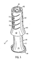
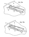
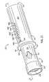
- Figure 1 is an upper right front perspective view showing a dispensing device according to the invention.
- Figure 2 is a front elevational view of the dispensing device of Figure 1 .
- Figure 3 is a right side view of the dispensing device of Figure 1 .
- Figure 4 is a top plan view of the dispensing device of Figure 1 .
- Figure 5 is a bottom plan view of the dispensing device of Figure 1 showing external details of the cap.
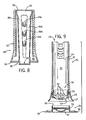
- Figure 6 is a front plan view of a flowable material containing body and a cap of the dispensing device of Figure 1 .
- Figure 7 is a rear plan view of the flowable material containing body and cap of Figure 6 .
- Figure 8 is a cross-sectional view of a plunger of the dispensing device taken along line 8-8 of Figure 3 .
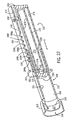
- Figure 9 is a cross-sectional view of the flowable material containing body, piston, and cap of the dispensing device taken along line 9-9 of Figure 3 .
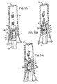
- Figures 10a-10g are cross-sectional views similar to Figure 9 showing the clicking operational features of the plunger indexing downward on the flowable material containing body of the dispensing device.
- Figure 11 is a detailed view taken from Figure 10a .
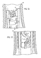
- Figure 12 is a detailed view showing the means for indexing the plunger on the flowable material containing body of the dispensing device.
- Figures 13a-13c are detailed views showing the movement of the guide pin in the guide track of the means for indexing the plunger on the flowable material containing body of the dispensing device.
- Figure 14 shows the use of the dispensing device in applying a controlled dose of a cleaning, disinfecting and/or fragrancing adhesive gel to the inner surface of a toilet bowl.
- Figures 15a-15d shows the steps in using the dispensing device to apply a controlled dose of a cleaning, disinfecting and/or fragrancing adhesive gel to the inner surface of a toilet bowl.
- Figure 16 is an upper right front perspective view showing a flowable material containing body and piston of a second embodiment of a dispensing device according to the invention.
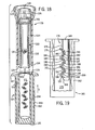
- Figure 17 is an upper right front perspective view showing a plunger of the second embodiment of the dispensing device of Figure 16 .
- Figure 18 is an exploded cross-sectional view of the flowable material containing body, piston and plunger of the second embodiment of a dispensing device of Figure 16 and 17 .
- Figure 19 is a cut out side elevational view of the plunger of Figure 17 .
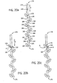
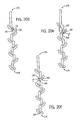
- Figures 20a-20f are detailed views showing the movement of the guide pin in the guide track of the means for indexing the plunger on the flowable material containing body of the dispensing device of Figures 16-19 .
- Figure 21 is a perspective view showing an assembled flowable material containing body and plunger of a third embodiment of a dispensing device according to the invention.
- Figure 22 is a cross-sectional view of the dispensing device of Figure 21 taken along line 22-22 of Figure 21 .
- a dispensing device 10 can accurately apply controlled unitized doses of a flowable adhesive material to a surface.
- the device 10 may be used for applying controlled doses of a cleaning, disinfecting and/or fragrancing flowable adhesive gel to the surface of a toilet, urinal, bathtub, shower or the like.
- a cleaning, disinfecting and/or fragrancing flowable adhesive gel is described in U.S. Patent No. 6,667,286 , which is incorporated herein by reference along with all other documents cited herein.
- Such a gel has a viscosity of at least 15,000 mPa.
- the device 10 includes a tubular body 20 that contains the flowable material and a plunger 60 that pushes the flowable material from the tubular body 20 onto the surface.
- a cap 54 covers the tubular body opening during storage.
- all of the components of the device 10 are constructed from a polymeric material such as translucent or opaque polyethylene or polypropylene.
- the body 20 has a generally tubular cylindrical wall 21 that defines a cavity 24 for containing the flowable material (which is not shown in Figure 9 ).
- the wall 21 has an inner surface 22 and an outer surface 23.
- the body 20 has a first anterior open end 25 and an opposite posterior end 26 that has a wall with a concave inner surface 27 and a circular dispensing orifice 28 (see Figure 15a ).
- the end 26 also has an outwardly flaring shroud 29 that surrounds the orifice 28.
- the cap 54 is provided for sealing off the orifice 28 during shipping, storage and between uses.
- the cap 54 includes an upward circular wall 55 that forms a well 56 which has a concave lower inner surface 57 that substantially conforms to the concave inner surface 27 of the end wall 26 of the body 20. This provides a tight seal between the cap 54 and the body 20. Ears 58 are provided on the cap 54 for ease of removal of the cap 54 from the body 20.
- the cap 54 may also be sized for engagement in a docking station that rests on a surface such as a floor.
- the plunger 60 has a generally tubular cylindrical outer sleeve 62 having an outer surface 63 and an inner surface 64.
- the outer sleeve 62 terminates in an outwardly flaring end 66.
- the outer sleeve 62 has cut out tabs 71 a, 71 b and 71 c formed by U-shaped slits that extend through the outer sleeve 62.
- Each of the cut out tabs 71 a, 71 b and 71 c has a guide pin that extends inward from the inner surface 64 of the outer sleeve 62. See, for example, Figure 12 , which shows guide pin 72c that extends inward from cut out tab 71 c.
- Figure 2 shows the inwardly directed guide pins 72a, 72b, 72c in phantom.
- the outer sleeve 62 also has cut out tabs 68a, 68b and 68c formed by U-shaped slits that extend through the outer sleeve 62.
- the cut out tabs 68a, 68b and 68c are 180 degrees opposite the cut out tabs 71 a, 71 b and 71 c.
- Cut out tabs 68a, 68b and 68c each have inwardly directed click pins 69a, 69b and 69c respectively (see Figure 10a ) that extend inward from the inner surface 64 of the outer sleeve 62.
- the same dimensioned pin is used on both sides of the plunger 60 for the guide pins 72a, 72b and 72c and click pins 69a, 69b, 69c to allow 180 degrees rotation thereby enabling the applicator to be assembled in both orientations.
- the function of the guide pins 72a, 72b and 72c and click pins 69a, 69b, 69c will be described below.
- the plunger 60 includes part of a pushing structure 80 that pushes the flowable material from the tubular body 20 through the orifice 28 and onto the surface.
- the pushing structure 80 includes an annular end wall 82 that is integral with the outer sleeve 62 of the plunger 60.
- An inwardly directed circumferential skirt 84 is integral with the end wall 82 of the plunger 60.
- Four circumferentially equally spaced slats 86a, 86b, 86c and 86d extend away from the skirt 84 forming a frame.
- the slats 86a, 86b, 86c and 86d are connected to a generally circular inner end wall 88 of the plunger 60. Rectangular notches 90 are provided in the inner end wall 88.
- a movable piston head 50 which forms part of the pushing structure 80, is positioned for sealing sliding movement within the cavity 24 of the body 20.
- the generally circular piston head 50 has a convex domed outer surface 51 and inner mounting flanges 52 extending away from the outer surface 51.
- the mounting flanges 52 engage the notches 90 in the inner end wall 88 to secure the piston head 50 to the inner end wall 88 of the pushing structure 80 of the plunger 60.
- the piston head 50 may also be formed as an integral part of the inner end wall 88.
- the plunger 60 is moved in direction D of Figures 2 and 3 such that flowable material contained in the body 20 between the piston head 50 and the end 26 of the body 20 is forced out of the dispensing orifice 28 of the body 20 and onto a surface.
- the device 10 is structured such that accurate unitized discrete controlled doses of the flowable material can be applied to a surface.
- the device includes means for indexed stepwise positioning of the end 26 of the body 20 and the inner end wall 88 (and attached piston head 50) of the inner pushing structure 80 of the plunger 60 relative to each other to provide controlled doses of the flowable adhesive material.
- One component of the means for indexed stepwise positioning is a guide track 30 in the outer surface 23 of the body 20.
- Another component of the means for indexed stepwise positioning is the set of guide pins 72a, 72b and 72c described above.
- the guide track 30 includes a downwardly converging open section 31, a first straight section 32, a first curved resilient arm 33, a first shoulder 34, a second straight section 35, a second curved resilient arm 36, a second shoulder 37 and a third straight section 38.
- the first curved resilient arm 33 and the second curved resilient arm 36 are also shown in Figure 12 .
- the downwardly converging open section 31, the first straight section 32, the first shoulder 34, the second straight section 35, the second shoulder 37 and the third straight section 38 are configured by way of a groove in the outer surface 23 of the end 25 of the body 20.
- the first curved resilient arm 33 and the second curved resilient arm 36 are configured by way of slits that go through the outer surface 23 of the end 25 of the body 20.
- each guide pin may be radiused to guide the pin on its way through the guide track 30.
- the body 20 and the plunger 60 may be assembled holding the body 20 and the plunger 60 in any orientation (e.g., downward, sidewise, diagonal, upward).
- the Figures show the plunger 60 being assembled over the body 20 in a downward direction D such that the outer sleeve 62 is positioned for surrounding at least a section the body 20 and the inner pushing structure 80 is positioned for axial movement in the cavity 24 of the body 20.
- the user After a user engages the guide pin 72c in the converging open section 31 of the guide track 30 as shown in the left hand illustration in Figure 13a , the user continues moving the plunger in direction D (see Figure 2 ) such that the guide pin 72c enters the first straight section 32 of the guide track 30.
- the user continues moving the plunger in direction D such that the guide pin 72c moves in the first straight section 32 of the guide track 30 and then contacts the first shoulder 34 of the guide track 30 as shown in the right hand illustration of Figure 13a .
- the first shoulder 34 stops movement of the plunger 60 in direction D. In this manner, the first straight section 32 and the first shoulder 34 of the guide track 30 provide a set distance for movement of the plunger 60 in relation to the body 20.
- the piston head 50 which forms the end of the pushing structure 80 of the plunger 60 as described above, moves the set distance in relation to the end 26 of the body 20 thereby forcing out a set amount of flowable material from the orifice 28 of the body 20 and onto the surface. Because of the resistance provided by the first shoulder 34, the user knows to stop pressing in direction D on the plunger 60.
- the guide pin 72c pushes the first resilient arm 33 in the direction R.
- the guide pin 72c contacts the first shoulder 34, it stops the movement in direction D, indicating to the user that one dose has been completely applied by stopping the downward movement.
- the first resilient arm 33 is able to move back in direction L (as shown in the left hand illustration of Figure 13b ) and position the guide pin 72c to enable the second dose to be executed.
- the piston head 50 which forms the end of the pushing structure 80 of the plunger 60 as described above, moves the set distance in relation to the end 26 of the body 20 thereby forcing out a second set amount of flowable material from the orifice 28 of the body 20 and onto the surface. Because of the resistance provided by the second shoulder 37, the user knows to stop pressing in direction D on the plunger 60.
- the guide pin 72c pushes the second resilient arm 36 in the direction L.
- the guide pin 72c contacts the second shoulder 37, it stops the movement in direction D, indicating to the user that one dose has been completely applied by stopping the downward movement.
- the second resilient arm 36 is able to move back in direction R (as shown in the left hand illustration of Figure 13c ) and position the guide pin 72c to enable the third dose to be executed.
- the user moves the plunger in direction D (see Figure 2 ) such that guide pin 72b moves downward in the first straight section 32 of the guide track 30 and the guide pin 72c moves downward in the third straight section 38 of the guide track 30.
- the user continues moving the plunger in direction D such that the guide pin 72b moves in the first straight section 32 of the guide track 30 and then contacts the first shoulder 34 of the guide track 30 as shown in the right hand illustration of Figure 13c .
- the first shoulder 34 stops movement of the plunger 60 in direction D.
- the guide pin 72c also passes end 39 of the guide track 30.
- the piston head 50 which forms the end of the pushing structure 80 of the plunger 60 as described above, moves the set distance in relation to the end 26 of the body 20 thereby forcing out a third set amount of flowable material from the orifice 28 of the body 20 and onto the surface.
- the device 10 also includes a means for creating a sound when the guide pins 72a or 72b or 72c contact the first shoulder 34 or the second shoulder 37 in the guide track 30.
- a means for creating a sound is shown.
- the click pin 69c rides over slat 40 of the wall 21 of the body 20.
- the click pin 69c rests in click slot 41 as shown in Figures 10a and 11 .
- the click pin 69c rides over slat 42 of the wall 21 of the body 20.
- the click pin 69c has completed riding over the slat 42 and moves into click slot 43 and thereafter contacts the outer surface 23 body 20 creating a clicking sound (see Figure 10b ).
- the clicking sound is synchronized with the time when guide pin 72c contacts the first shoulder 34.
- the clicking sound provides an audible signal to the user that a first dose has been completed.
- the click pin 69c rides over slat 44 of the wall 21 of the body 20.
- the click pin 69c has completed riding over the slat 44 and moves into click slot 45 and thereafter contacts the outer surface 23 body 20 creating a clicking sound (see Figure 10c ).
- the clicking sound provides an audible signal to the user that another dose has been completed.
- the click pin 69b rides over slat 42 of the wall 21 of the body 20.
- the click pin 69b moves into click slot 43 and thereafter contacts the outer surface 23 body 20 creating a clicking sound (see Figure 10d ).
- the clicking sound provides an audible signal to the user that another dose has been completed.
- the click pin 69b rides over slat 44 of the wall 21 of the body 20.
- the click pin 69b moves into click slot 45 and thereafter contacts the outer surface 23 body 20 creating a clicking sound (see Figure 10e ).
- the clicking sound provides an audible signal to the user that another dose has been completed.
- the click pin 69a rides over slat 42 of the wall 21 of the body 20.
- the click pin 69a moves into click slot 43 and thereafter contacts the outer surface 23 body 20 creating a clicking sound (see Figure 1 Of).
- the clicking sound provides an audible signal to the user that another dose has been completed.
- the click pin 69a rides over slat 44 of the wall 21 of the body 20.
- the click pin 69a moves into click slot 45 and thereafter contacts the outer surface 23 body 20 creating a clicking sound (see Figure 10g ).
- the clicking sound provides an audible signal to the user that another dose has been completed.
- the user pulls the plunger 60 away from the body 20 in a direction opposite direction D such that a refill body 20 may be assembled to the plunger 60.
- FIGs 14 , 15a , 15b , 15c and 15d a depiction of a process of applying an adhesive gel to a toilet bowl is shown.
- This example process could be used for applying any flowable material to a hard surface.
- the toilet bowl 93 has a rim 95 and an inner surface 94.
- a simplified example pushing structure 96 is shown in Figures 15a to 15d for clarity of illustration.
- a user grasps the plunger 60 of the dispensing device 10 of the invention in their hand H. The user then moves the body 20 in direction A toward the inner surface 94 of the toilet bowl 93.
- the pushing structure 96 is moved in direction A by way of plunger 60.
- adhesive gel 14 exits the orifice 28 and is applied to the inner surface 94 of the toilet bowl 93.
- the adhesive gel 14 adheres to the inner surface 94 of the toilet bowl 93 as described in U.S. Patent No. 6,667,286 .
- the pushing structure 96 is continued to be moved in direction A, more adhesive gel 14 exits the orifice 28.
- the shroud 29 of the body 20 molds the gel 14 as a circular mass on the inner surface 94 of the toilet bowl 93.
- the user then pulls the device 10 in direction B away from the inner surface 94 of the toilet bowl 93 as shown in Figure 15d .
- the protective shroud 29 and indexed stepwise dosing produces a perfectly sized application each time, and by pulling the applicator away from the toilet bowl, the gel 14 shears away neatly to reveal the dosed application. In this regard, the gel 14 shears away outside to inside leaving a nipple of gel 14 in the center of the round disc of gel 14.
- the dispensing orifice 28 of the body 20 of the device 10 can be configured to apply any shape to a surface such as oval, ellipse or polygonal (e.g., rectangle, square).
- the device 10 can be configured by way of a different guide track or guide pins to apply a different number of doses of material or to apply unitized doses of varied volume.
- a user can simply obtain a refill body 20 that may be assembled to the plunger 60 as described above.
- the refill body 20 contains gel and optionally a piston head in the body.
- removable seals are provided on each end the refill to prevent loss or degradation of the gel in the refill body.
- the entire device 10 can be discarded.
- the device 110 can apply controlled unitized doses of a flowable adhesive material to a surface.
- the device 110 may be used for applying controlled doses of a cleaning, disinfecting and/or fragrancing flowable adhesive gel 114 to the surface of a toilet, urinal, bathtub, shower or the like.
- a cleaning, disinfecting and/or fragrancing flowable adhesive gel 114 is described in U.S. Patent No. 6,667,286 .
- the device 110 includes a tubular body 120 that contains the flowable material 114 and a plunger 160 that pushes the flowable material from the tubular body 120 onto the surface.
- a cap 135 covers the tubular body opening during storage.
- a piston 150 is positioned for sealing sliding movement within the cavity 124 of the body 120.
- the piston 150 has an outwardly extending piston shaft 152 and a convex domed piston head 151.
- the piston shaft 152 ends in a bearing surface 153.
- the body 120 has a generally tubular cylindrical wall 121 that defines a cavity 124 for containing the flowable material 114.
- the wall 121 has an inner surface 122 and an outer surface 123.
- the body 120 has a first open end 125 and an opposite end 126 that has a wall with a concave inner surface 127 and a circular dispensing orifice 128.
- the end 126 also has an outwardly flaring shroud 129 that surrounds the orifice 128.
- a guide pin 130 extends inwardly from the inner surface 122 of the body 120 (see Figure 18 ).
- the plunger 160 has a generally tubular cylindrical outer sleeve 162 having an outer surface 163 and an inner surface 164.
- the plunger 160 also has a closed end 165 and an open end 166.
- a flange 167 extends outwardly at the open end 166 of the plunger 160.
- the plunger 160 has a generally tubular cylindrical inner sleeve 169 having an outer surface 170 and an inner surface 171.
- An annular space 173 is formed between the outer sleeve 162 and the inner sleeve 169 of the plunger 160.
- the device 110 is structured such that unitized discrete controlled doses of the flowable material can be applied to a surface.
- the device 110 includes means for indexed stepwise positioning of the end 126 of the body 120 and the plunger 160 relative to each other to provide controlled doses of the flowable adhesive material.
- One component of the means for indexed stepwise positioning is a guide track 176 in the outer surface 170 of the inner sleeve 169 of the plunger 160.
- Another component of the means for indexed stepwise positioning is the guide pin 130 of the body 120.
- the guide track 176 includes a first straight section 178, a first resilient arm 179, a first shoulder 180, a second straight section 181, a second resilient arm 182, a second shoulder 183, a third straight section 184, a third resilient arm 185, a third shoulder 186, a fourth straight section 187, a fourth resilient arm 188, a fourth shoulder 189, a fifth straight section 190, a fifth resilient arm 191, a fifth shoulder 192, a sixth straight section 193, a sixth resilient arm 194, a sixth shoulder 195, a seventh straight section 196, a seventh resilient arm 197, an eighth straight section 198, and a straight exit section 199 that extends from the eighth straight section 198 to an open end 172 of the inner sleeve 169.
- the first straight section 178, the first shoulder 180, the second straight section 181, the second shoulder 183, the third straight section 184, the third shoulder 186, the fourth straight section 187, the fourth shoulder 189, the fifth straight section 190, the fifth shoulder 192, the sixth straight section 193, the sixth shoulder 195, the seventh straight section 196, the eighth straight section 198, and the straight exit section 199 are configured by way of a groove in the outer surface 170 of the inner sleeve 169.
- the first, second, third, fourth, fifth, sixth and seventh curved resilient arms 179, 182, 185, 188, 191, 194, 197 are configured by way of slits that go through the inner sleeve 169.
- the body 120 and the plunger 160 of the device 110 are assembled by inserting the piston shaft 152 inside the inner surface 171 of the inner sleeve 169 and by inserting the wall 121 of the body 120 into the annular space 173 of the plunger 160.
- the bearing surface 153 of the piston 150 is placed in contact with the lower surface 168 of the plunger 160.
- the guide pin 130 of the body 120 is aligned by the user to enter the first straight section 178 of the guide track 176 as shown in Figure 20a .
- the body 120 and the plunger 160 may be assembled holding the body 120 and the plunger 160 in any orientation (e.g., downward, sidewise, diagonal, upward). However, for ease of illustration, the Figures show the plunger 160 being assembled over the body 120 in a direction D.
- the user After a user engages the guide pin 130 in the first section 178 of the guide track 176 as shown in Figure 20a , the user continues moving the plunger in direction D (see Figure 18 ). As the plunger 160 is moved in direction D, the guide pin 130 pushes the first resilient arm 179 in the direction L (see Figure 20b ). When the guide pin 130 contacts the first shoulder 180, it stops the movement in direction D. When the user releases pressure on the plunger 160 (pressure to move in direction D), the first resilient arm 179 is able to move back in direction R (as shown in Figure 20c ) and position the guide pin 130 to enable the first dose to be executed. Thus, the device 110 is now primed and ready for applying a first unitized dose of the flowable material to a surface.
- the guide pin 130 moves in the second straight section 181 of the guide track 176 (see Figure 20d ).
- the guide pin 130 pushes the second resilient arm 182 in the direction R as shown in Figure 20e .
- the guide pin 130 contacts the second shoulder 183, it stops the movement in direction D.
- the second straight section 181 and the second shoulder 183 of the guide track 176 provide a set distance for movement of the plunger 160 in relation to the body 120.
- the piston 150 which forms the end of the pushing structure, moves the set distance in relation to the end 126 of the body 120 thereby forcing out a set amount of flowable material 114 from the orifice 128 of the body 120 and onto the surface. Because of the resistance provided by the second shoulder 183, the user knows to stop pressing in direction D on the plunger 160. When the user releases pressure on the plunger 160 (pressure to move in direction D), the second resilient arm 182 is able to move back in direction L (as shown in Figure 20f ) and position the guide pin 130 to enable the next dose to be executed.
- the dispensing device 110 can accurately apply six unitized, controlled doses of an adhesive gel 114 to a toilet bowl in the manner described above with reference to Figures 14 , 15a , 15b , 15c and 15d .
- the user turns the plunger 160 such that the guide pin 130 travels laterally in the eighth straight section 198 and then the user may remove the body 120 from the plunger 160 by way of movement of the guide pin 130 in the exit section 199 of the guide track 176 toward the end 172 of the inner sleeve 169 of the plunger 160.
- the device 110 can be configured by way of a different guide track or guide pins to apply a different number of doses of material or to apply variable volume unitized doses.
- a user can simply obtain a refill body 120 with a piston 150 that may be assembled to the plunger 160 as described above.
- a piston 150 may be assembled to the plunger 160 as described above.
- removable seals are provided on each end the refill to prevent loss or degradation of the gel in the refill body.
- the piston shaft 152 may be integral with the plunger 160 and only a domed piston head 151 may be in refill bodies.
- the device 210 can apply controlled unitized doses of a flowable adhesive material to a surface.
- the device 210 may be used for applying controlled doses of a cleaning, disinfecting and/or fragrancing flowable adhesive gel 214 to the surface of a toilet, urinal, bathtub, shower or the like.
- a cleaning, disinfecting and/or fragrancing flowable adhesive gel 214 to the surface of a toilet, urinal, bathtub, shower or the like.
- One example gel is described in U.S. Patent No. 6,667,286 .
- the device 210 includes a tubular body 220 that contains the flowable material 214 and a plunger 260 that pushes the flowable material from the tubular body 220 onto the surface.
- a cap similar to caps 54 and 135 described above may cover the tubular body opening during storage.
- all of the components of the device 210 are constructed from a polymeric material such as translucent or opaque polyethylene or polypropylene.
- a piston head 250 is positioned for sealing sliding movement within the cavity 224 of the body 220.
- the generally circular piston head 250 has a convex domed outer surface 251 and a outwardly extending annular ring 252 opposite the convex domed outer surface 251.
- the body 220 has a generally tubular cylindrical wall 221 that defines a cavity 224 for containing the flowable material 214.
- the wall 221 has an inner surface 222 and an outer surface 223.
- the body 220 has a first open end 225 and an opposite end 226 that has a wall with a concave inner surface 227 and a circular dispensing orifice 228.
- the end 226 also has an outwardly flaring shroud 229 that surrounds the orifice 228.
- An inwardly movable guide pin 230 extends outwardly from the outer surface 223 of the body 220.
- the plunger 260 has a generally tubular cylindrical outer sleeve 262 having an outer surface 263 and an inner surface 264.
- the plunger 260 also has a closed end 265 and an open end 266.
- a flange 267 extends outwardly at the open end 266 of the plunger 260.
- the plunger 260 has a generally tubular cylindrical inner sleeve 272 having an outer surface 273 and an inner surface 274.
- An annular space 276 is formed between the outer sleeve 262 and the inner sleeve 272 of the plunger 260.
- the device 210 is structured such that unitized discrete controlled doses of the flowable material can be applied to a surface.
- the device 210 includes means for indexed stepwise positioning of the end 226 of the body 220 and the plunger 260 relative to each other to provide controlled doses of the flowable adhesive material 214.
- One component of the means for indexed stepwise positioning is a group of throughholes 268a, 268b, 268c, 268d, 268e, 268f, 268g in the outer sleeve 262 of the plunger 260.
- Another component of the means for indexed stepwise positioning is the inwardly movable guide pin 230 of the body 220.
- the body 220 and the plunger 260 of the device 210 are assembled by inserting the wall 221 of the body 220 into the annular space 276 of the plunger 260.
- the annular ring 252 of the piston head 250 is also press fit into the open end 275 of the inner sleeve 272 of the plunger 260.
- the guide pin 230 of the body 220 is first positioned by the user in the throughhole 268a of the plunger 260.
- Slits that extend through the wall 221 of the body 220 may be provided around the guide pin 230 (e.g., such as the slits that form tabs 71 a, 71 b, 71 c in Figure 1 ) to allow the guide pin 230 to flex inward.
- the body 220 and the plunger 260 may be assembled holding the body 220 and the plunger 260 in any orientation (e.g., downward, sidewise, diagonal, upward). However, for ease of illustration, the Figures show the plunger 260 being assembled over the body 220 in a direction S. After a user engages the guide pin 230 in the throughhole 268a of the plunger 260, the device 210 is primed and ready for applying a first unitized dose of the flowable material 214 to a surface.
- the guide pin 230 flexes inward and moves toward and then enters the throughhole 268b.
- the throughhole 268a and the throughhole 268b provide a set distance for movement of the plunger 260 in relation to the body 220.
- the piston head 250 which forms the end of the pushing structure, moves the set distance in relation to the end 226 of the body 220 thereby forcing out a set amount of flowable material 214 from the orifice 228 of the body 220 and onto the surface. Because of the resistance provided by the guide pin 230 entering the throughhole 268b, the user knows to stop pressing in direction S on the plunger 260.
- the sequence described in the preceding paragraph can be repeated for movement of the guide pin 230 into the throughhole 268c for providing a second dose of the flowable material, the throughhole 268d for providing a third dose of the flowable material, the throughhole 268e for providing a fourth dose of the flowable material, the throughhole 268f for providing a fifth dose of the flowable material, and the throughhole 268g for providing a sixth dose of the flowable material.
- the dispensing device 210 can accurately apply six unitized, controlled doses of an adhesive gel 214 to a toilet bowl in the manner described above with reference to Figures 14 , 15a , 15b , 15c and 15d .
- the user turns the plunger 260 such that the guide pin 230 laterally exits the throughhole 268g and then the user may remove the body 220 from the plunger 260 by way of movement of body 220 away from the plunger 260.
- the device 210 can be configured by way of a different number of throughholes to apply a different number of doses of material or by differently spaced throughholes to apply variable volume unitized doses.
- a user can simply obtain a refill body 220 with flowable material 214 and a piston head 250 that may be assembled to the plunger 260 as described above.
- a piston head 250 may be integral with the plunger 260.
- the invention provides devices for applying controlled doses of a flowable adhesive material to a surface.
- the devices have many advantages.
- the device 10 provides for controlled equal unitized dosing volume by way of a plunger 60 with integrated guide pins 72a, 72b and 72c and click pins 69a, 69b, 69c, and a body 20 with integrated click slots 41, 43, 45 and guide track 30 that control indexed stepwise movement of the plunger 60.
- six doses can be achieved with the minimum length of features that would otherwise reduce the volume of gel in body.
- the same dimensioned pin is used on both sides of the plunger 60 for the guide pins 72a, 72b and 72c and click pins 69a, 69b, 69c to allow 180 degrees rotation thereby enabling the applicator to be assembled in both orientations.
- the flared end 66 of the plunger 60 acts as a feature to keep the user's hand away from toilet bowl and to provide good control and grip of the plunger 60. Also, by providing the piston head with a convex domed outer surface 51, 151, 251 substantially all of the gel is extruded out of the body 20, 120, 220 thereby avoiding waste. In addition, the "inverted syringe" operation of the device provides for more control.
- the invention relates to a device for accurately applying controlled unitized doses of a flowable adhesive material to a surface.
- the device may be used for applying controlled doses of a cleaning, disinfecting and/or fragrancing adhesive gel to the surface of a toilet, urinal, bathtub or shower.
Landscapes
- Engineering & Computer Science (AREA)
- Health & Medical Sciences (AREA)
- Chemical & Material Sciences (AREA)
- Public Health (AREA)
- Life Sciences & Earth Sciences (AREA)
- Epidemiology (AREA)
- Organic Chemistry (AREA)
- Wood Science & Technology (AREA)
- Oil, Petroleum & Natural Gas (AREA)
- Chemical Kinetics & Catalysis (AREA)
- Hydrology & Water Resources (AREA)
- Water Supply & Treatment (AREA)
- Mechanical Engineering (AREA)
- Coating Apparatus (AREA)
- Bidet-Like Cleaning Device And Other Flush Toilet Accessories (AREA)
- Containers And Packaging Bodies Having A Special Means To Remove Contents (AREA)
- Dental Tools And Instruments Or Auxiliary Dental Instruments (AREA)
Abstract
Description
- This invention relates to a device for dispensing controlled doses of a flowable material, and more particularly to a device for applying controlled doses of a flowable adhesive material to a surface according to the preamble of claim 1.
-
U.S. Patent No. 6,667,286 describes a viscous gel-like substance that may be applied directly to the inner surface of a toilet bowl for cleaning and/or disinfecting and/or fragrancing the toilet bowl. The substance can be applied from a suitable applicator directly onto the inner surface of the toilet bowl, to which the substance adheres. The substance remains on the inner surface of the toilet bowl even after being contacted with flush water, and typically the substance is only flushed away completely after a large number of flushes. The substance is also suitable for application to other surfaces such as urinals, lavatory or industrial sinks, showers, bathtubs, dishwashing machines and the like. - Various applicators for such adhesive gel-like substances have been proposed. For example, PCT International Patent Application
WO 03/043906 WO 2004/043825 also discloses a syringe-type dispensing device for applying such adhesive gel-like substances to a surface.
U.S. Patent 4,445,626 represents the closest prior art and describes a metering device for dispensing selected amounts of viscous material: A cylindrical container for viscous material has a first open base end of a first diameter and a spaced opposite closed base end with an opening therethrough of a second diameter smaller than the first diameter. A cylindrical plunger of a third diameter slightly smaller than the first diameter is coaxially slidably mounted in the container in a snug manner. The plunger has a closed plunger head perpendicular to its axis. A positioning device selectively positions the plunger and the container relative to each other at a plurality of different axial positions The plunger, at each of the axial positions, forces a predetermined measured amount of the viscous material out of the opening of the container. - While these applicators do succeed in applying the adhesive gel-like substances to a surface, some users of these applicators have difficulty deciding when to stop applying the adhesive gel-like substances to a surface. For instance, some users continue pressing on the plunger of the syringe and apply a bead of the adhesive gel-like substance around the entire circumference of the inner surface of the toilet bowl. This leads to overuse of the adhesive gel-like substance and an unnecessarily quick need for refill of the syringe or replacement purchase in the case of a disposable device. Another problem is that some users do not apply enough of the substance which minimizes efficacy of substance.
- Thus, there is a need for an improved device for applying a flowable adhesive material to a surface such that a user can apply a unitized discrete controlled dose accurately and thereby avoid (i) overuse and waste of the adhesive material or (ii) underuse and decreased efficacy of the material.
- The foregoing needs are met by a device according to claim 1. Such a device applies controlled and accurate doses of a flowable adhesive material to a surface. The device includes a tubular body and a plunger. The body has a wall defining a cavity, and the body has a first open end and an opposite second end having a dispensing orifice. A flowable adhesive material is contained in the cavity of the body filled between the dispensing orifice and the first end. The plunger has an outer sleeve dimensioned for surrounding at least a section of the body and an inner pushing structure dimensioned for axial movement in the cavity of the body. The device has means for indexed positioning of the second end of the body and an inner end of the inner pushing structure of the plunger relative to each other to provide controlled doses of the flowable adhesive material such that the controlled unitized doses of the flowable adhesive material may be applied to the surface when the plunger (also called the "holder") is moved toward the body by a user.
- An end of the outer sleeve of the plunger may be outwardly flaring to provide for a shield for the user's hand and a good grip. The second end of the body may have an end wall having a concave inner surface, and the inner end of the pushing structure of the plunger may have a convex outer surface that substantially conforms to the concave inner surface of the end wall of the second end of the body such that substantially all material is extruded from the body and out of the dispensing orifice. The inner end of the pushing structure may comprise a piston head.
- The means for indexed positioning of the body and plunger during use may comprise a guide track and a guide pin that travels stepwise in the guide track. One of the guide track and the guide pin may be located on an outer surface of the body, and the other of the guide track and the guide pin may be located on an inner surface of the outer sleeve of the plunger. In one form, the guide pin is located on an inner surface of the outer sleeve of the plunger, and the guide track is located on the outer surface of the body. In another form, the means for indexed positioning comprises a guide track and a guide pin that travels stepwise in the guide track wherein the guide pin is located on an inner surface of the body and the guide track is located on the plunger. In another form, the means for indexed positioning comprises a guide track and a guide pin that travels stepwise in the guide track where the guide track has a serpentine path. The guide track may include at least one resilient arm for moving the guide pin laterally along a length of the guide track after the guide pin has been stopped in the guide track at the end of a dose. Specifically, each resilient arm moves the guide pin laterally after the guide pin contacts a shoulder at a perimeter region of the guide track. In another form, the means for indexed positioning comprises a guide track and a guide pin that travels stepwise in the guide track wherein the guide pin is movably located on an outer surface of the body and the guide track is located on the plunger wherein the guide track comprises a plurality of aligned throughholes dimensioned to receive the guide pin. The means for indexed positioning provides for delivery of controlled accurate unitized doses of material as the body and plunger move in an axial indexed stepwise controlled manner in relation to each other.
- The device may further include means for creating a sound for audible feedback as the guide pin travels stepwise in the guide track. In one form, the means for creating a sound comprises a click pin and at least one click slot. The click pin may be located on the outer sleeve of the plunger and each click slot may be located in the wall of the body. Each click slot allows the click pin to spring inward to cause a clicking sound from contacting the body as the guide pin travels stepwise in the guide track. Each clicking sound is synchronized with the end of each dose of the material.
- In one form, the pushing structure of the plunger includes a pushing frame and a separate piston head, and the pushing frame engages the piston head. In another form, the pushing structure includes a separate piston, and an inner surface of the pushing structure engages the piston.
- The body includes a shroud that extends away from the second end of the body and surrounds the dispensing orifice. The shroud restricts the outward spread of the material inside the shroud when the material is applied to a surface. The bottom edge of the shroud provides for contact with the surface on which the material is being dispensed, and the distance between the dispensing orifice and the bottom edge of the shroud defines the thickness and diameter of flowable material dispensed onto the surface.
- A refill for the device provides for dispensing controlled doses of a flowable material wherein the device includes a plunger having an outer sleeve with an inwardly directed guide pin. The refill includes a tubular body having a wall defining a cavity. The body has a first open end and an opposite second end having a dispensing orifice, and the body has a guide track in an outer surface of the body. In the refill, a flowable material is contained in the cavity, and a piston head is optionally located in the first open end of the cavity depending on the structure of the plunger. The guide track is structured such that the guide pin travels stepwise in the guide track. The flowable material may be an adhesive gel suitable for application to a hard surface that can be cleaned with water washing over the hard surface, or an adhesive gel suitable for application to a toilet, urinal, bathtub or shower. The guide track may have a serpentine path, and may include at least one resilient arm for moving the guide pin laterally along a length of the guide track. The body may include a shroud that extends away from the second end of the body and surrounds the dispensing orifice. The first open end of the body and/or the dispensing orifice may be covered with a removable seal, and preferably the dispensing orifice is circular for ease of application of a circular disc of material to a surface.
- In yet another aspect, a refill for the device provides for dispensing controlled doses of a flowable material wherein the device includes a plunger having an outer sleeve with a guide track comprising throughholes in the outer sleeve of the plunger. The refill includes a tubular body having a wall defining a cavity. The body has a first open end and an opposite second end having a dispensing orifice. The body has a guide pin movably attached to an outer surface of the body, and a flowable material in the cavity. The guide pin is dimensioned to be received in the throughholes of the guide track.
- In one example embodiment, the dispensing device has a body, a plunger, a piston head and a cap. The body has two sets of tracks at a certain pitch to give the desired dosage. Each set has two tracks of different configuration, first, a serpentine track with shoulders to stop the plunger when the plunger is pushed, and second, a channel to provide an audible feedback (a click) to the user. The body also has a piston head inserted within the body such that a convex outer surface of the piston head is in phase with a concave shape of the inside of the dispensing orifice. In addition to the dispensing orifice, there is a shroud around the orifice with a flat contact surface that comes in contact with the hard surface to apply against. The distance between the contact surface of the shroud and the dispensing orifice is important in defining the diameter and thickness of the material applied to the surface, which in turn defines length of life and efficacy of the material applied to the surface. The piston head is structurally configured to accept a pushing structure of the plunger. The plunger has two sets of three spring loaded pins that are spaced twice the pitch of the guide tracks such that when the plunger is pushed against the hard surface, one set of pins mates with the corresponding set of tracks, giving 3x2=6 doses of material.
- In a second example embodiment, the dispensing device has a body, a plunger, a piston head and a cap. The plunger has a guide track at a certain pitch to give the desired dosage. The guide track has a serpentine track with six shoulders to stop a guide pin on the body when the plunger is pushed. When an inner sleeve of the plunger is inserted in the body, the guide pin enters the guide track. The user will butt the contact surface of the shroud of the body against the hard surface and push the plunger causing the guide pin to move and stop at the next shoulder in the guide track to complete one dose.
- In a third example embodiment, the dispensing device has a body, a plunger, a piston head and a cap. The outer sleeve of the plunger has six throughholes at a pitch to give the desired dose of material. When an inner sleeve of the plunger is inserted in the body, a spring loaded pin of the body snaps into a first throughhole in the plunger. The user will butt the contact surface of the shroud of the body against the hard surface and push the plunger while pressing the head of the pin and causing the pin to move and snap into the next throughhole to complete one dose.
- These and other features, aspects, and advantages of the present invention will become better understood upon consideration of the following detailed description, drawings, and appended claims.
-
Figure 1 is an upper right front perspective view showing a dispensing device according to the invention. -
Figure 2 is a front elevational view of the dispensing device ofFigure 1 . -
Figure 3 is a right side view of the dispensing device ofFigure 1 . -
Figure 4 is a top plan view of the dispensing device ofFigure 1 . -
Figure 5 is a bottom plan view of the dispensing device ofFigure 1 showing external details of the cap. -
Figure 6 is a front plan view of a flowable material containing body and a cap of the dispensing device ofFigure 1 . -
Figure 7 is a rear plan view of the flowable material containing body and cap ofFigure 6 . -
Figure 8 is a cross-sectional view of a plunger of the dispensing device taken along line 8-8 ofFigure 3 . -
Figure 9 is a cross-sectional view of the flowable material containing body, piston, and cap of the dispensing device taken along line 9-9 ofFigure 3 . -
Figures 10a-10g are cross-sectional views similar toFigure 9 showing the clicking operational features of the plunger indexing downward on the flowable material containing body of the dispensing device. -
Figure 11 is a detailed view taken fromFigure 10a . -
Figure 12 is a detailed view showing the means for indexing the plunger on the flowable material containing body of the dispensing device. -
Figures 13a-13c are detailed views showing the movement of the guide pin in the guide track of the means for indexing the plunger on the flowable material containing body of the dispensing device. -
Figure 14 shows the use of the dispensing device in applying a controlled dose of a cleaning, disinfecting and/or fragrancing adhesive gel to the inner surface of a toilet bowl. -
Figures 15a-15d shows the steps in using the dispensing device to apply a controlled dose of a cleaning, disinfecting and/or fragrancing adhesive gel to the inner surface of a toilet bowl. -
Figure 16 is an upper right front perspective view showing a flowable material containing body and piston of a second embodiment of a dispensing device according to the invention. -
Figure 17 is an upper right front perspective view showing a plunger of the second embodiment of the dispensing device ofFigure 16 . -
Figure 18 is an exploded cross-sectional view of the flowable material containing body, piston and plunger of the second embodiment of a dispensing device ofFigure 16 and 17 . -
Figure 19 is a cut out side elevational view of the plunger ofFigure 17 . -
Figures 20a-20f are detailed views showing the movement of the guide pin in the guide track of the means for indexing the plunger on the flowable material containing body of the dispensing device ofFigures 16-19 . -
Figure 21 is a perspective view showing an assembled flowable material containing body and plunger of a third embodiment of a dispensing device according to the invention. -
Figure 22 is a cross-sectional view of the dispensing device ofFigure 21 taken along line 22-22 ofFigure 21 . - Like reference numerals will be used to refer to like parts from Figure to Figure in the following description of the drawings.
- Referring first to
Figures 1 to 13c , there is shown one embodiment of a dispensingdevice 10 according to the invention. Thedevice 10 can accurately apply controlled unitized doses of a flowable adhesive material to a surface. In one example use, thedevice 10 may be used for applying controlled doses of a cleaning, disinfecting and/or fragrancing flowable adhesive gel to the surface of a toilet, urinal, bathtub, shower or the like. One example gel is described inU.S. Patent No. 6,667,286 , which is incorporated herein by reference along with all other documents cited herein. Such a gel has a viscosity of at least 15,000 mPa. Thedevice 10 includes atubular body 20 that contains the flowable material and aplunger 60 that pushes the flowable material from thetubular body 20 onto the surface. Acap 54 covers the tubular body opening during storage. Typically, all of the components of thedevice 10 are constructed from a polymeric material such as translucent or opaque polyethylene or polypropylene. - Looking at
Figures 6, 7 and9 , thebody 20 has a generally tubularcylindrical wall 21 that defines acavity 24 for containing the flowable material (which is not shown inFigure 9 ). Thewall 21 has aninner surface 22 and anouter surface 23. Thebody 20 has a first anterioropen end 25 and an oppositeposterior end 26 that has a wall with a concaveinner surface 27 and a circular dispensing orifice 28 (seeFigure 15a ). Theend 26 also has an outwardly flaringshroud 29 that surrounds theorifice 28. Looking atFigure 9 , thecap 54 is provided for sealing off theorifice 28 during shipping, storage and between uses. Thecap 54 includes an upwardcircular wall 55 that forms a well 56 which has a concave lowerinner surface 57 that substantially conforms to the concaveinner surface 27 of theend wall 26 of thebody 20. This provides a tight seal between thecap 54 and thebody 20.Ears 58 are provided on thecap 54 for ease of removal of thecap 54 from thebody 20. Thecap 54 may also be sized for engagement in a docking station that rests on a surface such as a floor. - Referring to
Figures 1-3 and 8 , theplunger 60 has a generally tubular cylindricalouter sleeve 62 having anouter surface 63 and aninner surface 64. Theouter sleeve 62 terminates in an outwardly flaringend 66. Theouter sleeve 62 has cut outtabs outer sleeve 62. Each of the cut outtabs inner surface 64 of theouter sleeve 62. See, for example,Figure 12 , which showsguide pin 72c that extends inward from cut outtab 71 c. Also,Figure 2 shows the inwardly directedguide pins outer sleeve 62 also has cut outtabs outer sleeve 62. The cut outtabs tabs tabs click pins Figure 10a ) that extend inward from theinner surface 64 of theouter sleeve 62. The same dimensioned pin is used on both sides of theplunger 60 for the guide pins 72a, 72b and 72c and clickpins pins - Looking at
Figures 4 and8 , theplunger 60 includes part of a pushingstructure 80 that pushes the flowable material from thetubular body 20 through theorifice 28 and onto the surface. The pushingstructure 80 includes anannular end wall 82 that is integral with theouter sleeve 62 of theplunger 60. An inwardly directedcircumferential skirt 84 is integral with theend wall 82 of theplunger 60. Four circumferentially equally spacedslats skirt 84 forming a frame. Theslats inner end wall 88 of theplunger 60.Rectangular notches 90 are provided in theinner end wall 88. - Referring to
Figure 9 , amovable piston head 50, which forms part of the pushingstructure 80, is positioned for sealing sliding movement within thecavity 24 of thebody 20. The generallycircular piston head 50 has a convex domedouter surface 51 and inner mountingflanges 52 extending away from theouter surface 51. The mountingflanges 52 engage thenotches 90 in theinner end wall 88 to secure thepiston head 50 to theinner end wall 88 of the pushingstructure 80 of theplunger 60. Thepiston head 50 may also be formed as an integral part of theinner end wall 88. During operation of the dispensingdevice 10, theplunger 60 is moved in direction D ofFigures 2 and 3 such that flowable material contained in thebody 20 between thepiston head 50 and theend 26 of thebody 20 is forced out of the dispensingorifice 28 of thebody 20 and onto a surface. - The
device 10 is structured such that accurate unitized discrete controlled doses of the flowable material can be applied to a surface. In this regard, the device includes means for indexed stepwise positioning of theend 26 of thebody 20 and the inner end wall 88 (and attached piston head 50) of the inner pushingstructure 80 of theplunger 60 relative to each other to provide controlled doses of the flowable adhesive material. One component of the means for indexed stepwise positioning is aguide track 30 in theouter surface 23 of thebody 20. Another component of the means for indexed stepwise positioning is the set ofguide pins - Looking at
Figures 6 ,13a ,13b and13c , the indexed stepwise movement of the guide pins 72b and 72c in theguide track 30 for the first three unitized doses of flowable material is shown. From top to bottom inFigures 6 ,13a ,13b and13c , theguide track 30 includes a downwardly convergingopen section 31, a firststraight section 32, a first curvedresilient arm 33, afirst shoulder 34, a secondstraight section 35, a second curvedresilient arm 36, asecond shoulder 37 and a thirdstraight section 38. The first curvedresilient arm 33 and the second curvedresilient arm 36 are also shown inFigure 12 . The downwardly convergingopen section 31, the firststraight section 32, thefirst shoulder 34, the secondstraight section 35, thesecond shoulder 37 and the thirdstraight section 38 are configured by way of a groove in theouter surface 23 of theend 25 of thebody 20. The first curvedresilient arm 33 and the second curvedresilient arm 36 are configured by way of slits that go through theouter surface 23 of theend 25 of thebody 20. - Looking at
Figures 2 and13a , when thebody 20 and theplunger 60 of thedevice 10 are assembled by a user, theplunger 60 is moved in direction D such that theguide pin 72c is aligned and enters the convergingopen section 31 of theguide track 30 as shown in the left hand illustration inFigure 13a . The front edge of each guide pin may be radiused to guide the pin on its way through theguide track 30. Thebody 20 and theplunger 60 may be assembled holding thebody 20 and theplunger 60 in any orientation (e.g., downward, sidewise, diagonal, upward). However, for ease of illustration, the Figures show theplunger 60 being assembled over thebody 20 in a downward direction D such that theouter sleeve 62 is positioned for surrounding at least a section thebody 20 and the inner pushingstructure 80 is positioned for axial movement in thecavity 24 of thebody 20. - After a user engages the
guide pin 72c in the convergingopen section 31 of theguide track 30 as shown in the left hand illustration inFigure 13a , the user continues moving the plunger in direction D (seeFigure 2 ) such that theguide pin 72c enters the firststraight section 32 of theguide track 30. The user continues moving the plunger in direction D such that theguide pin 72c moves in the firststraight section 32 of theguide track 30 and then contacts thefirst shoulder 34 of theguide track 30 as shown in the right hand illustration ofFigure 13a . Thefirst shoulder 34 stops movement of theplunger 60 in direction D. In this manner, the firststraight section 32 and thefirst shoulder 34 of theguide track 30 provide a set distance for movement of theplunger 60 in relation to thebody 20. As a result, thepiston head 50, which forms the end of the pushingstructure 80 of theplunger 60 as described above, moves the set distance in relation to theend 26 of thebody 20 thereby forcing out a set amount of flowable material from theorifice 28 of thebody 20 and onto the surface. Because of the resistance provided by thefirst shoulder 34, the user knows to stop pressing in direction D on theplunger 60. - Referring to the right hand illustration of
Figure 13a , as theplunger 60 is moved in direction D, theguide pin 72c pushes the firstresilient arm 33 in the direction R. When theguide pin 72c contacts thefirst shoulder 34, it stops the movement in direction D, indicating to the user that one dose has been completely applied by stopping the downward movement. When the user releases pressure on the plunger 60 (pressure to move in direction D), the firstresilient arm 33 is able to move back in direction L (as shown in the left hand illustration ofFigure 13b ) and position theguide pin 72c to enable the second dose to be executed. - Still looking at
Figure 13b , when the user desires to apply a second dose, the user moves the plunger in direction D (seeFigure 2 ) such that theguide pin 72c moves downward in the secondstraight section 35 of theguide track 30 and then contacts thesecond shoulder 37 of theguide track 30 as shown in the right hand illustration ofFigure 13b . Thesecond shoulder 37 stops movement of theplunger 60 in direction D. In this manner, the secondstraight section 35 and thesecond shoulder 37 of theguide track 30 provide another set distance for movement of theplunger 60 in relation to thebody 20. As a result, thepiston head 50, which forms the end of the pushingstructure 80 of theplunger 60 as described above, moves the set distance in relation to theend 26 of thebody 20 thereby forcing out a second set amount of flowable material from theorifice 28 of thebody 20 and onto the surface. Because of the resistance provided by thesecond shoulder 37, the user knows to stop pressing in direction D on theplunger 60. - Referring to the right hand illustration of
Figure 13b , as theplunger 60 is moved in direction D, theguide pin 72c pushes the secondresilient arm 36 in the direction L. When theguide pin 72c contacts thesecond shoulder 37, it stops the movement in direction D, indicating to the user that one dose has been completely applied by stopping the downward movement. When the user releases pressure on the plunger 60 (pressure to move in direction D), the secondresilient arm 36 is able to move back in direction R (as shown in the left hand illustration ofFigure 13c ) and position theguide pin 72c to enable the third dose to be executed. - Looking at
Figure 13c , when the user desires to apply a third dose, the user moves the plunger in direction D (seeFigure 2 ) such thatguide pin 72b moves downward in the firststraight section 32 of theguide track 30 and theguide pin 72c moves downward in the thirdstraight section 38 of theguide track 30. The user continues moving the plunger in direction D such that theguide pin 72b moves in the firststraight section 32 of theguide track 30 and then contacts thefirst shoulder 34 of theguide track 30 as shown in the right hand illustration ofFigure 13c . Thefirst shoulder 34 stops movement of theplunger 60 in direction D. Theguide pin 72c also passes end 39 of theguide track 30. As a result, thepiston head 50, which forms the end of the pushingstructure 80 of theplunger 60 as described above, moves the set distance in relation to theend 26 of thebody 20 thereby forcing out a third set amount of flowable material from theorifice 28 of thebody 20 and onto the surface. - Referring to the right hand illustration of
Figure 13c , as theplunger 60 is moved in direction D, theguide pin 72b pushes the firstresilient arm 33 in the direction R. When theguide pin 72b contacts thefirst shoulder 34, it stops the movement in direction D, indicating to the user that one dose has been completely applied by stopping the downward movement. When the user releases pressure on the plunger 60 (pressure to move in direction D), the firstresilient arm 33 is able to move back in direction L and position theguide pin 72b to enable the fourth dose to be executed. - When the user the desires to apply a fourth dose, the user moves the plunger in direction D (see
Figure 2 ) and then theguide pin 72b enters the secondstraight section 35 of theguide track 30 and moves within the guide track in the manner as depicted with respect to theguide pin 72c inFigure 13b . Likewise, when the user desires to apply a fifth and a sixth dose, thenext guide pin 72a then follows the same path as theguide pin 72c shown inFigures 13a, 13b and13c . As a result, unitized fourth, fifth and sixth doses of flowable material are applied to a surface by way of movement of the guide pins 72b and 72a in theguide track 30. - In order to provide additional indication that a single dose has been applied to a surface, the
device 10 also includes a means for creating a sound when the guide pins 72a or 72b or 72c contact thefirst shoulder 34 or thesecond shoulder 37 in theguide track 30. Looking atFigures 10a, 10b, 10c ,10d, 10e, 10f, 10g and11 , one means for creating a sound is shown. When the user assembles theplunger 60 and thebody 20, theclick pin 69c rides overslat 40 of thewall 21 of thebody 20. When theclick pin 69c has completed riding over theslat 40, theclick pin 69c rests inclick slot 41 as shown inFigures 10a and11 . By constraining theclick pin 69c inclick slot 41, it is ensured that when thedevice 10 is assembled, theplunger 60 and thebody 20 remain intact. For example, if thedevice 10 is held in a position with the dispensingorifice 28 tilted downward, thebody 20 does not fall out of theplunger 60. - As the user moves the
plunger 60 in direction D such that theguide pin 72c moves in the firststraight section 32 of theguide track 30, theclick pin 69c rides overslat 42 of thewall 21 of thebody 20. When theguide pin 72c contacts thefirst shoulder 34 as described above, theclick pin 69c has completed riding over theslat 42 and moves intoclick slot 43 and thereafter contacts theouter surface 23body 20 creating a clicking sound (seeFigure 10b ). The clicking sound is synchronized with the time whenguide pin 72c contacts thefirst shoulder 34. The clicking sound provides an audible signal to the user that a first dose has been completed. - As the user moves the
plunger 60 in direction D such that theguide pin 72c moves in the secondstraight section 35 of theguide track 30, theclick pin 69c rides overslat 44 of thewall 21 of thebody 20. When theguide pin 72c contacts thesecond shoulder 37 as described above, theclick pin 69c has completed riding over theslat 44 and moves intoclick slot 45 and thereafter contacts theouter surface 23body 20 creating a clicking sound (seeFigure 10c ). The clicking sound provides an audible signal to the user that another dose has been completed. - As the user again moves the
plunger 60 in direction D, theclick pin 69b rides overslat 42 of thewall 21 of thebody 20. When theclick pin 69b has completed riding over theslat 42, it moves intoclick slot 43 and thereafter contacts theouter surface 23body 20 creating a clicking sound (seeFigure 10d ). The clicking sound provides an audible signal to the user that another dose has been completed. - As the user again moves the
plunger 60 in direction D, theclick pin 69b rides overslat 44 of thewall 21 of thebody 20. When theclick pin 69b has completed riding over theslat 44, it moves intoclick slot 45 and thereafter contacts theouter surface 23body 20 creating a clicking sound (seeFigure 10e ). The clicking sound provides an audible signal to the user that another dose has been completed. - As the user again moves the
plunger 60 in direction D, theclick pin 69a rides overslat 42 of thewall 21 of thebody 20. When theclick pin 69a has completed riding over theslat 42, it moves intoclick slot 43 and thereafter contacts theouter surface 23body 20 creating a clicking sound (seeFigure 1 Of). The clicking sound provides an audible signal to the user that another dose has been completed. - As the user again moves the
plunger 60 in direction D, theclick pin 69a rides overslat 44 of thewall 21 of thebody 20. When theclick pin 69a has completed riding over theslat 44, it moves intoclick slot 45 and thereafter contacts theouter surface 23body 20 creating a clicking sound (seeFigure 10g ). The clicking sound provides an audible signal to the user that another dose has been completed. After the sixth dose has been applied, the user pulls theplunger 60 away from thebody 20 in a direction opposite direction D such that arefill body 20 may be assembled to theplunger 60. - Turning now to
Figures 14 ,15a ,15b ,15c and 15d , a depiction of a process of applying an adhesive gel to a toilet bowl is shown. This example process could be used for applying any flowable material to a hard surface. Thetoilet bowl 93 has arim 95 and aninner surface 94. A simplifiedexample pushing structure 96 is shown inFigures 15a to 15d for clarity of illustration. Looking atFigure 14 , a user grasps theplunger 60 of the dispensingdevice 10 of the invention in their hand H. The user then moves thebody 20 in direction A toward theinner surface 94 of thetoilet bowl 93. When theshroud 29 of thebody 20 contacts theinner surface 94 of thetoilet bowl 93 as shown inFigure 15a , the pushingstructure 96 is moved in direction A by way ofplunger 60. As the user holds theshroud 29 against theinner surface 94 of thetoilet bowl 93 and the pushingstructure 96 is continued to be moved in direction A,adhesive gel 14 exits theorifice 28 and is applied to theinner surface 94 of thetoilet bowl 93. Theadhesive gel 14 adheres to theinner surface 94 of thetoilet bowl 93 as described inU.S. Patent No. 6,667,286 . As the pushingstructure 96 is continued to be moved in direction A, moreadhesive gel 14 exits theorifice 28. However, as shown inFigure 15c , theshroud 29 of thebody 20 molds thegel 14 as a circular mass on theinner surface 94 of thetoilet bowl 93. The user then pulls thedevice 10 in direction B away from theinner surface 94 of thetoilet bowl 93 as shown inFigure 15d . Theprotective shroud 29 and indexed stepwise dosing produces a perfectly sized application each time, and by pulling the applicator away from the toilet bowl, thegel 14 shears away neatly to reveal the dosed application. In this regard, thegel 14 shears away outside to inside leaving a nipple ofgel 14 in the center of the round disc ofgel 14. While a circular disc of gel is shown adhered to theinner surface 94 of thetoilet bowl 93 in the Figures, the dispensingorifice 28 of thebody 20 of thedevice 10 can be configured to apply any shape to a surface such as oval, ellipse or polygonal (e.g., rectangle, square). - In the
example device 10, six equal doses of the material are applied to a surface. Of course, thedevice 10 can be configured by way of a different guide track or guide pins to apply a different number of doses of material or to apply unitized doses of varied volume. After thebody 20 is emptied of material, a user can simply obtain arefill body 20 that may be assembled to theplunger 60 as described above. Therefill body 20 contains gel and optionally a piston head in the body. Typically, removable seals are provided on each end the refill to prevent loss or degradation of the gel in the refill body. Alternatively, after thebody 20 is emptied of material, theentire device 10 can be discarded. - Turning now to
Figures 15 to 20f , there is shown a second embodiment of a dispensing device 110 according to the invention. The device 110 can apply controlled unitized doses of a flowable adhesive material to a surface. In one example use, the device 110 may be used for applying controlled doses of a cleaning, disinfecting and/or fragrancing flowableadhesive gel 114 to the surface of a toilet, urinal, bathtub, shower or the like. One example gel is described inU.S. Patent No. 6,667,286 . The device 110 includes atubular body 120 that contains theflowable material 114 and aplunger 160 that pushes the flowable material from thetubular body 120 onto the surface. Acap 135 covers the tubular body opening during storage. Typically, all of the components of the device 110 are constructed from a polymeric material such as translucent or opaque polyethylene or polypropylene. Apiston 150 is positioned for sealing sliding movement within thecavity 124 of thebody 120. Thepiston 150 has an outwardly extendingpiston shaft 152 and a convexdomed piston head 151. Thepiston shaft 152 ends in abearing surface 153. - Looking at
Figures 16 and18 , thebody 120 has a generally tubularcylindrical wall 121 that defines acavity 124 for containing theflowable material 114. Thewall 121 has aninner surface 122 and anouter surface 123. Thebody 120 has a firstopen end 125 and anopposite end 126 that has a wall with a concaveinner surface 127 and acircular dispensing orifice 128. Theend 126 also has an outwardly flaringshroud 129 that surrounds theorifice 128. Aguide pin 130 extends inwardly from theinner surface 122 of the body 120 (seeFigure 18 ). - Referring to
Figures 17-19 , theplunger 160 has a generally tubular cylindricalouter sleeve 162 having anouter surface 163 and aninner surface 164. Theplunger 160 also has aclosed end 165 and anopen end 166. Aflange 167 extends outwardly at theopen end 166 of theplunger 160. Theplunger 160 has a generally tubular cylindricalinner sleeve 169 having anouter surface 170 and an inner surface 171. Anannular space 173 is formed between theouter sleeve 162 and theinner sleeve 169 of theplunger 160. - The device 110 is structured such that unitized discrete controlled doses of the flowable material can be applied to a surface. In this regard, the device 110 includes means for indexed stepwise positioning of the
end 126 of thebody 120 and theplunger 160 relative to each other to provide controlled doses of the flowable adhesive material. One component of the means for indexed stepwise positioning is aguide track 176 in theouter surface 170 of theinner sleeve 169 of theplunger 160. Another component of the means for indexed stepwise positioning is theguide pin 130 of thebody 120. - As shown in
Figures 19 to 20f , theguide track 176 includes a firststraight section 178, a firstresilient arm 179, afirst shoulder 180, a secondstraight section 181, a secondresilient arm 182, asecond shoulder 183, a thirdstraight section 184, a thirdresilient arm 185, athird shoulder 186, a fourthstraight section 187, a fourthresilient arm 188, afourth shoulder 189, a fifthstraight section 190, a fifthresilient arm 191, afifth shoulder 192, a sixthstraight section 193, a sixthresilient arm 194, asixth shoulder 195, a seventhstraight section 196, a seventhresilient arm 197, an eighthstraight section 198, and astraight exit section 199 that extends from the eighthstraight section 198 to an open end 172 of theinner sleeve 169. The firststraight section 178, thefirst shoulder 180, the secondstraight section 181, thesecond shoulder 183, the thirdstraight section 184, thethird shoulder 186, the fourthstraight section 187, thefourth shoulder 189, the fifthstraight section 190, thefifth shoulder 192, the sixthstraight section 193, thesixth shoulder 195, the seventhstraight section 196, the eighthstraight section 198, and thestraight exit section 199 are configured by way of a groove in theouter surface 170 of theinner sleeve 169. The first, second, third, fourth, fifth, sixth and seventh curvedresilient arms inner sleeve 169. - Looking at
Figure 18 , thebody 120 and theplunger 160 of the device 110 are assembled by inserting thepiston shaft 152 inside the inner surface 171 of theinner sleeve 169 and by inserting thewall 121 of thebody 120 into theannular space 173 of theplunger 160. The bearingsurface 153 of thepiston 150 is placed in contact with the lower surface 168 of theplunger 160. As a result, further movement of theplunger 160 moves thepiston 150 toward theend 126 of thebody 120. Theguide pin 130 of thebody 120 is aligned by the user to enter the firststraight section 178 of theguide track 176 as shown inFigure 20a . Thebody 120 and theplunger 160 may be assembled holding thebody 120 and theplunger 160 in any orientation (e.g., downward, sidewise, diagonal, upward). However, for ease of illustration, the Figures show theplunger 160 being assembled over thebody 120 in a direction D. - After a user engages the
guide pin 130 in thefirst section 178 of theguide track 176 as shown inFigure 20a , the user continues moving the plunger in direction D (seeFigure 18 ). As theplunger 160 is moved in direction D, theguide pin 130 pushes the firstresilient arm 179 in the direction L (seeFigure 20b ). When theguide pin 130 contacts thefirst shoulder 180, it stops the movement in direction D. When the user releases pressure on the plunger 160 (pressure to move in direction D), the firstresilient arm 179 is able to move back in direction R (as shown inFigure 20c ) and position theguide pin 130 to enable the first dose to be executed. Thus, the device 110 is now primed and ready for applying a first unitized dose of the flowable material to a surface. - When the user again moves the
plunger 160 in direction D, theguide pin 130 moves in the secondstraight section 181 of the guide track 176 (seeFigure 20d ). As theplunger 160 is moved in direction D, theguide pin 130 pushes the secondresilient arm 182 in the direction R as shown inFigure 20e . When theguide pin 130 contacts thesecond shoulder 183, it stops the movement in direction D. In this manner, the secondstraight section 181 and thesecond shoulder 183 of theguide track 176 provide a set distance for movement of theplunger 160 in relation to thebody 120. As a result, thepiston 150, which forms the end of the pushing structure, moves the set distance in relation to theend 126 of thebody 120 thereby forcing out a set amount offlowable material 114 from theorifice 128 of thebody 120 and onto the surface. Because of the resistance provided by thesecond shoulder 183, the user knows to stop pressing in direction D on theplunger 160. When the user releases pressure on the plunger 160 (pressure to move in direction D), the secondresilient arm 182 is able to move back in direction L (as shown inFigure 20f ) and position theguide pin 130 to enable the next dose to be executed. - It can be appreciated that the sequence described in the preceding paragraph can be repeated for movement of the
guide pin 130 with respect to: (i) the thirdstraight section 184, thethird shoulder 186 and the thirdresilient arm 185 for providing a second dose of the flowable material, (ii) the fourthstraight section 187, thefourth shoulder 189 and the fourthresilient arm 188 for providing a third dose of the flowable material, (iii) the fifthstraight section 190, thefifth shoulder 192 and the fifthresilient arm 191 for providing a fourth dose of the flowable material, (iv) the sixthstraight section 193, thesixth shoulder 195 and the sixthresilient arm 194 for providing a fifth dose of the flowable material, and (v) the seventhstraight section 196 and the seventhresilient arm 197 for providing a sixth dose of the flowable material. Thus, the dispensing device 110 can accurately apply six unitized, controlled doses of anadhesive gel 114 to a toilet bowl in the manner described above with reference toFigures 14 ,15a ,15b ,15c and 15d . After the sixth dose has been applied, the user turns theplunger 160 such that theguide pin 130 travels laterally in the eighthstraight section 198 and then the user may remove thebody 120 from theplunger 160 by way of movement of theguide pin 130 in theexit section 199 of theguide track 176 toward the end 172 of theinner sleeve 169 of theplunger 160. - In the second example device 110, six doses of the material are applied to a surface. Of course, the device 110 can be configured by way of a different guide track or guide pins to apply a different number of doses of material or to apply variable volume unitized doses. After the
body 120 is emptied of material, a user can simply obtain arefill body 120 with apiston 150 that may be assembled to theplunger 160 as described above. Typically, removable seals are provided on each end the refill to prevent loss or degradation of the gel in the refill body. In an alternative arrangement, thepiston shaft 152 may be integral with theplunger 160 and only adomed piston head 151 may be in refill bodies. - Turning now to
Figures 21 and22 , there is shown a third embodiment of adispensing device 210 according to the invention. Thedevice 210 can apply controlled unitized doses of a flowable adhesive material to a surface. In one example use, thedevice 210 may be used for applying controlled doses of a cleaning, disinfecting and/or fragrancing flowableadhesive gel 214 to the surface of a toilet, urinal, bathtub, shower or the like. One example gel is described inU.S. Patent No. 6,667,286 . Thedevice 210 includes atubular body 220 that contains theflowable material 214 and aplunger 260 that pushes the flowable material from thetubular body 220 onto the surface. A cap similar tocaps device 210 are constructed from a polymeric material such as translucent or opaque polyethylene or polypropylene. Apiston head 250 is positioned for sealing sliding movement within thecavity 224 of thebody 220. The generallycircular piston head 250 has a convex domedouter surface 251 and a outwardly extendingannular ring 252 opposite the convex domedouter surface 251. - Still looking at
Figures 21 and22 , thebody 220 has a generally tubularcylindrical wall 221 that defines acavity 224 for containing theflowable material 214. Thewall 221 has aninner surface 222 and anouter surface 223. Thebody 220 has a firstopen end 225 and anopposite end 226 that has a wall with a concaveinner surface 227 and acircular dispensing orifice 228. Theend 226 also has an outwardly flaringshroud 229 that surrounds theorifice 228. An inwardlymovable guide pin 230 extends outwardly from theouter surface 223 of thebody 220. - Still referring to
Figures 21 and22 , theplunger 260 has a generally tubular cylindricalouter sleeve 262 having anouter surface 263 and aninner surface 264. Theplunger 260 also has aclosed end 265 and anopen end 266. Aflange 267 extends outwardly at theopen end 266 of theplunger 260. Theplunger 260 has a generally tubular cylindricalinner sleeve 272 having an outer surface 273 and aninner surface 274. Anannular space 276 is formed between theouter sleeve 262 and theinner sleeve 272 of theplunger 260. - The
device 210 is structured such that unitized discrete controlled doses of the flowable material can be applied to a surface. In this regard, thedevice 210 includes means for indexed stepwise positioning of theend 226 of thebody 220 and theplunger 260 relative to each other to provide controlled doses of the flowableadhesive material 214. One component of the means for indexed stepwise positioning is a group of throughholes 268a, 268b, 268c, 268d, 268e, 268f, 268g in theouter sleeve 262 of theplunger 260. Another component of the means for indexed stepwise positioning is the inwardlymovable guide pin 230 of thebody 220. - Looking at
Figures 21 and22 , thebody 220 and theplunger 260 of thedevice 210 are assembled by inserting thewall 221 of thebody 220 into theannular space 276 of theplunger 260. Theannular ring 252 of thepiston head 250 is also press fit into theopen end 275 of theinner sleeve 272 of theplunger 260. As a result, further movement of theplunger 260 moves thepiston head 250 toward theend 226 of thebody 220. Theguide pin 230 of thebody 220 is first positioned by the user in the throughhole 268a of theplunger 260. Slits that extend through thewall 221 of thebody 220 may be provided around the guide pin 230 (e.g., such as the slits that formtabs Figure 1 ) to allow theguide pin 230 to flex inward. Thebody 220 and theplunger 260 may be assembled holding thebody 220 and theplunger 260 in any orientation (e.g., downward, sidewise, diagonal, upward). However, for ease of illustration, the Figures show theplunger 260 being assembled over thebody 220 in a direction S. After a user engages theguide pin 230 in the throughhole 268a of theplunger 260, thedevice 210 is primed and ready for applying a first unitized dose of theflowable material 214 to a surface. - When the user again moves the
plunger 260 in direction S, theguide pin 230 flexes inward and moves toward and then enters the throughhole 268b. In this manner, the throughhole 268a and the throughhole 268b provide a set distance for movement of theplunger 260 in relation to thebody 220. As a result, thepiston head 250, which forms the end of the pushing structure, moves the set distance in relation to theend 226 of thebody 220 thereby forcing out a set amount offlowable material 214 from theorifice 228 of thebody 220 and onto the surface. Because of the resistance provided by theguide pin 230 entering the throughhole 268b, the user knows to stop pressing in direction S on theplunger 260. - It can be appreciated that the sequence described in the preceding paragraph can be repeated for movement of the
guide pin 230 into the throughhole 268c for providing a second dose of the flowable material, thethroughhole 268d for providing a third dose of the flowable material, the throughhole 268e for providing a fourth dose of the flowable material, the throughhole 268f for providing a fifth dose of the flowable material, and the throughhole 268g for providing a sixth dose of the flowable material. Thus, thedispensing device 210 can accurately apply six unitized, controlled doses of anadhesive gel 214 to a toilet bowl in the manner described above with reference toFigures 14 ,15a ,15b ,15c and 15d . After the sixth dose has been applied, the user turns theplunger 260 such that theguide pin 230 laterally exits the throughhole 268g and then the user may remove thebody 220 from theplunger 260 by way of movement ofbody 220 away from theplunger 260. - In the
third example device 210, six doses of the material are applied to a surface. Of course, thedevice 210 can be configured by way of a different number of throughholes to apply a different number of doses of material or by differently spaced throughholes to apply variable volume unitized doses. After thebody 220 is emptied of material, a user can simply obtain arefill body 220 withflowable material 214 and apiston head 250 that may be assembled to theplunger 260 as described above. Typically, removable seals are provided on each end the refill to prevent loss or degradation of the gel in the refill body. In an alternative arrangement, thepiston head 250 may be integral with theplunger 260. - Thus, the invention provides devices for applying controlled doses of a flowable adhesive material to a surface. The devices have many advantages. For example, the
device 10 provides for controlled equal unitized dosing volume by way of aplunger 60 withintegrated guide pins pins body 20 withintegrated click slots guide track 30 that control indexed stepwise movement of theplunger 60. Also, by having a combination of three click pins/guide pins and two click slots/stop tracks, six doses can be achieved with the minimum length of features that would otherwise reduce the volume of gel in body. Further, the same dimensioned pin is used on both sides of theplunger 60 for the guide pins 72a, 72b and 72c and clickpins - In addition, the flared
end 66 of theplunger 60 acts as a feature to keep the user's hand away from toilet bowl and to provide good control and grip of theplunger 60. Also, by providing the piston head with a convex domedouter surface body - Although the present invention has been described in considerable detail with reference to certain embodiments, one skilled in the art will appreciate that the present invention can be practiced by other than the described embodiments, which have been presented for purposes of illustration and not of limitation.
- The invention relates to a device for accurately applying controlled unitized doses of a flowable adhesive material to a surface. In one use, the device may be used for applying controlled doses of a cleaning, disinfecting and/or fragrancing adhesive gel to the surface of a toilet, urinal, bathtub or shower.
Claims (15)
- A device (10, 110, 210) for dispensing controlled doses of a flowable material (14, 114, 214), the device including a tubular body (20,120, 220) having a wall defining a cavity (24, 124, 224) suitable for holding the flowable material, the body having a first open end (25, 125, 225) and an opposite second end (26, 126, 226) having a dispensing orifice (28, 128, 228), the device including a plunger (60, 160, 260) having an outer sleeve (62, 162, 262) dimensioned for surrounding at least a section the body and having an inner pushing structure dimensioned for axial movement in the cavity, and the device including means for indexed positioning of the second end of the body and an inner end of the inner pushing structure of the plunger relative to each other to provide controlled doses of the flowable material when the plunger is moved toward the body characterized in that:the body includes a shroud (29, 129, 229) that extends away from the second end of the body and surrounds the dispensing orifice (28, 128, 228), the shroud being radially outwardly spaced from the dispensing orifice.
- The device of claim 1 characterized in that:an outer end of the shroud (29, 129, 229) is axially spaced from the dispensing orifice (28, 128, 228).
- The device of claim 1 characterized in that:the flowable material (14, 114, 214) is an adhesive gel suitable for application to a toilet, urinal, bathtub or shower.
- The device of claim 1 characterized in that:the means for indexed positioning comprises a guide track (30, 176, 268a-268g) and a guide pin (72a, 130, 230) that travels stepwise in the guide track, one of the guide track and the guide pin being located on the body (60, 160, 260) and the other of the guide track and the guide pin being located on the plunger (60, 160, 260).
- The device of claim 4 characterized in that:the guide pin (230) is movably attached to an outer surface of the body (220) and the guide track is located on the plunger (260), the guide track comprising a plurality of aligned throughholes (268a-268g) dimensioned to receive the guide pin.
- The device of claim 4 characterized in that:the guide track (30) is located on an outer surface of the body (20) and the guide pin (72a) is located on an inner surface of the outer sleeve (62) of the plunger (60).
- The device of claim 4 characterized in that:the guide pin (130) is located on an inner surface of the body (120) and the guide track (176) is located on the plunger (160).
- The device of claim 4 characterized in that:the guide track (30) has a serpentine path.
- The device of claim 4 characterized in that:the guide track includes at least one resilient arm (33) for moving the guide pin (72a) laterally along a length of the guide track (30).
- The device of claim 4 characterized in that:the second end of the body (20, 120, 220) has an end wall having a concave inner surface (27, 127, 227), andthe inner end of the pushing structure of the plunger (60, 160, 260) has a convex outer surface (51, 151, 251) that substantially conforms to the concave inner surface of the end wall of the second end of the body.
- A refill for use in connection with a device according to any one of the preceding claims 1-10 for dispensing controlled doses of a flowable material, the device including a plunger (60,160,260) having an outer sleeve (62,162,262) with an inwardly directed guide pin, (72a,130,230) the refill comprising:a tubular body (20,120,220) having a wall defining a cavity (24,124,224), the body having a first open end (25,125,225) and an opposite second end (26,126,226) having a dispensing orifice (28,128,228), the body having a guide track (30,176,268a-268g) in an outer surface of the body; anda flowable material in the cavity,wherein the guide track is structured such that the guide pin travels stepwise in the guide track.
- The refill of claim 11 further comprising:a piston head (51,151,251) located in the first open end of the cavity.
- The refill of claim 11 wherein:the flowable material (14,114,214) is an adhesive gel suitable for application to a hard surface that can be cleaned with water washing over the hard surface.
- The refill of claim 11 wherein:the body includes a shroud (29,129,229) that extends away from the second end of the body and surrounds the dispensing orifice (28,128,228).
- The refill of claim 11 wherein:the first open end (25,125,225) of the body and/or the dispensing orifice (28,128,228) are covered with a removable seal.
Priority Applications (1)
| Application Number | Priority Date | Filing Date | Title |
|---|---|---|---|
| PL06786376T PL1901972T3 (en) | 2005-07-08 | 2006-07-06 | A device for dispensing a controlled dose of flowable material |
Applications Claiming Priority (2)
| Application Number | Priority Date | Filing Date | Title |
|---|---|---|---|
| US11/177,460 US7520406B2 (en) | 2005-07-08 | 2005-07-08 | Device for dispensing a controlled dose of a flowable material |
| PCT/US2006/026200 WO2007008531A1 (en) | 2005-07-08 | 2006-07-06 | Device for dispensing a controlled dose of a flowable material |
Publications (2)
| Publication Number | Publication Date |
|---|---|
| EP1901972A1 EP1901972A1 (en) | 2008-03-26 |
| EP1901972B1 true EP1901972B1 (en) | 2010-03-10 |
Family
ID=37420880
Family Applications (1)
| Application Number | Title | Priority Date | Filing Date |
|---|---|---|---|
| EP06786376A Active EP1901972B1 (en) | 2005-07-08 | 2006-07-06 | Device for dispensing a controlled dose of a flowable material |
Country Status (13)
| Country | Link |
|---|---|
| US (1) | US7520406B2 (en) |
| EP (1) | EP1901972B1 (en) |
| JP (1) | JP4812835B2 (en) |
| CN (2) | CN101218155B (en) |
| AT (1) | ATE460357T1 (en) |
| AU (1) | AU2006269442B2 (en) |
| CA (1) | CA2613951C (en) |
| DE (1) | DE602006012837D1 (en) |
| ES (1) | ES2341887T3 (en) |
| MX (1) | MX2008000227A (en) |
| PL (1) | PL1901972T3 (en) |
| PT (1) | PT1901972E (en) |
| WO (1) | WO2007008531A1 (en) |
Cited By (9)
| Publication number | Priority date | Publication date | Assignee | Title |
|---|---|---|---|---|
| EP2361850A1 (en) | 2011-04-20 | 2011-08-31 | Tomil s.r.o. | Metering device |
| WO2012021169A1 (en) * | 2010-08-10 | 2012-02-16 | S. C. Johnson & Son, Inc. | Single -dose applicator for self-adhesive material in toilet bowls |
| ITRE20110036A1 (en) * | 2011-05-24 | 2012-11-25 | Re Le Vi Spa | SYSTEM FOR THE APPLICATION OF AN ADHESIVE SANITARY AGENT TO A WALL OF A HEALTH CARE |
| USD690793S1 (en) | 2012-06-15 | 2013-10-01 | S.C. Johnson & Son, Inc. | Applicator |
| USD690790S1 (en) | 2012-06-15 | 2013-10-01 | S.C. Johnson & Son, Inc. | Applicator |
| USD690792S1 (en) | 2012-06-15 | 2013-10-01 | S.C. Johnson & Son, Inc. | Applicator |
| USD690791S1 (en) | 2012-06-15 | 2013-10-01 | S.C. Johnson & Son, Inc. | Applicator |
| USD712506S1 (en) | 2012-11-09 | 2014-09-02 | S.C. Johnson & Son, Inc. | Composition |
| US9364872B2 (en) | 2010-08-10 | 2016-06-14 | S. C. Johnson & Son, Inc. | Single-dose applicator and method |
Families Citing this family (72)
| Publication number | Priority date | Publication date | Assignee | Title |
|---|---|---|---|---|
| US7520406B2 (en) * | 2005-07-08 | 2009-04-21 | S. C. Johnson & Son, Inc. | Device for dispensing a controlled dose of a flowable material |
| USD592513S1 (en) | 2006-02-28 | 2009-05-19 | S.C. Johnson & Son, Inc. | Applicator |
| USD587584S1 (en) | 2006-02-28 | 2009-03-03 | S.C. Johnson & Son, Inc. | Applicator refill |
| GB2441129B (en) * | 2006-08-26 | 2008-11-26 | Norwich Pharma Technologies Ltd | Dosage Dispensing Canister |
| CA120556S (en) | 2006-11-29 | 2008-01-07 | Johnson & Son Inc S C | Applicator for toilet cleaner |
| US9410111B2 (en) | 2008-02-21 | 2016-08-09 | S.C. Johnson & Son, Inc. | Cleaning composition that provides residual benefits |
| US8143206B2 (en) | 2008-02-21 | 2012-03-27 | S.C. Johnson & Son, Inc. | Cleaning composition having high self-adhesion and providing residual benefits |
| ITMI20081202A1 (en) | 2008-06-30 | 2010-01-01 | Bolton Manitoba S P A | PRODUCT ADHESIVE DETERGENT AND DEVICE CONTAINER AND APPLICATOR FOR THIS PRODUCT |
| US8440600B2 (en) * | 2009-02-19 | 2013-05-14 | S.C. Johnson & Son, Inc. | Array of self-adhering articles and merchandise display system for identifying product types to users |
| US8851339B2 (en) * | 2009-02-19 | 2014-10-07 | S.C. Johnson & Son, Inc. | Applicator for self-adhesive products |
| US8814456B2 (en) * | 2009-02-19 | 2014-08-26 | S.C. Johnson & Son, Inc. | Applicator for automatically dispensing self-adhesive products |
| IT1399377B1 (en) * | 2009-07-17 | 2013-04-16 | Lameplast Spa | SINGLE-DOSE DEVICE FOR THE DISTRIBUTION OF ADHESIVE FLUID SUBSTANCES, PARTICULARLY FOR THE APPLICATION OF SANITARY AND SIMILAR SANITARY SUBSTANCES |
| ITTO20090567A1 (en) * | 2009-07-27 | 2011-01-28 | Inge Spa | APPLICATOR DEVICE FOR SANITARY HYGIENIC PRODUCTS. |
| IT1395923B1 (en) * | 2009-09-24 | 2012-11-02 | Bolton Manitoba S P A | APPLICATOR DEVICE FOR A VISCOUS ADHESIVE PRODUCT WITH DETERGENT AND / OR PERFUME AND / OR HYGIENIZING PROPERTIES |
| EP2281756B1 (en) * | 2009-07-27 | 2018-09-05 | Bolton Manitoba SpA | Application device of sanitary hygiene products |
| DE102009039675A1 (en) * | 2009-09-02 | 2011-03-10 | Buck- Chemie Gmbh | Applicator for a piece-shaped agent for the sanitary area and packaging unit |
| RU2506026C2 (en) * | 2009-09-16 | 2014-02-10 | Колгейт-Палмолив Компани | System and method for oral care |
| JP5670039B2 (en) * | 2009-09-30 | 2015-02-18 | 小林製薬株式会社 | Drug extrusion equipment |
| JP5543166B2 (en) * | 2009-09-30 | 2014-07-09 | 小林製薬株式会社 | Drug adhesion tool set and drug extrusion device |
| JP5484851B2 (en) * | 2009-09-30 | 2014-05-07 | 小林製薬株式会社 | Drug attachment tool set |
| JP5546823B2 (en) * | 2009-09-30 | 2014-07-09 | 小林製薬株式会社 | Drug attachment tool set |
| JP5449964B2 (en) * | 2009-09-30 | 2014-03-19 | 小林製薬株式会社 | Drug extrusion equipment |
| CA2714706A1 (en) * | 2009-10-26 | 2011-04-26 | Sulzer Mixpac Ag | Container having a shock-absorbing element |
| JP2011088672A (en) * | 2009-10-26 | 2011-05-06 | Sulzer Mixpac Ag | Cartridge with unified closing cap |
| ES2496985T3 (en) | 2009-12-23 | 2014-09-22 | Colgate-Palmolive Company | Oral and dental hygiene system |
| KR101414966B1 (en) | 2009-12-23 | 2014-07-04 | 콜게이트-파아므올리브캄파니 | Oral care system, kit and method |
| KR101528395B1 (en) | 2009-12-23 | 2015-06-11 | 콜게이트-파아므올리브캄파니 | Oral care system |
| PH12012500882A1 (en) | 2009-12-23 | 2013-01-07 | Colgate Palmolive Co | Oral care system, kit and method |
| ES2401586T3 (en) * | 2010-02-10 | 2013-04-22 | Andreas Rex Bomsdorf | Distributor for an active substance |
| US7919447B1 (en) | 2010-03-12 | 2011-04-05 | S.C. Johnson, Inc | Array of self-adhesive cleaning products |
| USD651087S1 (en) * | 2010-03-12 | 2011-12-27 | S.C. Johnson & Son, Inc. | Applicator for dispensing self-adhesive products |
| GB201007064D0 (en) | 2010-04-28 | 2010-06-09 | Reckitt Benckiser Inc | Applicator for an adhesive lavatory treatment composition |
| GB201007066D0 (en) * | 2010-04-28 | 2010-06-09 | Reckitt Benckiser Inc | Improved applicator for an adhesive lavatory treatment composition |
| PH12013501082A1 (en) | 2010-12-15 | 2013-07-08 | Colgate Palmolive Co | Oral care dispenser |
| US20120279995A1 (en) * | 2011-05-06 | 2012-11-08 | Specialty Lubricants Corporation | Accordion bottle |
| GB2492569B (en) * | 2011-07-05 | 2015-12-16 | Jeyes Group Ltd | Device for dispensing a controlled dose of a treatment composition |
| WO2013020597A1 (en) * | 2011-08-11 | 2013-02-14 | Henkel Ag & Co. Kgaa | Applicator for gel-like wc-cleaning products directly on the surface of the wc bowl |
| FR2993182B1 (en) | 2012-07-13 | 2014-10-17 | Urgo Lab | DRESSING WITH PROLONGED RELEASE OF ASSETS |
| DE102012109397A1 (en) * | 2012-10-02 | 2014-04-03 | Geting Solutions Gmbh | Applicator for piece-shaped means for the sanitary area |
| US9205165B2 (en) | 2012-10-22 | 2015-12-08 | S.C. Johnson & Son, Inc. | Volatile material dispensing system having an adjustable diffusion apparatus |
| JP6058393B2 (en) * | 2012-12-28 | 2017-01-11 | 株式会社吉野工業所 | Metering syringe type ejection container |
| EP2770045A1 (en) | 2013-02-25 | 2014-08-27 | Eurvest S.A. | Sanitary applicator |
| FR3003463B1 (en) | 2013-03-20 | 2015-04-10 | Urgo Lab | DRESSING HAVING AN ADHESIVE PERIPHERAL EDGE WITH AN INUTED ROUND |
| JP6218535B2 (en) * | 2013-09-30 | 2017-10-25 | 小林製薬株式会社 | Instruments and plugs |
| JP6013307B2 (en) * | 2013-11-18 | 2016-10-25 | 小林製薬株式会社 | Drug extrusion equipment |
| WO2015120887A1 (en) | 2014-02-11 | 2015-08-20 | Eurvest Sa | Sanitary applicator for self-adhesive compositions |
| US20160340623A1 (en) | 2014-02-11 | 2016-11-24 | Eurvest Sa | Sanitary self-adhesive products |
| JP6670031B2 (en) * | 2014-03-31 | 2020-03-18 | 小林製薬株式会社 | Method for applying adhesive and toilet bowl device |
| MX2017008356A (en) | 2014-12-23 | 2017-10-24 | Henkel Ag & Co Kgaa | Multi-layer self-adhesive gel and applicator. |
| JP6697843B2 (en) * | 2015-01-06 | 2020-05-27 | 小林製薬株式会社 | Extruder |
| JP6573761B2 (en) * | 2015-01-06 | 2019-09-11 | 小林製薬株式会社 | Extrusion equipment |
| AU2015381790B2 (en) | 2015-02-02 | 2018-10-04 | Colgate-Palmolive Company | Oral care system and oral care material dispenser |
| HUE047360T2 (en) * | 2015-02-16 | 2020-04-28 | Bolton Manitoba Spa | Dispenser of sanitizing gel for toilet bowls and the like |
| WO2017034793A1 (en) | 2015-08-27 | 2017-03-02 | S. C. Johnson & Son, Inc. | Cleaning gel with glycine betaine amide |
| US10723978B2 (en) | 2015-08-27 | 2020-07-28 | S. C. Johnson & Son, Inc. | Cleaning gel with glycine betaine ester and nonionic surfactant mixture |
| CA164846S (en) * | 2015-10-09 | 2016-08-10 | Medisca Pharma Inc | Dispensing container |
| WO2017143426A1 (en) | 2016-02-23 | 2017-08-31 | Medisca Pharmaceutique Inc. | Dispenser, actuator therefor, and dispensing container incorporating same |
| FR3048617B1 (en) | 2016-03-08 | 2019-07-12 | Urgo Recherche Innovation Et Developpement | DRESSING SUITABLE FOR SENSITIVE SKIN |
| DE102016212377A1 (en) | 2016-07-07 | 2018-01-11 | Henkel Ag & Co. Kgaa | metering |
| FR3053892A1 (en) | 2016-07-12 | 2018-01-19 | Urgo Recherche Innovation Et Developpement | DRESSING FOR THE CONTROLLED AND PROLONGED RELEASE OF METFORMIN |
| DE102017114463B4 (en) * | 2017-06-29 | 2024-06-13 | Buck-Chemie Gmbh | Device for applying adhesive, viscous cleaning agents to a sanitary object and method |
| USD863899S1 (en) * | 2018-02-01 | 2019-10-22 | Fusionbrands Llc | Combined butter holder and dispenser |
| JP6944392B2 (en) * | 2018-02-02 | 2021-10-06 | ホシデン株式会社 | Extruded container |
| USD938829S1 (en) | 2018-05-02 | 2021-12-21 | Medisca Pharmaceutique Inc. | Dispensing container |
| BR102019012278A2 (en) * | 2019-06-14 | 2020-12-29 | Jmc Administração E Participações Ltda | device for applying self-adhesive sanitary products |
| JP7516719B2 (en) * | 2019-11-12 | 2024-07-17 | エス.シー. ジョンソン アンド サン、インコーポレイテッド | Apparatus for dispensing multiple flowable materials - Patents.com |
| JP1679669S (en) * | 2019-12-13 | 2021-02-22 | ||
| JP2021102445A (en) * | 2019-12-24 | 2021-07-15 | 小林製薬株式会社 | Extrusion device and cartridge used in the same |
| JP2021102446A (en) * | 2019-12-24 | 2021-07-15 | 小林製薬株式会社 | Extrusion device and cartridge used in the same |
| JP7427443B2 (en) * | 2019-12-26 | 2024-02-05 | 小林製薬株式会社 | drug dispensing device |
| EP4244436A1 (en) | 2020-11-12 | 2023-09-20 | S.C. Johnson & Son, Inc. | System and methods for storing and dispensing a flowable material |
| ES3058348T3 (en) | 2023-09-13 | 2026-03-10 | Eurvest S A | Device for applying self-adhesive products to toilet bowls |
Family Cites Families (51)
| Publication number | Priority date | Publication date | Assignee | Title |
|---|---|---|---|---|
| US635961A (en) * | 1899-05-29 | 1899-10-31 | James F Hevron | Beer or other pipe cleaner. |
| US939198A (en) * | 1908-12-08 | 1909-11-09 | Charles C Allen | Liquid-measurer. |
| DE956298C (en) | 1951-12-30 | 1957-01-17 | Gerhart H Neugebauer Dr Ing | Packaging container with dosing device |
| US2789731A (en) * | 1955-06-06 | 1957-04-23 | Leonard L Marraffino | Striping dispenser |
| US3162884A (en) * | 1963-09-09 | 1964-12-29 | Bordwine Ronald | Universal butter dispenser |
| US3229865A (en) * | 1964-10-23 | 1966-01-18 | Heisler Harold | Dispensing container |
| US3357427A (en) * | 1965-04-21 | 1967-12-12 | John M Wittke | Aerosol introducer device for dispensing a measured charge of therapeutic composition into body cavities |
| US3926343A (en) * | 1974-03-26 | 1975-12-16 | Ciba Geigy Corp | Atomized spray dispenser with improved atomization |
| US3934586A (en) * | 1975-01-22 | 1976-01-27 | Easton Fred H | Non-refillable multiple dosage syringe |
| JPS52110557A (en) * | 1976-03-12 | 1977-09-16 | Matsushita Graphic Communic | Agc circuit |
| US4273257A (en) * | 1977-07-18 | 1981-06-16 | Sherwood Medical Industries Inc. | Jar mounted pipettor |
| US4257267A (en) * | 1978-10-18 | 1981-03-24 | Bohr Scientific Corporation | Dispenser unit with lockable actuating lever |
| US4252507A (en) * | 1979-09-10 | 1981-02-24 | Seaquist Valve Company | Hand-actuatable pump assembly |
| US4339058A (en) * | 1979-12-07 | 1982-07-13 | Wendt Robert J | Apparatus for dispensing material from a containment vessel in preselected measured amounts |
| US4445626A (en) * | 1982-02-10 | 1984-05-01 | The Purdue Frederick Company | Metering device for dispensing selected amounts of viscous material |
| US4485943A (en) * | 1982-03-08 | 1984-12-04 | Joachim Czech | Dispenser for liquids or pasty products |
| US4467942A (en) * | 1982-04-29 | 1984-08-28 | Yuuji Oshikubo | Repeating dispenser |
| DE3321210A1 (en) | 1983-06-11 | 1984-12-13 | Bramlage Gmbh, 2842 Lohne | Device for emptying cartridges secured thereon |
| DE3339180C2 (en) * | 1983-10-28 | 1993-10-14 | Pfeiffer Erich Gmbh & Co Kg | Discharge device for media |
| JPS60175249A (en) * | 1984-02-20 | 1985-09-09 | Matsushita Electric Ind Co Ltd | cassette tape recorder |
| US4658993A (en) * | 1984-11-02 | 1987-04-21 | Alcon Laboratories, Inc. | Metering dispenser for viscous compositions |
| DE3441609A1 (en) * | 1984-11-14 | 1986-05-22 | Bramlage Gmbh, 2842 Lohne | Ointment applicator |
| US5000356A (en) * | 1987-10-15 | 1991-03-19 | The Procter & Gamble Company | Swivel-up type dispensing package |
| US4852772A (en) * | 1987-12-07 | 1989-08-01 | Genesis Industries, Incorporated | Dispenser for viscous fluids |
| DE3810262A1 (en) * | 1988-03-25 | 1989-10-12 | Henning Berlin Gmbh | DEVICE FOR THE DOSED ADMINISTRATION OF A LIQUID MEDICINAL PRODUCT |
| DE4015549A1 (en) | 1990-05-15 | 1991-11-21 | Alfred Von Schuckmann | MEASURING DONORS TO DISPENSING PASTOESER |
| US4994065A (en) * | 1990-05-18 | 1991-02-19 | Zimmer, Inc. | Apparatus for dispensing low viscosity semi-fluid material under pressure |
| DE4134911A1 (en) | 1991-10-23 | 1993-04-29 | Katz Otto | Controlled feed appts. for flowing material - has cylinder forming storage chamber evolving into mouthpiece and limited by hand-operated longitudinally moving piston |
| US5421663A (en) * | 1993-08-11 | 1995-06-06 | Bravo; Sergio M. | Butter dispenser |
| DE4436286C2 (en) | 1994-10-11 | 2002-05-16 | Friedrich Hachtel | Process, injection molded roller and injection mold for manufacturing a roller |
| JP3306796B2 (en) * | 1995-01-26 | 2002-07-24 | 大成化工株式会社 | Glass cartridge for injection cylinder pre-filled with chemical solution |
| JP3519166B2 (en) * | 1995-03-28 | 2004-04-12 | 株式会社吉野工業所 | Liquid dispensing container |
| US5622288A (en) * | 1995-06-12 | 1997-04-22 | Sonoco Products Company | Cartridge plunger with surface cleaning skirt |
| US5636933A (en) * | 1995-10-30 | 1997-06-10 | Vizsolyi; Steve | Travel toothbrush with incremental toothpaste dispenser |
| US5958464A (en) * | 1996-02-08 | 1999-09-28 | Register; Jack W. | Veterinary pharmaceutical composition |
| US5718357A (en) * | 1996-04-09 | 1998-02-17 | Courtaulds Aerospace | Industrial syringe |
| US5746357A (en) | 1996-04-22 | 1998-05-05 | Essex Specialty Products, Inc. | Plunger and apparatus useful in extruding or dispensing viscous materials |
| DE19618179C2 (en) | 1996-05-07 | 2003-12-18 | Pabst Mija | Injection device for discharging viscous epoxy resin into concrete cracks or the like |
| DE19826293A1 (en) * | 1998-06-12 | 2000-03-23 | Buck Chemie Gmbh | Sanitary ware |
| EP1117452A4 (en) * | 1998-09-30 | 2002-07-24 | Comar Inc | EXACT DOSE DELIVERY DEVICE ASSEMBLY |
| US6189743B1 (en) * | 1999-02-17 | 2001-02-20 | Hy-Plant Watering Systems Inc. | Fluid dispensing device for overhead plants |
| DE60021515T2 (en) * | 1999-12-16 | 2006-05-24 | Ebac Ltd., Bishop Auckland | Bottled liquid dispenser |
| JP2002037359A (en) * | 2000-07-21 | 2002-02-06 | Dow Corning Toray Silicone Co Ltd | Paste discharge container |
| DE10124554A1 (en) | 2001-05-14 | 2002-12-05 | Buck Chemie Gmbh | dispenser |
| DE10157593A1 (en) | 2001-11-23 | 2003-06-12 | Buck Chemie Gmbh | dispenser |
| BR0308943A (en) * | 2002-04-03 | 2005-01-04 | Reckitt Benckiser | Cleaning instrument and method of use |
| DE10222009A1 (en) | 2002-05-17 | 2003-12-04 | Henkel Kgaa | Device for receiving a gel-like active substance preparation to be dispensed into the interior of a toilet bowl or the like |
| US6705492B2 (en) * | 2002-06-27 | 2004-03-16 | Method Products, Inc. | Bottom-dispensing liquid soap dispenser |
| US6732872B1 (en) * | 2002-09-13 | 2004-05-11 | James H. Gregro | Baby nurser with plunger device |
| DE20217554U1 (en) | 2002-11-12 | 2004-03-25 | Henkel Kgaa | Dispensing device for a gel-like active substance preparation |
| US7520406B2 (en) * | 2005-07-08 | 2009-04-21 | S. C. Johnson & Son, Inc. | Device for dispensing a controlled dose of a flowable material |
-
2005
- 2005-07-08 US US11/177,460 patent/US7520406B2/en active Active
-
2006
- 2006-07-06 CA CA2613951A patent/CA2613951C/en active Active
- 2006-07-06 AU AU2006269442A patent/AU2006269442B2/en active Active
- 2006-07-06 ES ES06786376T patent/ES2341887T3/en active Active
- 2006-07-06 MX MX2008000227A patent/MX2008000227A/en active IP Right Grant
- 2006-07-06 PL PL06786376T patent/PL1901972T3/en unknown
- 2006-07-06 CN CN2006800249785A patent/CN101218155B/en active Active
- 2006-07-06 EP EP06786376A patent/EP1901972B1/en active Active
- 2006-07-06 AT AT06786376T patent/ATE460357T1/en active
- 2006-07-06 JP JP2008520363A patent/JP4812835B2/en active Active
- 2006-07-06 CN CN2010102425760A patent/CN101913463A/en active Pending
- 2006-07-06 DE DE602006012837T patent/DE602006012837D1/en active Active
- 2006-07-06 WO PCT/US2006/026200 patent/WO2007008531A1/en not_active Ceased
- 2006-07-06 PT PT06786376T patent/PT1901972E/en unknown
Cited By (18)
| Publication number | Priority date | Publication date | Assignee | Title |
|---|---|---|---|---|
| AU2011289910B2 (en) * | 2010-08-10 | 2014-04-03 | S. C. Johnson & Son, Inc. | Single -dose applicator for self-adhesive material in toilet bowls |
| WO2012021169A1 (en) * | 2010-08-10 | 2012-02-16 | S. C. Johnson & Son, Inc. | Single -dose applicator for self-adhesive material in toilet bowls |
| US9370794B2 (en) * | 2010-08-10 | 2016-06-21 | S. C. Johnson & Son, Inc. | Single dose applicator and method |
| US9364872B2 (en) | 2010-08-10 | 2016-06-14 | S. C. Johnson & Son, Inc. | Single-dose applicator and method |
| US20140374437A1 (en) * | 2010-08-10 | 2014-12-25 | S.C. Johnson & Son, Inc. | Single-dose applicator and method |
| US8794293B2 (en) | 2010-08-10 | 2014-08-05 | S.C. Johnson & Son, Inc. | Single dose applicator and method |
| RU2604485C2 (en) * | 2011-04-20 | 2016-12-10 | Томил С.Р.О. | Metering device |
| EP2361850A1 (en) | 2011-04-20 | 2011-08-31 | Tomil s.r.o. | Metering device |
| ITRE20110036A1 (en) * | 2011-05-24 | 2012-11-25 | Re Le Vi Spa | SYSTEM FOR THE APPLICATION OF AN ADHESIVE SANITARY AGENT TO A WALL OF A HEALTH CARE |
| USD690790S1 (en) | 2012-06-15 | 2013-10-01 | S.C. Johnson & Son, Inc. | Applicator |
| USD701938S1 (en) | 2012-06-15 | 2014-04-01 | S.C. Johnson & Son, Inc. | Applicator |
| USD701287S1 (en) | 2012-06-15 | 2014-03-18 | S.C. Johnson & Son, Inc. | Applicator |
| USD700949S1 (en) | 2012-06-15 | 2014-03-11 | S.C. Johnson & Son, Inc. | Applicator |
| USD700950S1 (en) | 2012-06-15 | 2014-03-11 | S.C. Johnson & Son, Inc. | Applicator |
| USD690791S1 (en) | 2012-06-15 | 2013-10-01 | S.C. Johnson & Son, Inc. | Applicator |
| USD690792S1 (en) | 2012-06-15 | 2013-10-01 | S.C. Johnson & Son, Inc. | Applicator |
| USD690793S1 (en) | 2012-06-15 | 2013-10-01 | S.C. Johnson & Son, Inc. | Applicator |
| USD712506S1 (en) | 2012-11-09 | 2014-09-02 | S.C. Johnson & Son, Inc. | Composition |
Also Published As
| Publication number | Publication date |
|---|---|
| US20070007302A1 (en) | 2007-01-11 |
| CN101218155B (en) | 2011-01-12 |
| JP2009500254A (en) | 2009-01-08 |
| ATE460357T1 (en) | 2010-03-15 |
| PL1901972T3 (en) | 2010-08-31 |
| AU2006269442B2 (en) | 2011-08-18 |
| PT1901972E (en) | 2010-05-04 |
| WO2007008531B1 (en) | 2007-03-15 |
| WO2007008531A1 (en) | 2007-01-18 |
| CN101913463A (en) | 2010-12-15 |
| AU2006269442A1 (en) | 2007-01-18 |
| CA2613951A1 (en) | 2007-01-18 |
| CN101218155A (en) | 2008-07-09 |
| MX2008000227A (en) | 2008-03-24 |
| US7520406B2 (en) | 2009-04-21 |
| ES2341887T3 (en) | 2010-06-29 |
| CA2613951C (en) | 2011-03-22 |
| DE602006012837D1 (en) | 2010-04-22 |
| JP4812835B2 (en) | 2011-11-09 |
| EP1901972A1 (en) | 2008-03-26 |
Similar Documents
| Publication | Publication Date | Title |
|---|---|---|
| EP1901972B1 (en) | Device for dispensing a controlled dose of a flowable material | |
| EP3200863B1 (en) | Device for dispensing a drug | |
| EP2141221B1 (en) | Adhesive toilet product, containment and applicator device thereto | |
| US7141036B2 (en) | Methods of applying a medicinal substance | |
| CN103717811B (en) | Gel WC cleaning article is applied directly to WC and just uses applicator on the surface of device | |
| EP2114229B1 (en) | Toilet brush and holder | |
| US12358709B2 (en) | Device for dispensing a plurality of flowable materials | |
| GB2222812A (en) | A capsule cap for a container with a threaded neck | |
| WO2013005034A1 (en) | Device for dispensing a controlled dose of a treatment composition | |
| RU2225818C2 (en) | Container and production method thereof (variants) | |
| JP6595209B2 (en) | Medicament cartridge device and medicine-filled cartridge device | |
| JP5449964B2 (en) | Drug extrusion equipment | |
| ZA200403669B (en) | Device with toilet care action. | |
| KR20140102886A (en) | A toothpaste container | |
| JP7507588B2 (en) | Container with applicator | |
| EP4524336A2 (en) | Device for application of self-adhesive products for toilet bowls | |
| JP6920927B2 (en) | Coating container | |
| US12546101B2 (en) | System and methods for storing and dispensing a flowable material | |
| EP0216038A2 (en) | Shaving foam dispenser | |
| BR112022009075B1 (en) | DEVICE FOR DISPENSING A PLURALITY OF DISPERSIBLE MATERIALS |
Legal Events
| Date | Code | Title | Description |
|---|---|---|---|
| PUAI | Public reference made under article 153(3) epc to a published international application that has entered the european phase |
Free format text: ORIGINAL CODE: 0009012 |
|
| 17P | Request for examination filed |
Effective date: 20070509 |
|
| AK | Designated contracting states |
Kind code of ref document: A1 Designated state(s): AT BE BG CH CY CZ DE DK EE ES FI FR GB GR HU IE IS IT LI LT LU LV MC NL PL PT RO SE SI SK TR |
|
| DAX | Request for extension of the european patent (deleted) | ||
| 17Q | First examination report despatched |
Effective date: 20080722 |
|
| GRAP | Despatch of communication of intention to grant a patent |
Free format text: ORIGINAL CODE: EPIDOSNIGR1 |
|
| GRAS | Grant fee paid |
Free format text: ORIGINAL CODE: EPIDOSNIGR3 |
|
| GRAA | (expected) grant |
Free format text: ORIGINAL CODE: 0009210 |
|
| STAA | Information on the status of an ep patent application or granted ep patent |
Free format text: STATUS: THE PATENT HAS BEEN GRANTED |
|
| AK | Designated contracting states |
Kind code of ref document: B1 Designated state(s): AT BE BG CH CY CZ DE DK EE ES FI FR GB GR HU IE IS IT LI LT LU LV MC NL PL PT RO SE SI SK TR |
|
| REG | Reference to a national code |
Ref country code: GB Ref legal event code: FG4D |
|
| REG | Reference to a national code |
Ref country code: CH Ref legal event code: EP |
|
| REG | Reference to a national code |
Ref country code: IE Ref legal event code: FG4D |
|
| REF | Corresponds to: |
Ref document number: 602006012837 Country of ref document: DE Date of ref document: 20100422 Kind code of ref document: P |
|
| REG | Reference to a national code |
Ref country code: PT Ref legal event code: SC4A Free format text: AVAILABILITY OF NATIONAL TRANSLATION Effective date: 20100427 |
|
| PLBI | Opposition filed |
Free format text: ORIGINAL CODE: 0009260 |
|
| 26 | Opposition filed |
Opponent name: PRO-VER. S.R.O. Effective date: 20100423 |
|
| REG | Reference to a national code |
Ref country code: ES Ref legal event code: FG2A Ref document number: 2341887 Country of ref document: ES Kind code of ref document: T3 |
|
| REG | Reference to a national code |
Ref country code: NL Ref legal event code: VDEP Effective date: 20100310 |
|
| PG25 | Lapsed in a contracting state [announced via postgrant information from national office to epo] |
Ref country code: LT Free format text: LAPSE BECAUSE OF FAILURE TO SUBMIT A TRANSLATION OF THE DESCRIPTION OR TO PAY THE FEE WITHIN THE PRESCRIBED TIME-LIMIT Effective date: 20100310 |
|
| LTIE | Lt: invalidation of european patent or patent extension |
Effective date: 20100310 |
|
| PG25 | Lapsed in a contracting state [announced via postgrant information from national office to epo] |
Ref country code: LV Free format text: LAPSE BECAUSE OF FAILURE TO SUBMIT A TRANSLATION OF THE DESCRIPTION OR TO PAY THE FEE WITHIN THE PRESCRIBED TIME-LIMIT Effective date: 20100310 Ref country code: FI Free format text: LAPSE BECAUSE OF FAILURE TO SUBMIT A TRANSLATION OF THE DESCRIPTION OR TO PAY THE FEE WITHIN THE PRESCRIBED TIME-LIMIT Effective date: 20100310 Ref country code: SI Free format text: LAPSE BECAUSE OF FAILURE TO SUBMIT A TRANSLATION OF THE DESCRIPTION OR TO PAY THE FEE WITHIN THE PRESCRIBED TIME-LIMIT Effective date: 20100310 |
|
| REG | Reference to a national code |
Ref country code: PL Ref legal event code: T3 |
|
| PG25 | Lapsed in a contracting state [announced via postgrant information from national office to epo] |
Ref country code: EE Free format text: LAPSE BECAUSE OF FAILURE TO SUBMIT A TRANSLATION OF THE DESCRIPTION OR TO PAY THE FEE WITHIN THE PRESCRIBED TIME-LIMIT Effective date: 20100310 Ref country code: CY Free format text: LAPSE BECAUSE OF FAILURE TO SUBMIT A TRANSLATION OF THE DESCRIPTION OR TO PAY THE FEE WITHIN THE PRESCRIBED TIME-LIMIT Effective date: 20100310 Ref country code: GR Free format text: LAPSE BECAUSE OF FAILURE TO SUBMIT A TRANSLATION OF THE DESCRIPTION OR TO PAY THE FEE WITHIN THE PRESCRIBED TIME-LIMIT Effective date: 20100611 Ref country code: NL Free format text: LAPSE BECAUSE OF FAILURE TO SUBMIT A TRANSLATION OF THE DESCRIPTION OR TO PAY THE FEE WITHIN THE PRESCRIBED TIME-LIMIT Effective date: 20100310 Ref country code: RO Free format text: LAPSE BECAUSE OF FAILURE TO SUBMIT A TRANSLATION OF THE DESCRIPTION OR TO PAY THE FEE WITHIN THE PRESCRIBED TIME-LIMIT Effective date: 20100310 Ref country code: BE Free format text: LAPSE BECAUSE OF FAILURE TO SUBMIT A TRANSLATION OF THE DESCRIPTION OR TO PAY THE FEE WITHIN THE PRESCRIBED TIME-LIMIT Effective date: 20100310 |
|
| PG25 | Lapsed in a contracting state [announced via postgrant information from national office to epo] |
Ref country code: SK Free format text: LAPSE BECAUSE OF FAILURE TO SUBMIT A TRANSLATION OF THE DESCRIPTION OR TO PAY THE FEE WITHIN THE PRESCRIBED TIME-LIMIT Effective date: 20100310 Ref country code: IS Free format text: LAPSE BECAUSE OF FAILURE TO SUBMIT A TRANSLATION OF THE DESCRIPTION OR TO PAY THE FEE WITHIN THE PRESCRIBED TIME-LIMIT Effective date: 20100710 Ref country code: BG Free format text: LAPSE BECAUSE OF FAILURE TO SUBMIT A TRANSLATION OF THE DESCRIPTION OR TO PAY THE FEE WITHIN THE PRESCRIBED TIME-LIMIT Effective date: 20100610 |
|
| PG25 | Lapsed in a contracting state [announced via postgrant information from national office to epo] |
Ref country code: DK Free format text: LAPSE BECAUSE OF FAILURE TO SUBMIT A TRANSLATION OF THE DESCRIPTION OR TO PAY THE FEE WITHIN THE PRESCRIBED TIME-LIMIT Effective date: 20100310 |
|
| PG25 | Lapsed in a contracting state [announced via postgrant information from national office to epo] |
Ref country code: MC Free format text: LAPSE BECAUSE OF NON-PAYMENT OF DUE FEES Effective date: 20100731 |
|
| REG | Reference to a national code |
Ref country code: CH Ref legal event code: PL |
|
| PG25 | Lapsed in a contracting state [announced via postgrant information from national office to epo] |
Ref country code: CH Free format text: LAPSE BECAUSE OF NON-PAYMENT OF DUE FEES Effective date: 20100731 Ref country code: LI Free format text: LAPSE BECAUSE OF NON-PAYMENT OF DUE FEES Effective date: 20100731 |
|
| PLBG | Opposition deemed not to have been filed |
Free format text: ORIGINAL CODE: 0009274 |
|
| 26D | Opposition deemed not to have been filed |
Opponent name: PRO-VER. S.R.O. Effective date: 20110511 |
|
| PG25 | Lapsed in a contracting state [announced via postgrant information from national office to epo] |
Ref country code: HU Free format text: LAPSE BECAUSE OF FAILURE TO SUBMIT A TRANSLATION OF THE DESCRIPTION OR TO PAY THE FEE WITHIN THE PRESCRIBED TIME-LIMIT Effective date: 20100911 Ref country code: LU Free format text: LAPSE BECAUSE OF NON-PAYMENT OF DUE FEES Effective date: 20100706 |
|
| PG25 | Lapsed in a contracting state [announced via postgrant information from national office to epo] |
Ref country code: TR Free format text: LAPSE BECAUSE OF FAILURE TO SUBMIT A TRANSLATION OF THE DESCRIPTION OR TO PAY THE FEE WITHIN THE PRESCRIBED TIME-LIMIT Effective date: 20100310 |
|
| REG | Reference to a national code |
Ref country code: FR Ref legal event code: PLFP Year of fee payment: 11 |
|
| REG | Reference to a national code |
Ref country code: FR Ref legal event code: PLFP Year of fee payment: 12 |
|
| REG | Reference to a national code |
Ref country code: FR Ref legal event code: PLFP Year of fee payment: 13 |
|
| REG | Reference to a national code |
Ref country code: DE Ref legal event code: R082 Ref document number: 602006012837 Country of ref document: DE Representative=s name: MEISSNER BOLTE PATENTANWAELTE RECHTSANWAELTE P, DE |
|
| P01 | Opt-out of the competence of the unified patent court (upc) registered |
Effective date: 20230528 |
|
| PGFP | Annual fee paid to national office [announced via postgrant information from national office to epo] |
Ref country code: PL Payment date: 20250625 Year of fee payment: 20 |
|
| PGFP | Annual fee paid to national office [announced via postgrant information from national office to epo] |
Ref country code: GB Payment date: 20250619 Year of fee payment: 20 |
|
| PGFP | Annual fee paid to national office [announced via postgrant information from national office to epo] |
Ref country code: PT Payment date: 20250624 Year of fee payment: 20 |
|
| PGFP | Annual fee paid to national office [announced via postgrant information from national office to epo] |
Ref country code: FR Payment date: 20250620 Year of fee payment: 20 |
|
| PGFP | Annual fee paid to national office [announced via postgrant information from national office to epo] |
Ref country code: IE Payment date: 20250623 Year of fee payment: 20 |
|
| PGFP | Annual fee paid to national office [announced via postgrant information from national office to epo] |
Ref country code: SE Payment date: 20250619 Year of fee payment: 20 |
|
| PGFP | Annual fee paid to national office [announced via postgrant information from national office to epo] |
Ref country code: ES Payment date: 20250801 Year of fee payment: 20 |
|
| PGFP | Annual fee paid to national office [announced via postgrant information from national office to epo] |
Ref country code: DE Payment date: 20250620 Year of fee payment: 20 |
|
| PGFP | Annual fee paid to national office [announced via postgrant information from national office to epo] |
Ref country code: IT Payment date: 20250619 Year of fee payment: 20 |
|
| PGFP | Annual fee paid to national office [announced via postgrant information from national office to epo] |
Ref country code: AT Payment date: 20250623 Year of fee payment: 20 |
|
| PGFP | Annual fee paid to national office [announced via postgrant information from national office to epo] |
Ref country code: CZ Payment date: 20250630 Year of fee payment: 20 |