EP1914086A2 - Papiereinzugseinheit - Google Patents
Papiereinzugseinheit Download PDFInfo
- Publication number
- EP1914086A2 EP1914086A2 EP07116690A EP07116690A EP1914086A2 EP 1914086 A2 EP1914086 A2 EP 1914086A2 EP 07116690 A EP07116690 A EP 07116690A EP 07116690 A EP07116690 A EP 07116690A EP 1914086 A2 EP1914086 A2 EP 1914086A2
- Authority
- EP
- European Patent Office
- Prior art keywords
- sheet
- pick
- spring
- lifting
- sheet feeding
- Prior art date
- Legal status (The legal status is an assumption and is not a legal conclusion. Google has not performed a legal analysis and makes no representation as to the accuracy of the status listed.)
- Withdrawn
Links
Images


Classifications
-
- B—PERFORMING OPERATIONS; TRANSPORTING
- B41—PRINTING; LINING MACHINES; TYPEWRITERS; STAMPS
- B41J—TYPEWRITERS; SELECTIVE PRINTING MECHANISMS, i.e. MECHANISMS PRINTING OTHERWISE THAN FROM A FORME; CORRECTION OF TYPOGRAPHICAL ERRORS
- B41J13/00—Devices or arrangements of selective printing mechanisms, e.g. ink-jet printers or thermal printers, specially adapted for supporting or handling copy material in short lengths, e.g. sheets
- B41J13/10—Sheet holders, retainers, movable guides, or stationary guides
- B41J13/103—Sheet holders, retainers, movable guides, or stationary guides for the sheet feeding section
-
- B—PERFORMING OPERATIONS; TRANSPORTING
- B41—PRINTING; LINING MACHINES; TYPEWRITERS; STAMPS
- B41J—TYPEWRITERS; SELECTIVE PRINTING MECHANISMS, i.e. MECHANISMS PRINTING OTHERWISE THAN FROM A FORME; CORRECTION OF TYPOGRAPHICAL ERRORS
- B41J13/00—Devices or arrangements of selective printing mechanisms, e.g. ink-jet printers or thermal printers, specially adapted for supporting or handling copy material in short lengths, e.g. sheets
-
- B—PERFORMING OPERATIONS; TRANSPORTING
- B41—PRINTING; LINING MACHINES; TYPEWRITERS; STAMPS
- B41J—TYPEWRITERS; SELECTIVE PRINTING MECHANISMS, i.e. MECHANISMS PRINTING OTHERWISE THAN FROM A FORME; CORRECTION OF TYPOGRAPHICAL ERRORS
- B41J11/00—Devices or arrangements of selective printing mechanisms, e.g. ink-jet printers or thermal printers, for supporting or handling copy material in sheet or web form
Definitions
- the present general inventive concept relates to a sheet feeding unit, and more particularly (but not exclusively) to a sheet feeding unit to automatically feed sheets to a print unit in a body of an image forming apparatus, and to an image forming apparatus having a sheet feeding unit.
- a conventional image forming apparatus such as a laser printer, an ink-jet printer, a multifunction printer, a copying machine, and the like, may include a body defining an appearance of the image forming apparatus, a print unit positioned within the body, a sheet feeding unit to automatically feed sheets to the print unit, and a sheet discharge unit to discharge the printed sheets to an outside of the body.
- the print unit serves to print black and white images or color images on surfaces of the sheets through application of toner or ink to the sheets supplied from the sheet feeding unit, according to a printing method.
- the sheet feeding unit may include a sheet stacking device such as a sheet feeding cassette or a sheet feeding tray on which the sheets are stacked, and a pick-up device to separate and feed the sheets piece by piece from the sheet stacking device to the print unit.
- the pick-up device may include one or more pick-up rollers which are made of rubber material having a high friction coefficient.
- the sheet feeding cassette is suitable for an automatic sheet feeding unit for automatic printing due to capability of stacking a plurality of sheets having the same dimensions
- the sheet feeding tray is suitable for a manual sheet feeding unit due to capability of permitting a single sheet or a small number of sheets to be quickly stacked thereon, if necessary.
- the sheet feeding cassette may be detachably inserted into an installation space defined at a lower portion of the body, and may have a sheet lifting plate on which the sheets are placed.
- the sheet lifting plate may have one end supported by a spring, and the other end hingably coupled to one side of the sheet feeding cassette. With the above configuration, the sheet lifting plate raises one end of the sheets stacked thereon toward the pick-up device through a pivot behavior of a predetermined angle about a hinge part.
- the sheet lifting plate is provided at the one end with a sheet separation mechanism to separate the sheets piece by piece.
- the sheet separation mechanism is provided to the sheet lifting plate to be brought into contact with one end of the sheets stacked on the sheet feeding cassette so that when the pick-up roller pushes the sheets upward, the sheet separation mechanism blocks the one end of the sheets at the one side of the sheet lifting plate, allowing the sheets to be fed piece by piece without overlapping.
- the pick-up device applies a constant feeding force.
- the conventional sheet feeding unit has a problem in that, when heavy sheets are stacked on the sheet lifting plate, the sheets can be skewed upon pick-up of the sheets due to an insufficient feeding force.
- the present general inventive concept aims to provide a sheet feeding unit which can adjust a sheet feeding force in which a pick-up device applies to sheets, and an image forming apparatus having the same.
- the present general inventive concept also aims to provide a sheet feeding unit which can manually adjust the sheet feeding force in which the pick-up device applies to the sheets, and an image forming apparatus having the same.
- the foregoing and/or other aspects of the present general inventive concept may be achieved by providing and image forming apparatus, including a body, and a sheet feeding unit to supply sheets into the body, the sheet feeding unit including a sheet feeding cassette coupled to the body, a sheet lifting plate positioned in the sheet feeding cassette to stack sheets thereon, a pick-up device to feed the sheets piece by piece from the sheet feeding plate, and an adjustment unit to vary a sheet feeding force by which the sheets are fed from the sheet lifting plate.
- the adjustment unit may include a lifting device to push the sheet lifting plate toward the pick-up device through application of a variable compressive force to the sheet lifting plate.
- the lifting device may include a spring abutted against one side of the sheet lifting plate, and a spring adjustment mechanism to support the spring to adjust an installation height of the spring.
- the spring adjustment mechanism may include a guide member positioned at one side of the sheet feeding cassette, and a spring lifting member liftably coupled to the guide member while supporting one end of the spring.
- the guide member may have a ring shape open at upper and lower ends, and the spring lifting member may have a cylindrical shape having an outer peripheral surface corresponding to an inner peripheral surface of the guide member and be screwed into the guide member.
- the spring lifting member may be exposed to an outside through a bottom surface of the sheet feeding cassette to permit manual adjustment of the spring lifting member.
- the inner peripheral surface of the guide member may have a guide key protruding therefrom, and the outer peripheral surface of the spring lifting member may have a spiral groove into which the guide key can be fitted.
- the inner peripheral surface of the guide member may have a positioning groove formed therein, and the outer peripheral surface of the spring lifting member may have a positioning protrusion to be fitted into the positioning groove, the positioning protrusion being fitted into the positioning groove as the spring lifting member is rotated.
- a sheet feeding unit including a sheet feeding cassette coupled to a body of an image forming apparatus, a sheet lifting plate positioned in the sheet feeding cassette to stack sheets thereon, and a pick-up device having a plurality of pick-up rollers to feed the sheets piece by piece from the sheet feeding plate, the pick-up rollers applying different respective feeding forces when feeding the sheets from the sheet lifting plate.
- the sheet feeding unit may further include a sheet separation mechanism positioned at one side of the sheet lifting plate to be brought into contact with one side of the sheets to prevent miss feeding of the sheets, where a pick-up roller near the sheet separation mechanism applies a higher sheet feeding force than any other pick-up rollers.
- the sheet feeding unit may further include a plurality of lifting devices positioned in the sheet feeding cassette and corresponding to the respective pick-up rollers to push the sheet lifting plate toward the pick-up device through application of a variable compressive force to the sheet lifting plate.
- an image forming apparatus with an image forming part, the image forming apparatus including a sheet lifting plate to hold at least one sheet of paper, a lifting unit to provide a varying lifting force to the sheet lifting plate corresponding to a weight of the at least one sheet of paper, and a pick-up device to provide a varying pressing force to the sheet lifting plate corresponding to the varying lifting force to feed the at least one sheet of paper to the image forming part.
- the image forming apparatus may further include a knob to adjust a height of the lifting unit.
- the lifting force of the lifting unit may increase or decrease to correspond with the height thereof.
- the lifting unit may further include a spring to provide an elastic force to the sheet lifting plate to lift the sheet lifting plate in a direction towards the pick-up device.
- the image forming apparatus may further include a sheet feeding cassette to house the sheet lifting plate, the lifting unit, and the spring.
- the sheet lifting plate may be hingeably coupled to a wall of the sheet feeding cassette.
- an image forming apparatus including a sheet lifting plate to hold recording media, and a pick-up unit to apply a variable friction force to the recording media to pick-up and transfer an uppermost recording medium of the recording media, the variable friction force based on a weight of the recording media on the sheet lifting plate.
- the pick-up unit may include a pick-up device to provide a friction force to the recording media, and a lifting unit to provide a variable lifting force to the sheet lifting plate, which causes a variable friction force between the pick-up device and the recording media.
- a sheet feeding apparatus arranged to supply one or more sheets to an image forming apparatus, comprising: a cassette arranged to be coupled to the image forming apparatus and to accommodate at least one sheet, wherein an uppermost sheet disposed in the cassette is arranged to engage a pick-up device for feeding a sheet to the image forming apparatus from the cassette; and means to vary a force applied by the pick-up device to the uppermost sheet disposed in the cassette.
- the force varying means may comprise an adjustment unit having: a resilient device arranged to urge a plate towards a pick-up device through application of a variably compressive force applied to the plate, said plate being disposed in the cassette and being arranged to accommodate one or more sheets disposed thereon.
- the resilient device may comprise: a spring arranged to engage one side of the plate and a spring adjustment mechanism arranged to support the spring and to adjust a compression of the spring.
- the spring adjustment mechanism may comprise: a guide member positioned at one side of the cassette; and a spring lifting member coupled to the guide member while supporting one end of the spring.
- the guide member can have a ring shape open at upper and lower ends, and the spring lifting member can have a cylindrical shape having an outer peripheral surface corresponding to an inner peripheral surface of the guide member and which is screwable into the guide member.
- the spring lifting member may be exposed to an outside surface of the cassette to permit manual adjustment thereof.
- the inner peripheral surface of the guide member may have a tang protruding therefrom, and the outer peripheral surface of the spring lifting member has a helical or spiral groove for engagement with the tang.
- the inner peripheral surface of the guide member may have a groove formed therein, and the outer peripheral surface of the spring lifting member has a protrusion to be fitted into the groove, the protrusion being arranged to be fitted into the groove as the spring lifting member is rotated.
- the apparatus may further comprise: a sheet separation mechanism positioned at one side of the lifting plate and being arranged to be brought into contact with one side of the sheet to prevent sheet miss-feeding, wherein a pick-up device comprises a plurality of rollers for engaging the uppermost sheet, and a roller disposed nearest to the sheet separation mechanism is arranged to apply a greater sheet feeding force than any other roller.
- the pick-up device can form part of the sheet feeding apparatus, or it can form part of an image forming apparatus.
- the apparatus may further comprise: a plurality of lifting devices positioned in the cassette to correspond to at least one of the respective plurality of pick-up rollers, and arranged to push the plate toward the pick-up device by application of a variable compressive force applied to the sheet lifting plate.
- Figure 1 is a partial side sectional view of an image forming apparatus
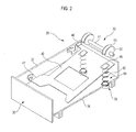
- Figure 2 is a schematic perspective view of a sheet feeding unit of the image forming apparatus of Figure 1
- Figure 3 is an exploded perspective view of a lifting device of the image forming apparatus of Figure 1
- Figure 4 is a bottom perspective view of a sheet feeding cassette of the image forming apparatus of Figure 1
- Figures 5 and 6 are perspective views illustrating an operation of the lifting device (as illustrated in Figure 3) of the image forming apparatus of Figure 1
- Figure 7 is a perspective view illustrating an operation of the sheet feeding unit (as illustrated in Figure 2) of the image forming apparatus of Figure 1.
- an image forming apparatus may include a body 10 which gives the image forming apparatus a particular shape, and a sheet feeding unit 20 to feed sheets of paper into the body 10.
- the body 10 is provided therein with a print unit (not illustrated) to print images on the sheets, a sheet discharge unit (not illustrated) to discharge the printed sheets to an outside, the sheet feeding unit 20, and a generator (not illustrated) to supply a driving force to the print unit, sheet discharge unit, etc.
- the print unit, sheet discharge unit and generator are similar to those of a conventional image forming apparatus, and thus a detailed description thereof will be omitted herein.
- the print unit may employ various printing methods such as laser printing, ink-jet printing, etc.
- the sheet feeding unit 20 includes a sheet feeding cassette 30 detachably coupled to an installation space 11 and defined at a lower portion of the body 10, a sheet lifting plate 40 positioned in the sheet feeding cassette 30 to stack sheets thereon, a pick-up device 50 to feed the sheets piece by piece from the sheet feeding plate 40, and a pair of lifting devices 60 to push the sheet lifting plate 40 toward the pick-up device 50.
- the sheet lifting plate 40 has a first end supported by the pair of lifting devices 60, which is positioned in the sheet feeding cassette 30 to lift an end of the sheets stacked on the sheet lifting plate 40 toward the pick-up device 50, and a second end hingedly coupled to a wall 32 of the sheet feeding cassette 30 by a hinge part 42. While the sheets are fed to the pick-up device 50, the first end of the sheet lifting plate 40 is pressed down by the pick-up device 50 and is simultaneously lifted by the lifting devices 60. Accordingly, the sheet lifting plate 40 is lifted to be closer to the pick-up device 50 after each subsequent sheet is picked-up by the pick-up device 50. In addition, the first end of the sheet lifting plate 40 is lifted at a predetermined angle based on a position of the hinge 42.
- the sheet lifting plate 40 is provided at the first end thereof with a pair of sheet separation pads 44 to smoothly separate an uppermost sheet from a plurality of sheets stacked on the sheet lifting plate 40.
- the first edge of the sheet lifting plate 40 is brought into contact with a sheet separation mechanism 46 formed at one side of the sheet feeding cassette 30.
- the sheet separation mechanism 46 abuts against an edge of the sheets stacked on the sheet lifting plate 40, and serves to allow the sheets to be fed one at a time without miss-feeding or double-feeding when the pick-up device 50 is operated.
- the pick-up device 50 includes a roller shaft 51 connected to a generator in the body 10, and a pair of pick-up rollers 52 coupled to the roller shaft 51.
- Each of the pick-up rollers 52 has a frictional member 53 attached thereon, and is positioned corresponding to each of the sheet separation pads 44 on the sheet lifting plate 40.
- the pick-up rollers 52 rotate along with the roller shaft 51, and serve to draw the sheets one at a time from the sheet feeding cassette 30 by pushing the sheets in a sheet-feeding direction.
- the pick-up rollers 52 are separated by a distance identical to a separation distance between the sheet separation pads 44 of the sheet lifting plate 40 in order to provide uniform compression of the lifting devices 60.
- Each of the lifting devices 60 acts as an adjustment unit to push the sheet lifting plate 40 toward the pick-up device 50 while varying a sheet feeding force of the pick-up device 50.
- the lifting device 60 includes a spring 65 to abut against a lower surface of the sheet lifting plate 40, and a spring adjustment mechanism 70 to adjust an installation height of the spring 65.
- Each of the springs 65 pushes the first end of the sheet lifting plate 40 toward the pick-up device 50 to force the sheets on the sheet lifting plate 40 to be brought into contact with the pick-up device 50.
- pressure generated when the pick-up rollers 52 are brought into contact with the sheets on the sheet lifting plate 40 varies depending on a magnitude of an elastic force of the spring 65, which pushes the sheet lifting plate 40 away from a bottom surface 34.
- the spring adjustment mechanism 70 adjusts the sheet feeding force of the pick-up device 50 by varying the elastic force of the spring 65 applied to the sheet lifting plate 40 through adjustment of an installation height of the corresponding spring 65.
- the spring adjustment mechanism 70 includes a guide member 71 positioned at a side of the bottom surface 34 of the sheet feeding cassette 30, and a spring lifting member 74 liftably coupled to the guide member 71 to support an end of the spring 65 coupled to the bottom surface 34.
- the guide member 71 has a ring shape and is open at upper and lower ends, and extends downward through the bottom surface 34 of the sheet feeding cassette 30.
- the guide member 71 has a pair of guide keys 72 protruding from an inner peripheral surface of the guide member 71 to face each other at different locations.
- the guide member 71 has a plurality of elongated positioning grooves 73 vertically formed in an inner peripheral surface of the guide member 71. The positioning grooves 73 secure the spring lifting member 74 at a specific height in combination with a plurality of positioning protrusions 77 of the spring lifting member 74 described below.
- the guide member 71 may be integral to the bottom surface 34 of the sheet feeding cassette 30, or may be a separate member secured to the bottom surface 23.
- the spring lifting member 74 has an outer peripheral surface corresponding to the inner peripheral surface of the guide member 71, and has a cylindrical shape, which is open at an upper end and closed at a lower end.
- a spiral groove 75 is formed around the outer peripheral surface of the spring lifting member 74, and can be fitted with the guide keys 72 of the guide member 71.
- a pair of key insertion grooves 76 is formed at an upper portion of the spring lifting member 74 to correspond to the pair of guide keys 72.
- the spring lifting member 74 has at least one positioning protrusion 77 formed at one side of the outer peripheral surface thereof.
- the positioning protrusion 77 is inserted into a corresponding positioning groove 73 among the plurality of positioning grooves 73 in the guide member 71 when the spring lifting member 74, which is screwed into the guide member 71, is rotated and reaches a specific height.
- a user may manipulate the spring lifting member 74 via a knob 78 provided at a lower portion of the spring lifting member 74.
- the lifting device 60 since the lifting device 60 is exposed to an outside through the bottom surface 34 of the sheet feeding cassette 30 as illustrated in Figure 4, the lifting device 60 can be manually manipulated by a user without dissembling or assembling thereof when drawing the sheet feeding cassette 30 from the body of the image forming apparatus.
- the knob 78 exposed below the sheet feeding cassette 30 in the clockwise or counterclockwise direction, the spring lifting member 74 is moved up or down along the guide member 71, raising and/or lowering the spring 65 towards and/or away from the pick-up device 50.
- the user can vary friction between the pick-up roller 52 and the sheets.
- the image forming apparatus can malfunction due to skewing of the sheets as well as non-smooth separation and feeding of the sheets due to a weak sheet feeding force of the pick-up rollers 52.
- the spring lifting member 74 may be raised by rotating the knob 78 of the spring lifting member 74. Rotating the knob 78 inadvertently raises the installation height of the spring 65 so that the elastic force of the spring 65 applied to the sheet lifting plate 40 increases. As a result, the sheet feeding force of the pick-up rollers 52 is increased so that such heavy sheets can be smoothly fed without skewing.
- the user can determine a suitable installation height of the spring lifting member 74 via vibration that occurs upon insertion of the positioning protrusion 77 of the spring lifting member 74 into the positioning grooves 73 of the guide member 71.
- the sheet separation mechanism 46 is positioned only at one side of the sheet feeding cassette 30 corresponding to one edge of the sheet lifting plate 40, one edge of the sheets contacting the sheet separation mechanism 46 may be subjected to higher resistance than any other edges of the sheets due to the sheet separation mechanism 46. Accordingly, since it is necessary to increase the sheet feeding force at the sheet separation mechanism 46 to allow the sheet to be smoothly fed without skewing, a corresponding spring lifting member 74 can be raised through manipulation of the spring adjustment mechanism 70 near the sheet separation mechanism 46. Then, the spring 65 closest to the sheet separation mechanism 46 can be raised higher than the other spring 65, which is farther from the sheet separation mechanism 46, thereby increasing the sheet feeding force of the pick-up roller 52 near the sheet separation mechanism 46. As a result, the sheets can be smoothly fed without skewing.
- a number of the pick-up rollers 52 or the lifting devices 60 may be one or may be three or more, and the sheet separation mechanism 46 may be positioned at either side of the sheet lifting plate 40.
- the lifting devices 60 is described herein as the adjustment unit to manually vary the sheet feeding force, the lifting devices may automatically vary the sheet feeding force by use of various driving mechanisms known by those skilled in the art.
- a sheet feeding unit can change a sheet feeding force of a pick-up device by varying an elastic force of a spring applied to a sheet lifting plate on which sheets are stacked.
- the sheet feeding unit enables the sheets to be smoothly fed to a print unit by increasing the sheet feeding force of the pick-up device through an increase in the elastic force of the spring applied to the sheet lifting plate.
- a number of lifting devices each having the spring to elastically support the sheet lifting plate may be provided corresponding to a number of pick-up rollers such that the spring of each lifting device can be adjusted in installation height, allowing the sheet feeding force of the pick-up rollers to be adjusted to permit smooth feeding of the sheets without skewing.
- the sheet feeding unit enables the sheet feeding force of the pick-up device to be easily varied through manual manipulation.
Landscapes
- Sheets, Magazines, And Separation Thereof (AREA)
Applications Claiming Priority (1)
| Application Number | Priority Date | Filing Date | Title |
|---|---|---|---|
| KR1020060102530A KR101351096B1 (ko) | 2006-10-20 | 2006-10-20 | 급지유닛 및 이를 갖는 화상형성장치 |
Publications (2)
| Publication Number | Publication Date |
|---|---|
| EP1914086A2 true EP1914086A2 (de) | 2008-04-23 |
| EP1914086A3 EP1914086A3 (de) | 2009-01-14 |
Family
ID=38962851
Family Applications (1)
| Application Number | Title | Priority Date | Filing Date |
|---|---|---|---|
| EP07116690A Withdrawn EP1914086A3 (de) | 2006-10-20 | 2007-09-18 | Papiereinzugseinheit |
Country Status (4)
| Country | Link |
|---|---|
| US (1) | US7673872B2 (de) |
| EP (1) | EP1914086A3 (de) |
| KR (1) | KR101351096B1 (de) |
| CN (1) | CN101164851A (de) |
Cited By (1)
| Publication number | Priority date | Publication date | Assignee | Title |
|---|---|---|---|---|
| CN109795901A (zh) * | 2017-11-17 | 2019-05-24 | 柯尼卡美能达办公系统研发(无锡)有限公司 | 纸张承载装置、纸盒、自动原稿搬送装置及图像形成装置 |
Families Citing this family (19)
| Publication number | Priority date | Publication date | Assignee | Title |
|---|---|---|---|---|
| KR101351096B1 (ko) * | 2006-10-20 | 2014-01-23 | 삼성전자주식회사 | 급지유닛 및 이를 갖는 화상형성장치 |
| JP2008207961A (ja) * | 2007-01-31 | 2008-09-11 | Ricoh Co Ltd | シート積載装置、シート搬送装置及び画像形成装置 |
| KR101150988B1 (ko) * | 2007-07-04 | 2012-06-01 | 삼성전자주식회사 | 급지유닛 및 이를 구비하는 화상형성장치 |
| US20100264579A1 (en) * | 2009-04-17 | 2010-10-21 | Kabushiki Kaisha Toshiba | Sheet carrying apparatus having sheet pressing mechanism, and sheet carrying method using sheet carrying mechanism |
| JP2011190029A (ja) * | 2010-03-15 | 2011-09-29 | Seiko Epson Corp | 媒体送り装置、記録装置 |
| JP2012188218A (ja) * | 2011-03-10 | 2012-10-04 | Ricoh Co Ltd | 給紙装置及び画像形成装置 |
| CN102408023A (zh) * | 2011-06-10 | 2012-04-11 | 刘安成 | 分纸斜 |
| CN102358079A (zh) * | 2011-10-31 | 2012-02-22 | 青岛海刚烫印设备制造有限公司 | 全自动送纸机 |
| US8695960B2 (en) * | 2011-12-20 | 2014-04-15 | Xerox Corporation | Automatic media loading and unloading system for producing dimensional documents |
| JP5979922B2 (ja) * | 2012-03-15 | 2016-08-31 | キヤノン株式会社 | シート給送装置及び画像形成装置 |
| JP5928204B2 (ja) | 2012-07-11 | 2016-06-01 | ブラザー工業株式会社 | シート搬送装置及び画像形成装置 |
| JP5843811B2 (ja) * | 2013-06-27 | 2016-01-13 | シャープ株式会社 | 給紙装置及び画像形成装置 |
| CN106185392A (zh) * | 2015-04-30 | 2016-12-07 | 北京鑫万佳科技发展有限公司 | 进票(纸)压力自动调节装置 |
| CN105109974A (zh) * | 2015-09-14 | 2015-12-02 | 天津市金利达纸业有限公司 | 一种定位送纸的装置 |
| CN105300717B (zh) * | 2015-11-06 | 2017-12-05 | 福建新大陆支付技术有限公司 | 一种热敏打印机出纸驱动能力的测试方法及装置 |
| KR101950180B1 (ko) * | 2016-06-01 | 2019-02-22 | 디에스글로벌(주) | 포토 프린터용 엔진 |
| JP7151271B2 (ja) * | 2018-08-24 | 2022-10-12 | セイコーエプソン株式会社 | シート載置装置及び印刷装置 |
| JP7171391B2 (ja) * | 2018-11-28 | 2022-11-15 | 日立チャネルソリューションズ株式会社 | 紙葉類仕分けシステム |
| CN119078380B (zh) * | 2024-10-11 | 2025-08-05 | 深圳长盛高精密五金有限公司 | 一种打印机防颤动器、打印机轴及防颤动方法 |
Family Cites Families (26)
| Publication number | Priority date | Publication date | Assignee | Title |
|---|---|---|---|---|
| JPS55119638A (en) * | 1979-03-06 | 1980-09-13 | Minolta Camera Co Ltd | Paper loading plate push-up-type cassette paper feeder |
| JP3272572B2 (ja) | 1995-07-10 | 2002-04-08 | キヤノン株式会社 | シート材給送装置および画像形成装置 |
| JP3375027B2 (ja) * | 1995-07-21 | 2003-02-10 | 株式会社リコー | 画像形成装置における給紙装置 |
| KR100258944B1 (ko) * | 1997-08-30 | 2000-06-15 | 윤종용 | 유니버설용지카세트 |
| JP2001026326A (ja) | 1999-07-14 | 2001-01-30 | Ricoh Co Ltd | 給紙分離装置 |
| TW500666B (en) * | 2000-03-03 | 2002-09-01 | Benq Corp | Paper feeding system with paper separation mechanism and paper stop mechanism |
| JP2002019977A (ja) * | 2000-07-03 | 2002-01-23 | Toshiba Tec Corp | 給紙装置 |
| US6585254B2 (en) * | 2000-07-14 | 2003-07-01 | Benq Corporation | Feeding device |
| DE60123712T2 (de) * | 2000-08-08 | 2007-08-16 | Ricoh Co., Ltd. | Blattzuführverfahren und Vorrichtung für eine Bilderzeugungsvorrichtung |
| JP3611781B2 (ja) * | 2000-08-29 | 2005-01-19 | シャープ株式会社 | 画像形成装置の給紙装置 |
| US20020066992A1 (en) * | 2000-12-01 | 2002-06-06 | Lim Kong Hock | Printer media pick apparatus |
| JP2002240966A (ja) | 2001-02-16 | 2002-08-28 | Ricoh Co Ltd | 給紙装置 |
| JP2003002456A (ja) | 2001-06-18 | 2003-01-08 | Funai Electric Co Ltd | 給紙機構 |
| US6575453B2 (en) * | 2001-11-06 | 2003-06-10 | Umax Data Systems Inc. | Pressure-adjustable mechanism for paper feeding roller of automatic paper feeder |
| KR100474440B1 (ko) * | 2002-09-13 | 2005-03-08 | 삼성전자주식회사 | 급지카세트 |
| JP2004307092A (ja) | 2003-04-03 | 2004-11-04 | Kyocera Mita Corp | シート供給装置 |
| JP4006366B2 (ja) * | 2003-07-02 | 2007-11-14 | キヤノン株式会社 | シート給送装置及び画像形成装置 |
| KR20050039061A (ko) | 2003-10-23 | 2005-04-29 | 삼성전자주식회사 | 개선된 스큐보정모듈을 갖는 화상형성장치 |
| US20050087922A1 (en) * | 2003-10-24 | 2005-04-28 | Erik Yi Zhang | Adjustable biasing device for sheet media feeder |
| TWI253391B (en) * | 2005-05-13 | 2006-04-21 | Benq Corp | A paper pick-up module of a printer of the like |
| KR20070087712A (ko) * | 2005-06-30 | 2007-08-29 | 삼성전자주식회사 | 급지 장치와 용지 픽업방법 및 이를 채용한 화상 형성 장치 |
| KR100692573B1 (ko) * | 2005-08-31 | 2007-03-13 | 삼성전자주식회사 | 화상형성기기의 급지장치 |
| KR100636246B1 (ko) * | 2005-09-06 | 2006-10-19 | 삼성전자주식회사 | 용지의 중송이 방지되는 급지장치 |
| US20070063423A1 (en) * | 2005-09-16 | 2007-03-22 | Kirby Alfred D | Media bed |
| JP4642667B2 (ja) * | 2006-01-26 | 2011-03-02 | キヤノン株式会社 | 画像形成装置 |
| KR101351096B1 (ko) * | 2006-10-20 | 2014-01-23 | 삼성전자주식회사 | 급지유닛 및 이를 갖는 화상형성장치 |
-
2006
- 2006-10-20 KR KR1020060102530A patent/KR101351096B1/ko not_active Expired - Fee Related
-
2007
- 2007-09-04 US US11/849,528 patent/US7673872B2/en active Active
- 2007-09-18 EP EP07116690A patent/EP1914086A3/de not_active Withdrawn
- 2007-09-19 CN CNA2007101534307A patent/CN101164851A/zh active Pending
Cited By (1)
| Publication number | Priority date | Publication date | Assignee | Title |
|---|---|---|---|---|
| CN109795901A (zh) * | 2017-11-17 | 2019-05-24 | 柯尼卡美能达办公系统研发(无锡)有限公司 | 纸张承载装置、纸盒、自动原稿搬送装置及图像形成装置 |
Also Published As
| Publication number | Publication date |
|---|---|
| US20080093792A1 (en) | 2008-04-24 |
| EP1914086A3 (de) | 2009-01-14 |
| CN101164851A (zh) | 2008-04-23 |
| US7673872B2 (en) | 2010-03-09 |
| KR20080035899A (ko) | 2008-04-24 |
| KR101351096B1 (ko) | 2014-01-23 |
Similar Documents
| Publication | Publication Date | Title |
|---|---|---|
| US7673872B2 (en) | Sheet feeding unit and image forming apparatus having the same | |
| KR100226091B1 (ko) | 수동식 기록용지 삽입기구 | |
| US7036815B2 (en) | Sheet material conveying apparatus, recording apparatus and recording system | |
| US6227533B1 (en) | Multi-functional sheet feeding apparatus | |
| KR102047904B1 (ko) | 인쇄매체공급장치 및 이를 갖는 화상형성장치 | |
| US7980554B2 (en) | Friction backup roller for media picking | |
| US7681878B2 (en) | Paper feeding unit and image forming apparatus having the same | |
| US7543814B2 (en) | Automatic paper feeding apparatus | |
| US8913946B2 (en) | Image forming apparatus | |
| JP2910021B2 (ja) | 画像形成装置 | |
| EP0908405B1 (de) | Papierzuführkassette mit einstellbarer Andrücksvorrichtung | |
| JP3346262B2 (ja) | 給紙装置 | |
| JPH03216424A (ja) | 給紙カセット | |
| KR200235600Y1 (ko) | 화상형성장치의 급지 장치 | |
| JP3634543B2 (ja) | 給紙装置 | |
| KR100318730B1 (ko) | 사무기기의 자동 급지장치 | |
| KR200180496Y1 (ko) | 화상형성기기의 용지 적재장치 | |
| KR200149599Y1 (ko) | 잉크-젯 프린터의 기록용지 자동급지장치 | |
| JP2005075492A (ja) | シ−ト材供給装置 | |
| JP2021178724A (ja) | シート収容装置、及びシート収容装置を備える画像形成装置 | |
| TWM252557U (en) | Automatic paper feeder | |
| JP2008201499A (ja) | シート材給送装置及び画像形成装置 | |
| JPH0940191A (ja) | 画像形成装置 | |
| JP2005075563A (ja) | 給紙装置 | |
| JP2001225963A (ja) | 電子写真記録装置 |
Legal Events
| Date | Code | Title | Description |
|---|---|---|---|
| PUAI | Public reference made under article 153(3) epc to a published international application that has entered the european phase |
Free format text: ORIGINAL CODE: 0009012 |
|
| AK | Designated contracting states |
Kind code of ref document: A2 Designated state(s): AT BE BG CH CY CZ DE DK EE ES FI FR GB GR HU IE IS IT LI LT LU LV MC MT NL PL PT RO SE SI SK TR |
|
| AX | Request for extension of the european patent |
Extension state: AL BA HR MK RS |
|
| PUAL | Search report despatched |
Free format text: ORIGINAL CODE: 0009013 |
|
| AK | Designated contracting states |
Kind code of ref document: A3 Designated state(s): AT BE BG CH CY CZ DE DK EE ES FI FR GB GR HU IE IS IT LI LT LU LV MC MT NL PL PT RO SE SI SK TR |
|
| AX | Request for extension of the european patent |
Extension state: AL BA HR MK RS |
|
| AKX | Designation fees paid | ||
| REG | Reference to a national code |
Ref country code: DE Ref legal event code: 8566 |
|
| STAA | Information on the status of an ep patent application or granted ep patent |
Free format text: STATUS: THE APPLICATION IS DEEMED TO BE WITHDRAWN |
|
| 18D | Application deemed to be withdrawn |
Effective date: 20090715 |