EP1916065A1 - Tête de pose - Google Patents
Tête de pose Download PDFInfo
- Publication number
- EP1916065A1 EP1916065A1 EP07020372A EP07020372A EP1916065A1 EP 1916065 A1 EP1916065 A1 EP 1916065A1 EP 07020372 A EP07020372 A EP 07020372A EP 07020372 A EP07020372 A EP 07020372A EP 1916065 A1 EP1916065 A1 EP 1916065A1
- Authority
- EP
- European Patent Office
- Prior art keywords
- setting head
- channel
- clip
- workpiece
- nuts
- Prior art date
- Legal status (The legal status is an assumption and is not a legal conclusion. Google has not performed a legal analysis and makes no representation as to the accuracy of the status listed.)
- Granted
Links
- 239000000463 material Substances 0.000 claims description 6
- 230000007704 transition Effects 0.000 claims description 2
- 238000012546 transfer Methods 0.000 description 6
- 229910000639 Spring steel Inorganic materials 0.000 description 1
- 229910000831 Steel Inorganic materials 0.000 description 1
- 230000003213 activating effect Effects 0.000 description 1
- 230000004323 axial length Effects 0.000 description 1
- 238000013461 design Methods 0.000 description 1
- 238000011161 development Methods 0.000 description 1
- 230000018109 developmental process Effects 0.000 description 1
- 238000006073 displacement reaction Methods 0.000 description 1
- 230000000694 effects Effects 0.000 description 1
- 238000002347 injection Methods 0.000 description 1
- 239000007924 injection Substances 0.000 description 1
- 238000003780 insertion Methods 0.000 description 1
- 230000037431 insertion Effects 0.000 description 1
- 239000012528 membrane Substances 0.000 description 1
- 239000002184 metal Substances 0.000 description 1
- 238000012986 modification Methods 0.000 description 1
- 230000004048 modification Effects 0.000 description 1
- 239000010959 steel Substances 0.000 description 1
- 238000012549 training Methods 0.000 description 1
Images


Classifications
-
- B—PERFORMING OPERATIONS; TRANSPORTING
- B25—HAND TOOLS; PORTABLE POWER-DRIVEN TOOLS; MANIPULATORS
- B25B—TOOLS OR BENCH DEVICES NOT OTHERWISE PROVIDED FOR, FOR FASTENING, CONNECTING, DISENGAGING OR HOLDING
- B25B31/00—Hand tools for applying fasteners
-
- Y—GENERAL TAGGING OF NEW TECHNOLOGICAL DEVELOPMENTS; GENERAL TAGGING OF CROSS-SECTIONAL TECHNOLOGIES SPANNING OVER SEVERAL SECTIONS OF THE IPC; TECHNICAL SUBJECTS COVERED BY FORMER USPC CROSS-REFERENCE ART COLLECTIONS [XRACs] AND DIGESTS
- Y10—TECHNICAL SUBJECTS COVERED BY FORMER USPC
- Y10T—TECHNICAL SUBJECTS COVERED BY FORMER US CLASSIFICATION
- Y10T29/00—Metal working
- Y10T29/53—Means to assemble or disassemble
- Y10T29/53478—Means to assemble or disassemble with magazine supply
-
- Y—GENERAL TAGGING OF NEW TECHNOLOGICAL DEVELOPMENTS; GENERAL TAGGING OF CROSS-SECTIONAL TECHNOLOGIES SPANNING OVER SEVERAL SECTIONS OF THE IPC; TECHNICAL SUBJECTS COVERED BY FORMER USPC CROSS-REFERENCE ART COLLECTIONS [XRACs] AND DIGESTS
- Y10—TECHNICAL SUBJECTS COVERED BY FORMER USPC
- Y10T—TECHNICAL SUBJECTS COVERED BY FORMER US CLASSIFICATION
- Y10T29/00—Metal working
- Y10T29/53—Means to assemble or disassemble
- Y10T29/53709—Overedge assembling means
- Y10T29/53783—Clip applier
Definitions
- the invention relates to a setting head according to the preamble of claim 1.
- the object of the invention is to show a setting head with which in a rational manner the setting or mounting so-called clip nuts on workpieces, in particular on workpieces made of a flat material is possible.
- a setting head according to the patent claim 1 is formed.
- the setting head can also be designed, among other things, in that a feed element which can be moved by a drive for pushing on the respective clip nuts located in the ready position by the Dispensing opening is provided on the workpiece, and or that the setting head with its discharge or mounting hole for mounting the Clip nuts can be positioned on the workpieces such that the respective, to be provided with a clip nut portion of the workpiece in the axial direction of the Canal extends, and or in that the discharge opening or mounting opening is formed by two opening sections, of which one opening section is an end opening or axial opening and another opening section is a lateral or radial opening of the channel, and or that a contact surface for the workpiece is formed laterally of the further opening section, and or that the at least one contact surface lies in a plane parallel or approximately parallel to the axis which the channel at least at the transition to Having discharge opening, and or in that the channel has a guide or channel extending in the channel longitudinal direction Abutment surface for the clip nuts forms, and that the at least
- clip nuts which consist essentially of a made of spring steel sheet clip 2 and a sleeve-like nut threaded part 3 with internal thread on this clip.
- the bow-shaped clip 2 forms two leg sections 4 and 5, which are connected to each other via a yoke section 6 and of which the leg section 4 is flat or substantially planar.
- the leg portion 5 is angled at its free end at 5.1 for ease of assembly.
- the leg 5 forms a section 5.2 which is in the region of the bend 5.1 with the rest of the leg 5 in conjunction, extending parallel or substantially parallel to the leg 4 in the direction of the yoke section 6.
- the nut threaded part 3 is provided or formed.
- the leg 4 is coaxially with the axis of the nut threaded piece 3, an opening for the passage of an engaging in the nut threaded part 3, but not shown screw provided.
- leg portion 5.1 and this section opposite free end 4.1 of the leg 4 form the front end 1.1 of the clip nut 1.
- the rear end 1.2 of the clip nut 1 is formed by the yoke portion 6 connecting the two leg sections 4 and 5.
- each clip nut 1 is located in the region of an opening 9 provided in the workpiece 8 ,
- the mounting of the clip nuts 1 is done by sliding using the setting head 10th
- the setting head 10 forms in a housing 11 a channel 12 for the clip nuts 1.
- the rectangular or square cross-section of this channel is adapted to the shape of the clip nuts 1 such that the clip nuts 1 in the channel 12 each have a predetermined orientation, namely such that the clip nuts 1 are each oriented with their front end 1.1 in a conveying direction A, in which these nuts are moved through the channel 12.
- the clip nuts 1 are arranged in the channel 12 so that they rest with their legs 4 on the underside 12.1 of the channel or are slidably moved in the conveying direction A through the channel 12 on the guide surface 12.1 formed by this underside.
- the channel 12 terminates at the setting head shown on the left in Fig. 10.1 or at a local discharge or mounting opening 13 and passes at the rear end 10.2 of the setting head 10 in a supply channel, which is formed in a flexible hose 14, which the setting head 10 connects with a supply unit, not shown, for the clip nut 1.
- the channel 12 is not only at its front end, but also radially or towards the bottom open, as shown in Figures 2 and 3 with the sections 13.1 and 13.2 of the discharge opening 13 is designated.
- Each contact surface 15 is an example pneumatically actuated clamping element 16 with respect to, so when mounting the respective clip nut 1, the workpiece 8 with its edge region between the contact surfaces 15 and the associated clamping elements 16 is received and clamped.
- the two contact surfaces 15 are in this case formed so that the side facing away from these plant surfaces of the workpiece 8 lies in a plane which is spaced from the plane of the guide surface 12.1 of the channel 12, by a measure which is equal to or slightly larger than that Material thickness of the leg 4, so that the respective clip nut 1 can be pushed with the leg 4 on the underside of the workpiece 8.
- a feed element is provided, in the illustrated embodiment in the form of a rocker 18, by a drive, namely in the illustrated embodiment by a pneumatic cylinder 19th and with a control arrangement, namely in the illustrated embodiment with a crank control 20 is movable such that at each full stroke of the pneumatic cylinder 19 initially located in a starting position outside the channel 12 feed rocker 18 with its swing head 18.1 through an opening 21 in the surface 12.1 entering the channel 12, the oscillating head 18.1 then moves in a working stroke in the channel 12 in the conveying direction A and thereby carries the respective located in the ready position 17 clip nut 1 and on the setting head 10 and at the local mounting opening 13 fixed work piece 8 postpones. After this working stroke, the swing head 18.1 moves out of the channel 12 through the opening 21 and returns outside the channel 12 in a return stroke to the starting position.
- the provision position 17 in the conveying direction A is preceded by a lock or change lock 22 is formed in the channel 12, after each stroke of the pneumatic cylinder 19 or after each pushing a clip nut 1 or even during this pushing for the advance or advancing another clip nut 1 on the supply position 17 opens and possibly further, on the supply hose 14 in the channel 12 already promoted or there magazine-like provided or magazinated clip nut 1 withholds.
- the change lock 22 is formed in the illustrated embodiment of two plungers 23 and 24 which are spaced by the length of a clip nut 1 in the transport direction A, ie in the axial direction of the channel 12 from each other, and in synchronism with the movement of the feed pawl 18 are moved in opposite directions, and although in such a way that whenever a plunger 23 or 24 is moved radially out of the channel 12 and thus releases the channel, the other plunger 24 and 23 is moved into the channel 12 and thus the channel 12 blocks.
- rocker-like lever 25 which is about an axis perpendicular to the longitudinal extent of the channel 12th and is pivotable perpendicular to a plane in which the axes of the plungers 23 and 24 are arranged.
- the rocker 25 or provided on this rocker guide member cooperates with a control cam 26 which is formed on a carriage 27 which is guided in the interior of the housing 11 in the direction of the axis of the channel 12 back and forth, by means of rollers 28 on an outer surface of the channel 12 forming hollow profile 29.
- the carriage 27 is further drivingly also connected to the pneumatic cylinder 19.
- the operation of the setting head 10 can be described as follows:
- the setting head is fixed with its discharge opening 13 at the relevant edge region of the workpiece 8 by clamping between the contact surfaces 15 and the clamping elements 16.
- this clip nut is pushed out of the ready position 17 onto the workpiece 8 with the feed rocker 18 or the head 18.1.
- another clip nut 10 passes from the sluice 22 to the ready position 17.
- the advancing movement of the clip nuts 1 within the channel 12 takes place, for example. by conveying air.
- the setting head 10 via the supply hose 14, by injection, i. by conveying air constantly clip nuts 1 either individually or as a pulp fed so that a sufficiently large number of Klippmutern 1 in the channel in front of the lock 22 are.
- the operation of the setting head 10 is monitored and in particular to the effect that before each stroke at the ready position 17 a clip nut 1 is located.
- the sensor then monitors and controls the provision of the setting head 10 with clip nuts 1 from the supply unit via the supply hose 14.
- the clip nuts 1 are stored in this setting head or in the guide 12 during operation of the setting head 10 be in each working stroke only the first of the collated clip nuts 1 is forwarded to the staging position 17 by the change lock 22.
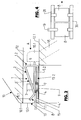
- FIG. 4 shows, in a very schematic representation, the transfer bars, designated 30 and 31, of a stepping tool.
- a setting head 10 is provided, at which, for example, during the transfer of the workpiece 8 between two stages of the tool and thus e.g. to reduce cycle times the mounting of the respective clip nut 1 takes place.
- the setting head 10 can also take over the function of the provided on the relevant area of the transfer bar clamping or clamping device for the workpiece 8. Analogously to FIG. 4, it is furthermore possible to provide setting heads 10 on so-called lifting beams of following tools in order to also insert clip nuts 1 into the components 8 produced with such a tool.
- FIG. 6 shows a simplified representation of the front end 10a.1 of a setting head 10a, which basically differs from the setting head 10 only in that instead of one, the respective clip nut from the ready position 17a on the workpiece 8 aufschiebenden feed element an investment or support element 32 is provided, against which the clip nut 1 located in the ready position 17 a rests with its rear end 1.2 when pushed onto the workpiece 8.
- the sliding of the clip nut 1 takes place by a relative movement between the workpiece 8 and the setting head 10, for example, by a corresponding advancing movement of the setting head 10a in such a way that while the workpiece 8 is pushed with its edge region on the clip nut 1.
- the abutment element 32 is part of a lever 33, which by a drive synchronously with the supply of the clip nuts 1 or synchronously with the also in this embodiment in the feed direction (arrow A) of the clip nuts 1 before the provision position 17a sluice or Change lock 22 ( Figure 1) is pivoted (double arrow B) that when feeding a clip nut to the provision position, the abutment element 32 is located outside of the channel 12a.
- controlled latch means 34 By means of controlled latch means 34, the respective clip nut 1, which is conveyed to the provision position 17a by conveying air, is stopped at this position.
- This training may also be useful in particular when several clip nuts 1 are to be mounted on a workpiece 8 with several setting heads 10 at the same time.
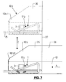
- FIG. 7 shows, in a very simplified schematic representation as a further embodiment, a setting head 10b, which differs from the setting head 10a in that the setting head 10b is designed in two parts, consisting of a front part 35, the front 10b.1 and the provisioning position 17b.1 forms, as well as from a rear 36, which also has the lock or exchange lock 22.
- the front part 35 is displaceably guided on a guide 37 fastened on both sides to the rear part by a drive not shown, corresponding to the double arrow C in an axial direction perpendicular to the conveying direction A from a loading position in which the front part 35 is the continuation of the rearward Part 36 forms, in a working position, which is indicated in the figure 7 with broken lines and in which the front part 35 is spaced from the rear portion 36, that is located laterally or above the rear portion 36.
- the mode of operation of the setting head 10b is essentially such that in each case a clip nut 1 is introduced into the loading position of the part 35 into the provision position 17b there.
- the part 35 is moved in the direction indicated in Figure 7 with broken lines working position in which the guide 37 forms a support for the rear end 1.2 of the respective clip nut 1, so that in turn by relative movement between the workpiece 8 and the setting head 10b can be pushed onto the workpiece.
- the setting head 10b has the advantage that its effective length in the working position is determined only by the axial length of the relatively short part 35, so that with the setting head 10b and the sliding of clip nuts 1 not only at the edge region of a workpiece 8, but for example the edge region, for example, the closed edge region of a recess formed within the workpiece 8 is possible.
Landscapes
- Engineering & Computer Science (AREA)
- Mechanical Engineering (AREA)
- Automatic Assembly (AREA)
- Jigs For Machine Tools (AREA)
Applications Claiming Priority (3)
| Application Number | Priority Date | Filing Date | Title |
|---|---|---|---|
| DE102006051182 | 2006-10-29 | ||
| DE102007022976 | 2007-05-15 | ||
| DE102007032953A DE102007032953A1 (de) | 2006-10-29 | 2007-07-14 | Setzkopf |
Publications (2)
| Publication Number | Publication Date |
|---|---|
| EP1916065A1 true EP1916065A1 (fr) | 2008-04-30 |
| EP1916065B1 EP1916065B1 (fr) | 2011-07-13 |
Family
ID=38917824
Family Applications (1)
| Application Number | Title | Priority Date | Filing Date |
|---|---|---|---|
| EP07020372A Not-in-force EP1916065B1 (fr) | 2006-10-29 | 2007-10-18 | Tête de pose |
Country Status (4)
| Country | Link |
|---|---|
| US (1) | US7966719B2 (fr) |
| EP (1) | EP1916065B1 (fr) |
| CA (1) | CA2608649C (fr) |
| DE (1) | DE102007032953A1 (fr) |
Cited By (1)
| Publication number | Priority date | Publication date | Assignee | Title |
|---|---|---|---|---|
| FR3002089A1 (fr) * | 2013-02-13 | 2014-08-15 | Sam Outil | Dispositif de pose d'une agrafe de connexion electrique |
Families Citing this family (2)
| Publication number | Priority date | Publication date | Assignee | Title |
|---|---|---|---|---|
| US8006374B1 (en) * | 2008-06-24 | 2011-08-30 | Zangari Salvator G | Paperclip fastening apparatus |
| CN117465973B (zh) * | 2023-12-27 | 2024-03-15 | 常州长盛机械有限公司 | 挖掘机用金属横梁切割成型用输送设备 |
Citations (5)
| Publication number | Priority date | Publication date | Assignee | Title |
|---|---|---|---|---|
| US3702494A (en) | 1971-05-06 | 1972-11-14 | Microdt Inc | Fastener applying tool |
| EP0157295A2 (fr) * | 1984-04-03 | 1985-10-09 | Springfix Befestigungstechnik Gmbh | Dispositif de mise en place de bagues de sécurité axiales |
| US4625380A (en) | 1985-03-12 | 1986-12-02 | Everhard Paul R | Clip insert tool |
| EP0224746A1 (fr) | 1985-12-04 | 1987-06-10 | Firma A. Raymond | Ecrou en tôle formant pince |
| EP0390062A2 (fr) * | 1989-03-31 | 1990-10-03 | A. Raymond GmbH & Co. KG | Ecrou en tôle formant une pince pour montage automatique |
Family Cites Families (4)
| Publication number | Priority date | Publication date | Assignee | Title |
|---|---|---|---|---|
| US3971116A (en) * | 1975-05-05 | 1976-07-27 | Multifastener Corporation | Fastener installation head |
| US4242793A (en) * | 1979-05-25 | 1981-01-06 | Multifastener Corporation | Nut guide for installation head |
| DE20101062U1 (de) * | 2001-01-19 | 2001-06-28 | Schmidt, Heiko, Dipl.-Ing., 93047 Regensburg | Vorrichtung zum Einbringen von Funktionsteilen, insbesondere Verbindungselementen in Bauteile sowie Versorgungseinheit für eine solche Vorrichtung |
| US6578258B1 (en) * | 2002-05-24 | 2003-06-17 | Whitesell Of Michigan Inc. | Pierce nut installation head |
-
2007
- 2007-07-14 DE DE102007032953A patent/DE102007032953A1/de not_active Ceased
- 2007-10-18 EP EP07020372A patent/EP1916065B1/fr not_active Not-in-force
- 2007-10-26 CA CA2608649A patent/CA2608649C/fr not_active Expired - Fee Related
- 2007-10-29 US US11/976,915 patent/US7966719B2/en not_active Expired - Fee Related
Patent Citations (5)
| Publication number | Priority date | Publication date | Assignee | Title |
|---|---|---|---|---|
| US3702494A (en) | 1971-05-06 | 1972-11-14 | Microdt Inc | Fastener applying tool |
| EP0157295A2 (fr) * | 1984-04-03 | 1985-10-09 | Springfix Befestigungstechnik Gmbh | Dispositif de mise en place de bagues de sécurité axiales |
| US4625380A (en) | 1985-03-12 | 1986-12-02 | Everhard Paul R | Clip insert tool |
| EP0224746A1 (fr) | 1985-12-04 | 1987-06-10 | Firma A. Raymond | Ecrou en tôle formant pince |
| EP0390062A2 (fr) * | 1989-03-31 | 1990-10-03 | A. Raymond GmbH & Co. KG | Ecrou en tôle formant une pince pour montage automatique |
Cited By (1)
| Publication number | Priority date | Publication date | Assignee | Title |
|---|---|---|---|---|
| FR3002089A1 (fr) * | 2013-02-13 | 2014-08-15 | Sam Outil | Dispositif de pose d'une agrafe de connexion electrique |
Also Published As
| Publication number | Publication date |
|---|---|
| CA2608649C (fr) | 2011-01-04 |
| EP1916065B1 (fr) | 2011-07-13 |
| US20080127483A1 (en) | 2008-06-05 |
| US7966719B2 (en) | 2011-06-28 |
| DE102007032953A1 (de) | 2008-04-30 |
| CA2608649A1 (fr) | 2008-04-29 |
Similar Documents
| Publication | Publication Date | Title |
|---|---|---|
| DE69829592T2 (de) | Pneumatische Nagelmaschine für Feinarbeiten | |
| DE4415973C2 (de) | Vorrichtung zur Verwendung in einer Presse zum Zuführen von Verbindungselementen und zu deren Befestigung in Werkstücken durch Verpressen | |
| EP3242760B1 (fr) | Dispositif et procédé pour poser un élément de liaison sur une pièce | |
| DE102014220194A1 (de) | Zuführeinheit | |
| WO2009097837A1 (fr) | Dispositif de traitement de clips, de vis, de boulons, d'écrous ou d'éléments d'assemblage analogues | |
| EP1916065B1 (fr) | Tête de pose | |
| DE3004549A1 (de) | Einrichtung zum diskontinuierlichen, schrittweisen zufuehren von einem oder mehreren laenglichen werkstuecken an eine oder mehrere bearbeitungsmaschinen | |
| DE29902398U1 (de) | Vorrichtung zum Einbringen von Verbindungselementen in Werkstücke | |
| DE10213850C1 (de) | Matritzenseitige Auswerfvorrichtung für Werkstücke bei Ein- und Mehrstufenpressen | |
| DE4422708B4 (de) | Vorrichtung zur Verwendung in einer Presse zum Zuführen von Verbindungselementen und deren Befestigung in Werkstücken durch Verpressen | |
| DE10208935B4 (de) | Vorrichtung zum Einbringen und Verankern von Verbindungselementen in Werkstücke | |
| WO1995011770A1 (fr) | Dispositif s'utilisant dans une presse pour acheminer des elements d'assemblage et pour les fixer par pression dans des pieces | |
| DE69513464T2 (de) | Vorrichtung für die Befestigung von selbststanzenden Muttern auf einem Blech | |
| DE10359879A1 (de) | Hydraulische Bearbeitungszange | |
| EP0407658B1 (fr) | Dispositif de serrage et de refoulement ou de serrage et de martelage pour le serrage temporaire de pièces en fils métalliques resp. pour le travail de telles pièces | |
| EP3302843B1 (fr) | Outil de pliage pour presse plieuse | |
| EP3956084B1 (fr) | Tête de pose, presse pour tôle ou dispositif de pose pourvu de cette tête de pose et procédé d'assemblage d'un élément d'assemblage avec ladite tête de pose | |
| DE2443376A1 (de) | Presse, insbesondere rahmenpresse | |
| DE4340642A1 (de) | Vorrichtung zur Verwendung in einer Presse zum Zuführen von Verbindungselementen und zu deren Befestigung in Werkstücken durch Verpressen | |
| DE10007255A1 (de) | Einrichtung zum stempelseitigen Auswerfen von Werkstücken für Ein- oder Mehrstufenpressen | |
| EP1984132B1 (fr) | Pince d'usinage hydraulique | |
| DE4343154C2 (de) | Vorrichtung zur Verwendung in einer Presse zum Zuführen von Verbindungselementen und deren Befestigung in Werkstücken durch Verpressen | |
| DE3020545A1 (de) | Vorrichtung zum einbringen von loechern in einem bauelement | |
| DE102004002844B3 (de) | Einpressvorrichtung zur Bearbeitung vorgeformter Bauteile | |
| DE102004007265B4 (de) | Bearbeitungszange |
Legal Events
| Date | Code | Title | Description |
|---|---|---|---|
| PUAI | Public reference made under article 153(3) epc to a published international application that has entered the european phase |
Free format text: ORIGINAL CODE: 0009012 |
|
| AK | Designated contracting states |
Kind code of ref document: A1 Designated state(s): AT BE BG CH CY CZ DE DK EE ES FI FR GB GR HU IE IS IT LI LT LU LV MC MT NL PL PT RO SE SI SK TR |
|
| AX | Request for extension of the european patent |
Extension state: AL BA HR MK RS |
|
| 17P | Request for examination filed |
Effective date: 20081001 |
|
| 17Q | First examination report despatched |
Effective date: 20081110 |
|
| AKX | Designation fees paid |
Designated state(s): DE ES FR IT |
|
| GRAP | Despatch of communication of intention to grant a patent |
Free format text: ORIGINAL CODE: EPIDOSNIGR1 |
|
| GRAS | Grant fee paid |
Free format text: ORIGINAL CODE: EPIDOSNIGR3 |
|
| GRAA | (expected) grant |
Free format text: ORIGINAL CODE: 0009210 |
|
| AK | Designated contracting states |
Kind code of ref document: B1 Designated state(s): DE ES FR IT |
|
| REG | Reference to a national code |
Ref country code: DE Ref legal event code: R096 Ref document number: 502007007645 Country of ref document: DE Effective date: 20110908 |
|
| REG | Reference to a national code |
Ref country code: ES Ref legal event code: FG2A Ref document number: 2369726 Country of ref document: ES Kind code of ref document: T3 Effective date: 20111205 |
|
| PLBE | No opposition filed within time limit |
Free format text: ORIGINAL CODE: 0009261 |
|
| STAA | Information on the status of an ep patent application or granted ep patent |
Free format text: STATUS: NO OPPOSITION FILED WITHIN TIME LIMIT |
|
| 26N | No opposition filed |
Effective date: 20120416 |
|
| REG | Reference to a national code |
Ref country code: DE Ref legal event code: R097 Ref document number: 502007007645 Country of ref document: DE Effective date: 20120416 |
|
| REG | Reference to a national code |
Ref country code: FR Ref legal event code: PLFP Year of fee payment: 9 |
|
| REG | Reference to a national code |
Ref country code: FR Ref legal event code: PLFP Year of fee payment: 10 |
|
| REG | Reference to a national code |
Ref country code: FR Ref legal event code: PLFP Year of fee payment: 11 |
|
| REG | Reference to a national code |
Ref country code: FR Ref legal event code: PLFP Year of fee payment: 12 |
|
| PGFP | Annual fee paid to national office [announced via postgrant information from national office to epo] |
Ref country code: DE Payment date: 20191030 Year of fee payment: 13 |
|
| PGFP | Annual fee paid to national office [announced via postgrant information from national office to epo] |
Ref country code: FR Payment date: 20191028 Year of fee payment: 13 Ref country code: IT Payment date: 20191028 Year of fee payment: 13 Ref country code: ES Payment date: 20191122 Year of fee payment: 13 |
|
| REG | Reference to a national code |
Ref country code: DE Ref legal event code: R119 Ref document number: 502007007645 Country of ref document: DE |
|
| PG25 | Lapsed in a contracting state [announced via postgrant information from national office to epo] |
Ref country code: DE Free format text: LAPSE BECAUSE OF NON-PAYMENT OF DUE FEES Effective date: 20210501 Ref country code: FR Free format text: LAPSE BECAUSE OF NON-PAYMENT OF DUE FEES Effective date: 20201031 |
|
| PG25 | Lapsed in a contracting state [announced via postgrant information from national office to epo] |
Ref country code: IT Free format text: LAPSE BECAUSE OF NON-PAYMENT OF DUE FEES Effective date: 20201018 |
|
| REG | Reference to a national code |
Ref country code: ES Ref legal event code: FD2A Effective date: 20220128 |
|
| PG25 | Lapsed in a contracting state [announced via postgrant information from national office to epo] |
Ref country code: ES Free format text: LAPSE BECAUSE OF NON-PAYMENT OF DUE FEES Effective date: 20201019 |