EP1923559A1 - A method of controlling a piezoelectric actuator - Google Patents
A method of controlling a piezoelectric actuator Download PDFInfo
- Publication number
- EP1923559A1 EP1923559A1 EP06255815A EP06255815A EP1923559A1 EP 1923559 A1 EP1923559 A1 EP 1923559A1 EP 06255815 A EP06255815 A EP 06255815A EP 06255815 A EP06255815 A EP 06255815A EP 1923559 A1 EP1923559 A1 EP 1923559A1
- Authority
- EP
- European Patent Office
- Prior art keywords
- stack
- current
- charge
- during
- corrective action
- Prior art date
- Legal status (The legal status is an assumption and is not a legal conclusion. Google has not performed a legal analysis and makes no representation as to the accuracy of the status listed.)
- Granted
Links
Images



Classifications
-
- F—MECHANICAL ENGINEERING; LIGHTING; HEATING; WEAPONS; BLASTING
- F02—COMBUSTION ENGINES; HOT-GAS OR COMBUSTION-PRODUCT ENGINE PLANTS
- F02D—CONTROLLING COMBUSTION ENGINES
- F02D41/00—Electrical control of supply of combustible mixture or its constituents
- F02D41/20—Output circuits, e.g. for controlling currents in command coils
- F02D41/2096—Output circuits, e.g. for controlling currents in command coils for controlling piezoelectric injectors
-
- F—MECHANICAL ENGINEERING; LIGHTING; HEATING; WEAPONS; BLASTING
- F02—COMBUSTION ENGINES; HOT-GAS OR COMBUSTION-PRODUCT ENGINE PLANTS
- F02D—CONTROLLING COMBUSTION ENGINES
- F02D41/00—Electrical control of supply of combustible mixture or its constituents
- F02D41/24—Electrical control of supply of combustible mixture or its constituents characterised by the use of digital means
- F02D41/2406—Electrical control of supply of combustible mixture or its constituents characterised by the use of digital means using essentially read only memories
- F02D41/2425—Particular ways of programming the data
- F02D41/2429—Methods of calibrating or learning
- F02D41/2451—Methods of calibrating or learning characterised by what is learned or calibrated
- F02D41/2464—Characteristics of actuators
- F02D41/2467—Characteristics of actuators for injectors
-
- F—MECHANICAL ENGINEERING; LIGHTING; HEATING; WEAPONS; BLASTING
- F02—COMBUSTION ENGINES; HOT-GAS OR COMBUSTION-PRODUCT ENGINE PLANTS
- F02D—CONTROLLING COMBUSTION ENGINES
- F02D41/00—Electrical control of supply of combustible mixture or its constituents
- F02D41/20—Output circuits, e.g. for controlling currents in command coils
- F02D2041/202—Output circuits, e.g. for controlling currents in command coils characterised by the control of the circuit
- F02D2041/2051—Output circuits, e.g. for controlling currents in command coils characterised by the control of the circuit using voltage control
-
- F—MECHANICAL ENGINEERING; LIGHTING; HEATING; WEAPONS; BLASTING
- F02—COMBUSTION ENGINES; HOT-GAS OR COMBUSTION-PRODUCT ENGINE PLANTS
- F02D—CONTROLLING COMBUSTION ENGINES
- F02D41/00—Electrical control of supply of combustible mixture or its constituents
- F02D41/02—Circuit arrangements for generating control signals
- F02D41/04—Introducing corrections for particular operating conditions
- F02D41/06—Introducing corrections for particular operating conditions for engine starting or warming up
- F02D41/062—Introducing corrections for particular operating conditions for engine starting or warming up for starting
- F02D41/064—Introducing corrections for particular operating conditions for engine starting or warming up for starting at cold start
Definitions
- the invention relates to a method of controlling a piezoelectric actuator for use in a fuel injector. More specifically, the invention relates to a method of operating a piezoelectrically actuated fuel injector in order to improve fuel volume delivery.
- a piezoelectric injector typically includes a piezoelectric actuator that is operable to control an injection nozzle.
- the injection nozzle houses an injector valve needle which is movable relative to a valve needle seat under the control of the actuator.
- a hydraulic amplifier is situated between the actuator and the needle such that axial movement of the actuator causes an amplified axial movement of the needle.
- the valve needle is either caused to disengage the valve seat, in which case fuel is delivered into the associated engine cylinder through a set of outlets provided in a tip of the nozzle, or is caused to engage the valve seat, in which case fuel delivery is prevented.
- the amount of charge is varied causing the valve needle to move between closed and open positions.
- the amount of charge applied to and removed from the piezoelectric actuator can be controlled in two ways.
- a current is driven into or out of the piezoelectric actuator for a required time.
- a current is driven into or out of the piezoelectric actuator until the voltage across the piezoelectric actuator reaches a required level. Regardless of how the piezoelectric actuator is controlled, the voltage across the piezoelectric actuator changes as the level of charge on the piezoelectric actuator varies and vice versa.
- injecting a larger than desired volume of fuel when the demand on the engine is already high could result in the engine temperature and fuel pressure exceeding predetermined safety limits: exceeding such limits could result in irreparable damage to the engine.
- a method for controlling the displacement of a stack of a piezoelectric actuator for use in a fuel injector in order to control fuel volume delivery comprising causing a varying current to be driven into or out of the stack to charge or discharge the stack, respectively, during an opening phase, wherein the opening phase comprises at least a primary phase, measuring a parameter during the opening phase, comparing the measured parameter with a predetermined threshold value, and taking corrective action to adjust the fuel volume delivery, during a subsequent injection, depending on the result of the comparison.
- the present invention advantageously improves the control of a piezoelectric actuator and alleviates the problems associated with inconsistent fuel volume delivery, preventing damage to the engine.
- the parameter is voltage and the method comprises measuring a voltage across the stack at the end of the primary phase, comparing the voltage across the stack with the predetermined threshold value, and taking corrective action to adjust the fuel volume delivery, during the subsequent injection, if the measured voltage across the stack is less than the predetermined threshold value.
- the parameter is chop frequency and the method comprises measuring a minimum chop frequency of the varying current during the opening phase, comparing the minimum chop frequency with the predetermined threshold value, and taking corrective action to adjust the fuel volume delivery, during the subsequent injection, if the measured minimum chop frequency is less than the predetermined threshold value.
- the parameter is chop period and the method comprises measuring a maximum chop period during the opening phase, comparing the maximum chop period with the predetermined threshold value, and taking corrective action to adjust the fuel volume delivery, during the subsequent injection, if the measured maximum chop period is more than the predetermined threshold value.
- the method comprises varying the current between an upper current threshold level and a lower current threshold level and determining the upper and lower current thresholds from a current set-point level which is selectable such that the mean value of the varying current driven into or out of the stack for a time is intended to equal a desired amount of charge to be applied to or removed from the stack.
- the corrective action may comprise adjusting the current set-point level in order to adjust the amount of charge which is applied to or removed from the stack.
- the corrective action may comprise adjusting the time for which the varying current is driven into or out of the stack in order to adjust the amount of charge which is applied to or removed from the stack.
- the method may further comprise determining an injector on time comprising the opening phase and a dwell phase, wherein the corrective action includes adjusting the injector on time in order to adjust the fuel volume delivery.
- the corrective action may comprise adjusting the current set-point level in order to adjust the amount of charge which is applied to or removed from the stack.
- the comparing step further comprises comparing at least one of engine load, engine temperature, and fuel pressure with its respective threshold level, wherein corrective action is taken when at least one of engine load, engine temperature, and fuel pressure is above its threshold level.
- the corrective action may be taken in order to prevent more than a desired fuel volume delivery being delivered.
- the corrective action may be taken in order to prevent less than a desired fuel volume delivery being delivered.
- the invention also relates to a controller for a fuel injector for implementing a method in accordance with the first aspect of the invention.
- the invention extends to a computer program product comprising at least one computer program software portion which, when executed in an executing environment, is operable to implement the method of the present invention, and a data storage medium having the or each computer software portion stored thereon.
- the invention also extends to a microcomputer provided with the data storage medium.
- rate of charge means the rate of change in current over time, which may be as a result of either charging or discharging the piezoelectric actuator.
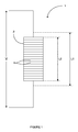
- Figure 1 shows a schematic diagram of a piezoelectric actuator 1 including a stack 2 of capacitive piezoelectric elements 4, which are effectively connected in parallel.
- the actuator is of the type suitable for use in a fuel injector of the type described in EP 1174615 having a valve needle which is operable by means of the actuator.
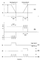
- Figure 2(a) shows a typical graph of charge versus time for an actuator 1, which is driven from a closed non-injecting position to an open injecting position (i.e. an opening/discharging phase 6) and back again to the non-injecting position (i.e. a closing/charging phase 8).
- the opening phase 6 the charge changes from a first charge level Q1 to a second charge level Q2 over a time t open .
- the difference between Q1 and Q2 equals a change in charge ⁇ Q, which corresponds to the length of the stack 2 changing from a relatively long length L 1 to a relatively short length L2, as shown in Figure 1.
- the change in length of the stack 2 directly controls movement of an injector valve needle, and hence controls fuel delivery.
- the aforementioned method of controlling a piezoelectric actuator 1 is referred to as a charge control method. It is possible to operate an actuator using this method by determining how much charge is to be applied to/removed from the stack, and applying/removing an appropriate current to/from the stack 2 for the required time in accordance with the equation above.
- a varying current is used for charging and discharging the stack.
- the mean value of the current is known, and will be referred to as the current set point or level.
- Figure 2(b) also shows a typical graph of current versus time, for a varying current (the mean value/set point is shown by the dashed line), which is applied to the stack 2 in order to achieve the charge waveform shown in Figure 2(a).
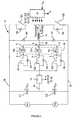
- the drive circuit in Figure 3 is arranged to drive an injector bank 16 comprising first, second and third injectors 16a, 16b, 16c respectively, each of which includes an actuator as shown in Figure 1.
- the drive circuit includes a first voltage source V s1 , a second voltage source V S2 , first and second energy storage capacitors C1 and C2, a current flow sensing and control means 14, injector select switches S1 S2 S3 each of which is associated with a respective one of the injectors 16a, 16b, 16c, an inductor 18, a charge switch Q1, a discharge switch Q2, and a microprocessor 20.
- Each of the injector select switches S1, S2, S3 typically takes the form of an insulated gate bipolar transistor (IGBT) having a gate coupled to a gate drive which is powered at a bias supply input.
- the charge and discharge switches Q1, Q2 may take the form of an n-channel IGBT having a gate controlling current flow from the collector to the emitter.
- the first voltage supply V S1 is connected across a top voltage rail 28, which is at a top voltage level V top , and a middle voltage rail known as a bi-directional middle current path 30, which is at a stack voltage level V stack .
- the second voltage supply V S2 is connected across the middle voltage rail 30 and a bottom voltage rail 32 which is at a bottom voltage level V bottom .
- the first energy storage capacitor C 1 is connected between the top voltage rail 28 and the middle current path 30, and the second storage capacitor C2 is connected between the middle current path 30 and bottom voltage rail 32.
- the current flow sensing and control means 14 is connected in the middle current path 30, between a connection point between the first and second storage capacitors C1, C2 and the injector bank 16.
- the injectors 16a, 16b, 16c are connected in parallel, each injector 16a, 16b, 16c being connected in a different parallel branch and each branch including an injector select switch S1, S2, S3, which has a diode D3, D4, D5 connected across it.
- the injectors 16a, 16b, 16c are mounted remotely from the drive circuit 10, and connections x and y are provided, to the drive circuit 10, through appropriate connecting leads.
- each of the injectors 16a, 16b, 16c are connected to their respective select switches S1, S2, S3.
- the positive terminals of the injectors 16a, 16b, 16c are connected together, and coupled in series to the inductor 18.
- a diode D6 is provided between the middle current path 30 on the injector side of the inductor 18 and the top voltage rail 28, and another diode D7 is provided between the bottom voltage rail 32 and the middle current path 30, again, on the injector side of the inductor 18.
- the diode D6 provides a 'voltage clamping effect' for a selected injector 16a, 16b, 16c at the end of its charge phase 8, and prevents the injector 16a, 16b, 16c from being driven to voltages higher than V C1 .
- the diode D7 provides a recirculation path for current flow during the discharge phase 6 of operation, as described in further detail below.
- the charge switch Q1 is connected between the non-injector side of the inductor 18 and the top voltage rail 28, and a diode D8 is connected in parallel across it.
- the discharge switch Q2 is connected between the bottom voltage rail 32 and the non-injector side of the inductor 18, and similarly, a diode D9 is connected in parallel across it.
- the output I s of the current flow sensing and control means 14 is fed into an input of the microprocessor 20, which provides control signals for the current flow sensing and control means 14, the injector select switches S1, S2, S3, the charge switch Q1, and the discharge switch Q2.
- the control signals for the discharge and charge switches Q2, Q1 are referred to as a discharge enable signal 34 and a charge enable signal 36, respectively.
- the current is caused to vary between an upper current threshold level I 1 and a lower current threshold level I 2 under the control of the current sensing and control means 14 in conjunction with the microprocessor 20.
- the current sensing and control means 14 monitors the current flow and generates a chopped signal 38 ( Figure 2(e)) on the basis of the 'sensed' current Is. This will be described in further detail below.
- the chopped signal 38 is combined with a discharge enable signal 34 ( Figure 2(c)) through a logical AND gate, and the resultant signal is applied to the discharge switch Q2.
- the chopped signal 38 is also combined with a charge enable signal 36 ( Figure 2(d) through a logical AND gate, and that resultant signal is applied to the charge switch Q1.
- the discharge switch Q2 opens and closes to effectively generate the varying current signal in the discharge phase 6. In the charge phase 8, it is the charge switch Q1 that controls generation of the varying current.
- Look-up tables within the microprocessor's memory store values for a primary opening current set point PO, a primary opening time POT, and a primary closing current set point PC.
- the microprocessor 20 selects the value of primary opening current set point PO, primary opening time POT, and primary closing time depending on stack pressure, stack temperature, and a demanded injector on time TON (which is determined from the fuel demand and is also a function of the fuel rail pressure).
- the drive circuit 10, and hence fuel delivery, are controlled by an engine control module (ECM).
- ECM engine control module
- the ECM incorporates strategies to determine the required fuelling and timing of injection pulses based on the current engine operating conditions, including torque, engine speed and operating temperature. The timing of when the injectors open and close is determined by the ECM and is not important to the understanding of the present invention.
- the value for the primary opening current set point PO is converted by the microprocessor 20 into a corresponding upper current threshold level I 1 . While it is possible for the microprocessor 20 to generate both the upper and lower current threshold levels I 1 , I 2 , in practice it is simpler to generate just the upper current threshold level I 1 , and use a potential divider to generate the lower current threshold level I 2 as a fixed proportion of the upper current threshold level I 1 . Similarly during the charge phase 8, the microprocessor 20 generates an upper current threshold level I 3 corresponding to the primary closing current set point PC. Likewise, for the charging phase, the potential divider is arranged to generate a lower current threshold I 4 . The microprocessor 20 outputs one upper current threshold level I 1 , I 3 at a time.
- the required upper current threshold level I 1 is output from the microprocessor 20 to the current sensing and control means 14 at the appropriate time depending on the injection timing according to the ECM and the selected primary opening time POT.
- the upper current threshold level I 1 corresponding to the primary opening current set point PO is output from the microprocessor 20.
- the upper current threshold level I 3 corresponding to the primary closing current set point PC is output from the microprocessor 20 for the duration of a determined primary closing time PCT.
- the primary closing time PCT is determined such that the amount of charge removed during the opening/discharge phase 6 is re-applied during the closing/charge phase 8, depending on the primary closing current set point PC derived from the look-up tables.
- the upper and lower current threshold levels I 1 , I 2 , I 3 , I 4 are such that the mean current produced meets the primary opening current set point PO and primary closing current set point PC. It is to be appreciated that it is more convenient to refer to the mean current since it is this current, and the time that it is applied for, which determines the amount of charge applied or removed from the actuator.
- the select switch S1, S2, S3 for that injector is activated (closed), by the microprocessor 20.
- the select switch S1 if it is required to inject with the first injector 16a, the select switch S1 is closed.
- the other two injector select switches S2, S3 of the bank remain de-activated at this time as the second and third injectors 16b, 16c with which they are associated are not required to inject.
- the discharge enable signal 34 goes from a logic low to a logic high.
- the current sensing and control means 14 initially outputs a logic high signal, and this and the high discharge enable signal 34 causes the discharge switch Q2 to close.
- Current is allowed to flow from the 100 V supply across the second capacitor C2, through the current sensing and control means 14, through the selected switch (S 1 in this example), and into the corresponding negative side of the selected injector (16a in this example).
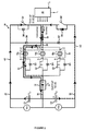
- the discharge current I DISCHARGE (shown as the solid line in Figure 4) flows from the injector 16a, through the inductor 18, through the closed switch Q2 and back to the negative terminal of the second capacitor C2.
- the select switches S2 and S3 remain open, and due to the direction of their associated diodes, D4 and D5 respectively, substantially no current is able to flow through the second and third injectors 16b, 16c.
- the current sensing and control means 14 monitors the current flow through the middle current path 30 as it builds up and, as soon as the upper current threshold level I 1 is reached, the output from the current sensing and control means 14 switches from a logic high to a logic low causing de-activation (opening) of the discharge switch Q2. At this point, the energy that is built up in the inductor 18 recirculates through the diode D8 associated with the charge (open) switch Q1. As a consequence, the direction of current flow through the inductor 18 and the selected one of the injectors 16a does not change. This is a "recirculation phase" of the discharge phase 6 of operation of the drive circuit 10. The recirculation discharge current is shown as the dashed line 42 in Figure 4.
- the current sensing and control means 14 monitors the recirculation current, so that when the recirculation current has fallen below the lower current threshold level (i.e. the recirculation current threshold) I 2 , the current sensing and control means 14 generates a signal to reactivate the discharge switch Q2 to continue the discharge operation.
- the varying current is driven through the stack 2 until the primary opening time POT expires.
- the second capacitor C2 provides energy, while the first capacitor C1 receives energy for storage.
- the discharge switch Q2 and the select switch S1 of the injector 16a are deactivated.
- the injector select switch S1 is deactivated before the discharge switch Q2 because the rate at which the current decays depends solely on the inductor 18: without deselecting the injector select switch S1 first, the current would decay slowly resulting in more charge than intended being removed from the stack 2. By deselecting the injector select switch S1 first, the current is forced to zero much quicker, and the additional charge removed is minimal.
- the discharge switch Q2 is deactivated substantially simultaneously or soon after the injector select switch S1
- the diode D7 provides a recirculation path for residual energy in the inductor 18 at the end of the discharge phase 6 in order to recirculate to the first capacitor C1 via the diode D8 associated with the charge switch Q1.
- the stack 2 of the selected injector 16a will be charged in order to close the injector to cease fuel delivery by varying the charge current between the upper and lower threshold levels, I 3 , I 4 , depending on the primary closing current set-point. Charging of the stack will not be described in detail here and can be found in the Applicant's co-pending application no. 06254039.8 .
- the varying current is driven through the stack 2 until the primary closing time PCT determined earlier expires.
- the first capacitor C 1 provides energy and the second capacitor C2 receives energy for storage.
- the charge switch Q1 and the select switch S1 of the injector 16a are deactivated.
- the injector select switch S1, S2, S3 or charge switch Q1 is deselected first. This is because at the end of the primary closing time PCT, the stack 2 is effectively charged to its initial high voltage level V0 and so, as a result, there can be only a minimal amount of current flowing (it is not possible to charge the stack 2 indefinitely due to its capacitive nature). This means that it is not possible to apply more charge than intended and ensures that the stack 2 is always recharged to a known state prior to the subsequent discharge. In essence, this is to ensure consistent fuel delivery.
- the stack 2 is not always fully charged during the charging phase 8, for example, in a merging pulse mode as described in co-pending European patent application no. 06252022.6 . If it is desirable that the stack 2 is not fully charged then it becomes important that the injector select switch S1, S2, S3 is deactivated before the charge switch Q1.
- the injectors 16a, 16b, 16c may be charged.
- the rate of charge (corresponding to the mean current level or set-point) is reduced towards the end of the discharging (opening) phase 6 in order to damp any displacement overshoot: this is the subject of co-pending patent application EP 06254039.8 .
- Reducing the rate of charge is achieved by dividing the discharge phase/opening time into two or more discharge stages, as described below and shown in Figure 6a.
- FIG. 6a shows a typical graph of current versus time for a discharge phase comprising two discharge stages, Stage 1 and Stage 2. Each discharge stage has a different rate of charge known as a discharge rate. Stage 1 corresponds to the primary opening time POT and the primary opening current set point PO, as described above, and Stage 2 corresponds to a secondary opening time SOT and a secondary opening current set point SO.
- Stage 1 is effectively a control phase, as the majority of opening control happens during this stage.
- Stage 2 is effectively a damping phase which is used to damp any displacement overshoot. However, a significant degree of needle lift also occurs in Stage 2.
- the secondary opening current set point SO and the secondary opening time SOT are derived in much the same way as the primary opening current set point PO and the primary opening time POT detailed above; for example look-up tables produce additional values for the secondary opening current set point SO and an associated secondary opening time SOT depending on stack pressure and stack temperature.
- the secondary opening current set point SO and the secondary opening time SOT are effectively independent of the primary opening current set point PO and the primary opening time POT by virtue of the fact that their values are stored in look-up tables.
- the microprocessor 20 outputs the primary opening upper current threshold level I 1 (derived from the primary opening current set point PO) for the primary opening time POT. At the expiry of the primary opening time POT, the microprocessor 20 outputs the secondary opening upper current threshold level I 1 (derived from the secondary opening current set point SO) for the duration of the secondary opening time SOT. The microprocessor 20 will continue to output appropriate upper current threshold levels for the required number of discharge levels to achieve the desired amount of discharge. The number of discharge (and charge) levels required is determined by the ECM control strategy.
- the varying current (corresponding to the primary opening current set point PO) is driven through the stack for the primary opening time POT; this causes the stack voltage to reduce at the first discharge rate PO from VO to V 1.
- the stack voltage remains substantially constant.
- the stack voltage is at V2 which is substantially equal to V1.
- the top voltage rail 28, the stack voltage and the bottom voltage rail 32 are described with reference to Ground.
- the top voltage rail is at 255V
- the middle voltage rail is at 55V
- the bottom voltage rail is at OV, i.e. Ground.
- the current and voltage graphs in Figures 6a and 6b can be considered as being typical of when the engine is warm. However, when the engine is cold, the graph of current versus time may look like the solid-line waveform X/Y in Figure 6c and the graph of stack voltage versus time may look like the solid-line waveform Z in Figure 6d. For comparative purposes, the current and voltage waveforms shown in Figures 6a and 6b have been overlaid as dotted-line waveforms in Figures 6c and 6d.
- the discharge switch is opened and closed in accordance with the chopped signal from the current sensing and control means 14. Effectively this is equivalent to switching the non-injector side of the inductor between the top voltage rail (255V) and the bottom voltage rail (OV), as shown in Figure 7.
- the injector side of the inductor 18, point P in Figure 7, is effectively the stack voltage V stack . Therefore, the voltage across the inductor V L switches between V L1 (i.e. V top - V stack ) and V L2 (i.e. V stack - V bottom ).
- the current set point PO, SO is determined on the basis of the amount of charge to be applied to/removed from.
- the current is then caused to vary between upper and lower current threshold levels I 1 , I 2 , which are dependent on the current set point PO, SO, for a determined time, POT, SOT respectively.
- the current varying between these thresholds should result in a mean current value equal to the current set point.
- a change in the rate of change of current i.e. a change in the gradient of the current
- a mean current value which does not equal the desired current set point.
- This change in rate of change of current corresponds to a variation in the charge applied to/removed from the stack. This is also shown with reference to the area under the current graph of Figure 6c which equates to the charge applied to/removed from the stack. As the gradient of the current waveform varies so too does the area under the graph, and hence the charge applied to/removed from the stack. An inconsistency in the amount of charge applied to/removed from the stack corresponds to an inconsistency in needle lift and fuel delivery, which as discussed above is undesirable.
- Figure 8 also shows a comparison between warm and cold engine scenarios.
- a warm engine may have a varying current waveform as shown by reference A
- a cold engine may have a varying current waveform as shown by reference B which shows a reduced rate of change of current. It is clear that the area under waveform B is larger than the area under waveform A. As a result, more charge than desired is applied to/removed from the stack when the engine is cold.
- Figure 6c is shown again in Figure 9a for reference.
- Figure 9b shows the chopped signal corresponding to the warm engine waveform A
- Figure 9c shows the chopped signal corresponding to the cold engine waveform B.
- the chop frequency reduces as the rate of change of current reduces, since it takes a longer time for the current to increase to the pre-determined upper current threshold level I 1 before the signal 'chops' to cause the current to reduce to the lower current threshold level I 2 .
- the voltage across the inductor is relatively large V L1' , causing the current to reduce rapidly to the lower current threshold level I 2 before it 'chops' again and is caused to increase, again, at the slower rate.
- 'chopping' effectively means that an increasing current starts to decrease and a decreasing current starts to increase.
- the time between chops is measured and compared with a predetermined threshold. Appropriate action can be taken if the time between chops is greater than the predetermined threshold.
- Figure 10 shows an example graph of the fuel volume delivery error versus minimum chop frequency measured during one discharge phase.
- the chop frequency is not constant during any discharge phase and it is foreseeable that only a few 'chops' are at the reduced frequency (i.e. have an increased period), which would cause over-delivery.
- it is the minimum chop frequency or the maximum time period between chops that is of most concern and has been represented approximately in Figure 10.
- a fuel volume delivery error causes either an increase (over-delivery) or decrease (under-delivery) in fuel volume delivery.
- the relationship between chop frequency i.e. the intervals between chops
- fuel volume delivery error is measured and mapped into a look-up table, thus allowing the error threshold to be determined.
- the ECM can identify when the chop frequency, in combination with current engine operating conditions (i.e. when the engine is near or at full load conditions), will cause an increase in fuel volume delivery, such that appropriate corrective action can be taken.
- the number of chop events during a stack discharge phase is counted. If the total number of chop events does not reach or pass a predetermined threshold, a fault flag may be set to cause appropriate corrective action to be taken to reduce the fuel volume delivered.
- the relationship between the stack voltage at the end of Stage 1 and the change in fuel volume delivery is measured and mapped into a look-up table, thus allowing an error threshold dependent on stack voltage to be determined.
- the ECM can identify when the stack voltage, in combination with current engine operating conditions (i.e. when the engine is near or at full load conditions), will cause an increase in fuel volume delivery, such that appropriate corrective action can be taken.
- One way in which the fuel volume delivery can be reduced is to reduce the amount of charge applied to/removed from the stack to reduce lift of the injector valve needle. In one embodiment, this is achieved by reducing the current set point.
- Another way in which the fuel volume delivery can be reduced is by reducing the time for which the current is applied in order to reduce the amount of charge applied to/removed from the stack.
- the time may be reduced by reducing either the primary opening time POT or the secondary opening time SOT or a combination of both.
- a third way in which the fuel volume delivery can be reduced is to reduce the injector on time T ON , which is the period between the start of the discharge phase and the start of the charge phase. Reducing the injector on time effectively shortens the time for which fuel is delivered and as such reduces the fuel volume delivery.
- the degree to which the current set points PO, SO, the discharge times POT, SOT and/or the injector on time T ON is/are reduced, is determined on the basis of the expected fuel volume delivery error which is be mapped into look-up tables against the expected fuel volume delivery.
- Figure 11 shows the correlation between a change in fuel volume delivery and a change in injector on time T ON , such that the injector on time T ON can be adjusted accordingly.
- a different look-up table is created for each of the adjustable parameters.
- Figure 12 shows a simple flowchart of the method steps required in order to determine whether it is necessary to adjust one of the parameters to prevent over fuelling.
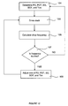
- a first step 101 the discharge parameters PO, POT, SO, SOT and the injector on time T ON are determined on the basis of the engine operating conditions and the demand on the engine.
- the stack is driven on the basis of these parameters.
- the chop frequency is calculated or measured by the microprocessor and is compared with the predetermined threshold in a fourth step 107. If it is determined that the chop frequency is above the threshold, control is passed back to the first step 101. However, if the frequency is below the threshold, one of the discharge parameters or injector on time TON is adjusted in a fifth step 109, and control is subsequently passed back to the second step 103 such that the stack is driven on the basis of the adjusted parameter.
- the present control method is a closed loop control method such that the corrections determined in one cycle are implemented in the next cycle in order to rectify the error.
- the chop frequency is measured.
- the method may be implemented by determining the stack voltage V stack at the end of Stage 1 and using that parameter to make the necessary adjustments.
- corrective action is taken when the fuel volume delivery is smaller than desired in order to prevent under-delivery, which in turn improves control and alleviates the above-identified inconsistencies.
Landscapes
- Engineering & Computer Science (AREA)
- Chemical & Material Sciences (AREA)
- Combustion & Propulsion (AREA)
- Mechanical Engineering (AREA)
- General Engineering & Computer Science (AREA)
- Fuel-Injection Apparatus (AREA)
- Electrical Control Of Air Or Fuel Supplied To Internal-Combustion Engine (AREA)
Abstract
Description
- The invention relates to a method of controlling a piezoelectric actuator for use in a fuel injector. More specifically, the invention relates to a method of operating a piezoelectrically actuated fuel injector in order to improve fuel volume delivery.
- In an internal combustion engine, it is known to deliver fuel into a cylinder of the engine by means of a fuel injector associated with each cylinder. One such type of fuel injector that permits precise metering of fuel is a so-called 'piezoelectric injector'.
- Typically, a piezoelectric injector includes a piezoelectric actuator that is operable to control an injection nozzle. The injection nozzle houses an injector valve needle which is movable relative to a valve needle seat under the control of the actuator. A hydraulic amplifier is situated between the actuator and the needle such that axial movement of the actuator causes an amplified axial movement of the needle. Depending on the amount of charge applied to/or removed from the piezoelectric actuator, the valve needle is either caused to disengage the valve seat, in which case fuel is delivered into the associated engine cylinder through a set of outlets provided in a tip of the nozzle, or is caused to engage the valve seat, in which case fuel delivery is prevented. The amount of charge is varied causing the valve needle to move between closed and open positions.
- The amount of charge applied to and removed from the piezoelectric actuator can be controlled in two ways. In a charge control method, a current is driven into or out of the piezoelectric actuator for a required time. Alternatively, in a voltage control method a current is driven into or out of the piezoelectric actuator until the voltage across the piezoelectric actuator reaches a required level. Regardless of how the piezoelectric actuator is controlled, the voltage across the piezoelectric actuator changes as the level of charge on the piezoelectric actuator varies and vice versa.
- It has been observed that when demands on the engine are high, and particularly when the engine temperature is low, there are inconsistencies in the amount of charge applied to and removed from the piezoelectric actuator. Since the amount of charge on the piezoelectric actuator determines the degree of valve needle lift, and hence fuel delivery, any inconsistencies in the amount of charge being applied or removed is undesirable.
- In particular, injecting a larger than desired volume of fuel when the demand on the engine is already high could result in the engine temperature and fuel pressure exceeding predetermined safety limits: exceeding such limits could result in irreparable damage to the engine.
- It is an object of the present invention to improve control of the piezoelectric actuator in order to alleviate the above-identified problem.
- According to a first aspect of the present invention there is provided a method for controlling the displacement of a stack of a piezoelectric actuator for use in a fuel injector in order to control fuel volume delivery, the method comprising causing a varying current to be driven into or out of the stack to charge or discharge the stack, respectively, during an opening phase, wherein the opening phase comprises at least a primary phase, measuring a parameter during the opening phase, comparing the measured parameter with a predetermined threshold value, and taking corrective action to adjust the fuel volume delivery, during a subsequent injection, depending on the result of the comparison.
- The present invention advantageously improves the control of a piezoelectric actuator and alleviates the problems associated with inconsistent fuel volume delivery, preventing damage to the engine.
- In a preferred embodiment the parameter is voltage and the method comprises measuring a voltage across the stack at the end of the primary phase, comparing the voltage across the stack with the predetermined threshold value, and taking corrective action to adjust the fuel volume delivery, during the subsequent injection, if the measured voltage across the stack is less than the predetermined threshold value.
- In an alternative embodiment the parameter is chop frequency and the method comprises measuring a minimum chop frequency of the varying current during the opening phase, comparing the minimum chop frequency with the predetermined threshold value, and taking corrective action to adjust the fuel volume delivery, during the subsequent injection, if the measured minimum chop frequency is less than the predetermined threshold value.
- In another alternative embodiment the parameter is chop period and the method comprises measuring a maximum chop period during the opening phase, comparing the maximum chop period with the predetermined threshold value, and taking corrective action to adjust the fuel volume delivery, during the subsequent injection, if the measured maximum chop period is more than the predetermined threshold value.
- Preferably, the method comprises varying the current between an upper current threshold level and a lower current threshold level and determining the upper and lower current thresholds from a current set-point level which is selectable such that the mean value of the varying current driven into or out of the stack for a time is intended to equal a desired amount of charge to be applied to or removed from the stack.
- In the preferred embodiment where the current is varied between an upper current threshold level and a lower current threshold level, the corrective action may comprise adjusting the current set-point level in order to adjust the amount of charge which is applied to or removed from the stack.
- Alternatively or additionally, the corrective action may comprise adjusting the time for which the varying current is driven into or out of the stack in order to adjust the amount of charge which is applied to or removed from the stack.
- In the embodiment where the current is varied between an upper current threshold level and a lower current threshold level, the method may further comprise determining an injector on time comprising the opening phase and a dwell phase, wherein the corrective action includes adjusting the injector on time in order to adjust the fuel volume delivery. Alternatively, the corrective action may comprise adjusting the current set-point level in order to adjust the amount of charge which is applied to or removed from the stack.
- Preferably, the comparing step further comprises comparing at least one of engine load, engine temperature, and fuel pressure with its respective threshold level, wherein corrective action is taken when at least one of engine load, engine temperature, and fuel pressure is above its threshold level.
- The corrective action may be taken in order to prevent more than a desired fuel volume delivery being delivered.
- Optionally, the corrective action may be taken in order to prevent less than a desired fuel volume delivery being delivered.
- In a second aspect, the invention also relates to a controller for a fuel injector for implementing a method in accordance with the first aspect of the invention.
- It will be appreciated that all of the steps of the method of the first aspect of the invention may be implemented within a controller of the second aspect of the invention.
- The invention extends to a computer program product comprising at least one computer program software portion which, when executed in an executing environment, is operable to implement the method of the present invention, and a data storage medium having the or each computer software portion stored thereon. The invention also extends to a microcomputer provided with the data storage medium.
- In this description reference to "rate of charge" means the rate of change in current over time, which may be as a result of either charging or discharging the piezoelectric actuator.
- Preferred embodiments of the invention will now be described, by way of example only, with reference to the accompanying drawings in which:
- Figure 1 is a schematic diagram of a piezoelectric actuator, including a stack of piezoelectric elements, with which the method of the present invention may be used;
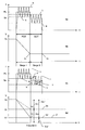
- Figure 2 includes ideal graphs of (a) charge versus time, (b) current versus time, (c) a discharge enable signal, (d) a charge enable signal, and (e) a chopped current control signal, for opening and closing phases of a fuel injector having a piezoelectric actuator as in Figure 1;
- Figure 3 is a circuit diagram of a drive circuit for implementing the method of the present invention;
- Figure 4 is the circuit diagram of Figure 3 showing the current paths around the drive circuit during a discharge phase;
- Figure 5 is the circuit diagram of Figure 3 showing the current paths around the drive circuit during a charge phase;
- Figure 6a is a graph of current versus time showing two discharge stages;
- Figure 6b is a graph of stack voltage versus time according to Figure 6a;
- Figure 6c is a further graph of current versus time showing variations in the rate of change of current (rate of charge);
- Figure 6d is a further graph of stack voltage versus time showing variations as a result of the variations in the rate of change of current in Figure 6c;
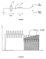
- Figure 7 is a schematic diagram of a piezoelectric fuel injector coupled to an inductor;
- Figure 8 is a graph of two current versus time waveforms showing variations in the charge applied to/removed from the piezoelectric actuator of the injector in Figure 7 as a variation in area under the respective waveforms;
- Figure 9a corresponds, for reference, to the graph in Figure 6c and shows a first and second current waveform;
- Figure 9b is a 'chopped signal' corresponding to the first current waveform in Figure 9a;
- Figure 9c is a 'chopped signal' corresponding to the second current waveform in Figure 9a;
- Figure 10 is an example waveform showing fuel volume delivery error versus 'chop frequency';
- Figure 11 is a graph of fuel volume delivery versus 'injector on time' TON; and
- Figure 12 is a flowchart of the steps of operation of the method of the present invention.
- Figure 1 shows a schematic diagram of a
piezoelectric actuator 1 including astack 2 of capacitivepiezoelectric elements 4, which are effectively connected in parallel. The actuator is of the type suitable for use in a fuel injector of the type described inEP 1174615 having a valve needle which is operable by means of the actuator. - The
stack 2 is charged to different energisation levels by driving a current I into or out of thestack 2 for a given time t, in accordance with the relationship below:
- Figure 2(a) shows a typical graph of charge versus time for an
actuator 1, which is driven from a closed non-injecting position to an open injecting position (i.e. an opening/discharging phase 6) and back again to the non-injecting position (i.e. a closing/charging phase 8). During theopening phase 6 the charge changes from a first charge level Q1 to a second charge level Q2 over a time topen. The difference between Q1 and Q2 equals a change in charge ΔQ, which corresponds to the length of thestack 2 changing from a relativelylong length L 1 to a relatively short length L2, as shown in Figure 1. The change in length of thestack 2 directly controls movement of an injector valve needle, and hence controls fuel delivery. - The aforementioned method of controlling a
piezoelectric actuator 1 is referred to as a charge control method. It is possible to operate an actuator using this method by determining how much charge is to be applied to/removed from the stack, and applying/removing an appropriate current to/from thestack 2 for the required time in accordance with the equation above. In practice a varying current is used for charging and discharging the stack. The mean value of the current is known, and will be referred to as the current set point or level. Figure 2(b) also shows a typical graph of current versus time, for a varying current (the mean value/set point is shown by the dashed line), which is applied to thestack 2 in order to achieve the charge waveform shown in Figure 2(a). - The drive circuit in Figure 3 is arranged to drive an
injector bank 16 comprising first, second andthird injectors injectors inductor 18, a charge switch Q1, a discharge switch Q2, and amicroprocessor 20. Each of the injector select switches S1, S2, S3 typically takes the form of an insulated gate bipolar transistor (IGBT) having a gate coupled to a gate drive which is powered at a bias supply input. The charge and discharge switches Q1, Q2 may take the form of an n-channel IGBT having a gate controlling current flow from the collector to the emitter. - The first voltage supply VS1 is connected across a
top voltage rail 28, which is at a top voltage level Vtop, and a middle voltage rail known as a bi-directional middlecurrent path 30, which is at a stack voltage level Vstack. The second voltage supply VS2 is connected across themiddle voltage rail 30 and abottom voltage rail 32 which is at a bottom voltage level Vbottom. - The first energy
storage capacitor C 1 is connected between thetop voltage rail 28 and the middlecurrent path 30, and the second storage capacitor C2 is connected between the middlecurrent path 30 andbottom voltage rail 32. The current flow sensing and control means 14 is connected in the middlecurrent path 30, between a connection point between the first and second storage capacitors C1, C2 and theinjector bank 16. - The
injectors injector injectors drive circuit 10, and connections x and y are provided, to thedrive circuit 10, through appropriate connecting leads. - The negative terminals of each of the
injectors injectors inductor 18. - A diode D6 is provided between the middle
current path 30 on the injector side of theinductor 18 and thetop voltage rail 28, and another diode D7 is provided between thebottom voltage rail 32 and the middlecurrent path 30, again, on the injector side of theinductor 18. The diode D6 provides a 'voltage clamping effect' for a selectedinjector charge phase 8, and prevents theinjector discharge phase 6 of operation, as described in further detail below. - The charge switch Q1 is connected between the non-injector side of the
inductor 18 and thetop voltage rail 28, and a diode D8 is connected in parallel across it. Likewise, the discharge switch Q2 is connected between thebottom voltage rail 32 and the non-injector side of theinductor 18, and similarly, a diode D9 is connected in parallel across it. - The output Is of the current flow sensing and control means 14 is fed into an input of the
microprocessor 20, which provides control signals for the current flow sensing and control means 14, the injector select switches S1, S2, S3, the charge switch Q1, and the discharge switch Q2. The control signals for the discharge and charge switches Q2, Q1 are referred to as a discharge enablesignal 34 and a charge enablesignal 36, respectively. - By controlling the injector select switches S1, S2, S3, the charge switch Q1, and the discharge switch Q2, it is possible to drive a varying current through the
stack 2, for the required time, such that thestack 2 is charged/discharged, and fuel delivery is controlled accordingly. - Referring also to Figure 2(b), 2(c), 2(d) and 2(e), the current is caused to vary between an upper current threshold level I1 and a lower current threshold level I2 under the control of the current sensing and control means 14 in conjunction with the
microprocessor 20. The current sensing and control means 14 monitors the current flow and generates a chopped signal 38 (Figure 2(e)) on the basis of the 'sensed' current Is. This will be described in further detail below. The choppedsignal 38 is combined with a discharge enable signal 34 (Figure 2(c)) through a logical AND gate, and the resultant signal is applied to the discharge switch Q2. The choppedsignal 38 is also combined with a charge enable signal 36 (Figure 2(d) through a logical AND gate, and that resultant signal is applied to the charge switch Q1. The discharge switch Q2 opens and closes to effectively generate the varying current signal in thedischarge phase 6. In thecharge phase 8, it is the charge switch Q1 that controls generation of the varying current. - Look-up tables within the microprocessor's memory store values for a primary opening current set point PO, a primary opening time POT, and a primary closing current set point PC. The
microprocessor 20 selects the value of primary opening current set point PO, primary opening time POT, and primary closing time depending on stack pressure, stack temperature, and a demanded injector on time TON (which is determined from the fuel demand and is also a function of the fuel rail pressure). Thedrive circuit 10, and hence fuel delivery, are controlled by an engine control module (ECM). The ECM incorporates strategies to determine the required fuelling and timing of injection pulses based on the current engine operating conditions, including torque, engine speed and operating temperature. The timing of when the injectors open and close is determined by the ECM and is not important to the understanding of the present invention. - During the
discharge phase 6, the value for the primary opening current set point PO is converted by themicroprocessor 20 into a corresponding upper current threshold level I1. While it is possible for themicroprocessor 20 to generate both the upper and lower current threshold levels I1, I2, in practice it is simpler to generate just the upper current threshold level I1, and use a potential divider to generate the lower current threshold level I2 as a fixed proportion of the upper current threshold level I1. Similarly during thecharge phase 8, themicroprocessor 20 generates an upper current threshold level I3 corresponding to the primary closing current set point PC. Likewise, for the charging phase, the potential divider is arranged to generate a lower current threshold I4. Themicroprocessor 20 outputs one upper current threshold level I1, I3 at a time. - The required upper current threshold level I1 is output from the
microprocessor 20 to the current sensing and control means 14 at the appropriate time depending on the injection timing according to the ECM and the selected primary opening time POT. In other words, for the duration of the primary opening time POT, the upper current threshold level I1 corresponding to the primary opening current set point PO is output from themicroprocessor 20. In a similar manner, during the charge phase the upper current threshold level I3 corresponding to the primary closing current set point PC is output from themicroprocessor 20 for the duration of a determined primary closing time PCT. The primary closing time PCT is determined such that the amount of charge removed during the opening/discharge phase 6 is re-applied during the closing/charge phase 8, depending on the primary closing current set point PC derived from the look-up tables. - The upper and lower current threshold levels I1, I2, I3, I4 are such that the mean current produced meets the primary opening current set point PO and primary closing current set point PC. It is to be appreciated that it is more convenient to refer to the mean current since it is this current, and the time that it is applied for, which determines the amount of charge applied or removed from the actuator. The upper current threshold levels I1, I3 and the lower current threshold levels I2, I4 produced by the potential divider, determine the limits of current variation.
- To inject with a
particular injector microprocessor 20. For example, referring to Figure 4, if it is required to inject with thefirst injector 16a, the select switch S1 is closed. The other two injector select switches S2, S3 of the bank remain de-activated at this time as the second andthird injectors - In addition, the discharge enable
signal 34 goes from a logic low to a logic high. The current sensing and control means 14 initially outputs a logic high signal, and this and the high discharge enablesignal 34 causes the discharge switch Q2 to close. Current is allowed to flow from the 100 V supply across the second capacitor C2, through the current sensing and control means 14, through the selected switch (S 1 in this example), and into the corresponding negative side of the selected injector (16a in this example). The discharge current IDISCHARGE (shown as the solid line in Figure 4) flows from theinjector 16a, through theinductor 18, through the closed switch Q2 and back to the negative terminal of the second capacitor C2. As the select switches S2 and S3 remain open, and due to the direction of their associated diodes, D4 and D5 respectively, substantially no current is able to flow through the second andthird injectors - The current sensing and control means 14 monitors the current flow through the middle
current path 30 as it builds up and, as soon as the upper current threshold level I1 is reached, the output from the current sensing and control means 14 switches from a logic high to a logic low causing de-activation (opening) of the discharge switch Q2. At this point, the energy that is built up in theinductor 18 recirculates through the diode D8 associated with the charge (open) switch Q1. As a consequence, the direction of current flow through theinductor 18 and the selected one of theinjectors 16a does not change. This is a "recirculation phase" of thedischarge phase 6 of operation of thedrive circuit 10. The recirculation discharge current is shown as the dashedline 42 in Figure 4. - During the recirculation phase, current flows from the negative side of the first voltage source VS1 across the first capacitor C1, through the current sensing and control means 14, through the selected injector select switch S1, through the selected
injector 16a, through theinductor 18, and finally through the diode D8 and into the positive side of the first capacitor C1. Thus, energy from theinductor 18 and the selected one of theinjectors 16a is transferred to the first capacitor C1 during the recirculation phase for energy storage purposes. The current sensing and control means 14 monitors the recirculation current, so that when the recirculation current has fallen below the lower current threshold level (i.e. the recirculation current threshold) I2, the current sensing and control means 14 generates a signal to reactivate the discharge switch Q2 to continue the discharge operation. - The varying current is driven through the
stack 2 until the primary opening time POT expires. In thisdischarge phase 6, the second capacitor C2 provides energy, while the first capacitor C1 receives energy for storage. At the end of the primary opening time POT, the discharge switch Q2 and the select switch S1 of theinjector 16a are deactivated. - It is desirable that the injector select switch S1 is deactivated before the discharge switch Q2 because the rate at which the current decays depends solely on the inductor 18: without deselecting the injector select switch S1 first, the current would decay slowly resulting in more charge than intended being removed from the
stack 2. By deselecting the injector select switch S1 first, the current is forced to zero much quicker, and the additional charge removed is minimal. Where the discharge switch Q2 is deactivated substantially simultaneously or soon after the injector select switch S1, the diode D7 provides a recirculation path for residual energy in theinductor 18 at the end of thedischarge phase 6 in order to recirculate to the first capacitor C1 via the diode D8 associated with the charge switch Q1. - At the appropriate time, the
stack 2 of the selectedinjector 16a will be charged in order to close the injector to cease fuel delivery by varying the charge current between the upper and lower threshold levels, I3, I4, depending on the primary closing current set-point. Charging of the stack will not be described in detail here and can be found in the Applicant's co-pending applicationno. 06254039.8 - The varying current is driven through the
stack 2 until the primary closing time PCT determined earlier expires. In thischarging phase 8, thefirst capacitor C 1 provides energy and the second capacitor C2 receives energy for storage. At the end of the primary closing time PCT (charge time), the charge switch Q1 and the select switch S1 of theinjector 16a are deactivated. - Generally, it is not critical at the end of the
charge phase 8, as it is at the end of thedischarge phase 6, whether the injector select switch S1, S2, S3 or charge switch Q1 is deselected first. This is because at the end of the primary closing time PCT, thestack 2 is effectively charged to its initial high voltage level V0 and so, as a result, there can be only a minimal amount of current flowing (it is not possible to charge thestack 2 indefinitely due to its capacitive nature). This means that it is not possible to apply more charge than intended and ensures that thestack 2 is always recharged to a known state prior to the subsequent discharge. In essence, this is to ensure consistent fuel delivery. - There is a closed loop system, which does not form part of the present invention, that operates to keep the voltage across the stack between injections at the high voltage level V0. Therefore, at the start of any discharge phase the stack is always at a known reference voltage.
- A person skilled in the art will comprehend that the
stack 2 is not always fully charged during thecharging phase 8, for example, in a merging pulse mode as described in co-pendingEuropean patent application no. 06252022.6 stack 2 is not fully charged then it becomes important that the injector select switch S1, S2, S3 is deactivated before the charge switch Q1. - It is to be appreciated that there are other ways in which the
injectors injectors stack 2 when only thecharge switch Q 1 is activated (closed). - Typically, the rate of charge (corresponding to the mean current level or set-point) is reduced towards the end of the discharging (opening)
phase 6 in order to damp any displacement overshoot: this is the subject of co-pending patent applicationEP 06254039.8 - Figure 6a shows a typical graph of current versus time for a discharge phase comprising two discharge stages,
Stage 1 andStage 2. Each discharge stage has a different rate of charge known as a discharge rate.Stage 1 corresponds to the primary opening time POT and the primary opening current set point PO, as described above, andStage 2 corresponds to a secondary opening time SOT and a secondary opening current set point SO. - It is to be appreciated that there could be more than two discharge stages. However, for the purposes of describing the present invention a discharge phase comprising only two discharge stages will be discussed. In addition, it is to be appreciated that the present invention also applies where there is only one discharge stage and rate.
-
Stage 1 is effectively a control phase, as the majority of opening control happens during this stage.Stage 2 is effectively a damping phase which is used to damp any displacement overshoot. However, a significant degree of needle lift also occurs inStage 2. - The secondary opening current set point SO and the secondary opening time SOT are derived in much the same way as the primary opening current set point PO and the primary opening time POT detailed above; for example look-up tables produce additional values for the secondary opening current set point SO and an associated secondary opening time SOT depending on stack pressure and stack temperature.
- Typically, the secondary opening current set point SO and the secondary opening time SOT are effectively independent of the primary opening current set point PO and the primary opening time POT by virtue of the fact that their values are stored in look-up tables.
- As described above, the
microprocessor 20 outputs the primary opening upper current threshold level I1 (derived from the primary opening current set point PO) for the primary opening time POT. At the expiry of the primary opening time POT, themicroprocessor 20 outputs the secondary opening upper current threshold level I1 (derived from the secondary opening current set point SO) for the duration of the secondary opening time SOT. Themicroprocessor 20 will continue to output appropriate upper current threshold levels for the required number of discharge levels to achieve the desired amount of discharge. The number of discharge (and charge) levels required is determined by the ECM control strategy. - In addition, it is known to switch off the injector select switch S1, S2, S3 between
Stage 1 andStage 2, i.e. at the end of the primary opening time POT, in order to eliminate variations in charge delivery when multiple charge levels PO, SO, PC are employed, and to improve accuracy in charge control during current level changes over a large number of operating conditions. - A graph of the stack voltage versus time, corresponding to the current waveform in Figure 6a, is shown in Figure 6b. For
Stage 1, the varying current (corresponding to the primary opening current set point PO) is driven through the stack for the primary opening time POT; this causes the stack voltage to reduce at the first discharge rate PO from VO toV 1. DuringStage 2, current is driven in to or out of the stack at the reduced second discharge rate SO, causing the charge on the stack to increase or decrease, and the needle to lift, accordingly. However, the stack voltage remains substantially constant. At the end ofStage 2 the stack voltage is at V2 which is substantially equal to V1. - For ease of reference, in the following description the
top voltage rail 28, the stack voltage and thebottom voltage rail 32 are described with reference to Ground. In the examples in this description, the top voltage rail is at 255V, the middle voltage rail is at 55V and the bottom voltage rail is at OV, i.e. Ground. - The current and voltage graphs in Figures 6a and 6b can be considered as being typical of when the engine is warm. However, when the engine is cold, the graph of current versus time may look like the solid-line waveform X/Y in Figure 6c and the graph of stack voltage versus time may look like the solid-line waveform Z in Figure 6d. For comparative purposes, the current and voltage waveforms shown in Figures 6a and 6b have been overlaid as dotted-line waveforms in Figures 6c and 6d.
- One reason for the difference in these graphs is due to the capacitance of the stack changing with temperature. More specifically, the capacitance of the stack reduces as the temperature reduces.
- In accordance with the relationship Q = VC, as the capacitance reduces for the same charge (charge = current x time) applied to/removed from the stack, the magnitude of the voltage change across the stack increases. In other words, starting from an initial voltage level of V0 the stack voltage reduces to V1' rather than to V1, as shown by the solid line. Likewise, at the end of
Stage 2 the stack voltage is at V2' rather than at V2. As described above V2' is substantially equal to V1'. - As described above with reference to Figure 3, the discharge switch is opened and closed in accordance with the chopped signal from the current sensing and control means 14. Effectively this is equivalent to switching the non-injector side of the inductor between the top voltage rail (255V) and the bottom voltage rail (OV), as shown in Figure 7. The injector side of the
inductor 18, point P in Figure 7, is effectively the stack voltage Vstack. Therefore, the voltage across the inductor VL switches between VL1 (i.e. Vtop - Vstack) and VL2 (i.e. Vstack - Vbottom). - The voltage across the inductor has a direct affect on the current flowing through the circuit during discharge since:

where di/dt equals the rate of change of current, and V is the voltage across the inductor L. - In the case when the engine is warm, the voltage across the stack switches from VL1 to VL2. However, in the example when the engine is cold, the change in voltage across the stack increases such that the stack voltage itself reduces to a value nearer the bottom voltage rail Vbottom. Therefore, the voltage across the inductor switches between VL1, and VL2', where VL1, is larger than VL1, and VL2' is smaller than VL2, as shown in Figure 6d.
- In accordance with the di/dt equation above, when the voltage across the
inductor 18 is reduced (i.e. VL2' being smaller than VL2), the rate of change of current through theinductor 18 is also reduced. This is shown in Figure 6c as a shallower current gradient X. Conversely, when the voltage across theinductor 18 is increased, the rate of change of current is also increased (VL1, being larger than VL1), corresponding to a steeper gradient Y. - As described above, the current set point PO, SO is determined on the basis of the amount of charge to be applied to/removed from. The current is then caused to vary between upper and lower current threshold levels I1, I2, which are dependent on the current set point PO, SO, for a determined time, POT, SOT respectively. The current varying between these thresholds should result in a mean current value equal to the current set point. However, a change in the rate of change of current (i.e. a change in the gradient of the current) caused by the reduced or increased voltage across the inductor can result in a mean current value which does not equal the desired current set point. This change in rate of change of current, as shown in Figure 6c, corresponds to a variation in the charge applied to/removed from the stack. This is also shown with reference to the area under the current graph of Figure 6c which equates to the charge applied to/removed from the stack. As the gradient of the current waveform varies so too does the area under the graph, and hence the charge applied to/removed from the stack. An inconsistency in the amount of charge applied to/removed from the stack corresponds to an inconsistency in needle lift and fuel delivery, which as discussed above is undesirable.
- Figure 8 also shows a comparison between warm and cold engine scenarios. A warm engine may have a varying current waveform as shown by reference A, and a cold engine may have a varying current waveform as shown by reference B which shows a reduced rate of change of current. It is clear that the area under waveform B is larger than the area under waveform A. As a result, more charge than desired is applied to/removed from the stack when the engine is cold.
- However, the problem regarding the reduction in voltage across the inductor could equally have resulted in a smaller than desired amount of charge being applied to/removed from, and therefore a reduced fuel volume being delivered. In practice, delivering a smaller than desired fuel volume is not as severe as delivering a larger than desired fuel volume. An increase in fuel volume delivery (over-delivery) is especially critical when the engine is already at or near full load. Delivering a larger fuel volume in that scenario could cause an increase in engine temperature and combustion pressure above safe limits, and this could potentially cause damage to the engine.
- It is the object of the invention to alleviate the above-identified problems, and in one embodiment this is achieved by measuring a chop frequency of the chopped signal generated by the current flow sensing and control means 14 of the
drive circuit 10. - Figure 6c is shown again in Figure 9a for reference. Figure 9b shows the chopped signal corresponding to the warm engine waveform A, and Figure 9c shows the chopped signal corresponding to the cold engine waveform B. As shown by comparing Figure 9b and 9c, the chop frequency reduces as the rate of change of current reduces, since it takes a longer time for the current to increase to the pre-determined upper current threshold level I1 before the signal 'chops' to cause the current to reduce to the lower current threshold level I2. As described above, at the point where the increasing current 'chops', the voltage across the inductor is relatively large VL1', causing the current to reduce rapidly to the lower current threshold level I2 before it 'chops' again and is caused to increase, again, at the slower rate. Where the current 'chops' it does not change direction; 'chopping' effectively means that an increasing current starts to decrease and a decreasing current starts to increase.
- In order to compensate for the error in fuel volume delivery, the time between chops is measured and compared with a predetermined threshold. Appropriate action can be taken if the time between chops is greater than the predetermined threshold.
- Figure 10 shows an example graph of the fuel volume delivery error versus minimum chop frequency measured during one discharge phase. The chop frequency is not constant during any discharge phase and it is foreseeable that only a few 'chops' are at the reduced frequency (i.e. have an increased period), which would cause over-delivery. As such, it is the minimum chop frequency or the maximum time period between chops that is of most concern and has been represented approximately in Figure 10. As shown, above a certain minimum chop frequency there is little or no error in fuel delivery resulting from the change in rate of change of current. However, below a certain minimum chop frequency, i.e. known as an error threshold, a fuel volume delivery error causes either an increase (over-delivery) or decrease (under-delivery) in fuel volume delivery.
- In one embodiment, during calibration the relationship between chop frequency (i.e. the intervals between chops) and fuel volume delivery error is measured and mapped into a look-up table, thus allowing the error threshold to be determined. During operation of the engine, the ECM can identify when the chop frequency, in combination with current engine operating conditions (i.e. when the engine is near or at full load conditions), will cause an increase in fuel volume delivery, such that appropriate corrective action can be taken.
- In an alternative embodiment, the number of chop events during a stack discharge phase is counted. If the total number of chop events does not reach or pass a predetermined threshold, a fault flag may be set to cause appropriate corrective action to be taken to reduce the fuel volume delivered.
- In a further alternative embodiment, during calibration the relationship between the stack voltage at the end of
Stage 1 and the change in fuel volume delivery is measured and mapped into a look-up table, thus allowing an error threshold dependent on stack voltage to be determined. During operation of the engine, the ECM can identify when the stack voltage, in combination with current engine operating conditions (i.e. when the engine is near or at full load conditions), will cause an increase in fuel volume delivery, such that appropriate corrective action can be taken. - As stated above, it is important to be able to reduce the fuel volume delivery to prevent over fuelling and damage to the engine. There are three courses of corrective action which could be taken to reduce the fuel volume delivery.
- One way in which the fuel volume delivery can be reduced is to reduce the amount of charge applied to/removed from the stack to reduce lift of the injector valve needle. In one embodiment, this is achieved by reducing the current set point.
- Another way in which the fuel volume delivery can be reduced is by reducing the time for which the current is applied in order to reduce the amount of charge applied to/removed from the stack. In practice, the time may be reduced by reducing either the primary opening time POT or the secondary opening time SOT or a combination of both.
- A third way in which the fuel volume delivery can be reduced is to reduce the injector on time TON, which is the period between the start of the discharge phase and the start of the charge phase. Reducing the injector on time effectively shortens the time for which fuel is delivered and as such reduces the fuel volume delivery.
- It is to be appreciated, that a combination of the above methods could be used to reduce needle lift and prevent over delivery.
- The degree to which the current set points PO, SO, the discharge times POT, SOT and/or the injector on time TON is/are reduced, is determined on the basis of the expected fuel volume delivery error which is be mapped into look-up tables against the expected fuel volume delivery. For example, Figure 11 shows the correlation between a change in fuel volume delivery and a change in injector on time TON, such that the injector on time TON can be adjusted accordingly. A different look-up table is created for each of the adjustable parameters.
- Figure 12 shows a simple flowchart of the method steps required in order to determine whether it is necessary to adjust one of the parameters to prevent over fuelling.
- In a
first step 101, the discharge parameters PO, POT, SO, SOT and the injector on time TON are determined on the basis of the engine operating conditions and the demand on the engine. In asecond step 103, the stack is driven on the basis of these parameters. In athird step 105, the chop frequency is calculated or measured by the microprocessor and is compared with the predetermined threshold in afourth step 107. If it is determined that the chop frequency is above the threshold, control is passed back to thefirst step 101. However, if the frequency is below the threshold, one of the discharge parameters or injector on time TON is adjusted in afifth step 109, and control is subsequently passed back to thesecond step 103 such that the stack is driven on the basis of the adjusted parameter. - It is to be appreciated that the present control method is a closed loop control method such that the corrections determined in one cycle are implemented in the next cycle in order to rectify the error. In the above example, the chop frequency is measured. However, the method may be implemented by determining the stack voltage Vstack at the end of
Stage 1 and using that parameter to make the necessary adjustments. - In another embodiment, corrective action is taken when the fuel volume delivery is smaller than desired in order to prevent under-delivery, which in turn improves control and alleviates the above-identified inconsistencies.
- It is to be appreciated that the above-identified problem relating to a reduced voltage across the inductor, resulting in a slow rate of change of current, also applies when the stack is being charged during the closing phase. In a further embodiment, corrective action is taken near or at the end of the closing/charging phase to ensure that the charge on the stack at the end of the closing phase is at the desired level for a subsequent discharge phase.
- Furthermore, it is to be appreciated that although the present invention is described above in relation to de-energise-to-inject injectors, the present invention can also be implemented with energise-to-inject injectors.
- It is also to be appreciated that power supply circuits other than those shown in Figure 3 may be suitable for use with this invention.
Claims (15)
- A method for controlling the displacement of a stack (2) of a piezoelectric actuator (1) for use in a fuel injector in order to control fuel volume delivery, the method comprising;
causing a varying current to be driven into or out of the stack (2) to charge or discharge the stack (2), respectively, during an opening phase (6), wherein the opening phase (6) comprises at least a primary phase (POT, PCT),
measuring a parameter during the opening phase (6),
comparing the measured parameter with a predetermined threshold value, and
taking corrective action to adjust the fuel volume delivery, during a subsequent injection, depending on the result of the comparison. - The method as claimed in Claim 1, wherein the parameter is voltage (Vstack) and the method comprises measuring a voltage across the stack (Vstack) at the end of the primary phase (POT, PCT), comparing the voltage across the stack (Vstack) with the predetermined threshold value, and taking corrective action to adjust the fuel volume delivery, during the subsequent injection, if the measured voltage across the stack (Vstack) is less than the predetermined threshold value.
- The method as claimed in Claim 1, wherein the parameter is chop frequency and the method comprises measuring a minimum chop frequency of the varying current during the opening phase (6), comparing the minimum chop frequency with the predetermined threshold value, and taking corrective action to adjust the fuel volume delivery, during the subsequent injection, if the measured minimum chop frequency is less than the predetermined threshold value.
- The method as claimed in Claim 1, wherein the parameter is chop period and the method comprises measuring a maximum chop period during the opening phase (6), comparing the maximum chop period with the predetermined threshold value, and taking corrective action to adjust the fuel volume delivery, during the subsequent injection, if the measured maximum chop period is more than the predetermined threshold value.
- The method as claimed in any preceding claim, comprising varying the current between an upper current threshold level (I1, I3) and a lower current threshold level (I2, I4) and determining the upper and lower current thresholds (I1, I2, I3, I4) from a current set-point level (PO, SO, PC) which is selectable such that the mean value of the varying current driven into or out of the stack (2) for a time (t) is intended to equal a desired amount of charge to be applied to or removed from the stack (2).
- The method as claimed in Claim 5, wherein the corrective action comprises adjusting the current set-point level (PO, SO, PC) in order to adjust the amount of charge which is applied to or removed from the stack (2).
- The method as claimed in Claim 5 or Claim 6, wherein the corrective action comprises adjusting the time (t) for which the varying current is driven into or out of the stack (2) in order to adjust the amount of charge which is applied to or removed from the stack (2).
- The method as claimed in Claim 5 or Claim 6, further comprising determining an injector on time (TON) comprising the opening phase (6) and a dwell phase (tdwell), wherein the corrective action includes adjusting the injector on time (TON) in order to adjust the fuel volume delivery.
- The method as claimed in any preceding claim, wherein the comparing step further comprises comparing at least one of engine load, engine temperature, and fuel pressure with its respective threshold level, wherein corrective action is taken when at least one of engine load, engine temperature, and fuel pressure is above its threshold level.
- The method as claimed in any preceding claim, comprising taking corrective action in order to prevent more than a desired fuel volume delivery being delivered.
- The method as claimed in any preceding claim, comprising taking corrective action in order to prevent less than a desired fuel volume delivery being delivered.
- A computer program product comprising at least one computer program software portion which, when executed in an executing environment, is operable to implement the method of any one of Claims 1 to 11.
- A data storage medium having the or each computer software portion of Claim 12 stored thereon.
- A microcomputer provided with the data storage medium of Claim 13.
- A controller for a stack (2) of a piezoelectric actuator (1) for use in a fuel injector, the controller comprising;
means for causing a varying current to be driven into or out of the stack (2) to charge or discharge the stack (2), respectively, during an opening phase (6),
means for measuring a parameter during the opening phase (6),
means for comparing the measured parameter with a predetermined threshold value, and
means for taking corrective action to adjust the fuel volume delivery, during a subsequent injection, depending on the result of the comparison.
Priority Applications (3)
| Application Number | Priority Date | Filing Date | Title |
|---|---|---|---|
| EP06255815A EP1923559B1 (en) | 2006-11-14 | 2006-11-14 | A method of controlling a piezoelectric actuator |
| DE602006009683T DE602006009683D1 (en) | 2006-11-14 | 2006-11-14 | Method for controlling a piezoelectric actuator |
| AT06255815T ATE445094T1 (en) | 2006-11-14 | 2006-11-14 | METHOD FOR CONTROLLING A PIEZOELECTRIC ACTUATOR |
Applications Claiming Priority (1)
| Application Number | Priority Date | Filing Date | Title |
|---|---|---|---|
| EP06255815A EP1923559B1 (en) | 2006-11-14 | 2006-11-14 | A method of controlling a piezoelectric actuator |
Publications (2)
| Publication Number | Publication Date |
|---|---|
| EP1923559A1 true EP1923559A1 (en) | 2008-05-21 |
| EP1923559B1 EP1923559B1 (en) | 2009-10-07 |
Family
ID=38190821
Family Applications (1)
| Application Number | Title | Priority Date | Filing Date |
|---|---|---|---|
| EP06255815A Not-in-force EP1923559B1 (en) | 2006-11-14 | 2006-11-14 | A method of controlling a piezoelectric actuator |
Country Status (3)
| Country | Link |
|---|---|
| EP (1) | EP1923559B1 (en) |
| AT (1) | ATE445094T1 (en) |
| DE (1) | DE602006009683D1 (en) |
Cited By (5)
| Publication number | Priority date | Publication date | Assignee | Title |
|---|---|---|---|---|
| EP2136062A1 (en) * | 2008-05-27 | 2009-12-23 | Delphi Technologies, Inc. | Improvements Relating to Fuel Injector Control |
| WO2010094516A1 (en) * | 2009-02-23 | 2010-08-26 | Robert Bosch Gmbh | Method for operating a final stage for at least one piezoactuator |
| GB2480076A (en) * | 2010-05-05 | 2011-11-09 | Gm Global Tech Operations Inc | Method for controlling a directly acting piezoelectric injector of an internal combustion engine |
| CN109488654A (en) * | 2018-12-19 | 2019-03-19 | 中国石油化工股份有限公司 | A kind of electro-hydraulic actuator displacement control method |
| CN116447030A (en) * | 2023-04-26 | 2023-07-18 | 潍柴动力股份有限公司 | Method and device for determining injection driving mode of injection valve and injection system |
Citations (3)
| Publication number | Priority date | Publication date | Assignee | Title |
|---|---|---|---|---|
| DE10314565A1 (en) | 2002-04-01 | 2003-11-13 | Denso Corp | Piezo actuator driving circuit for fuel injection equipment has controller which, upon determining occurrence of short circuit, discharges electric charge of capacitor and piezo stacks |
| GB2399656A (en) | 2003-03-14 | 2004-09-22 | Bosch Gmbh Robert | A method for controlling the actuation of a piezo-electric element in a fuel injector |
| JP2005163549A (en) | 2003-11-28 | 2005-06-23 | Nissan Diesel Motor Co Ltd | Injector drive device |
-
2006
- 2006-11-14 EP EP06255815A patent/EP1923559B1/en not_active Not-in-force
- 2006-11-14 AT AT06255815T patent/ATE445094T1/en not_active IP Right Cessation
- 2006-11-14 DE DE602006009683T patent/DE602006009683D1/en active Active
Patent Citations (3)
| Publication number | Priority date | Publication date | Assignee | Title |
|---|---|---|---|---|
| DE10314565A1 (en) | 2002-04-01 | 2003-11-13 | Denso Corp | Piezo actuator driving circuit for fuel injection equipment has controller which, upon determining occurrence of short circuit, discharges electric charge of capacitor and piezo stacks |
| GB2399656A (en) | 2003-03-14 | 2004-09-22 | Bosch Gmbh Robert | A method for controlling the actuation of a piezo-electric element in a fuel injector |
| JP2005163549A (en) | 2003-11-28 | 2005-06-23 | Nissan Diesel Motor Co Ltd | Injector drive device |
Cited By (8)
| Publication number | Priority date | Publication date | Assignee | Title |
|---|---|---|---|---|
| EP2136062A1 (en) * | 2008-05-27 | 2009-12-23 | Delphi Technologies, Inc. | Improvements Relating to Fuel Injector Control |
| WO2010094516A1 (en) * | 2009-02-23 | 2010-08-26 | Robert Bosch Gmbh | Method for operating a final stage for at least one piezoactuator |
| CN102325984B (en) * | 2009-02-23 | 2014-06-18 | 罗伯特·博世有限公司 | Method for operating final stage for at least one piezoactuator |
| US8952597B2 (en) | 2009-02-23 | 2015-02-10 | Robert Bosch Gmbh | Method for operating an output stage for at least one piezoactuator |
| GB2480076A (en) * | 2010-05-05 | 2011-11-09 | Gm Global Tech Operations Inc | Method for controlling a directly acting piezoelectric injector of an internal combustion engine |
| CN109488654A (en) * | 2018-12-19 | 2019-03-19 | 中国石油化工股份有限公司 | A kind of electro-hydraulic actuator displacement control method |
| CN109488654B (en) * | 2018-12-19 | 2020-04-17 | 中国石油化工股份有限公司 | Displacement control method of electro-hydraulic actuator |
| CN116447030A (en) * | 2023-04-26 | 2023-07-18 | 潍柴动力股份有限公司 | Method and device for determining injection driving mode of injection valve and injection system |
Also Published As
| Publication number | Publication date |
|---|---|
| ATE445094T1 (en) | 2009-10-15 |
| DE602006009683D1 (en) | 2009-11-19 |
| EP1923559B1 (en) | 2009-10-07 |
Similar Documents
| Publication | Publication Date | Title |
|---|---|---|
| US7856964B2 (en) | Method of controlling a piezoelectric actuator | |
| US8051839B2 (en) | Injection control system | |
| EP1860309B1 (en) | Improvements relating to fuel injector control | |
| US6619268B2 (en) | Method and apparatus for regulating voltages and voltage gradients for driving piezoelectric elements | |
| KR101498875B1 (en) | Method and device for forming an electric control signal for an injection impulse | |
| JP2009068494A5 (en) | ||
| EP1860310B1 (en) | Method of operating a fuel injector | |
| US8108126B2 (en) | Method of controlling fuel injection apparatus | |
| US6847881B2 (en) | Method and device for controlling piezo-driven fuel injection valves | |
| EP2128415A1 (en) | Improvements relating to fuel injector control | |
| EP1923559B1 (en) | A method of controlling a piezoelectric actuator | |
| US7720594B2 (en) | Fuel injector control method | |
| EP1574696A2 (en) | Power supply arrangement for a fuel injector drive circuit | |
| US10989131B2 (en) | Method and device for determining energization data for an actuator of an injection valve of a motor vehicle | |
| JP2011001963A (en) | Method for controlling piezoelectric actuator | |
| JP2021188525A (en) | Fuel injection control device of internal combustion engine | |
| EP1927741A1 (en) | A method of operating a piezoelectric device |
Legal Events
| Date | Code | Title | Description |
|---|---|---|---|
| PUAI | Public reference made under article 153(3) epc to a published international application that has entered the european phase |
Free format text: ORIGINAL CODE: 0009012 |
|
| AK | Designated contracting states |
Kind code of ref document: A1 Designated state(s): AT BE BG CH CY CZ DE DK EE ES FI FR GB GR HU IE IS IT LI LT LU LV MC NL PL PT RO SE SI SK TR |
|
| AX | Request for extension of the european patent |
Extension state: AL BA HR MK RS |
|
| 17P | Request for examination filed |
Effective date: 20080926 |
|
| AKX | Designation fees paid |
Designated state(s): AT BE BG CH CY CZ DE DK EE ES FI FR GB GR HU IE IS IT LI LT LU LV MC NL PL PT RO SE SI SK TR |
|
| GRAP | Despatch of communication of intention to grant a patent |
Free format text: ORIGINAL CODE: EPIDOSNIGR1 |
|
| GRAS | Grant fee paid |
Free format text: ORIGINAL CODE: EPIDOSNIGR3 |
|
| GRAA | (expected) grant |
Free format text: ORIGINAL CODE: 0009210 |
|
| AK | Designated contracting states |
Kind code of ref document: B1 Designated state(s): AT BE BG CH CY CZ DE DK EE ES FI FR GB GR HU IE IS IT LI LT LU LV MC NL PL PT RO SE SI SK TR |
|
| REG | Reference to a national code |
Ref country code: GB Ref legal event code: FG4D |
|
| REG | Reference to a national code |
Ref country code: CH Ref legal event code: EP |
|
| REG | Reference to a national code |
Ref country code: IE Ref legal event code: FG4D |
|
| REF | Corresponds to: |
Ref document number: 602006009683 Country of ref document: DE Date of ref document: 20091119 Kind code of ref document: P |
|
| PGFP | Annual fee paid to national office [announced via postgrant information from national office to epo] |
Ref country code: DE Payment date: 20091112 Year of fee payment: 4 |
|
| PG25 | Lapsed in a contracting state [announced via postgrant information from national office to epo] |
Ref country code: SI Free format text: LAPSE BECAUSE OF FAILURE TO SUBMIT A TRANSLATION OF THE DESCRIPTION OR TO PAY THE FEE WITHIN THE PRESCRIBED TIME-LIMIT Effective date: 20091007 |
|
| NLV1 | Nl: lapsed or annulled due to failure to fulfill the requirements of art. 29p and 29m of the patents act | ||
| LTIE | Lt: invalidation of european patent or patent extension |
Effective date: 20091007 |
|
| PG25 | Lapsed in a contracting state [announced via postgrant information from national office to epo] |
Ref country code: ES Free format text: LAPSE BECAUSE OF FAILURE TO SUBMIT A TRANSLATION OF THE DESCRIPTION OR TO PAY THE FEE WITHIN THE PRESCRIBED TIME-LIMIT Effective date: 20100118 Ref country code: SE Free format text: LAPSE BECAUSE OF FAILURE TO SUBMIT A TRANSLATION OF THE DESCRIPTION OR TO PAY THE FEE WITHIN THE PRESCRIBED TIME-LIMIT Effective date: 20091007 Ref country code: PT Free format text: LAPSE BECAUSE OF FAILURE TO SUBMIT A TRANSLATION OF THE DESCRIPTION OR TO PAY THE FEE WITHIN THE PRESCRIBED TIME-LIMIT Effective date: 20100208 Ref country code: LT Free format text: LAPSE BECAUSE OF FAILURE TO SUBMIT A TRANSLATION OF THE DESCRIPTION OR TO PAY THE FEE WITHIN THE PRESCRIBED TIME-LIMIT Effective date: 20091007 Ref country code: IS Free format text: LAPSE BECAUSE OF FAILURE TO SUBMIT A TRANSLATION OF THE DESCRIPTION OR TO PAY THE FEE WITHIN THE PRESCRIBED TIME-LIMIT Effective date: 20100207 Ref country code: FI Free format text: LAPSE BECAUSE OF FAILURE TO SUBMIT A TRANSLATION OF THE DESCRIPTION OR TO PAY THE FEE WITHIN THE PRESCRIBED TIME-LIMIT Effective date: 20091007 |
|
| PG25 | Lapsed in a contracting state [announced via postgrant information from national office to epo] |
Ref country code: LV Free format text: LAPSE BECAUSE OF FAILURE TO SUBMIT A TRANSLATION OF THE DESCRIPTION OR TO PAY THE FEE WITHIN THE PRESCRIBED TIME-LIMIT Effective date: 20091007 Ref country code: PL Free format text: LAPSE BECAUSE OF FAILURE TO SUBMIT A TRANSLATION OF THE DESCRIPTION OR TO PAY THE FEE WITHIN THE PRESCRIBED TIME-LIMIT Effective date: 20091007 |
|
| PG25 | Lapsed in a contracting state [announced via postgrant information from national office to epo] |
Ref country code: MC Free format text: LAPSE BECAUSE OF NON-PAYMENT OF DUE FEES Effective date: 20091130 Ref country code: AT Free format text: LAPSE BECAUSE OF FAILURE TO SUBMIT A TRANSLATION OF THE DESCRIPTION OR TO PAY THE FEE WITHIN THE PRESCRIBED TIME-LIMIT Effective date: 20091007 Ref country code: BE Free format text: LAPSE BECAUSE OF FAILURE TO SUBMIT A TRANSLATION OF THE DESCRIPTION OR TO PAY THE FEE WITHIN THE PRESCRIBED TIME-LIMIT Effective date: 20091007 |
|
| PG25 | Lapsed in a contracting state [announced via postgrant information from national office to epo] |
Ref country code: BG Free format text: LAPSE BECAUSE OF FAILURE TO SUBMIT A TRANSLATION OF THE DESCRIPTION OR TO PAY THE FEE WITHIN THE PRESCRIBED TIME-LIMIT Effective date: 20100107 Ref country code: NL Free format text: LAPSE BECAUSE OF FAILURE TO SUBMIT A TRANSLATION OF THE DESCRIPTION OR TO PAY THE FEE WITHIN THE PRESCRIBED TIME-LIMIT Effective date: 20091007 Ref country code: RO Free format text: LAPSE BECAUSE OF FAILURE TO SUBMIT A TRANSLATION OF THE DESCRIPTION OR TO PAY THE FEE WITHIN THE PRESCRIBED TIME-LIMIT Effective date: 20091007 Ref country code: EE Free format text: LAPSE BECAUSE OF FAILURE TO SUBMIT A TRANSLATION OF THE DESCRIPTION OR TO PAY THE FEE WITHIN THE PRESCRIBED TIME-LIMIT Effective date: 20091007 Ref country code: DK Free format text: LAPSE BECAUSE OF FAILURE TO SUBMIT A TRANSLATION OF THE DESCRIPTION OR TO PAY THE FEE WITHIN THE PRESCRIBED TIME-LIMIT Effective date: 20091007 |
|
| PLBE | No opposition filed within time limit |
Free format text: ORIGINAL CODE: 0009261 |
|
| STAA | Information on the status of an ep patent application or granted ep patent |
Free format text: STATUS: NO OPPOSITION FILED WITHIN TIME LIMIT |
|
| REG | Reference to a national code |
Ref country code: FR Ref legal event code: ST Effective date: 20100730 |
|
| PG25 | Lapsed in a contracting state [announced via postgrant information from national office to epo] |
Ref country code: CZ Free format text: LAPSE BECAUSE OF FAILURE TO SUBMIT A TRANSLATION OF THE DESCRIPTION OR TO PAY THE FEE WITHIN THE PRESCRIBED TIME-LIMIT Effective date: 20091007 Ref country code: SK Free format text: LAPSE BECAUSE OF FAILURE TO SUBMIT A TRANSLATION OF THE DESCRIPTION OR TO PAY THE FEE WITHIN THE PRESCRIBED TIME-LIMIT Effective date: 20091007 |
|
| 26N | No opposition filed |
Effective date: 20100708 |
|
| PG25 | Lapsed in a contracting state [announced via postgrant information from national office to epo] |
Ref country code: GR Free format text: LAPSE BECAUSE OF FAILURE TO SUBMIT A TRANSLATION OF THE DESCRIPTION OR TO PAY THE FEE WITHIN THE PRESCRIBED TIME-LIMIT Effective date: 20100108 Ref country code: FR Free format text: LAPSE BECAUSE OF NON-PAYMENT OF DUE FEES Effective date: 20091207 Ref country code: IE Free format text: LAPSE BECAUSE OF NON-PAYMENT OF DUE FEES Effective date: 20091114 |
|
| PG25 | Lapsed in a contracting state [announced via postgrant information from national office to epo] |
Ref country code: IT Free format text: LAPSE BECAUSE OF FAILURE TO SUBMIT A TRANSLATION OF THE DESCRIPTION OR TO PAY THE FEE WITHIN THE PRESCRIBED TIME-LIMIT Effective date: 20091007 |
|
| PG25 | Lapsed in a contracting state [announced via postgrant information from national office to epo] |
Ref country code: LU Free format text: LAPSE BECAUSE OF NON-PAYMENT OF DUE FEES Effective date: 20091114 |
|
| PG25 | Lapsed in a contracting state [announced via postgrant information from national office to epo] |
Ref country code: HU Free format text: LAPSE BECAUSE OF FAILURE TO SUBMIT A TRANSLATION OF THE DESCRIPTION OR TO PAY THE FEE WITHIN THE PRESCRIBED TIME-LIMIT Effective date: 20100408 |
|
| REG | Reference to a national code |
Ref country code: CH Ref legal event code: PL |
|
| GBPC | Gb: european patent ceased through non-payment of renewal fee |
Effective date: 20101114 |
|
| PG25 | Lapsed in a contracting state [announced via postgrant information from national office to epo] |
Ref country code: CH Free format text: LAPSE BECAUSE OF NON-PAYMENT OF DUE FEES Effective date: 20101130 Ref country code: LI Free format text: LAPSE BECAUSE OF NON-PAYMENT OF DUE FEES Effective date: 20101130 |
|
| PG25 | Lapsed in a contracting state [announced via postgrant information from national office to epo] |
Ref country code: TR Free format text: LAPSE BECAUSE OF FAILURE TO SUBMIT A TRANSLATION OF THE DESCRIPTION OR TO PAY THE FEE WITHIN THE PRESCRIBED TIME-LIMIT Effective date: 20091007 |
|
| REG | Reference to a national code |
Ref country code: DE Ref legal event code: R119 Ref document number: 602006009683 Country of ref document: DE Effective date: 20110601 Ref country code: DE Ref legal event code: R119 Ref document number: 602006009683 Country of ref document: DE Effective date: 20110531 |
|
| PG25 | Lapsed in a contracting state [announced via postgrant information from national office to epo] |
Ref country code: CY Free format text: LAPSE BECAUSE OF FAILURE TO SUBMIT A TRANSLATION OF THE DESCRIPTION OR TO PAY THE FEE WITHIN THE PRESCRIBED TIME-LIMIT Effective date: 20091007 |
|
| PG25 | Lapsed in a contracting state [announced via postgrant information from national office to epo] |
Ref country code: GB Free format text: LAPSE BECAUSE OF NON-PAYMENT OF DUE FEES Effective date: 20101114 |
|
| PG25 | Lapsed in a contracting state [announced via postgrant information from national office to epo] |
Ref country code: DE Free format text: LAPSE BECAUSE OF NON-PAYMENT OF DUE FEES Effective date: 20110531 |