EP1924368B1 - Verfahren und vorrichtung zur automatisierten reinigung von flaschenfülleinrichtung - Google Patents
Verfahren und vorrichtung zur automatisierten reinigung von flaschenfülleinrichtung Download PDFInfo
- Publication number
- EP1924368B1 EP1924368B1 EP06721172.2A EP06721172A EP1924368B1 EP 1924368 B1 EP1924368 B1 EP 1924368B1 EP 06721172 A EP06721172 A EP 06721172A EP 1924368 B1 EP1924368 B1 EP 1924368B1
- Authority
- EP
- European Patent Office
- Prior art keywords
- valves
- manifold
- reservoir
- spigots
- cleaning
- Prior art date
- Legal status (The legal status is an assumption and is not a legal conclusion. Google has not performed a legal analysis and makes no representation as to the accuracy of the status listed.)
- Expired - Lifetime
Links
Images




Classifications
-
- B—PERFORMING OPERATIONS; TRANSPORTING
- B08—CLEANING
- B08B—CLEANING IN GENERAL; PREVENTION OF FOULING IN GENERAL
- B08B9/00—Cleaning hollow articles by methods or apparatus specially adapted thereto
- B08B9/02—Cleaning pipes or tubes or systems of pipes or tubes
- B08B9/027—Cleaning the internal surfaces; Removal of blockages
- B08B9/032—Cleaning the internal surfaces; Removal of blockages by the mechanical action of a moving fluid, e.g. by flushing
- B08B9/0321—Cleaning the internal surfaces; Removal of blockages by the mechanical action of a moving fluid, e.g. by flushing using pressurised, pulsating or purging fluid
- B08B9/0323—Arrangements specially designed for simultaneous and parallel cleaning of a plurality of conduits
-
- B—PERFORMING OPERATIONS; TRANSPORTING
- B08—CLEANING
- B08B—CLEANING IN GENERAL; PREVENTION OF FOULING IN GENERAL
- B08B9/00—Cleaning hollow articles by methods or apparatus specially adapted thereto
-
- B—PERFORMING OPERATIONS; TRANSPORTING
- B67—OPENING, CLOSING OR CLEANING BOTTLES, JARS OR SIMILAR CONTAINERS; LIQUID HANDLING
- B67C—CLEANING, FILLING WITH LIQUIDS OR SEMILIQUIDS, OR EMPTYING, OF BOTTLES, JARS, CANS, CASKS, BARRELS, OR SIMILAR CONTAINERS, NOT OTHERWISE PROVIDED FOR; FUNNELS
- B67C3/00—Bottling liquids or semiliquids; Filling jars or cans with liquids or semiliquids using bottling or like apparatus; Filling casks or barrels with liquids or semiliquids
- B67C3/001—Cleaning of filling devices
- B67C3/002—Cleaning of filling devices using cups or dummies to be placed under the filling heads
- B67C3/004—Cleaning of filling devices using cups or dummies to be placed under the filling heads permanently attached to the filling machine and movable between a rest and a working position
Definitions
- THIS INVENTION relates to automated bottle filling equipment.
- the invention relates to a method and apparatus for automated cleaning of bottle filling equipment, in place.
- a method and apparatus according to the preamble of claims 1 and 12 is known from JP-A-10338296 .
- Equipment used to fill bottles or similar containers with liquids usually need to be cleaned from time to time. This is particularly important where the liquids are beverages for human consumption and some of these beverages such as fruit juices and dairy products, are particularly prone to contamination and/or degradation. Accordingly, it is generally accepted good practice to wash all the equipment that comes into contact with these beverages at regular intervals of about eight hours of continuous machine operation, once a shift, daily, etc.
- Rotary fillers typically include a large number of bottle filling valves and each valve is typically complicated in structure, with the result that thorough cleaning of the valves is time consuming, reducing the productive availability of the equipment.
- each of the valves can be rinsed with water, detergents, solvents, and/or the like, in place, from within the overhead reservoir and/or from the discharge of the valve, towards the reservoir. If the valves are rinsed from the inside of the reservoir, a trough or similar collecting vessel can be placed underneath the valves, to collect the rinsing liquid.
- valves can be rinsed simultaneously by placing a manifold underneath the valves, lifting the manifold to open the valves, and rinsing the valves simultaneously from within the reservoir and/or rinsing them simultaneously from the manifold.
- Manifolds of this kind, used for cleaning bottle filling valves in place referred to as “cleaning in place manifolds” or abbreviated to "cip manifolds" are typically large and heavy, since they need to be structurally rigid enough not to flex when they are lifted to open the valves and they need to be large enough to allow a large stream of rinsing liquid to flow inside them.
- the object of the present invention is to provide a method and apparatus for automated cleaning of bottle filling equipment, particularly valves, in place, allowing a number of valves to be cleaned simultaneously by rinsing from the overhead tank and/or from a cip manifold, with minimal operator involvement and without significantly obstructing visibility or accessibility of the bottle filling process.
- the step of positioning the manifold relative to the valves at a height below the heights of the valves may comprise lowering the manifold and lifting the valves.
- the valves may be attached to the reservoir and may be lifted by lifting the reservoir.
- the valves may be opened to achieve flow communication with the cleaning openings, by moving a lower part of each valve upwardly relative to the rest of the valve. This may be done by lifting the manifold to press the lower parts of the valves upwardly and/or by lowering the valves relative to the manifold.
- the valves may be rinsed with liquid flowing from the reservoir, through the valves and into the manifold and/or with liquid flowing in the opposite direction.
- the liquid will repeatedly, consecutively flow in the one direction and then in the other.
- the method may comprise returning the manifold to the position adjacent the reservoir, e.g. by reversing at least some of the movements of the manifold.
- More than one manifold may be used in the method and the method may involve cleaning all the valves simultaneously.
- the method may be automated in whole or in part and some of the method steps may be performed continually and/or simultaneously.
- the manifold supporting means may be height adjustable and/or the apparatus may include height adjustable support means, supporting the valves, e.g. height adjustable support means supporting the reservoir and its attached valves.
- two manifolds may be pivotally attached to their support means to pivot generally symmetrically to their respective positions, below the valves.
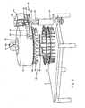
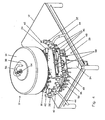
- a rotary filler is shown including many features known in the prior art and is generally indicated by reference numeral 10.
- the rotary filler 10 is supported on a table 12 and includes filling liquid supply means in the form of a reservoir 14 that is round in plan view, supported high above the table on reservoir support means in the form of a central post 16.
- Thirty two bottle filling valves 18 are attached to the underside of the reservoir 14 in a circumferentially spaced arrangement and are in flow communication with the cavity inside the reservoir.
- Each valve 18 has a discharge nozzle 20 at its lower end, that is connected by bellows 22 to the rest of the valve, so that the valve opens when the nozzle is moved upwards, relative to the rest of the valve.
- the valves 18 are so-called “level filling” valves that are well known in the art and that stop filling depending on liquid levels relative to the elevations of openings/passages.
- the nozzles of non-contact valves need to be cleaned inside and outside, similar to contact valves.
- each pedestal 24 is supported in a circular arrangement above the table 12 and each pedestal is vertically displaceable by a cam mechanism (not shown).
- the reservoir 14, valves 18 and pedestals 24 are connected together to rotate at the same rate and each pedestal is kept generally underneath one of the valves.
- Cleaning apparatus in accordance with the present invention is generally indicated by reference numeral 30 and includes two cip manifolds 32, each pivotally attached to support means in the form of an upright cylinder 34 extending from the table 12 and a crank assembly 36, at the top of the cylinder.
- the apparatus 30 also includes a cover 38 that is receivable in a top opening of the reservoir 14.
- Each manifold 32 includes an elongate, curved, hollow body 40 from which eight hollow spigots 42 extend upwardly, each defining a cleaning opening of the manifold.
- the spigots 42 are spaced apart in a curved configuration resembling the configuration of the valves 18 in that it has the same pitch diameter and the same spacing.
- a flexible hose 44 is attached to the body of each manifold at its one end, the other end being attachable to other equipment (see below).
- the internal cavity of the hollow body 40 is sealed, apart from being in flow communication with each of the spigots 42 and with the hose 44.
- pitch diameter refers to the diameter of an imaginary circle on which the centres of a number of articles is situated.
- the crank assembly 36 includes three horizontal plates 46, spaced above one another, with two crank mechanisms for the manifolds generally housed between the lower two plates and actuating crank cylinders 50 generally housed between the upper two plates.
- Each crank mechanism includes a cylindrical pivot bush 48 that can pivot about a vertical axis, and a crank arm (not shown) that is fixedly attached to the bush and is actuated by its associated cylinder 50 in crank fashion, to pivot the bush about its axis.
- Each bush 48 is fixedly attached to a pivot arm, which is attached to its associated manifold 32.
- the two crank assemblies are mirror images of each other and are configured to pivot the manifolds 32 between outer positions (shown in Figures 1 to 4 ) and inner positions (shown in Figures 5 to 8 ) in which the spigots 42 of both manifolds are positioned in a circumferential arrangement with a pitch radius of all the spigots generally equal to the common pitch radius of the valves 18 and the pedestals 24.
- the cover 38 is removably fitted in a sealing manner in the upper opening of the reservoir 14 on a slip ring of high density polyethylene (HDPE) and includes a central product inlet pipe 54 and a forked cip pipe assembly 56 with two spray balls (not shown) attached to it, inside the cavity of the reservoir.
- the product inlet pipe 54 is connectable to a supply of liquid with which bottles can be filled in the rotary filler 10, while the cip pipe assembly 56 is connectable to a supply or discharge of cleaning liquid (see below).
- Cylinder 34 is configured to move the crank assembly 36 and consequently the attached manifolds 32, vertically.
- a similar cylinder arrangement (not shown) is provided to move the reservoir 14 and attached valves 18 vertically. It is to be understood that the powered movements described herein with reference to cylinders, cranks, etc, can be achieved in other ways, without departing from the scope of the invention.
- the manifolds 32 are pivoted outwardly so that they can extend on the outside of the reservoir 14 and the cylinder 34 is extended to lift the manifolds to the position shown, next to the reservoir. In this position, the manifolds 32 are out of the way and the pedestals 24 and valves 18 are easily visible and accessible.
- the reservoir 14 and valves 18 When the reservoir 14 and valves 18 have been in use and need to be cleaned, the reservoir is emptied/drained and the pedestals 24 are cleared of any bottles.
- the manifolds 32 are lowered by the cylinder 34 to a position shown in Figures 3 and 4 , where the manifolds are at a height below the valves 18. At the same time, the reservoir 14 and valves 18 are lifted by the cylinder of the central post 16, to provide a large enough space to fit the manifolds between the valves and the pedestals 24. It is to be understood that, depending on the size and configuration of the rotary filler 10 and apparatus 30, it may be sufficient either to lift the reservoir 14 or to lower the manifolds 32. Further, it is possible to configure the pedestals 24 to be lowered, to provide space for the manifolds 32.
- the manifolds 32 are positioned underneath the valves 18 by pivoting them to their inner positions as shown in Figures 5 and 6 . If necessary, the reservoir 14 is rotated about its vertical axis until a valve 18 is aligned with the cleaning opening of each spigot 42.
- the manifolds 32 are lifted by the cylinder 34 so that the nozzle 20 of each of the valves 18 that is aligned with a spigot 42 is received within the spigot and is pushed upwardly so that the valve is opened and is in flow communication with the cleaning opening, as shown in Figures 7 and 8 .
- the reservoir 14 and valves 18 can be lowered relative to the manifolds..
- the reservoir 14 and valves 18 are cleaned by repeatedly rinsing them consecutively in an "upward” fashion and a “downward” fashion, with a cleaning liquid including diluents, solvents, detergents, and/or the like.
- the hoses 44 are connected to a supply of the cleaning liquid under pressure, so that the liquid flows under pressure into the cavities of the manifolds 32, around the nozzles 20, upwardly through the valves 18, including their vents (if any), and into the reservoir 14.
- the liquid is removed from the reservoir 14 via the cip pipe assembly 56.
- the cip pipe assembly 56 is connected to the supply of the cleaning liquid and the liquid is sprayed into the reservoir via the spray balls, from where it flows under gravity and/or pressure along a flow path opposite to that described in respect of upward rinsing, until it is drained out of the manifolds 32 via the hoses 44.
- the manifolds 32 are lowered and/or the reservoir and valves are lifted, to withdraw the nozzles 20 from the spigots 42, to the position shown in Figures 5 and 6 , the manifolds are pivoted outwardly to the position shown in Figures 3 and 4 , and are lifted to the position shown in Figures 1 and 2 , whereafter the rotary filler 10 can be returned to service.
- the manifolds 32 are configured to allow simultaneous cleaning of all the valves 18 of the particular rotary filler 10. Depending on the size of the rotary filler 10 and the number of valves, it may be necessary to provide more than one cylinder 34 and crank assembly 36, at different positions around the filler and/or to provide more pivoted or hinged manifolds 32.
- the invention illustrated holds the advantages of allowing a number of bottle filling valves to be cleaned simultaneously by rinsing from the overhead reservoir and/or from the cip manifold, without the need to handle the manifold and without significantly obstructing visibility or accessibility of the bottle filling process.
Landscapes
- Engineering & Computer Science (AREA)
- Mechanical Engineering (AREA)
- Filling Of Jars Or Cans And Processes For Cleaning And Sealing Jars (AREA)
Claims (15)
- Ein Verfahren zur Reinigung einer Rundläufer-Flaschenabfüllanlage (10), die eine Vielzahl von erhöhten, umlaufend verteilten Ventilen (18) beinhaltet, von denen jedes in Flüssigkeitsverbindung mit einem Füllflüssigkeitszufuhrmittel (14) steht, das einen erhöhten Vorratsbehälter (14) einschließt, wobei sich die Ventile (18) unterhalb des Vorratsbehälters (14) befinden, und wobei das Verfahren Folgendes umfasst:Bereitstellen einer Vielzahl von beabstandeten Hohlzapfen (42), die eine Vielzahl von Reinigungsöffnungen (42) definieren;Positionieren der Hohlzapfen (42) relativ zu den Ventilen (18), sodass die Hohlzapfen (42) sich in einer Höhe unterhalb der Höhe der Ventile (18) befinden;Positionieren der Hohlzapfen (42) unterhalb der Ventile (18), wobei sich jede Reinigungsöffnung (42) in Flüssigkeitsverbindung mit einem Ventil (18) befindet;Ausspülen von mindestens einigen der Ventile (18) mit Flüssigkeit, die durch das Füllflüssigkeitszufuhrmittel (14), die Ventile (18) und die Hohlzapfen (42) fließt; undAbnehmen der Hohlzapfen (42) von den Ventilen (18);worin die Hohlzapfen (42) einen Teil eines abgedichteten Sammelrohres (32) bilden und das Verfahren die Lagerung des Sammelrohres in einer gelagerten Position anschließend an die Anlage (10) in der Nähe des Vorratsbehälters (14) beinhaltet, in einer Position, die gute Sichtbarkeit und Zugang zu den Ventilen (18) ermöglicht, unddadurch gekennzeichnet, dass der Schritt der Positionierung des Sammelrohres (32) relativ zu den Ventilen (18) in einer Höhe unterhalb der Höhe der Ventile (18) das Herabsenken des Sammelrohres (32) von seiner gelagerten Position umfasst, und der Schritt der Positionierung des Sammelrohres (32) unterhalb der Ventile (18) das Schwenken des Sammelrohres (32) um eine aufrechte Achse von einer äußeren Position zu einer inneren Position umfasst, in der die Zapfen (42) unterhalb in einer umlaufenden Anordnung positioniert sind, wobei ein Teilkreisradius im Allgemeinen dem Teilkreisradius der Ventile entspricht.
- Ein Verfahren wie in Anspruch 1 beansprucht, dadurch gekennzeichnet, dass zwei der Sammelrohre (32) um aufrechte Achsen zwischen ihren äußeren Positionen und ihren inneren Positionen geschwenkt werden.
- Ein Verfahren wie in Anspruch 2 beansprucht, dadurch gekennzeichnet, dass jedes der genannten Sammelrohre (32) über einen Kurbelmechanismus zwischen seiner äußeren Position und seiner inneren Position geschwenkt wird, wobei die Baugruppen (36) gespiegelt sind.
- Ein Verfahren wie in einem der vorhergehenden Ansprüche beansprucht, dadurch gekennzeichnet, dass der Schritt des Positionierens des Sammelrohres (32) relativ zu den Ventilen (18) in einer Höhe unterhalb der Höhe der Ventile (18) das Anheben der Ventile (18)
- Ein Verfahren wie in Anspruch 4 beansprucht, dadurch gekennzeichnet, dass der Schritt des Anhebens der Ventile (18) das Anheben des Flüssigkeitszufuhrmittels (14) gemeinsam mit den Ventilen (18) beinhaltet.
- Ein Verfahren wie in einem der vorhergehenden Ansprüche beansprucht, dadurch gekennzeichnet, dass die Ventile (18) geöffnet werden, um eine Flüssigkeitskommunikation mit den Reinigungsöffnungen (42) zu erzielen, indem ein unterer Teil jedes Ventils (18) relativ zum übrigen Ventil (18) nach oben bewegt wird.
- Ein Verfahren wie in einem der vorhergehenden Ansprüche beansprucht, dadurch gekennzeichnet, dass die Ventile (18) geöffnet werden, indem das Sammelrohr (32) und die Ventile (18) vertikal näher zusammengebracht werden.
- Ein Verfahren wie in einem der vorhergehenden Ansprüche beansprucht, dadurch gekennzeichnet, dass die Ventile (18) mit Flüssigkeit, die vom Füllflüssigkeitszufuhrmittel (14) durch die Ventile (18) und in das Sammelrohr (32) fließt, gespült werden.
- Ein Verfahren wie in einem der Ansprüche 1-7 beansprucht, dadurch gekennzeichnet, dass die Ventile (18) mit Flüssigkeit, die von dem Sammelrohr (32) durch die Ventile (18) und in das Füllflüssigkeitszufuhrsystem (14) fließt, gespült werden.
- Ein Verfahren wie in einem der Ansprüche 1-7 beansprucht, dadurch gekennzeichnet, dass die Ventile (18) mit Flüssigkeit, die wiederholt hintereinander vom Sammelrohr (32) durch die Ventile (18) und in das Füllflüssigkeitszufuhrmittel (14) und danach in die entgegengesetzte Richtung fließt, gespült werden.
- Ein Verfahren wie in einem der vorhergehenden Ansprüche beansprucht, dadurch gekennzeichnet, dass das Verfahren das Zurückbefördern des Sammelrohres (32) in die gelagerte Position anschließend an die Flaschenabfüllanlage (10) umfasst.
- Vorrichtung (30) zur Reinigung einer Rundläufer-Flaschenabfüllanlage (10), wobei die Rundläufer-Flaschenabfüllanlage eine Vielzahl von erhöhten, umlaufend verteilten Ventilen (18) beinhaltet, von denen sich jedes in Flüssigkeitsverbindung mit einem Füllflüssigkeitszufuhrmittel (14) befindet, das einen erhöhten Vorratsbehälter (14) beinhaltet, wobei sich die Ventile (18) unterhalb des Vorratsbehälters (14) befinden, und wobei die Vorrichtung (30) Folgendes umfasst:eine Vielzahl von beabstandeten Hohlzapfen (42), die Reinigungsöffnungen (42) definieren, die in einer Anordnung beabstandet sind, welche der Anordnung der Ventile (18) gleicht;Abstützmittel (34, 36) zum Abstützen der Hohlzapfen (42);Mittel (34) zur Positionierung der Hohlzapfen (42) relativ zu den Ventilen (18), sodass die Hohlzapfen (42) sich in einer Höhe unterhalb der Höhe der Ventile (18) befinden;Mittel (36) zur Positionierung der Hohlzapfen (42) unterhalb der Ventile (18), wobei sich jede Reinigungsöffnung (42) in Flüssigkeitsverbindung mit einem Ventil (18) befindet; undMittel (44, 56) zur Zufuhr einer Reinigungsflüssigkeit zu mindestens einem der Hohlzapfen (42) und dem Füllflüssigkeitszufuhrmittel (14);worin die Hohlzapfen (42) einen Teil eines abgedichteten Sammelrohres (32) bilden und das Abstützmittel (34, 36) dazu dient, das Sammelrohr (32) in einer gelagerten Position anschließend an das Füllflüssigkeitszufuhrmittel (14) in der Nähe des Vorratsbehälters (14) in einer Stellung, welche gute Sichtbarkeit und Zugang zu den Ventilen (18) ermöglicht, abzustützen,dadurch gekennzeichnet, dass das Sammelrohr (32) schwenkbar auf seinem Abstützmittel (34, 36) anschließend an die Rundläufer-Flaschenabfüllanlage (10) getragen wird, sodass es um eine aufrechte Achse von einer Außenposition zu einer Innenposition geschwenkt wird, in der die Zapfen (42) unterhalb einer umlaufenden Anordnung positioniert sind, wobei ein Teilkreisradius im Allgemeinen dem Teilkreisradius der Ventile entspricht.
- Vorrichtung wie in Anspruch 12 beansprucht, dadurch gekennzeichnet, dass das Sammelrohrabstützmittel (34, 36) dazu dient, zwei der Sammelrohre (32) zu tragen, von denen jedes ausgeführt ist, um eines der Sammelrohre (32) um eine aufrechte Achse zwischen seinen Außenpositionen und seiner Innenposition zu schwenken.
- Vorrichtung wie in Anspruch 13 beansprucht, dadurch gekennzeichnet, dass jedes Sammelrohr (32) mit einen Kurbelmechanismus verbunden ist, sodass es zwischen seiner Außenposition und seiner Innenposition geschwenkt wird, und wobei die Sammelrohre gespiegelte Baugruppen beinhalten.
- Vorrichtung wie in einem der Ansprüche 12 bis 14 beansprucht, dadurch gekennzeichnet, dass das Sammelrohrabstützmittel (34, 36) und das Abstützmittel, das die Ventile (18) abstützt, dazu dienen, das Sammelrohr (32) und die Ventile (18) vertikal näher zusammenzubringen.
Applications Claiming Priority (2)
| Application Number | Priority Date | Filing Date | Title |
|---|---|---|---|
| ZA200506319 | 2005-08-08 | ||
| PCT/ZA2006/000012 WO2007019590A2 (en) | 2005-08-08 | 2006-01-25 | Method and apparatus for automated cleaning of bottling equipment |
Publications (3)
| Publication Number | Publication Date |
|---|---|
| EP1924368A2 EP1924368A2 (de) | 2008-05-28 |
| EP1924368A4 EP1924368A4 (de) | 2011-11-02 |
| EP1924368B1 true EP1924368B1 (de) | 2014-04-16 |
Family
ID=37728047
Family Applications (1)
| Application Number | Title | Priority Date | Filing Date |
|---|---|---|---|
| EP06721172.2A Expired - Lifetime EP1924368B1 (de) | 2005-08-08 | 2006-01-25 | Verfahren und vorrichtung zur automatisierten reinigung von flaschenfülleinrichtung |
Country Status (11)
| Country | Link |
|---|---|
| US (1) | US8002900B2 (de) |
| EP (1) | EP1924368B1 (de) |
| CN (1) | CN101631720B (de) |
| AU (1) | AU2006278243B2 (de) |
| BR (1) | BRPI0614271A2 (de) |
| CA (1) | CA2618714C (de) |
| IL (1) | IL189343A (de) |
| MX (1) | MX2008001930A (de) |
| RU (1) | RU2390393C2 (de) |
| WO (1) | WO2007019590A2 (de) |
| ZA (1) | ZA200803539B (de) |
Cited By (1)
| Publication number | Priority date | Publication date | Assignee | Title |
|---|---|---|---|---|
| RU2769014C1 (ru) * | 2021-04-14 | 2022-03-28 | Общество с ограниченной ответственностью НПО "Компания АВИС" | Аппарат автоматизированного розлива жидкостных продуктов в ёмкости |
Families Citing this family (24)
| Publication number | Priority date | Publication date | Assignee | Title |
|---|---|---|---|---|
| FR2899220B1 (fr) * | 2006-03-31 | 2008-05-30 | Sidel Participations | Dispositif de nettoyage pour machine de remplissage |
| DE102006038255B4 (de) * | 2006-08-16 | 2008-07-10 | Khs Ag | Verfahren und Vorrichtung zum Behandeln von Behältern |
| FR2911595B1 (fr) * | 2007-01-22 | 2011-04-08 | Sidel Participations | Machine de remplissage equipee d'un dispositif de nettoyage |
| US7850788B2 (en) * | 2007-08-20 | 2010-12-14 | Conagra Foods Rdm, Inc. | Clean in place gassing manifold |
| IT1395203B1 (it) * | 2009-08-19 | 2012-09-05 | Gruppo Bertolaso Spa | Macchina riempitrice rotativa di contenitori con liquidi |
| FR2950609B1 (fr) | 2009-09-29 | 2011-12-09 | Sidel Participations | Machine de remplissage equipee d'un dispositif de nettoyage en place a elements collecteurs individuels |
| ITMI20120296A1 (it) * | 2012-02-28 | 2013-08-29 | Ronchi Mario Spa | Apparecchiatura automatica per il recupero dei fluidi di lavaggio di macchine operatrici e macchina dotata di detta apparecchiatura |
| DE102012009206A1 (de) * | 2012-05-10 | 2013-11-14 | Khs Gmbh | Füllmaschine |
| DE102012019161A1 (de) | 2012-09-28 | 2014-04-03 | Khs Gmbh | Füllmaschine |
| DE202014105563U1 (de) * | 2014-11-19 | 2016-02-22 | Krones Aktiengesellschaft | Etikettiervorrichtung und Reinigungsvorrichtung für Zentrierglocken einer Etikettiervorrichtung |
| CN104923529B (zh) * | 2015-06-23 | 2017-01-11 | 曾妙玲 | 一种酒瓶清洗装置 |
| ITUB20152077A1 (it) * | 2015-07-10 | 2017-01-10 | Azionaria Costruzioni Acma Spa | Macchina riempitrice e metodo di riempimento di contenitori. |
| CN105502252B (zh) * | 2015-12-31 | 2018-06-15 | 杭州中亚机械股份有限公司 | 一种直线灌装装置 |
| CN105540513B (zh) * | 2015-12-31 | 2018-02-23 | 杭州中亚机械股份有限公司 | 一种直线灌装装置 |
| CN105436183B (zh) * | 2015-12-31 | 2017-08-15 | 杭州中亚机械股份有限公司 | 一种废液收集器 |
| CN105642636B (zh) * | 2015-12-31 | 2018-11-23 | 杭州中亚机械股份有限公司 | 一种废液收集器 |
| DE102017109873A1 (de) * | 2017-05-08 | 2018-11-08 | Haver & Boecker Ohg | Reinigungsvorrichtung zum Reinigen einer rohrförmigen Innenwand eines Behälters von Schüttgutpartikeln |
| CN108821218A (zh) * | 2018-07-10 | 2018-11-16 | 杨立撒 | 饮料灌装生产设备 |
| CN108821217A (zh) * | 2018-07-10 | 2018-11-16 | 杨立撒 | 瓶体清洗机构和饮料灌装设备 |
| CN109092834B (zh) * | 2018-07-30 | 2020-04-21 | 安徽佰瑞特日用品有限公司 | 一种保温瓶胆内腔喷洗装置 |
| CN110698063B (zh) * | 2019-11-23 | 2020-08-14 | 杭州更蓝生物科技有限公司 | 一种化妆品用玻璃瓶加工方法 |
| CN113083833B (zh) * | 2021-03-31 | 2023-11-10 | 湖北三得利塑料包装有限公司 | 一种塑料饮料瓶制作加工方法 |
| CN116765058B (zh) * | 2023-07-03 | 2025-05-16 | 龙口市通达油管有限公司 | 一种油管清洁工装及清洁装置及清洁方法 |
| CN117841916B (zh) * | 2024-03-08 | 2024-04-30 | 四川凯德源科技有限公司 | 固定转动轴的旋转洗车机及其控制系统 |
Family Cites Families (17)
| Publication number | Priority date | Publication date | Assignee | Title |
|---|---|---|---|---|
| SU466921A1 (ru) * | 1973-01-26 | 1975-04-15 | Ленинградское Областное Производственное Объединение Молочной Промышленности | Установка дл автоматической безразборной мойки оборудовани |
| US4024896A (en) * | 1975-05-13 | 1977-05-24 | Shibuya Kogyo Company, Ltd. | Washing device for rotary filling machine |
| US4414036A (en) * | 1981-09-18 | 1983-11-08 | Anderson Frank E | Sanitizer system and sanitizing method for carbonated beverage container filler machine |
| US4559961A (en) * | 1984-04-16 | 1985-12-24 | Anderson Frank E | Sanitizer system for beverage can filler machine |
| DE3722495C2 (de) | 1987-07-08 | 1994-04-07 | Holstein & Kappert Maschf | Füll- und Verschließmaschine für Gefäße |
| JPH0659915B2 (ja) * | 1988-07-21 | 1994-08-10 | エフ・エム・シー・コーポレーション | 充填機ノズルの清掃装置 |
| US4987934A (en) * | 1989-07-05 | 1991-01-29 | Fmc Corporation | Cleaner for filler nozzles |
| IT1234001B (it) * | 1989-07-21 | 1992-04-22 | Sarcmi Spa | Valvola di riempimento incorporante mezzi di supporto di una falsa bottiglia, per macchine riempitrici |
| JP2582559Y2 (ja) * | 1992-02-03 | 1998-10-08 | 四国化工機株式会社 | 充填機の洗浄装置 |
| DE4343425A1 (de) | 1993-12-18 | 1995-06-22 | Khs Masch & Anlagenbau Ag | Hubvorrichtung für eine Füllmaschine sowie Füllmaschine mit einer solchen Hubvorrichtung |
| DE9319866U1 (de) | 1993-12-23 | 1995-02-09 | Krones Ag Hermann Kronseder Maschinenfabrik, 93073 Neutraubling | Gefäßfüllmaschine |
| JP3454293B2 (ja) * | 1995-02-17 | 2003-10-06 | 澁谷工業株式会社 | 回転式充填装置の洗浄システム |
| JPH10338296A (ja) * | 1997-06-05 | 1998-12-22 | Shintaku Kogyo Kk | 液体充填機の充填ノズルの洗浄装置 |
| IT1293960B1 (it) * | 1997-06-20 | 1999-03-11 | Mbf Spa | Macchina riempitrice rotativa per il riempimento di contenitori con liquidi |
| JPH1191877A (ja) * | 1997-09-12 | 1999-04-06 | Toyo Shokuhin Kikai Kk | 充填バルブの洗浄装置 |
| JP3991135B2 (ja) | 1997-11-18 | 2007-10-17 | 澁谷工業株式会社 | 充填装置 |
| DE10030458B4 (de) | 2000-06-21 | 2009-12-31 | Robert Bosch Gmbh | Dosiervorrichtung für flüssige oder pastöse Produkte |
-
2006
- 2006-01-25 WO PCT/ZA2006/000012 patent/WO2007019590A2/en not_active Ceased
- 2006-01-25 AU AU2006278243A patent/AU2006278243B2/en not_active Ceased
- 2006-01-25 ZA ZA200803539A patent/ZA200803539B/xx unknown
- 2006-01-25 BR BRPI0614271-0A patent/BRPI0614271A2/pt not_active IP Right Cessation
- 2006-01-25 CN CN2006800365305A patent/CN101631720B/zh not_active Expired - Fee Related
- 2006-01-25 EP EP06721172.2A patent/EP1924368B1/de not_active Expired - Lifetime
- 2006-01-25 RU RU2008109808/12A patent/RU2390393C2/ru not_active IP Right Cessation
- 2006-01-25 MX MX2008001930A patent/MX2008001930A/es active IP Right Grant
- 2006-01-25 CA CA2618714A patent/CA2618714C/en not_active Expired - Fee Related
- 2006-01-25 US US12/063,112 patent/US8002900B2/en not_active Expired - Fee Related
-
2008
- 2008-02-07 IL IL189343A patent/IL189343A/en not_active IP Right Cessation
Cited By (1)
| Publication number | Priority date | Publication date | Assignee | Title |
|---|---|---|---|---|
| RU2769014C1 (ru) * | 2021-04-14 | 2022-03-28 | Общество с ограниченной ответственностью НПО "Компания АВИС" | Аппарат автоматизированного розлива жидкостных продуктов в ёмкости |
Also Published As
| Publication number | Publication date |
|---|---|
| WO2007019590A3 (en) | 2009-08-27 |
| CN101631720B (zh) | 2011-11-23 |
| EP1924368A4 (de) | 2011-11-02 |
| IL189343A0 (en) | 2008-11-03 |
| US20080302392A1 (en) | 2008-12-11 |
| MX2008001930A (es) | 2008-03-04 |
| ZA200803539B (en) | 2009-09-30 |
| CA2618714C (en) | 2013-11-05 |
| RU2008109808A (ru) | 2009-10-10 |
| RU2390393C2 (ru) | 2010-05-27 |
| US8002900B2 (en) | 2011-08-23 |
| BRPI0614271A2 (pt) | 2011-03-22 |
| AU2006278243A1 (en) | 2007-02-15 |
| IL189343A (en) | 2013-12-31 |
| EP1924368A2 (de) | 2008-05-28 |
| AU2006278243B2 (en) | 2010-12-16 |
| CN101631720A (zh) | 2010-01-20 |
| WO2007019590A2 (en) | 2007-02-15 |
| CA2618714A1 (en) | 2007-02-15 |
Similar Documents
| Publication | Publication Date | Title |
|---|---|---|
| EP1924368B1 (de) | Verfahren und vorrichtung zur automatisierten reinigung von flaschenfülleinrichtung | |
| US6026867A (en) | Rotary filling machine | |
| RU2369556C2 (ru) | Устройство для смены деталей, установленных на вращающихся машинах для обработки емкостей | |
| EP0018545A1 (de) | Vorrichtung zum Reinigen von Flaschen | |
| EP2103564B1 (de) | Reinigungsausrüstung für eine Flaschenabfüllmaschine | |
| US4534494A (en) | Cleaning system for filler | |
| US20060185755A1 (en) | Cleaning system for a filling machine | |
| US20150090365A1 (en) | Filling machine | |
| US2353519A (en) | Mechanism for charging containers | |
| US8151831B2 (en) | Carousel for processing containers filled with liquid or powder products | |
| WO2013136289A1 (en) | Cleaning arrangement and method of use | |
| EP1282583B1 (de) | Maschine zum befüllen von behäletrn mit einer flüssigen substanz | |
| RU2140870C1 (ru) | Разливочная машина | |
| KR20220040785A (ko) | 음료통 세척 장치 | |
| JP2002308385A (ja) | 充填機の洗浄装置 | |
| RU2048434C1 (ru) | Разливочная машина | |
| CN218317456U (zh) | 一种全自动药液灌装设备 | |
| EP0162480A2 (de) | Vorrichtung zum Ausgeben von flüssigen und zähflüssigen Materialien | |
| US20100032056A1 (en) | Rotary filling machine | |
| CA1167810A (en) | Variable volume, positive displacement sanitary liquid dispensing machine | |
| JP2912197B2 (ja) | 瓶洗浄装置の流体圧シリンダ | |
| JPH07112794A (ja) | ロータリー式液体充填機用液体排出装置 | |
| Wilson et al. | Modern Filling Systems for Carbonated Soft Drinks | |
| JPH07251899A (ja) | 操作体の着脱装置 | |
| JPH06255697A (ja) | 充填包装機用操作体の自動交換および収納装置 |
Legal Events
| Date | Code | Title | Description |
|---|---|---|---|
| PUAI | Public reference made under article 153(3) epc to a published international application that has entered the european phase |
Free format text: ORIGINAL CODE: 0009012 |
|
| 17P | Request for examination filed |
Effective date: 20080306 |
|
| AK | Designated contracting states |
Kind code of ref document: A2 Designated state(s): AT BE BG CH CY CZ DE DK EE ES FI FR GB GR HU IE IS IT LI LT LU LV MC NL PL PT RO SE SI SK TR |
|
| AX | Request for extension of the european patent |
Extension state: AL BA HR MK YU |
|
| R17D | Deferred search report published (corrected) |
Effective date: 20090827 |
|
| RIC1 | Information provided on ipc code assigned before grant |
Ipc: B65B 1/04 20060101AFI20090922BHEP |
|
| DAX | Request for extension of the european patent (deleted) | ||
| A4 | Supplementary search report drawn up and despatched |
Effective date: 20110929 |
|
| RIC1 | Information provided on ipc code assigned before grant |
Ipc: B08B 9/032 20060101AFI20110923BHEP Ipc: B67C 3/00 20060101ALI20110923BHEP |
|
| 17Q | First examination report despatched |
Effective date: 20120525 |
|
| REG | Reference to a national code |
Ref country code: DE Ref legal event code: R079 Ref document number: 602006041086 Country of ref document: DE Free format text: PREVIOUS MAIN CLASS: B08B0009080000 Ipc: B08B0009000000 |
|
| GRAP | Despatch of communication of intention to grant a patent |
Free format text: ORIGINAL CODE: EPIDOSNIGR1 |
|
| RIC1 | Information provided on ipc code assigned before grant |
Ipc: B08B 9/032 20060101ALI20131007BHEP Ipc: B67C 3/00 20060101ALI20131007BHEP Ipc: B08B 9/00 20060101AFI20131007BHEP |
|
| INTG | Intention to grant announced |
Effective date: 20131030 |
|
| GRAS | Grant fee paid |
Free format text: ORIGINAL CODE: EPIDOSNIGR3 |
|
| GRAA | (expected) grant |
Free format text: ORIGINAL CODE: 0009210 |
|
| AK | Designated contracting states |
Kind code of ref document: B1 Designated state(s): AT BE BG CH CY CZ DE DK EE ES FI FR GB GR HU IE IS IT LI LT LU LV MC NL PL PT RO SE SI SK TR |
|
| REG | Reference to a national code |
Ref country code: GB Ref legal event code: FG4D |
|
| REG | Reference to a national code |
Ref country code: CH Ref legal event code: EP |
|
| REG | Reference to a national code |
Ref country code: AT Ref legal event code: REF Ref document number: 662176 Country of ref document: AT Kind code of ref document: T Effective date: 20140515 |
|
| REG | Reference to a national code |
Ref country code: IE Ref legal event code: FG4D |
|
| REG | Reference to a national code |
Ref country code: DE Ref legal event code: R096 Ref document number: 602006041086 Country of ref document: DE Effective date: 20140522 |
|
| REG | Reference to a national code |
Ref country code: AT Ref legal event code: MK05 Ref document number: 662176 Country of ref document: AT Kind code of ref document: T Effective date: 20140416 |
|
| REG | Reference to a national code |
Ref country code: NL Ref legal event code: VDEP Effective date: 20140416 |
|
| REG | Reference to a national code |
Ref country code: LT Ref legal event code: MG4D |
|
| PG25 | Lapsed in a contracting state [announced via postgrant information from national office to epo] |
Ref country code: NL Free format text: LAPSE BECAUSE OF FAILURE TO SUBMIT A TRANSLATION OF THE DESCRIPTION OR TO PAY THE FEE WITHIN THE PRESCRIBED TIME-LIMIT Effective date: 20140416 Ref country code: LT Free format text: LAPSE BECAUSE OF FAILURE TO SUBMIT A TRANSLATION OF THE DESCRIPTION OR TO PAY THE FEE WITHIN THE PRESCRIBED TIME-LIMIT Effective date: 20140416 Ref country code: GR Free format text: LAPSE BECAUSE OF FAILURE TO SUBMIT A TRANSLATION OF THE DESCRIPTION OR TO PAY THE FEE WITHIN THE PRESCRIBED TIME-LIMIT Effective date: 20140717 Ref country code: CY Free format text: LAPSE BECAUSE OF FAILURE TO SUBMIT A TRANSLATION OF THE DESCRIPTION OR TO PAY THE FEE WITHIN THE PRESCRIBED TIME-LIMIT Effective date: 20140416 Ref country code: BG Free format text: LAPSE BECAUSE OF FAILURE TO SUBMIT A TRANSLATION OF THE DESCRIPTION OR TO PAY THE FEE WITHIN THE PRESCRIBED TIME-LIMIT Effective date: 20140716 Ref country code: FI Free format text: LAPSE BECAUSE OF FAILURE TO SUBMIT A TRANSLATION OF THE DESCRIPTION OR TO PAY THE FEE WITHIN THE PRESCRIBED TIME-LIMIT Effective date: 20140416 Ref country code: IS Free format text: LAPSE BECAUSE OF FAILURE TO SUBMIT A TRANSLATION OF THE DESCRIPTION OR TO PAY THE FEE WITHIN THE PRESCRIBED TIME-LIMIT Effective date: 20140816 |
|
| PG25 | Lapsed in a contracting state [announced via postgrant information from national office to epo] |
Ref country code: AT Free format text: LAPSE BECAUSE OF FAILURE TO SUBMIT A TRANSLATION OF THE DESCRIPTION OR TO PAY THE FEE WITHIN THE PRESCRIBED TIME-LIMIT Effective date: 20140416 Ref country code: LV Free format text: LAPSE BECAUSE OF FAILURE TO SUBMIT A TRANSLATION OF THE DESCRIPTION OR TO PAY THE FEE WITHIN THE PRESCRIBED TIME-LIMIT Effective date: 20140416 Ref country code: SE Free format text: LAPSE BECAUSE OF FAILURE TO SUBMIT A TRANSLATION OF THE DESCRIPTION OR TO PAY THE FEE WITHIN THE PRESCRIBED TIME-LIMIT Effective date: 20140416 Ref country code: PL Free format text: LAPSE BECAUSE OF FAILURE TO SUBMIT A TRANSLATION OF THE DESCRIPTION OR TO PAY THE FEE WITHIN THE PRESCRIBED TIME-LIMIT Effective date: 20140416 Ref country code: ES Free format text: LAPSE BECAUSE OF FAILURE TO SUBMIT A TRANSLATION OF THE DESCRIPTION OR TO PAY THE FEE WITHIN THE PRESCRIBED TIME-LIMIT Effective date: 20140416 |
|
| REG | Reference to a national code |
Ref country code: DE Ref legal event code: R097 Ref document number: 602006041086 Country of ref document: DE |
|
| PG25 | Lapsed in a contracting state [announced via postgrant information from national office to epo] |
Ref country code: CZ Free format text: LAPSE BECAUSE OF FAILURE TO SUBMIT A TRANSLATION OF THE DESCRIPTION OR TO PAY THE FEE WITHIN THE PRESCRIBED TIME-LIMIT Effective date: 20140416 Ref country code: BE Free format text: LAPSE BECAUSE OF FAILURE TO SUBMIT A TRANSLATION OF THE DESCRIPTION OR TO PAY THE FEE WITHIN THE PRESCRIBED TIME-LIMIT Effective date: 20140416 Ref country code: EE Free format text: LAPSE BECAUSE OF FAILURE TO SUBMIT A TRANSLATION OF THE DESCRIPTION OR TO PAY THE FEE WITHIN THE PRESCRIBED TIME-LIMIT Effective date: 20140416 Ref country code: SK Free format text: LAPSE BECAUSE OF FAILURE TO SUBMIT A TRANSLATION OF THE DESCRIPTION OR TO PAY THE FEE WITHIN THE PRESCRIBED TIME-LIMIT Effective date: 20140416 Ref country code: RO Free format text: LAPSE BECAUSE OF FAILURE TO SUBMIT A TRANSLATION OF THE DESCRIPTION OR TO PAY THE FEE WITHIN THE PRESCRIBED TIME-LIMIT Effective date: 20140416 Ref country code: DK Free format text: LAPSE BECAUSE OF FAILURE TO SUBMIT A TRANSLATION OF THE DESCRIPTION OR TO PAY THE FEE WITHIN THE PRESCRIBED TIME-LIMIT Effective date: 20140416 |
|
| PLBE | No opposition filed within time limit |
Free format text: ORIGINAL CODE: 0009261 |
|
| STAA | Information on the status of an ep patent application or granted ep patent |
Free format text: STATUS: NO OPPOSITION FILED WITHIN TIME LIMIT |
|
| 26N | No opposition filed |
Effective date: 20150119 |
|
| PG25 | Lapsed in a contracting state [announced via postgrant information from national office to epo] |
Ref country code: IT Free format text: LAPSE BECAUSE OF FAILURE TO SUBMIT A TRANSLATION OF THE DESCRIPTION OR TO PAY THE FEE WITHIN THE PRESCRIBED TIME-LIMIT Effective date: 20140416 |
|
| REG | Reference to a national code |
Ref country code: DE Ref legal event code: R097 Ref document number: 602006041086 Country of ref document: DE Effective date: 20150119 |
|
| PG25 | Lapsed in a contracting state [announced via postgrant information from national office to epo] |
Ref country code: SI Free format text: LAPSE BECAUSE OF FAILURE TO SUBMIT A TRANSLATION OF THE DESCRIPTION OR TO PAY THE FEE WITHIN THE PRESCRIBED TIME-LIMIT Effective date: 20140416 |
|
| REG | Reference to a national code |
Ref country code: DE Ref legal event code: R119 Ref document number: 602006041086 Country of ref document: DE |
|
| REG | Reference to a national code |
Ref country code: CH Ref legal event code: PL |
|
| PG25 | Lapsed in a contracting state [announced via postgrant information from national office to epo] |
Ref country code: LU Free format text: LAPSE BECAUSE OF FAILURE TO SUBMIT A TRANSLATION OF THE DESCRIPTION OR TO PAY THE FEE WITHIN THE PRESCRIBED TIME-LIMIT Effective date: 20150125 |
|
| GBPC | Gb: european patent ceased through non-payment of renewal fee |
Effective date: 20150125 |
|
| PG25 | Lapsed in a contracting state [announced via postgrant information from national office to epo] |
Ref country code: MC Free format text: LAPSE BECAUSE OF FAILURE TO SUBMIT A TRANSLATION OF THE DESCRIPTION OR TO PAY THE FEE WITHIN THE PRESCRIBED TIME-LIMIT Effective date: 20140416 |
|
| PG25 | Lapsed in a contracting state [announced via postgrant information from national office to epo] |
Ref country code: GB Free format text: LAPSE BECAUSE OF NON-PAYMENT OF DUE FEES Effective date: 20150125 Ref country code: DE Free format text: LAPSE BECAUSE OF NON-PAYMENT OF DUE FEES Effective date: 20150801 Ref country code: LI Free format text: LAPSE BECAUSE OF NON-PAYMENT OF DUE FEES Effective date: 20150131 Ref country code: CH Free format text: LAPSE BECAUSE OF NON-PAYMENT OF DUE FEES Effective date: 20150131 |
|
| REG | Reference to a national code |
Ref country code: FR Ref legal event code: ST Effective date: 20150930 |
|
| REG | Reference to a national code |
Ref country code: IE Ref legal event code: MM4A |
|
| PG25 | Lapsed in a contracting state [announced via postgrant information from national office to epo] |
Ref country code: FR Free format text: LAPSE BECAUSE OF NON-PAYMENT OF DUE FEES Effective date: 20150202 |
|
| PG25 | Lapsed in a contracting state [announced via postgrant information from national office to epo] |
Ref country code: IE Free format text: LAPSE BECAUSE OF NON-PAYMENT OF DUE FEES Effective date: 20150125 |
|
| PG25 | Lapsed in a contracting state [announced via postgrant information from national office to epo] |
Ref country code: HU Free format text: LAPSE BECAUSE OF FAILURE TO SUBMIT A TRANSLATION OF THE DESCRIPTION OR TO PAY THE FEE WITHIN THE PRESCRIBED TIME-LIMIT; INVALID AB INITIO Effective date: 20060125 |
|
| PG25 | Lapsed in a contracting state [announced via postgrant information from national office to epo] |
Ref country code: PT Free format text: LAPSE BECAUSE OF FAILURE TO SUBMIT A TRANSLATION OF THE DESCRIPTION OR TO PAY THE FEE WITHIN THE PRESCRIBED TIME-LIMIT Effective date: 20140816 |
|
| PG25 | Lapsed in a contracting state [announced via postgrant information from national office to epo] |
Ref country code: TR Free format text: LAPSE BECAUSE OF FAILURE TO SUBMIT A TRANSLATION OF THE DESCRIPTION OR TO PAY THE FEE WITHIN THE PRESCRIBED TIME-LIMIT Effective date: 20140416 |