EP1927431A1 - Temperature control method and device of machine tool - Google Patents
Temperature control method and device of machine tool Download PDFInfo
- Publication number
- EP1927431A1 EP1927431A1 EP06781798A EP06781798A EP1927431A1 EP 1927431 A1 EP1927431 A1 EP 1927431A1 EP 06781798 A EP06781798 A EP 06781798A EP 06781798 A EP06781798 A EP 06781798A EP 1927431 A1 EP1927431 A1 EP 1927431A1
- Authority
- EP
- European Patent Office
- Prior art keywords
- temperature
- control
- refrigerator
- flow rate
- opening degree
- Prior art date
- Legal status (The legal status is an assumption and is not a legal conclusion. Google has not performed a legal analysis and makes no representation as to the accuracy of the status listed.)
- Granted
Links
Images

Classifications
-
- F—MECHANICAL ENGINEERING; LIGHTING; HEATING; WEAPONS; BLASTING
- F25—REFRIGERATION OR COOLING; COMBINED HEATING AND REFRIGERATION SYSTEMS; HEAT PUMP SYSTEMS; MANUFACTURE OR STORAGE OF ICE; LIQUEFACTION SOLIDIFICATION OF GASES
- F25B—REFRIGERATION MACHINES, PLANTS OR SYSTEMS; COMBINED HEATING AND REFRIGERATION SYSTEMS; HEAT PUMP SYSTEMS
- F25B49/00—Arrangement or mounting of control or safety devices
- F25B49/02—Arrangement or mounting of control or safety devices for compression type machines, plants or systems
- F25B49/025—Motor control arrangements
-
- B—PERFORMING OPERATIONS; TRANSPORTING
- B23—MACHINE TOOLS; METAL-WORKING NOT OTHERWISE PROVIDED FOR
- B23Q—DETAILS, COMPONENTS, OR ACCESSORIES FOR MACHINE TOOLS, e.g. ARRANGEMENTS FOR COPYING OR CONTROLLING; MACHINE TOOLS IN GENERAL CHARACTERISED BY THE CONSTRUCTION OF PARTICULAR DETAILS OR COMPONENTS; COMBINATIONS OR ASSOCIATIONS OF METAL-WORKING MACHINES, NOT DIRECTED TO A PARTICULAR RESULT
- B23Q11/00—Accessories fitted to machine tools for keeping tools or parts of the machine in good working condition or for cooling work; Safety devices specially combined with or arranged in, or specially adapted for use in connection with, machine tools
- B23Q11/14—Methods or arrangements for maintaining a constant temperature in parts of machine tools
- B23Q11/141—Methods or arrangements for maintaining a constant temperature in parts of machine tools using a closed fluid circuit for cooling or heating
-
- F—MECHANICAL ENGINEERING; LIGHTING; HEATING; WEAPONS; BLASTING
- F25—REFRIGERATION OR COOLING; COMBINED HEATING AND REFRIGERATION SYSTEMS; HEAT PUMP SYSTEMS; MANUFACTURE OR STORAGE OF ICE; LIQUEFACTION SOLIDIFICATION OF GASES
- F25B—REFRIGERATION MACHINES, PLANTS OR SYSTEMS; COMBINED HEATING AND REFRIGERATION SYSTEMS; HEAT PUMP SYSTEMS
- F25B2400/00—Component parts or details not otherwise provided for in this subclass
- F25B2400/04—Refrigeration circuit bypassing means
- F25B2400/0403—Refrigeration circuit bypassing means for condensers
-
- F—MECHANICAL ENGINEERING; LIGHTING; HEATING; WEAPONS; BLASTING
- F25—REFRIGERATION OR COOLING; COMBINED HEATING AND REFRIGERATION SYSTEMS; HEAT PUMP SYSTEMS; MANUFACTURE OR STORAGE OF ICE; LIQUEFACTION SOLIDIFICATION OF GASES
- F25B—REFRIGERATION MACHINES, PLANTS OR SYSTEMS; COMBINED HEATING AND REFRIGERATION SYSTEMS; HEAT PUMP SYSTEMS
- F25B2600/00—Control issues
- F25B2600/02—Compressor control
- F25B2600/021—Inverters therefor
-
- F—MECHANICAL ENGINEERING; LIGHTING; HEATING; WEAPONS; BLASTING
- F25—REFRIGERATION OR COOLING; COMBINED HEATING AND REFRIGERATION SYSTEMS; HEAT PUMP SYSTEMS; MANUFACTURE OR STORAGE OF ICE; LIQUEFACTION SOLIDIFICATION OF GASES
- F25B—REFRIGERATION MACHINES, PLANTS OR SYSTEMS; COMBINED HEATING AND REFRIGERATION SYSTEMS; HEAT PUMP SYSTEMS
- F25B2600/00—Control issues
- F25B2600/25—Control of valves
- F25B2600/2501—Bypass valves
-
- F—MECHANICAL ENGINEERING; LIGHTING; HEATING; WEAPONS; BLASTING
- F25—REFRIGERATION OR COOLING; COMBINED HEATING AND REFRIGERATION SYSTEMS; HEAT PUMP SYSTEMS; MANUFACTURE OR STORAGE OF ICE; LIQUEFACTION SOLIDIFICATION OF GASES
- F25B—REFRIGERATION MACHINES, PLANTS OR SYSTEMS; COMBINED HEATING AND REFRIGERATION SYSTEMS; HEAT PUMP SYSTEMS
- F25B2600/00—Control issues
- F25B2600/25—Control of valves
- F25B2600/2513—Expansion valves
-
- F—MECHANICAL ENGINEERING; LIGHTING; HEATING; WEAPONS; BLASTING
- F25—REFRIGERATION OR COOLING; COMBINED HEATING AND REFRIGERATION SYSTEMS; HEAT PUMP SYSTEMS; MANUFACTURE OR STORAGE OF ICE; LIQUEFACTION SOLIDIFICATION OF GASES
- F25B—REFRIGERATION MACHINES, PLANTS OR SYSTEMS; COMBINED HEATING AND REFRIGERATION SYSTEMS; HEAT PUMP SYSTEMS
- F25B2700/00—Sensing or detecting of parameters; Sensors therefor
- F25B2700/21—Temperatures
- F25B2700/2117—Temperatures of an evaporator
- F25B2700/21171—Temperatures of an evaporator of the fluid cooled by the evaporator
- F25B2700/21172—Temperatures of an evaporator of the fluid cooled by the evaporator at the inlet
Definitions
- the present invention relates to a temperature control method and device for machine tools for cooling a heating source of a machine tool and suppressing thermal deformation, and more particularly to a temperature control method and device which can decrease transient deviation between a setting temperature and a coolant temperature, and can decrease time until the coolant temperature stabilizes (settling time) in the temperature control of machine tools, even if the calorific value of the heating source changes.
- the body of a machine tool could be deformed by environmental temperature.and heat from a heating section. Since deformation of the body affects processing accuracy, conventionally the temperature of each section of the body has been controlled to be a predetermined temperature.
- Various methods have been proposed to control the temperature, but normally a cooling oil, of which temperature is controlled, is constantly supplied to a heating section of a machine tool at a predetermined flow rate, so as to cool down the heating section.
- This cooling oil is cooled by a coolant gas via a heat exchanger.
- the setting temperature of the cooling oil is a room temperature or a temperature of an element of which time constant is at the maximum among the composing elements of the machine tool, and the temperature of the cooling oil at the outlet of the heating section of the machine tool is controlled to follow up with this temperature.
- This method minimizes the thermal deformation of the machine tool and decreases processing errors.
- This method is a known technology, and these systems are called "room temperature follow up control" or "body temperature follow up control”.
- a two-position control (ON-OFF control) has been used as the simplest control operation for such a room temperature follow up control or body temperature follow up control.
- the cooling temperature to be controlled has a temperature change width.
- the oil temperature to be controlled generates a steady state deviation.
- the temperature change width and the steady state deviation may exceed the tolerance. Therefore control to eliminate the steady state deviation is sometimes performed by PID control, including integration operations.
- Another proposal is smoothing the change of coolant temperature by controlling the change of rotation speed of a refrigerator, which is a compressor, by the driving frequency of an inverter.
- the rotation speed of a main spindle of a machine tool changes from stopping status to several thousand times per minute or more, and the width of the calorific value is very large, so conventional inverter frequency control alone causes control problems due to the limit in variable range of the cooling capability.
- the variable range of cooling capacity is about 1:4 (ratio of minimum frequency and maximum frequency).
- the limit of variable range of cooling capability in the low load are (including no load)
- the accuracy of temperature control in the low load area deteriorates.
- Patent Document 1 discloses a temperature control method for machine tools which decreases the transient deviation and the steady state deviation by feed forward control, wherein a bypass line, which bypasses the coolant gas immediately after coming out of the refrigerator, is created, and the variable range of cooling capability in the low load area is expanded by opening an electrostatic valve created on the bypass line.
- Patent Document 1 Even the technology of Patent Document 1 has the following problems. First an interface circuit to send rotation speed instruction information on a main spindle of a machine tool to a temperature control device is required, since control is performed based on feed forward control, and software for sending the rotation speed instruction information is also required, so the system of the machine tool side must be changed, system development takes time, and the cost of the entire system increases. Also it is necessary to create a control table to store the relationships between the rotation speed of the main spindle of the machine tool and the cooling capability of the refrigerator as a data base, in order to perform feed forward control, and the creation of this control table also increases the time and cost of system development.
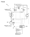
- Fig. 4 is a diagram depicting a configuration of a temperature control device 1a in the case when a temperature control similar to Patent Document 1 is performed only by feedback control.
- a spindle head is used as an example of a typical heating source of a machine tool.
- a main spindle is rotatably supported, and a tool or work piece is mounted to the main spindle and is rotary driven. Since the rotation speed of the main spindle of the machine tool changes from the stopping state to several thousand rotations per minute, temperature control is performed by cooling the spindle head which supports the main spindle, so that the temperature of the spindle head always maintains a predetermined temperature difference with respect to a reference temperature.
- the control target is always maintaining the temperature of the spindle head to have a predetermined temperature difference with respect to the reference temperature.
- the reference temperature is set to a room temperature or a temperature of an element (e.g. bed, column) having a large time constant (having a large thermal capacity) out of the composing elements of the machine tool.
- the temperature of the reference element which is measured by a reference temperature sensor 13, is set as the reference temperature.
- one temperature may be selected out of the temperatures measured at a plurality of locations, or an average value of a plurality of measured values may be used.
- the reference temperature may also be set by performing an appropriate computation on measured values.
- a cooling circuit 2 is created so as to cool the spindle head of the machine tool, and a cooling oil as a coolant circulates in the cooling circuit 2.
- a cooling pump 22, installed in the cooling circuit 2 is driven by a driving motor 23, and circulates the cooling oil in the cooling circuit 2 at a predetermined flow rate. After being cooled by a heat exchanger 8, the cooling oil is supplied to the spindle head, and cools the spindle head.
- the coolant gas For the coolant which flows into the heat exchanger 8, the coolant gas is first compressed by a refrigerator 5, and is then sent to a condenser 6.
- the heat of the coolant gas, of which temperature was increased by compression, is radiated, and the gas is liquefied.
- the condenser 6 is cooled by air cooling using a cooling fan 61.
- the liquefied coolant gas is throttle-expanded while passing through an expansion valve 7, and becomes a low temperature low pressure gas-liquid mixed state.
- This low temperature low pressure gas-liquid mixed coolant gas flows into the heat exchanger 8, and cools the cooling oil.
- the coolant gas is evaporated in the heat exchanger 8 by receiving the heat of the cooling oil, and efficiently cools the cooling oil by the heat of vaporization.
- the coolant gas flowing from the heat exchanger 8 returns to the refrigerator 5, and circulates through a circulation circuit 3.
- the refrigerator 5 is driven by an inverter, and the rotation speed of the refrigerator 5 can be changed by changing the driving frequency.
- the driving frequency of the refrigerator 5 is controlled by a temperature control section 10a. Specific details of the temperature control section 10a will be described later.
- a bypass line 4 which supplies a part of the coolant gas, of which temperature was increased by compression, into the heat exchanger 8 without cooling, is attached to the circulation circuit 3 through which the coolant gas circulates.
- An electromagnetic switching valve 41 is disposed in the bypass line 4.
- the bypass line 4 is disposed for adjusting the cooling capability to cool the cooling oil, and when the electromagnetic switching valve 41 is in an open state, high temperature gas mixes with the low temperature coolant gas, and flows into the heat exchanger 8, so the cooling capability drops.
- the electromagnetic switching valve 41 is in a closed state, the high temperature gas does not mix in, and the default capability of the refrigerator 5 is active.
- the temperature control section 10a controls the temperature of the spindle head of the machine tool by controlling the driving frequency of the refrigerator 5, the open/closed state of the electromagnetic switching valve 41, and the opening degree of the expansion valve 7.
- a display section 11 and an input section 12 are connected to the temperature control section 10a. Various parameters on the temperature control can be confirmed by the display section 11, and these parameters can be input by the input section 12.
- the temperature of the cooling oil, which cooled the spindle head and returned is detected by the temperature sensor 21, and this detected value is regarded as the typical temperature value of the spindle head.
- the opening degree of the valve is adjusted by moving the valve element by stepping motor driving. Therefore the opening degree of the expansion valve 7 can be adjusted by a digital opening degree instruction.
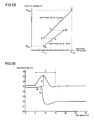
- Fig. 5 is a graph depicting a control state of the temperature control section 10a.
- the abscissa of the graph in Fig. 5 indicates the inverter frequency for driving the refrigerator 5, and the ordinate indicates the cooling capability of the temperature control device 1a. Since the rotation speed of the main spindle of the machine tool changes in a wide range, the change of the calorific value is also great, hence the temperature control section 10a must perform smooth control throughout a wide range from a low cooling capability range to a high cooling capability range.
- the driving frequency of the refrigerator 5, based on inverter driving alone has a limitation in controlling the cooling capability over a wide range. Therefore in this temperature control device 1a, the bypass line 4, for supplying a part of the coolant gas which is not cooled into the heat exchanger 8, is attached.
- the electromagnetic switching valve 41 If the electromagnetic switching valve 41 is opened, the high temperature gas from the bypass line 4 is mixed with the low temperature coolant gas, and flows into the heat exchanger 8, so the cooling capability drops. This is a control of the low cooling range, and becomes a control curve indicated by the line UVW in Fig. 5 .
- the change of the inverter frequency is controlled from the minimum value F min to the value corresponding to the point W. In this case, the cooling capability is changed from the minimum value Q min to the value corresponding to the point W.
- the control in a normal range is the control curve indicated by the line XYZ in Fig. 5 .
- the change of the inverter frequency is controlled from the minimum value F min to the maximum value F max .
- the cooling capability changes from the value corresponding to the point X to the maximum value Q max .
- the control range of the cooling capability is from the value corresponding to the point X to the maximum value Q max , but by adding the control of the low cooling range, the control range of the cooling capability is expanded.
- the lower limit of the cooling capability extends down to the minimum value Q min .
- the temperature control starts from the point U. If the calorific value gradually increases, the temperature control moves on the line UVW from the point U to the point W. If the temperature of the spindle head continuously increases, even after reaching the point W, the control curve shifts from the line UVW in the low cooling range to the line XYZ in the normal range. In other words, the electromagnetic switching valve 41 is closed, and the inverter frequency is dropped to the value corresponding to the point Y. If the calorific value continuously increases thereafter, the temperature control moves on the line XYZ from the point Y to the point Z.
- the temperature control moves on the line XYZ from the point Z to the point X. If the temperature of the spindle head continuously decreases even after reaching the point X, the control curve shifts from the line XYZ in the normal range to the line UVW in the low cooling range. In other words, the electromagnetic switching valve 41 is opened, and the inverter frequency is increased to a value corresponding to the point V. If the calorific value continuously decreases after this, the temperature control moves on the line UVW from the point V to the point U.
- Fig. 6 is a graph depicting a response at the change of the calorific value according to the temperature control method by the temperature control device 1a in Fig. 4 .
- the abscissa indicates an elapsed time [minutes], and the ordinate indicates a temperature [°C] of the cooling oil.
- the upper side curve indicates the temperature of the cooling oil returned after cooling the spindle head (return oil temperature), and is a temperature detected by the temperature sensor 21.
- the lower side curve indicates the temperature of the cooling oil which is cooled by the heat exchanger 8, and is supplied to the spindle head (supply oil temperature).
- the setting temperature of the return oil in the feedback control is 25°C.
- the main spindle is driven at a 200W driving power from time 0 to 5 minutes, and is driven at a 1500W driving power after 5 minutes has elapsed.
- the control state moves on the line UVW up to the point W, and then moves from the point W to the point Y, but in order to stably perform movement in this discontinuous control state, a predetermined standby time is provided by a timer before moving to the point Y. Without this standby time, discontinuous control state movement (switching of the electromagnetic switching value 41) occurs frequently, and control becomes unstable.
- the point M to the point N in the supply oil temperature graph is the standby time based on the timer, during which the supply oil temperature rises slightly. At the point N, the electromagnetic switching value 41 is closed, and control in the normal range is started.
- a temperature control method for machine tools is a temperature control method for a machine tool which has: a spindle head which has a rotatable main spindle and generates heat when the main spindle is rotary driven; a cooling circuit for circulating a coolant for cooling the spindle head; a refrigerator for compressing a coolant gas; a condenser for liquefying the coolant gas compressed by the refrigerator by radiating heat; an expansion valve for throttle-expanding the liquefied coolant gas; a heat exchanger for cooling the coolant by the coolant gas which is throttle-expanded and is in a low pressure and low temperature gas-liquid mixed state; a bypass line for supplying the coolant gas immediately after being output from the refrigerator to the heat exchanger bypassing the condenser; a bypass flow rate adjustment valve formed in the middle of the bypass line; a reference temperature setting means for setting a reference temperature; a temperature sensor for detecting a return liquid temperature, which is
- the temperature control means performs control according to the first control procedure in an area where the calorific value of the spindle head is small, and performs the control according to the second control procedure in an area where the calorific value of the spindle head is large, and switches the first control procedure and the second control procedure continuously.
- the opening degree of the bypass flow rate adjustment valve in the first control procedure is controlled by PID control.
- the rotation speed of the refrigerator in the second control procedure is controlled by PID control, and the expansion valve in the second control procedure controls the opening degree to a degree which corresponds to the rotation speed of the refrigerator on a one-to-one basis.
- the opening degree of the expansion valve and the bypass flow rate adjustment valve can be controlled by digital values.
- the refrigerator changes the rotation speed by the driving frequency of the inverter.
- a temperature control device for machine tools of the present invention comprises: a cooling circuit for circulating a coolant for cooling a spindle head of a machine tool; a refrigerator for compressing coolant gas; a condenser for liquefying the coolant gas compressed by the refrigerator by radiating heat; an expansion valve for throttle-expanding the liquefied coolant gas; a heat exchanger for cooling the coolant by the coolant gas which is throttle-expanded and is in a low pressure and low temperature gas-liquid mixed state; a bypass line for supplying the coolant gas immediately after being output from the refrigerator to the heat exchanger bypassing the condenser; a bypass flow rate adjustment valve formed in the middle of the bypass line; a reference temperature setting means for setting a reference temperature; a temperature sensor for detecting a return liquid temperature, which is a temperature of the coolant after cooling the spindle head; and temperature control means which adjusts the flow rate of the coolant gas to the heat exchanger by controlling the rotation speed of the refrigerator and the opening degree of the
- the temperature control means executes a first control procedure for setting the rotation speed of the refrigerator to a predetermined lower limit value, setting the opening degree of the expansion valve to a predetermined value corresponding to the rotation speed of the refrigerator, and performing feedback control on the opening degree of the bypass flow rate adjustment valve so that a temperature difference between the return liquid temperature detected by the temperature sensor and the reference temperature becomes constant, and a second control procedure for fully closing the bypass flow rate adjustment valve and performing feedback control on the rotation speed of the refrigerator and the opening degree of the expansion valve so that the temperature difference between the return liquid temperature detected by the temperature sensor and the reference temperature becomes constant.
- the temperature control means performs control according to the first control procedure in an area where the calorific value of the spindle head is small, and performs control according to the second control procedure in an area where the calorific value of the spindle head is large, and switches the first control procedure and the second control procedure continuously.
- the opening degree of the bypass flow rate adjustment valve in the first control procedure is controlled by PID control.
- the rotation speed of the refrigerator in the second control procedure is controlled by PID control, and the expansion valve in the second control procedure controls the opening degree to a degree which corresponds to the rotation speed of the refrigerator on a one-to-one basis.
- the opening degree of the expansion valve and the bypass flow rate adjustment valve can be controlled by digital values.
- the refrigerator changes the rotation speed by the driving frequency of the inverter.
- the temperature control is performed only by feedback control, the interface circuit, software and control table for feed forward control are not required, therefore time and cost for system development can be dramatically decreased. Hence the cost of a temperature control device can also be decreased. Even if the temperature control is performed only by feedback control, the control accuracy and the response characteristics in the shift between modes can be improved.
- the temperature control means continuously switches between the first control procedure and the second control procedure, so the modes of the first control procedure and the second control procedure can also be quickly and smoothly shifted. As a result, the accuracy of the temperature control and the response characteristics improve.
- the opening degree of the expansion valve is controlled to be a value which corresponds to the rotation speed of the refrigerator on a one-to-one basis, so the control mechanism is simplified and high-speed response becomes possible.
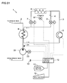
- Fig. 1 is a diagram depicting a configuration of a temperature control device 1 of the present invention.
- a spindle head is used as an example of a typical heating source of a machine tool.
- a main spindle is rotatably supported to the spindle head, and a tool or work piece is mounted to the main spindle and is rotary driven. Since the rotation speed of the main spindle of the machine tool changes from stopping state to several thousand rotations per minute, temperature control is performed by cooling the spindle head which supports the main spindle, so that the temperature of the spindle head always maintains a predetermined temperature difference with respect to a reference temperature. In other words, the control target is always maintaining the temperature of the spindle head to have a predetermined temperature difference with respect to the reference temperature.
- the reference temperature is set to a room temperature or a temperature of an element (e.g. bed, column) having a large time constant (having a large thermal capacity) out of the composing elements of the machine tool, as mentioned above.
- the temperature of the reference element which is measured by a reference temperature sensor 13, is set as the reference temperature.
- one temperature may be selected out of the temperatures measured at a plurality of locations, or an average value of a plurality of measured values may be used.
- the reference temperature may also be set by performing an appropriate computation on the measured values.
- a cooling circuit 2 is created so as to cool the spindle head of the machine tool, and a cooling oil, as a coolant, circulates in the cooling circuit 2.
- a cooling pump 22 installed in the cooling circuit 2 is driven by a driving motor 23, and circulates the cooling oil in the cooling circuit 2 at a predetermined flow rate.
- the cooling oil After being cooled by a heat exchanger 8, the cooling oil is supplied to the spindle head, and cools the spindle head.
- the cooling oil after cooling the spindle head, circulates through the cooling circuit 2 and returns to the cooling pump 22.
- a temperature of the cooling oil after cooling the spindle head (return oil temperature) is detected by a temperature sensor 21, and feedback control is performed so that the return oil temperature becomes a setting temperature.
- the setting temperature is set to a value which has a predetermined temperature difference from the reference temperature.
- the temperature difference may be 0, and in this case, the setting temperature is the same as the reference temperature.
- the position of the temperature sensor 21 is not limited to the position shown in Fig. 1 , but may be any position as long as the return oil temperature can be detected.
- [the temperature sensor 21] may be disposed at the in flow side of the cooling pump 22.
- the coolant gas is first compressed by a refrigerator 5 and is then sent to a condenser 6.
- the heat of the coolant gas, of which temperature was increased by compression is radiated and the gas is liquefied.
- the condenser 6 is cooled by air cooling using a cooling fan 61.
- the liquefied coolant gas is throttle-expanded while passing through an expansion valve 7, and becomes a low temperature low pressure gas-liquid mixed state.
- This low temperature low pressure gas-liquid mixed coolant gas flows into the heat exchanger 8, and cools the cooling oil.
- the coolant gas is evaporated in the heat exchanger 8 by receiving the heat of the cooling oil, and efficiently cools the cooling oil by the heat of vaporization.
- the coolant gas flowing from the heat exchanger 8 returns to the refrigerator 5, and circulates through a circulation circuit 3.
- the refrigerator 5 is driven by an inverter, and the rotation speed of the refrigerator 5 can be changed by changing the driving frequency. Because of this, the cooling capability of the temperature control device 1 can be changed and controlled.
- the driving frequency of the refrigerator 5 is controlled by a temperature control section 10. Specific details of the control of the temperature control section 10 will be described later.
- bypass line 4 In the circulation circuit 3 through which the coolant gas circulates, a bypass line 4 is attached, and this bypass line 4 supplies a part of the coolant gas, of which temperature was increased by compression, into the heat exchanger 8 without cooling.
- a bypass flow rate adjustment valve 9 In the bypass line 4, a bypass flow rate adjustment valve 9 is installed.
- the bypass line 4 is disposed in order to adjust a decrease in the cooling capability for cooling the cooling oil.
- the bypass flow rate adjustment valve 9 When the bypass flow rate adjustment valve 9 is in open state, the high temperature gas mixes into the low temperature coolant gas, and flows into the heat exchanger 8, so the cooling capability drops.
- the change in the cooling capability can be controlled (low cooling mode).
- the bypass flow rate adjustment valve 9 When the bypass flow rate adjustment valve 9 is in full closed state, the high temperature gas does not mix in, and the default cooling capability (normal cooling mode) of the refrigerator 5 is active.
- the temperature control section 10 controls the driving frequency of the refrigerator 5, the opening degree of the expansion valve 7, and the opening degree of the bypass flow rate adjustment valve 9 to control the temperature of the spindle head of the machine tool.
- a display section 11 and an input section 12 are connected to the temperature control section 10. Various parameters on temperature control can be confirmed by the display section 11, and these parameters can be input by the input section 12.
- the temperature of the cooling oil which cooled the spindle head and returned (return oil temperature)
- this detected value is regarded as the typical temperature value of the spindle head. Feedback control is performed so that this return oil temperature becomes the setting temperature.
- the feedback control is performed at high precision, high-speed response and high stability by PID control.
- the change of the opening degree of the bypass flow rate adjustment valve 9 is controlled by PID control
- a change in the inverter frequency to drive the refrigerator 5 is controlled by PID control for feedback control.
- the opening degree of the expansion valve 7 is fixed to a predetermined value corresponding to the inverter frequency to drive the refrigerator 5 in low cooling mode, or is changed interlocking with the inverter frequency for the refrigerator 5 in normal cooling mode.
- the opening degree y of the expansion valve 7 is controlled so as to correspond with the inverter frequency x for driving the refrigerator 5 on a one-to-one basis.
- a and b are constants.
- Constants a and b are set to appropriate values according to the capacity and characteristics of the refrigerator 5.
- the expansion valve 7 and the bypass flow rate adjustment valve 9 move the value element by stepping motor driving, so as to adjust the opening degree of the value. Therefore the opening degree of the valve can be adjusted by a digital opening degree instruction respectively.
- Fig. 2 is a graph depicting a control state of the temperature control method by the temperature control device 1 of the present invention.
- the abscissa of the graph in Fig. 2 indicates the inverter frequency for driving the refrigerator 5, and the ordinate indicates the cooling capability of the temperature control device 1.
- the left portion from the minimum value F min in the abscissa of the graph in Fig. 2 indicates the opening degree of the bypass flow rate adjustment valve 9. Since the rotation speed of the main spindle of the machine tool changes in a wide range, the change of the calorific value is also great, and the temperature control section 10 must perform a smooth control throughout the wide range, from low cooling capability to high cooling capability.
- controlling the cooling capability through a wide range has limitations if only the driving frequency of an inverter for driving the refrigerator 5 is used. Therefore in this temperature control device 1, the bypass line 4, for supplying a part of the coolant gas which is not cooled into the heat exchanger 8, is attached.
- the bypass flow rate adjustment valve 9 If the bypass flow rate adjustment valve 9 is opened, the high temperature gas from the bypass line 4 mixes with the low temperature coolant gas and flows into the heat exchanger 8, so the cooling capability drops.
- the change of the opening degree of the bypass flow rate adjustment valve 9 By controlling the change of the cooling capability can be controlled. This is the control in the low cooling mode, which is indicated by the control curve shown by line AB in Fig. 2 .
- the inverter frequency for driving the refrigerator 5 is maintained at the minimum value F min .
- the cooling capability changes from the minimum value Q min to the value corresponding to the point B.
- the bypass flow rate adjustment valve 9 is closed, the high temperature gas does not mix in, so the default cooling capability of the refrigerator 5 is active.
- the change of the cooling capability can be controlled. This is the control in the normal cooling mode, which is indicated by the control curve shown by line BC in Fig. 2 .
- the change of the inverter frequency is controlled from the minimum value F min to the maximum value F max .
- the cooling capability changes from a point corresponding to the point B to the maximum value Q max .
- the control range of the cooling capability is in the range from the value corresponding to the point B to the maximum value Q max if only control in the normal cooling mode is used, but the controlling range of the cooling capability is expanded by adding control in the low cooling mode.
- the lower limit of the cooling capability extends down to the minimum value Q min .
- the control curve of the low cooling mode and the control curve of the normal cooling mode are continuous at the point B, as shown in Fig. 2 , so the transition between these modes can be smooth. In other words, it is unnecessary to set a predetermined standby time when a range is shifted to another range, as shown in the control in Fig. 5 . In this way, according to the temperature control device 1 of the present invention, modes can be shifted quickly.
- the control in the low cooling mode (line AB) corresponds to the first control procedure in the Claims
- the control in the normal cooling mode corresponds to the second control procedure in the Claims.
- the temperature control starts from the point A.
- the bypass flow rate adjustment valve 9 is fully open, and the inverter frequency is at the minimum value F min .
- the bypass flow rate adjustment valve 9 is gradually closed, and the temperature control moves on the line AB from point A to point B.
- the bypass flow rate adjustment valve 9 becomes fully closed (inverter frequency is at minimum value F min ). If the temperature of the spindle head continuously increases even after reaching the point B, the control curve shifts from the line AB in the low cooling mode to the line BC in the normal cooling mode.
- bypass flow rate adjustment valve 9 is maintained in a fully closed state, and the change of the inverter frequency is controlled from the minimum value F min to the maximum value F max . If the calorific value increases, the temperature control moves on the line BC from the point B to the point C.
- the temperature control moves on the lien BC from the point C to the point B. If the temperature of the spindle head continuously decreases even after reaching the point B, the control curve shifts from the line BC in the normal cooling mode to the line AB in the low cooling mode. In other words, the inverter frequency is maintained at the minimum value F min , and the change of the opening degree of the bypass flow rate adjustment valve 9 is controlled. If the calorific value continuously decreases after this, the temperature control moves on the line AB from the point B to the point A.
- Fig. 3 is a graph depicting the response at the change of the calorific value according to the temperature control method by the temperature control device 1 of the present invention.
- the abscissa indicates the elapsed time [minutes] and the ordinate indicates the temperature [°C] of the cooling oil.
- the upper side curve indicates the return oil temperature detected by the temperature sensor 21.
- the lower side curve indicates the temperature of the cooling oil, which is cooled by the heat exchanger 8 and is supplied to the spindle head (supply oil temperature). This setting temperature of the return oil in the feedback control is 25°C.
- the main spindle is driven at 200W driving power from time 0 to 5 minutes, and is driven at 1500W driving power after 5 minutes has elapsed.
- the control state moves on the line AB up to the point B, and then shifts to the line BC.
- the shift from the line AB in the low cooling mode to the line BC in the normal cooling mode can be quick and smooth.
- the standby time, due to the shift between modes, is unnecessary, so the response when the calorific value changes improves.
- the settling time T s time until the return oil temperature stabilizes
- the transient deviation D transient deviation between the setting temperature and return oil temperature
- response characteristics, when modes are shifted, can be improved even if temperature is controlled only by feedback control. Since the temperature is controlled only by feedback control, the interface circuit, software and control table required for feed forward control are unnecessary, and time and cost of system development can be dramatically decreased. By this, the cost of the temperature control device can also be decreased.
- the cooling oil is used as an example of the coolant for cooling the spindle head of machine tools, but a cooling other than cooling oil may be used.
- a cooling other than cooling oil may be used.
- the case of cooling the spindle head of machine tools was described, but [the present invention] can also be applied to the case of cooling other heating elements.
- a temperature control method and device for a machine tool where the response characteristic when the calorific value of the heating source of the machine tool changed is improved, can be provided, and the cost of the temperature control device can also be decreased.
Landscapes
- Engineering & Computer Science (AREA)
- Mechanical Engineering (AREA)
- Physics & Mathematics (AREA)
- Thermal Sciences (AREA)
- General Engineering & Computer Science (AREA)
- Auxiliary Devices For Machine Tools (AREA)
- Automatic Control Of Machine Tools (AREA)
Abstract
Description
- The present invention relates to a temperature control method and device for machine tools for cooling a heating source of a machine tool and suppressing thermal deformation, and more particularly to a temperature control method and device which can decrease transient deviation between a setting temperature and a coolant temperature, and can decrease time until the coolant temperature stabilizes (settling time) in the temperature control of machine tools, even if the calorific value of the heating source changes.
- The body of a machine tool could be deformed by environmental temperature.and heat from a heating section. Since deformation of the body affects processing accuracy, conventionally the temperature of each section of the body has been controlled to be a predetermined temperature. Various methods have been proposed to control the temperature, but normally a cooling oil, of which temperature is controlled, is constantly supplied to a heating section of a machine tool at a predetermined flow rate, so as to cool down the heating section. This cooling oil is cooled by a coolant gas via a heat exchanger. The setting temperature of the cooling oil is a room temperature or a temperature of an element of which time constant is at the maximum among the composing elements of the machine tool, and the temperature of the cooling oil at the outlet of the heating section of the machine tool is controlled to follow up with this temperature. This method minimizes the thermal deformation of the machine tool and decreases processing errors. This method is a known technology, and these systems are called "room temperature follow up control" or "body temperature follow up control".
- A two-position control (ON-OFF control) has been used as the simplest control operation for such a room temperature follow up control or body temperature follow up control. In the case of two-position control, the cooling temperature to be controlled has a temperature change width. Also in the two-position control, the oil temperature to be controlled generates a steady state deviation. In the case of recent machine tools which have high calorific values, the temperature change width and the steady state deviation may exceed the tolerance. Therefore control to eliminate the steady state deviation is sometimes performed by PID control, including integration operations.
- Another proposal is smoothing the change of coolant temperature by controlling the change of rotation speed of a refrigerator, which is a compressor, by the driving frequency of an inverter. However, the rotation speed of a main spindle of a machine tool changes from stopping status to several thousand times per minute or more, and the width of the calorific value is very large, so conventional inverter frequency control alone causes control problems due to the limit in variable range of the cooling capability. Due to the restriction in a performance of a refrigerator, the variable range of cooling capacity is about 1:4 (ratio of minimum frequency and maximum frequency). Particularly because of the limit of variable range of cooling capability in the low load are (including no load), the accuracy of temperature control in the low load area deteriorates.
- In order to improve the accuracy of such conventional temperature control, the present applicant has proposed a technology disclosed in the following
Patent Document 1.Patent Document 1 discloses a temperature control method for machine tools which decreases the transient deviation and the steady state deviation by feed forward control, wherein a bypass line, which bypasses the coolant gas immediately after coming out of the refrigerator, is created, and the variable range of cooling capability in the low load area is expanded by opening an electrostatic valve created on the bypass line. - However, even the technology of
Patent Document 1 has the following problems. First an interface circuit to send rotation speed instruction information on a main spindle of a machine tool to a temperature control device is required, since control is performed based on feed forward control, and software for sending the rotation speed instruction information is also required, so the system of the machine tool side must be changed, system development takes time, and the cost of the entire system increases. Also it is necessary to create a control table to store the relationships between the rotation speed of the main spindle of the machine tool and the cooling capability of the refrigerator as a data base, in order to perform feed forward control, and the creation of this control table also increases the time and cost of system development. - It is possible to perform temperature control only by feedback control without performing feed forward control in order to decrease the cost of the technology of
Patent Document 1, but it became clear that the response deteriorates when the calorific value of the heating section changes (when the thermal load changes) in this case. This point will be described in detail. -
Fig. 4 is a diagram depicting a configuration of atemperature control device 1a in the case when a temperature control similar toPatent Document 1 is performed only by feedback control. In this description, a spindle head is used as an example of a typical heating source of a machine tool. To the spindle head, a main spindle is rotatably supported, and a tool or work piece is mounted to the main spindle and is rotary driven. Since the rotation speed of the main spindle of the machine tool changes from the stopping state to several thousand rotations per minute, temperature control is performed by cooling the spindle head which supports the main spindle, so that the temperature of the spindle head always maintains a predetermined temperature difference with respect to a reference temperature. In other words, the control target is always maintaining the temperature of the spindle head to have a predetermined temperature difference with respect to the reference temperature. - The reference temperature is set to a room temperature or a temperature of an element (e.g. bed, column) having a large time constant (having a large thermal capacity) out of the composing elements of the machine tool. The temperature of the reference element, which is measured by a
reference temperature sensor 13, is set as the reference temperature. For the reference temperature, one temperature may be selected out of the temperatures measured at a plurality of locations, or an average value of a plurality of measured values may be used. The reference temperature may also be set by performing an appropriate computation on measured values. - In
Fig. 4 , acooling circuit 2 is created so as to cool the spindle head of the machine tool, and a cooling oil as a coolant circulates in thecooling circuit 2. Acooling pump 22, installed in thecooling circuit 2, is driven by a drivingmotor 23, and circulates the cooling oil in thecooling circuit 2 at a predetermined flow rate. After being cooled by aheat exchanger 8, the cooling oil is supplied to the spindle head, and cools the spindle head. - For the coolant which flows into the
heat exchanger 8, the coolant gas is first compressed by arefrigerator 5, and is then sent to acondenser 6. In thecondenser 6, the heat of the coolant gas, of which temperature was increased by compression, is radiated, and the gas is liquefied. Thecondenser 6 is cooled by air cooling using acooling fan 61. The liquefied coolant gas is throttle-expanded while passing through anexpansion valve 7, and becomes a low temperature low pressure gas-liquid mixed state. This low temperature low pressure gas-liquid mixed coolant gas flows into theheat exchanger 8, and cools the cooling oil. The coolant gas is evaporated in theheat exchanger 8 by receiving the heat of the cooling oil, and efficiently cools the cooling oil by the heat of vaporization. The coolant gas flowing from theheat exchanger 8 returns to therefrigerator 5, and circulates through acirculation circuit 3. - The
refrigerator 5 is driven by an inverter, and the rotation speed of therefrigerator 5 can be changed by changing the driving frequency. The driving frequency of therefrigerator 5 is controlled by atemperature control section 10a. Specific details of thetemperature control section 10a will be described later. - A
bypass line 4, which supplies a part of the coolant gas, of which temperature was increased by compression, into theheat exchanger 8 without cooling, is attached to thecirculation circuit 3 through which the coolant gas circulates. Anelectromagnetic switching valve 41 is disposed in thebypass line 4. Thebypass line 4 is disposed for adjusting the cooling capability to cool the cooling oil, and when theelectromagnetic switching valve 41 is in an open state, high temperature gas mixes with the low temperature coolant gas, and flows into theheat exchanger 8, so the cooling capability drops. When theelectromagnetic switching valve 41 is in a closed state, the high temperature gas does not mix in, and the default capability of therefrigerator 5 is active. - The
temperature control section 10a controls the temperature of the spindle head of the machine tool by controlling the driving frequency of therefrigerator 5, the open/closed state of theelectromagnetic switching valve 41, and the opening degree of theexpansion valve 7. Adisplay section 11 and aninput section 12 are connected to thetemperature control section 10a. Various parameters on the temperature control can be confirmed by thedisplay section 11, and these parameters can be input by theinput section 12. For the temperature of the spindle head, the temperature of the cooling oil, which cooled the spindle head and returned, is detected by thetemperature sensor 21, and this detected value is regarded as the typical temperature value of the spindle head. In theexpansion valve 7, the opening degree of the valve is adjusted by moving the valve element by stepping motor driving. Therefore the opening degree of theexpansion valve 7 can be adjusted by a digital opening degree instruction. -
Fig. 5 is a graph depicting a control state of thetemperature control section 10a. The abscissa of the graph inFig. 5 indicates the inverter frequency for driving therefrigerator 5, and the ordinate indicates the cooling capability of thetemperature control device 1a. Since the rotation speed of the main spindle of the machine tool changes in a wide range, the change of the calorific value is also great, hence thetemperature control section 10a must perform smooth control throughout a wide range from a low cooling capability range to a high cooling capability range. However, as mentioned above, the driving frequency of therefrigerator 5, based on inverter driving alone, has a limitation in controlling the cooling capability over a wide range. Therefore in thistemperature control device 1a, thebypass line 4, for supplying a part of the coolant gas which is not cooled into theheat exchanger 8, is attached. - If the
electromagnetic switching valve 41 is opened, the high temperature gas from thebypass line 4 is mixed with the low temperature coolant gas, and flows into theheat exchanger 8, so the cooling capability drops. This is a control of the low cooling range, and becomes a control curve indicated by the line UVW inFig. 5 . The change of the inverter frequency is controlled from the minimum value Fmin to the value corresponding to the point W. In this case, the cooling capability is changed from the minimum value Qmin to the value corresponding to the point W. - If the
electromagnetic switching value 41 is closed, the high temperature gas does not mix in, so the default cooling capability of therefrigerator 5 is active. This is the control in a normal range, and is the control curve indicated by the line XYZ inFig. 5 . The change of the inverter frequency is controlled from the minimum value Fmin to the maximum value Fmax. In this case, the cooling capability changes from the value corresponding to the point X to the maximum value Qmax. In this way, in the case of control only in the normal range, the control range of the cooling capability is from the value corresponding to the point X to the maximum value Qmax, but by adding the control of the low cooling range, the control range of the cooling capability is expanded. In particular, the lower limit of the cooling capability extends down to the minimum value Qmin. - In the case of low heat load, such as when the rotation speed of the main spindle of the machine tool is low, the temperature control starts from the point U. If the calorific value gradually increases, the temperature control moves on the line UVW from the point U to the point W. If the temperature of the spindle head continuously increases, even after reaching the point W, the control curve shifts from the line UVW in the low cooling range to the line XYZ in the normal range. In other words, the
electromagnetic switching valve 41 is closed, and the inverter frequency is dropped to the value corresponding to the point Y. If the calorific value continuously increases thereafter, the temperature control moves on the line XYZ from the point Y to the point Z. - If the calorific value decreases from the point Z, the temperature control moves on the line XYZ from the point Z to the point X. If the temperature of the spindle head continuously decreases even after reaching the point X, the control curve shifts from the line XYZ in the normal range to the line UVW in the low cooling range. In other words, the
electromagnetic switching valve 41 is opened, and the inverter frequency is increased to a value corresponding to the point V. If the calorific value continuously decreases after this, the temperature control moves on the line UVW from the point V to the point U. -
Fig. 6 is a graph depicting a response at the change of the calorific value according to the temperature control method by thetemperature control device 1a inFig. 4 . The abscissa indicates an elapsed time [minutes], and the ordinate indicates a temperature [°C] of the cooling oil. The upper side curve indicates the temperature of the cooling oil returned after cooling the spindle head (return oil temperature), and is a temperature detected by thetemperature sensor 21. The lower side curve indicates the temperature of the cooling oil which is cooled by theheat exchanger 8, and is supplied to the spindle head (supply oil temperature). The setting temperature of the return oil in the feedback control is 25°C. - In
Fig. 6 , the main spindle is driven at a 200W driving power fromtime 0 to 5 minutes, and is driven at a 1500W driving power after 5 minutes has elapsed. In this case, in the control curve inFig. 5 , the control state moves on the line UVW up to the point W, and then moves from the point W to the point Y, but in order to stably perform movement in this discontinuous control state, a predetermined standby time is provided by a timer before moving to the point Y. Without this standby time, discontinuous control state movement (switching of the electromagnetic switching value 41) occurs frequently, and control becomes unstable. InFig. 6 , the point M to the point N in the supply oil temperature graph is the standby time based on the timer, during which the supply oil temperature rises slightly. At the point N, theelectromagnetic switching value 41 is closed, and control in the normal range is started. - As described above, if temperature control only of feedback control is performed by the
temperature control device 1a, the time until the return oil temperature stabilizes (settling time) becomes relatively long when the calorific value of the spindle head changes. InFig. 6 , the settling time Ts is about 10 minutes. The transient deviation (D inFig. 6 ) between the setting temperature and the return oil temperature also increases. InFig. 6 , the transient deviation D is 2.2°C.
Patent Document 1: Patent No. 2529905 - According to the conventional temperature control, control accuracy is insufficient to keep the processing accuracy of a machine tool high, and even the technology of
Patent Document 1, whereby the accuracy of the temperature control has been improved, has problems, that is the development of a system takes time, and the cost of the entire system increases. - Even if temperature control is performed only by feedback control using the
temperature control device 1a inFig. 4 , a problem is that the settling time Ts becomes long, and the transient deviation D increases when the calorific value of the spindle head changes. - With the foregoing in view, it is an object of the present invention to provide a temperature control method and device for a machine tool which can decrease a transient deviation between the setting temperature and the coolant temperature, and can decrease the time until the coolant temperature stabilizes (settling time), even if the calorific value of a heating source of the machine tool changes.
- To achieve the above objects, a temperature control method for machine tools according to the present invention is a temperature control method for a machine tool which has: a spindle head which has a rotatable main spindle and generates heat when the main spindle is rotary driven; a cooling circuit for circulating a coolant for cooling the spindle head; a refrigerator for compressing a coolant gas; a condenser for liquefying the coolant gas compressed by the refrigerator by radiating heat; an expansion valve for throttle-expanding the liquefied coolant gas; a heat exchanger for cooling the coolant by the coolant gas which is throttle-expanded and is in a low pressure and low temperature gas-liquid mixed state; a bypass line for supplying the coolant gas immediately after being output from the refrigerator to the heat exchanger bypassing the condenser; a bypass flow rate adjustment valve formed in the middle of the bypass line; a reference temperature setting means for setting a reference temperature; a temperature sensor for detecting a return liquid temperature, which is a temperature of the coolant after cooling the spindle head; and temperature control means which adjusts the flow rate of the coolant gas to the heat exchanger by controlling the rotation speed of the refrigerator and the opening degree of the expansion valve, and adjusts the flow rate of the coolant gas passing through the bypass line by controlling the bypass flow rate adjustment valve, the temperature control method comprising: a first control procedure for the temperature control means to set the rotation speed of the refrigerator to a predetermined lower limit value and to set the opening degree of the expansion valve to a predetermined value corresponding to the rotation speed of the refrigerator, and to perform feedback control on the opening degree of the bypass flow rate adjustment valve so that a temperature difference between the return liquid temperature detected by the temperature sensor and the reference temperature becomes constant; and a second control procedure for the temperature control means to fully close the bypass flow rate adjustment valve and to perform feedback control on the rotation speed of the refrigerator and the opening degree of the expansion valve so that the temperature difference between the return liquid temperature detected by the temperature sensor and the reference temperature becomes constant.
- In the above mentioned temperature control method for machine tools, it is preferable that the temperature control means performs control according to the first control procedure in an area where the calorific value of the spindle head is small, and performs the control according to the second control procedure in an area where the calorific value of the spindle head is large, and switches the first control procedure and the second control procedure continuously.
- In the above, mentioned temperature control method for machine tools, it is preferable that the opening degree of the bypass flow rate adjustment valve in the first control procedure is controlled by PID control.
- In the above mentioned temperature control method for machine tools, it is preferable that the rotation speed of the refrigerator in the second control procedure is controlled by PID control, and the expansion valve in the second control procedure controls the opening degree to a degree which corresponds to the rotation speed of the refrigerator on a one-to-one basis.
- In the above mentioned temperature control method for machine tools, it is preferable that the opening degree of the expansion valve and the bypass flow rate adjustment valve can be controlled by digital values.
- In the above mentioned temperature control method for machine tools, it is preferable that the refrigerator changes the rotation speed by the driving frequency of the inverter.
- A temperature control device for machine tools of the present invention, comprises: a cooling circuit for circulating a coolant for cooling a spindle head of a machine tool; a refrigerator for compressing coolant gas; a condenser for liquefying the coolant gas compressed by the refrigerator by radiating heat; an expansion valve for throttle-expanding the liquefied coolant gas; a heat exchanger for cooling the coolant by the coolant gas which is throttle-expanded and is in a low pressure and low temperature gas-liquid mixed state; a bypass line for supplying the coolant gas immediately after being output from the refrigerator to the heat exchanger bypassing the condenser; a bypass flow rate adjustment valve formed in the middle of the bypass line; a reference temperature setting means for setting a reference temperature; a temperature sensor for detecting a return liquid temperature, which is a temperature of the coolant after cooling the spindle head; and temperature control means which adjusts the flow rate of the coolant gas to the heat exchanger by controlling the rotation speed of the refrigerator and the opening degree of the expansion valve, and adjusts the flow rate of the coolant gas passing through the bypass line by controlling the bypass flow rate adjustment valve. The temperature control means executes a first control procedure for setting the rotation speed of the refrigerator to a predetermined lower limit value, setting the opening degree of the expansion valve to a predetermined value corresponding to the rotation speed of the refrigerator, and performing feedback control on the opening degree of the bypass flow rate adjustment valve so that a temperature difference between the return liquid temperature detected by the temperature sensor and the reference temperature becomes constant, and a second control procedure for fully closing the bypass flow rate adjustment valve and performing feedback control on the rotation speed of the refrigerator and the opening degree of the expansion valve so that the temperature difference between the return liquid temperature detected by the temperature sensor and the reference temperature becomes constant.
- In the above mentioned temperature control device for machine tools, it is preferable that the temperature control means performs control according to the first control procedure in an area where the calorific value of the spindle head is small, and performs control according to the second control procedure in an area where the calorific value of the spindle head is large, and switches the first control procedure and the second control procedure continuously.
- In the above mentioned temperature control device for machine tools, it is preferable that the opening degree of the bypass flow rate adjustment valve in the first control procedure is controlled by PID control.
- In the above mentioned temperature control device for machine tools, it is preferable that the rotation speed of the refrigerator in the second control procedure is controlled by PID control, and the expansion valve in the second control procedure controls the opening degree to a degree which corresponds to the rotation speed of the refrigerator on a one-to-one basis.
- In the above mentioned temperature control device for machine tools, it is preferable that the opening degree of the expansion valve and the bypass flow rate adjustment valve can be controlled by digital values.
- In the above mentioned temperature control device for machine tools, it is preferable that the refrigerator changes the rotation speed by the driving frequency of the inverter.
- Since the present invention has the above mentioned configuration, the following effects are exhibited.
- Because the temperature control is performed only by feedback control, the interface circuit, software and control table for feed forward control are not required, therefore time and cost for system development can be dramatically decreased. Hence the cost of a temperature control device can also be decreased. Even if the temperature control is performed only by feedback control, the control accuracy and the response characteristics in the shift between modes can be improved.
- The temperature control means continuously switches between the first control procedure and the second control procedure, so the modes of the first control procedure and the second control procedure can also be quickly and smoothly shifted. As a result, the accuracy of the temperature control and the response characteristics improve.
- Since the opening degree of the bypass flow rate adjustment valve is controlled by PID control, high accuracy, high-speed response and high stability control are possible.
- Since the rotation speed of the refrigerator is controlled by PID control, high accuracy, high-speed response and high stability control are possible. The opening degree of the expansion valve is controlled to be a value which corresponds to the rotation speed of the refrigerator on a one-to-one basis, so the control mechanism is simplified and high-speed response becomes possible.
- Since the opening degree of the expansion valve and the bypass flow rate adjustment valve can be controlled by digital values, high accuracy opening degree control becomes possible.
- Since the rotation speed of the refrigerator is changed by the driving frequency of the inverter, the change of the cooling capability can be smoothly controlled, and unnecessary energy consumption can also be decreased.
-
-
Fig. 1 is a diagram depicting a configuration of atemperature control device 1 of the present invention; -
Fig. 2 is a graph depicting a control state of a temperature control method of the present invention; -
Fig. 3 is a graph depicting a response when a calorific value is changed according to the temperature control method of the present invention; -
Fig. 4 is a diagram depicting a configuration of aconventional control device 1a; -
Fig. 5 is a graph depicting a control state of atemperature control section 10a; and -
Fig. 6 is a graph depicting a response when the calorific value is changed according to a temperature control method by thetemperature control device 1a inFig. 4 . -
- 1
- temperature control device
- 2
- cooling circuit
- 3
- circulation circuit
- 4
- bypass line
- 5
- refrigerator
- 6
- condenser
- 7
- expansion valve
- 8
- heat exchanger
- 9
- bypass flow rate adjustment valve
- 10
- temperature control section
- 11
- display section
- 12
- input section
- 13
- reference temperature sensor
- 21
- temperature sensor
- 22
- cooling pump
- 23
- driving motor
- 41
- electromagnetic switching valve
- 61
- cooling fan
- Embodiments of the present invention will now be described with reference to the drawings.
Fig. 1 is a diagram depicting a configuration of atemperature control device 1 of the present invention. In this description, a spindle head is used as an example of a typical heating source of a machine tool. A main spindle is rotatably supported to the spindle head, and a tool or work piece is mounted to the main spindle and is rotary driven. Since the rotation speed of the main spindle of the machine tool changes from stopping state to several thousand rotations per minute, temperature control is performed by cooling the spindle head which supports the main spindle, so that the temperature of the spindle head always maintains a predetermined temperature difference with respect to a reference temperature. In other words, the control target is always maintaining the temperature of the spindle head to have a predetermined temperature difference with respect to the reference temperature. - The reference temperature is set to a room temperature or a temperature of an element (e.g. bed, column) having a large time constant (having a large thermal capacity) out of the composing elements of the machine tool, as mentioned above. The temperature of the reference element, which is measured by a
reference temperature sensor 13, is set as the reference temperature. For the reference temperature, one temperature may be selected out of the temperatures measured at a plurality of locations, or an average value of a plurality of measured values may be used. The reference temperature may also be set by performing an appropriate computation on the measured values. - In
Fig. 1 , acooling circuit 2 is created so as to cool the spindle head of the machine tool, and a cooling oil, as a coolant, circulates in thecooling circuit 2. A coolingpump 22 installed in thecooling circuit 2 is driven by a drivingmotor 23, and circulates the cooling oil in thecooling circuit 2 at a predetermined flow rate. After being cooled by aheat exchanger 8, the cooling oil is supplied to the spindle head, and cools the spindle head. The cooling oil, after cooling the spindle head, circulates through thecooling circuit 2 and returns to thecooling pump 22. A temperature of the cooling oil after cooling the spindle head (return oil temperature) is detected by atemperature sensor 21, and feedback control is performed so that the return oil temperature becomes a setting temperature. The setting temperature is set to a value which has a predetermined temperature difference from the reference temperature. The temperature difference may be 0, and in this case, the setting temperature is the same as the reference temperature. The position of thetemperature sensor 21 is not limited to the position shown inFig. 1 , but may be any position as long as the return oil temperature can be detected. For example, [the temperature sensor 21] may be disposed at the in flow side of thecooling pump 22. - For the coolant which flows into the
heat exchanger 8, on the other hand, the coolant gas is first compressed by arefrigerator 5 and is then sent to acondenser 6. In thecondenser 6, the heat of the coolant gas, of which temperature was increased by compression, is radiated and the gas is liquefied. Thecondenser 6 is cooled by air cooling using a coolingfan 61. The liquefied coolant gas is throttle-expanded while passing through anexpansion valve 7, and becomes a low temperature low pressure gas-liquid mixed state. This low temperature low pressure gas-liquid mixed coolant gas flows into theheat exchanger 8, and cools the cooling oil. The coolant gas is evaporated in theheat exchanger 8 by receiving the heat of the cooling oil, and efficiently cools the cooling oil by the heat of vaporization. The coolant gas flowing from theheat exchanger 8 returns to therefrigerator 5, and circulates through acirculation circuit 3. - The
refrigerator 5 is driven by an inverter, and the rotation speed of therefrigerator 5 can be changed by changing the driving frequency. Because of this, the cooling capability of thetemperature control device 1 can be changed and controlled. The driving frequency of therefrigerator 5 is controlled by atemperature control section 10. Specific details of the control of thetemperature control section 10 will be described later. - In the
circulation circuit 3 through which the coolant gas circulates, abypass line 4 is attached, and thisbypass line 4 supplies a part of the coolant gas, of which temperature was increased by compression, into theheat exchanger 8 without cooling. In thebypass line 4, a bypass flow rate adjustment valve 9 is installed. Thebypass line 4 is disposed in order to adjust a decrease in the cooling capability for cooling the cooling oil. When the bypass flow rate adjustment valve 9 is in open state, the high temperature gas mixes into the low temperature coolant gas, and flows into theheat exchanger 8, so the cooling capability drops. By controlling the change in the opening degree of the bypass flow rate adjustment valve 9, the change in the cooling capability can be controlled (low cooling mode). When the bypass flow rate adjustment valve 9 is in full closed state, the high temperature gas does not mix in, and the default cooling capability (normal cooling mode) of therefrigerator 5 is active. - The
temperature control section 10 controls the driving frequency of therefrigerator 5, the opening degree of theexpansion valve 7, and the opening degree of the bypass flow rate adjustment valve 9 to control the temperature of the spindle head of the machine tool. Adisplay section 11 and aninput section 12 are connected to thetemperature control section 10. Various parameters on temperature control can be confirmed by thedisplay section 11, and these parameters can be input by theinput section 12. For the temperature of the spindle head, the temperature of the cooling oil, which cooled the spindle head and returned (return oil temperature), is detected by thetemperature sensor 21, and this detected value is regarded as the typical temperature value of the spindle head. Feedback control is performed so that this return oil temperature becomes the setting temperature. - The feedback control is performed at high precision, high-speed response and high stability by PID control. In the low cooling mode, the change of the opening degree of the bypass flow rate adjustment valve 9 is controlled by PID control, and in the normal cooling mode, a change in the inverter frequency to drive the
refrigerator 5 is controlled by PID control for feedback control. The opening degree of theexpansion valve 7 is fixed to a predetermined value corresponding to the inverter frequency to drive therefrigerator 5 in low cooling mode, or is changed interlocking with the inverter frequency for therefrigerator 5 in normal cooling mode. - The opening degree y of the
expansion valve 7 is controlled so as to correspond with the inverter frequency x for driving therefrigerator 5 on a one-to-one basis. For example, the opening degree y is controlled according to the linear relational expression y = ax + b. Here a and b are constants. Constants a and b are set to appropriate values according to the capacity and characteristics of therefrigerator 5. - The
expansion valve 7 and the bypass flow rate adjustment valve 9 move the value element by stepping motor driving, so as to adjust the opening degree of the value. Therefore the opening degree of the valve can be adjusted by a digital opening degree instruction respectively. -
Fig. 2 is a graph depicting a control state of the temperature control method by thetemperature control device 1 of the present invention. The abscissa of the graph inFig. 2 indicates the inverter frequency for driving therefrigerator 5, and the ordinate indicates the cooling capability of thetemperature control device 1. The left portion from the minimum value Fmin in the abscissa of the graph inFig. 2 indicates the opening degree of the bypass flow rate adjustment valve 9. Since the rotation speed of the main spindle of the machine tool changes in a wide range, the change of the calorific value is also great, and thetemperature control section 10 must perform a smooth control throughout the wide range, from low cooling capability to high cooling capability. However, as mentioned above, controlling the cooling capability through a wide range has limitations if only the driving frequency of an inverter for driving therefrigerator 5 is used. Therefore in thistemperature control device 1, thebypass line 4, for supplying a part of the coolant gas which is not cooled into theheat exchanger 8, is attached. - If the bypass flow rate adjustment valve 9 is opened, the high temperature gas from the
bypass line 4 mixes with the low temperature coolant gas and flows into theheat exchanger 8, so the cooling capability drops. By controlling the change of the opening degree of the bypass flow rate adjustment valve 9, the change of the cooling capability can be controlled. This is the control in the low cooling mode, which is indicated by the control curve shown by line AB inFig. 2 . In this low cooling mode, the inverter frequency for driving therefrigerator 5 is maintained at the minimum value Fmin. At this time, the cooling capability changes from the minimum value Qmin to the value corresponding to the point B. - If the bypass flow rate adjustment valve 9 is closed, the high temperature gas does not mix in, so the default cooling capability of the
refrigerator 5 is active. By controlling the change of the inverter frequency, the change of the cooling capability can be controlled. This is the control in the normal cooling mode, which is indicated by the control curve shown by line BC inFig. 2 . The change of the inverter frequency is controlled from the minimum value Fmin to the maximum value Fmax. In this case, the cooling capability changes from a point corresponding to the point B to the maximum value Qmax. In this way, the control range of the cooling capability is in the range from the value corresponding to the point B to the maximum value Qmax if only control in the normal cooling mode is used, but the controlling range of the cooling capability is expanded by adding control in the low cooling mode. In particular, the lower limit of the cooling capability extends down to the minimum value Qmin. - The control curve of the low cooling mode and the control curve of the normal cooling mode are continuous at the point B, as shown in
Fig. 2 , so the transition between these modes can be smooth. In other words, it is unnecessary to set a predetermined standby time when a range is shifted to another range, as shown in the control inFig. 5 . In this way, according to thetemperature control device 1 of the present invention, modes can be shifted quickly. The control in the low cooling mode (line AB) corresponds to the first control procedure in the Claims, and the control in the normal cooling mode (line BC) corresponds to the second control procedure in the Claims. - In the case of low thermal load, such as the case when the rotation speed of the main spindle of the machine tool is low, the temperature control starts from the point A. At the point A, the bypass flow rate adjustment valve 9 is fully open, and the inverter frequency is at the minimum value Fmin. If the calorific value gradually increases, the bypass flow rate adjustment valve 9 is gradually closed, and the temperature control moves on the line AB from point A to point B. At the point B, the bypass flow rate adjustment valve 9 becomes fully closed (inverter frequency is at minimum value Fmin). If the temperature of the spindle head continuously increases even after reaching the point B, the control curve shifts from the line AB in the low cooling mode to the line BC in the normal cooling mode. In other words, the bypass flow rate adjustment valve 9 is maintained in a fully closed state, and the change of the inverter frequency is controlled from the minimum value Fmin to the maximum value Fmax. If the calorific value increases, the temperature control moves on the line BC from the point B to the point C.
- If the calorific value decreases from the point C, the temperature control moves on the lien BC from the point C to the point B. If the temperature of the spindle head continuously decreases even after reaching the point B, the control curve shifts from the line BC in the normal cooling mode to the line AB in the low cooling mode. In other words, the inverter frequency is maintained at the minimum value Fmin, and the change of the opening degree of the bypass flow rate adjustment valve 9 is controlled. If the calorific value continuously decreases after this, the temperature control moves on the line AB from the point B to the point A.
-
Fig. 3 is a graph depicting the response at the change of the calorific value according to the temperature control method by thetemperature control device 1 of the present invention. The abscissa indicates the elapsed time [minutes] and the ordinate indicates the temperature [°C] of the cooling oil. The upper side curve indicates the return oil temperature detected by thetemperature sensor 21. The lower side curve indicates the temperature of the cooling oil, which is cooled by theheat exchanger 8 and is supplied to the spindle head (supply oil temperature). This setting temperature of the return oil in the feedback control is 25°C. - In
Fig. 3 , the main spindle is driven at 200W driving power fromtime 0 to 5 minutes, and is driven at 1500W driving power after 5 minutes has elapsed. In this case, in the control curve inFig. 2 , the control state moves on the line AB up to the point B, and then shifts to the line BC. The shift from the line AB in the low cooling mode to the line BC in the normal cooling mode can be quick and smooth. The standby time, due to the shift between modes, is unnecessary, so the response when the calorific value changes improves. - In
Fig. 3 , the settling time Ts (time until the return oil temperature stabilizes), when the calorific value of the spindle head changed, is 6 minutes, which is shorter than the case ofFig. 6 . The transient deviation D (transient deviation between the setting temperature and return oil temperature) is 1.3°C, which is smaller than the transient deviation inFig. 6 . - As described above, according to the present invention, response characteristics, when modes are shifted, can be improved even if temperature is controlled only by feedback control. Since the temperature is controlled only by feedback control, the interface circuit, software and control table required for feed forward control are unnecessary, and time and cost of system development can be dramatically decreased. By this, the cost of the temperature control device can also be decreased.
- In the above embodiment, the cooling oil is used as an example of the coolant for cooling the spindle head of machine tools, but a cooling other than cooling oil may be used. The case of cooling the spindle head of machine tools was described, but [the present invention] can also be applied to the case of cooling other heating elements.
- According to the present invention, a temperature control method and device for a machine tool, where the response characteristic when the calorific value of the heating source of the machine tool changed is improved, can be provided, and the cost of the temperature control device can also be decreased.
Claims (12)
- A temperature control method for a machine tool, which has:a spindle head which has a rotatable main spindle and generates heat when said main spindle is rotary-driven;a cooling circuit (2) for circulating a coolant for cooling said spindle head;a refrigerator (5) for compressing a coolant gas;a condenser (6) for liquefying said coolant gas compressed by said refrigerator (5) by radiating heat;an expansion valve (7) for throttle-expanding said liquefied coolant gas;a heat exchanger (8) for cooling said coolant by said coolant gas which is throttle-expanded and is in a low pressure and low temperature gas-liquid mixed state;a bypass line (4) for supplying said coolant gas immediately after being output from said refrigerator (5) to said heat exchanger (8) bypassing said condenser (6);a bypass flow rate adjustment valve (9) formed in the middle of said bypass line (4);reference temperature setting means (10, 13) for setting a reference temperature;a temperature sensor (21) for detecting a return liquid temperature, which is a temperature of said coolant after cooling said spindle head; andtemperature control means (10) which adjusts the flow rate of said coolant gas to said heat exchanger (8) by controlling the rotation speed of said refrigerator (5) and the opening degree of said expansion valve (7), and adjusts the flow rate of said coolant gas passing through said bypass line (4) by controlling said bypass flow rate adjustment valve (9), the temperature control method comprising:a first control procedure for said temperature control means (10) to set the rotation speed of said refrigerator (5) to a predetermined lower limit value and to set the opening degree of said expansion valve (7) to a predetermined value corresponding to the rotation speed of said refrigerator (5), and to perform feedback control on the opening degree of said bypass flow rate adjustment valve (9) so that a temperature difference between said return liquid temperature detected by said temperature sensor (21) and said reference temperature becomes constant; anda second control procedure for said temperature control means (10) to fully close said bypass flow rate adjustment valve (9) and to perform feedback control on the rotation speed of said refrigerator (5) and the opening degree of said expansion valve (7) so that the temperature difference between said return liquid temperature detected by said temperature sensor (21) and said reference temperature becomes constant.
- The temperature control method for a machine tool according to Claim 1, characterized in that said temperature control means (10) performs the control according to said first control procedure in an area where the calorific value of said spindle head is small, and performs the control according to said second control procedure in an area where the calorific value of said spindle head is large, and switches said first control procedure and said second control procedure continuously.
- The temperature control method for a machine tool according to Claim 2, characterized in that the opening degree of said bypass flow rate adjustment valve (9) in said first control procedure is controlled by PID control.
- The temperature control method for a machine tool according to Claim 3, characterized in that the rotation speed of said refrigerator (5) in said second control procedure is controlled by PID control, and said expansion valve (7) in the second control procedure controls the opening degree to a degree which corresponds to the rotation speed of said refrigerator (5) on a one-to-one basis.
- The temperature control method for a machine tool according to Claim 2, characterized in that the opening degree of said expansion valve (7) and said bypass flow rate adjustment valve (9) can be controlled by digital values.
- The temperature control method for a machine tool according to one of Claim 2 to Claim 5, characterized in that said refrigerator (5) changes the rotation speed by the driving frequency of the inverter.
- A temperature control device for a machine tool, comprising:a cooling circuit (2) for circulating a coolant for cooling a spindle head of a machine tool;a refrigerator (5) for compressing a coolant gas;a condenser (6) for liquefying said coolant gas compressed by said refrigerator (5) by radiating heat;an expansion valve (7) for throttle-expanding said liquefied coolant gas;a heat exchanger (8) for cooling said coolant by said coolant gas which is throttle-expanded and is in a low pressure and low temperature gas-liquid mixed state;a bypass line (4) for supplying said coolant gas immediately after being output from said refrigerator (5) to said heat exchanger (8) bypassing said condenser (6);a bypass flow rate adjustment valve (9) formed in the middle of said bypass line (4);reference temperature setting means (10, 13) for setting a reference temperature;a temperature sensor (21) for detecting a return liquid temperature, which is a temperature of said coolant after cooling said spindle head; andtemperature control means (10) which adjusts the flow rate of said coolant gas to said heat exchanger (8) by controlling the rotation speed of said refrigerator (5) and the opening degree of said expansion valve (7), and adjusts the flow rate of said coolant gas passing through said bypass line (4) by controlling said bypass flow rate adjustment valve (9), characterized in thatsaid temperature control means (10) executes:a first control procedure for setting the rotation speed of said refrigerator (5) to a predetermined lower limit value, setting the opening degree of said expansion valve (7) to a predetermined value corresponding to the rotation speed of said refrigerator (5), and performing feedback control on the opening degree of said bypass flow rate adjustment valve (9) so that a temperature difference between said return liquid temperature detected by said temperature sensor (21) and said reference temperature becomes constant; anda second control procedure for fully closing said bypass flow rate adjustment valve (9), and performing feedback control on the rotation speed of said refrigerator (5) and the opening degree of said expansion valve (7) so that the temperature difference between said return liquid temperature detected by said temperature sensor (21) and said reference temperature becomes constant.
- The temperature control device for a machine tool according to Claim 7, characterized in that
said temperature control means (10) performs the control according to said first control procedure in an area where the calorific value of said spindle head is small, and performs the control according to said second control procedure in an area where the calorific value of said spindle head is large, and switches said first control procedure and said second control procedure continuously. - The temperature control device for a machine tool according to Claim 8, characterized in that the opening degree of said bypass flow rate adjustment valve (9) in said first control procedure is controlled by PID control.
- The temperature control device for a machine tool according to Claim 9, characterized in that the rotation speed of said refrigerator (5) in said second control procedure is controlled by PID control, and said expansion valve (7) in the second control procedure controls the opening degree to a degree which corresponds to the rotation speed of said refrigerator (5) on a one-to-one basis.
- The temperature control device for a machine tool according to Claim 8, characterized in that the opening degree of said expansion valve (7) and said bypass flow rate adjustment valve (9) can be controlled by digital values.
- The temperature control device for a machine tool according to one of Claim 8 to Claim 11, characterized in that said refrigerator (5) changes the rotation speed by the driving frequency of the inverter.
Applications Claiming Priority (2)
| Application Number | Priority Date | Filing Date | Title |
|---|---|---|---|
| JP2005223860A JP4786960B2 (en) | 2005-08-02 | 2005-08-02 | Machine tool temperature control method and apparatus |
| PCT/JP2006/314887 WO2007015421A1 (en) | 2005-08-02 | 2006-07-27 | Temperature control method and device of machine tool |
Publications (3)
| Publication Number | Publication Date |
|---|---|
| EP1927431A1 true EP1927431A1 (en) | 2008-06-04 |
| EP1927431A4 EP1927431A4 (en) | 2009-07-29 |
| EP1927431B1 EP1927431B1 (en) | 2010-09-29 |
Family
ID=37708701
Family Applications (1)
| Application Number | Title | Priority Date | Filing Date |
|---|---|---|---|
| EP06781798A Active EP1927431B1 (en) | 2005-08-02 | 2006-07-27 | Temperature control method and device of machine tool |
Country Status (4)
| Country | Link |
|---|---|
| EP (1) | EP1927431B1 (en) |
| JP (1) | JP4786960B2 (en) |
| DE (1) | DE602006017239D1 (en) |
| WO (1) | WO2007015421A1 (en) |
Cited By (8)
| Publication number | Priority date | Publication date | Assignee | Title |
|---|---|---|---|---|
| ITPC20100016A1 (en) * | 2010-06-15 | 2011-12-16 | Sts Services S R L | COOLED ROTARY BODY, IN PARTICULAR OF MACHINE TOOLS |
| CN102917837A (en) * | 2010-06-03 | 2013-02-06 | 大金工业株式会社 | Oil cooling device |
| WO2013120604A3 (en) * | 2012-02-13 | 2013-12-19 | Eppendorf Ag | Centrifuge having a compressor cooling device, and methods for controlling a compressor cooling device of a centrifuge |
| EP2949422A1 (en) | 2014-05-27 | 2015-12-02 | Step-Tec AG | Device for cooling machine components using PCM |
| US10596670B2 (en) | 2017-08-09 | 2020-03-24 | Industrial Technology Research Institute | Control system and method for improving thermal stability |
| US10688615B2 (en) | 2018-08-15 | 2020-06-23 | Industrial Technology Research Institute | Temperature control system and method thereof |
| US11052504B1 (en) | 2020-02-10 | 2021-07-06 | Industrial Technology Research Institute | Temperature regulation system and temperature regulation method for machine tool |
| CN117615877A (en) * | 2021-07-06 | 2024-02-27 | 株式会社牧野铣床制作所 | Temperature control device for machine tools |
Families Citing this family (21)
| Publication number | Priority date | Publication date | Assignee | Title |
|---|---|---|---|---|
| JP5020664B2 (en) * | 2007-03-09 | 2012-09-05 | 関東精機株式会社 | Temperature control device for machine tools |
| JP4994164B2 (en) * | 2007-09-07 | 2012-08-08 | 株式会社牧野フライス製作所 | Method and apparatus for cooling moving body of machine tool |
| JP2009123594A (en) * | 2007-11-16 | 2009-06-04 | Espec Corp | Fuel cell evaluation testing device |
| JP5063711B2 (en) * | 2010-01-13 | 2012-10-31 | 株式会社牧野フライス製作所 | Liquid temperature control device |
| JP5286324B2 (en) * | 2010-04-28 | 2013-09-11 | 関東精機株式会社 | Heating / cooling temperature controller |
| KR101326565B1 (en) * | 2011-11-21 | 2013-11-07 | 일림나노텍주식회사 | Method for controlling cooling apparatus of machine tool |
| KR101326563B1 (en) * | 2011-11-21 | 2013-11-07 | 일림나노텍주식회사 | Apparatus for cooling machine tool |
| JP5721875B1 (en) * | 2014-02-24 | 2015-05-20 | 伸和コントロールズ株式会社 | Chiller device |
| JP6375175B2 (en) * | 2014-08-11 | 2018-08-15 | エルテック株式会社 | Oil cooler and control method of motor operated valve in oil cooler |
| CN104325356A (en) * | 2014-10-19 | 2015-02-04 | 镇江大成新能源有限公司 | Electric-energy-saving slicing cooling water circulation system |
| KR101666305B1 (en) * | 2015-04-24 | 2016-10-13 | 현대위아 주식회사 | Cooling device of main spindle for machine center |
| JP6549403B2 (en) * | 2015-04-27 | 2019-07-24 | ヤマト科学株式会社 | Cooling system |
| JP6474108B2 (en) * | 2016-07-14 | 2019-02-27 | オリオン機械株式会社 | Chiller control method and apparatus |
| JP6483061B2 (en) * | 2016-07-14 | 2019-03-13 | オリオン機械株式会社 | Chiller control method and apparatus |
| KR102255194B1 (en) * | 2019-07-04 | 2021-05-24 | (주)삼화피엠아이 | Control device of cooling temperature for oil |
| JP7374691B2 (en) * | 2019-09-30 | 2023-11-07 | 三機工業株式会社 | Cooling device and cooling device control method |
| CN110822750A (en) * | 2019-12-11 | 2020-02-21 | 郑州长城科工贸有限公司 | Fluid temperature control system and control method based on cascade closed-loop PID regulation |
| CN112665250A (en) * | 2020-12-28 | 2021-04-16 | 江苏拓米洛环境试验设备有限公司 | Temperature control method and system |
| CN112986038A (en) * | 2021-05-11 | 2021-06-18 | 中国飞机强度研究所 | Control method of thermal strength test system |
| JP7842728B2 (en) * | 2023-12-14 | 2026-04-08 | 株式会社ダイキンアプライドシステムズ | Air conditioning system |
| CN119175598B (en) * | 2024-11-26 | 2025-03-28 | 四川埃姆克伺服科技有限公司 | A cooling method for vertical electric spindle |
Family Cites Families (5)
| Publication number | Priority date | Publication date | Assignee | Title |
|---|---|---|---|---|
| JPS60133273A (en) * | 1983-12-21 | 1985-07-16 | ダイキン工業株式会社 | Cooling device for oil |
| JP2529905B2 (en) * | 1991-06-18 | 1996-09-04 | 関東精機株式会社 | Machine tool temperature control method |
| JPH0783522A (en) * | 1993-09-10 | 1995-03-28 | Mitsubishi Heavy Ind Ltd | Air conditioner control method |
| JPH07159008A (en) * | 1993-12-09 | 1995-06-20 | Matsushita Electric Ind Co Ltd | Expansion valve control device for air conditioner |
| JP3663692B2 (en) * | 1995-10-20 | 2005-06-22 | 三菱電機株式会社 | Air conditioner |
-
2005
- 2005-08-02 JP JP2005223860A patent/JP4786960B2/en not_active Expired - Lifetime
-
2006
- 2006-07-27 DE DE602006017239T patent/DE602006017239D1/en active Active
- 2006-07-27 WO PCT/JP2006/314887 patent/WO2007015421A1/en not_active Ceased
- 2006-07-27 EP EP06781798A patent/EP1927431B1/en active Active
Non-Patent Citations (1)
| Title |
|---|
| See also references of WO2007015421A1 * |
Cited By (13)
| Publication number | Priority date | Publication date | Assignee | Title |
|---|---|---|---|---|
| CN102917837A (en) * | 2010-06-03 | 2013-02-06 | 大金工业株式会社 | Oil cooling device |
| ITPC20100016A1 (en) * | 2010-06-15 | 2011-12-16 | Sts Services S R L | COOLED ROTARY BODY, IN PARTICULAR OF MACHINE TOOLS |
| EP2397253A1 (en) * | 2010-06-15 | 2011-12-21 | STS Services S.r.l. | A cooled rotating member, in particular of machine tools |
| US10449556B2 (en) | 2012-02-13 | 2019-10-22 | Eppendorf Ag | Centrifuge having a compressor cooling device, and method for controlling a compressor cooling device of a centrifuge |
| WO2013120604A3 (en) * | 2012-02-13 | 2013-12-19 | Eppendorf Ag | Centrifuge having a compressor cooling device, and methods for controlling a compressor cooling device of a centrifuge |
| EP2949422A1 (en) | 2014-05-27 | 2015-12-02 | Step-Tec AG | Device for cooling machine components using PCM |
| US9925633B2 (en) | 2014-05-27 | 2018-03-27 | Step-Tec Ag | Apparatus for cooling machine components using phase-change material |
| US10596670B2 (en) | 2017-08-09 | 2020-03-24 | Industrial Technology Research Institute | Control system and method for improving thermal stability |
| US10688615B2 (en) | 2018-08-15 | 2020-06-23 | Industrial Technology Research Institute | Temperature control system and method thereof |
| US11052504B1 (en) | 2020-02-10 | 2021-07-06 | Industrial Technology Research Institute | Temperature regulation system and temperature regulation method for machine tool |
| CN117615877A (en) * | 2021-07-06 | 2024-02-27 | 株式会社牧野铣床制作所 | Temperature control device for machine tools |
| EP4368333A4 (en) * | 2021-07-06 | 2025-07-09 | Makino Milling Machine | TEMPERATURE CONTROL DEVICE FOR MACHINE TOOLS |
| US12358092B2 (en) | 2021-07-06 | 2025-07-15 | Makino Milling Machine Co., Ltd. | Temperature control device for machine tool |
Also Published As
| Publication number | Publication date |
|---|---|
| JP4786960B2 (en) | 2011-10-05 |
| EP1927431B1 (en) | 2010-09-29 |
| WO2007015421A1 (en) | 2007-02-08 |
| EP1927431A4 (en) | 2009-07-29 |
| JP2007038329A (en) | 2007-02-15 |
| DE602006017239D1 (en) | 2010-11-11 |
Similar Documents
| Publication | Publication Date | Title |
|---|---|---|
| EP1927431B1 (en) | Temperature control method and device of machine tool | |
| US6874329B2 (en) | Refrigerant cooled variable frequency drive and method for using same | |
| KR900005983B1 (en) | Control device and method for limiting load on cooling device at recirculation start | |
| JP5020664B2 (en) | Temperature control device for machine tools | |
| JP2006153418A (en) | Refrigeration equipment | |
| JP4566052B2 (en) | Constant temperature maintenance device. | |
| JP2006194518A (en) | Refrigeration equipment | |
| KR101132186B1 (en) | Temparature control system for the industrial cooler | |
| JP2529905B2 (en) | Machine tool temperature control method | |
| TWI777382B (en) | Cooling system | |
| JP2001300834A (en) | Method and apparatus for controlling temperature of machine tool | |
| JP5286324B2 (en) | Heating / cooling temperature controller | |
| JPH024166A (en) | Temperature control device for liquid cooler | |
| JP5063711B2 (en) | Liquid temperature control device | |
| JPH07151441A (en) | Liquid temperature control device for liquid cooling device | |
| JP2003329355A (en) | Cooling system | |
| KR20130055835A (en) | Apparatus for cooling machine tool | |
| JP2010048448A (en) | Cooling tower and heat source machine system | |
| KR102458966B1 (en) | Combined cooler for machine tool | |
| JPH0579458B2 (en) | ||
| EP4579147A1 (en) | Refrigeration system for an industrial process or an industrial machine and method for cooling an industrial process or an industrial machine | |
| JP6690035B1 (en) | Cooling device control method | |
| JP2006200814A (en) | Freezer | |
| JP6690036B1 (en) | Cooling device control method | |
| JPH11325005A (en) | Hydraulic circuit of working machine |
Legal Events
| Date | Code | Title | Description |
|---|---|---|---|
| PUAI | Public reference made under article 153(3) epc to a published international application that has entered the european phase |
Free format text: ORIGINAL CODE: 0009012 |
|
| 17P | Request for examination filed |
Effective date: 20080229 |
|
| AK | Designated contracting states |
Kind code of ref document: A1 Designated state(s): CH DE IT LI |
|
| DAX | Request for extension of the european patent (deleted) | ||
| RBV | Designated contracting states (corrected) |
Designated state(s): CH DE IT LI |
|
| A4 | Supplementary search report drawn up and despatched |
Effective date: 20090701 |
|
| RIC1 | Information provided on ipc code assigned before grant |
Ipc: B23Q 11/14 20060101AFI20090625BHEP Ipc: F25B 49/02 20060101ALI20090625BHEP |
|
| 17Q | First examination report despatched |
Effective date: 20090922 |
|
| GRAP | Despatch of communication of intention to grant a patent |
Free format text: ORIGINAL CODE: EPIDOSNIGR1 |
|
| GRAS | Grant fee paid |
Free format text: ORIGINAL CODE: EPIDOSNIGR3 |
|
| GRAA | (expected) grant |
Free format text: ORIGINAL CODE: 0009210 |
|
| AK | Designated contracting states |
Kind code of ref document: B1 Designated state(s): CH DE IT LI |
|
| REG | Reference to a national code |
Ref country code: CH Ref legal event code: EP Ref country code: CH Ref legal event code: NV Representative=s name: PATENTANWALTSBUERO JEAN HUNZIKER AG |
|
| REF | Corresponds to: |
Ref document number: 602006017239 Country of ref document: DE Date of ref document: 20101111 Kind code of ref document: P |
|
| PLBE | No opposition filed within time limit |
Free format text: ORIGINAL CODE: 0009261 |
|
| STAA | Information on the status of an ep patent application or granted ep patent |
Free format text: STATUS: NO OPPOSITION FILED WITHIN TIME LIMIT |
|
| REG | Reference to a national code |
Ref country code: DE Ref legal event code: R097 Ref document number: 602006017239 Country of ref document: DE Effective date: 20110630 |
|
| REG | Reference to a national code |
Ref country code: CH Ref legal event code: PFUS Owner name: KANTO SEIKI CO. LTD., JP Free format text: FORMER OWNER: KANTO SEIKI CO. LTD., JP |
|
| PGFP | Annual fee paid to national office [announced via postgrant information from national office to epo] |
Ref country code: IT Payment date: 20230731 Year of fee payment: 18 Ref country code: CH Payment date: 20230802 Year of fee payment: 18 |
|
| PGFP | Annual fee paid to national office [announced via postgrant information from national office to epo] |
Ref country code: DE Payment date: 20230725 Year of fee payment: 18 |
|
| REG | Reference to a national code |
Ref country code: DE Ref legal event code: R119 Ref document number: 602006017239 Country of ref document: DE |
|
| REG | Reference to a national code |
Ref country code: CH Ref legal event code: PL |
|
| PG25 | Lapsed in a contracting state [announced via postgrant information from national office to epo] |
Ref country code: DE Free format text: LAPSE BECAUSE OF NON-PAYMENT OF DUE FEES Effective date: 20250201 |
|
| PG25 | Lapsed in a contracting state [announced via postgrant information from national office to epo] |
Ref country code: CH Free format text: LAPSE BECAUSE OF NON-PAYMENT OF DUE FEES Effective date: 20240731 |
|
| PG25 | Lapsed in a contracting state [announced via postgrant information from national office to epo] |
Ref country code: IT Free format text: LAPSE BECAUSE OF NON-PAYMENT OF DUE FEES Effective date: 20240727 |