EP1933537A1 - Tragbares Endgerät mit Schiebemechanismus - Google Patents
Tragbares Endgerät mit Schiebemechanismus Download PDFInfo
- Publication number
- EP1933537A1 EP1933537A1 EP07021336A EP07021336A EP1933537A1 EP 1933537 A1 EP1933537 A1 EP 1933537A1 EP 07021336 A EP07021336 A EP 07021336A EP 07021336 A EP07021336 A EP 07021336A EP 1933537 A1 EP1933537 A1 EP 1933537A1
- Authority
- EP
- European Patent Office
- Prior art keywords
- housing
- portable terminal
- type portable
- sliding type
- ribs
- Prior art date
- Legal status (The legal status is an assumption and is not a legal conclusion. Google has not performed a legal analysis and makes no representation as to the accuracy of the status listed.)
- Granted
Links
Images


Classifications
-
- H—ELECTRICITY
- H04—ELECTRIC COMMUNICATION TECHNIQUE
- H04M—TELEPHONIC COMMUNICATION
- H04M1/00—Substation equipment, e.g. for use by subscribers
- H04M1/02—Constructional features of telephone sets
- H04M1/0202—Portable telephone sets, e.g. cordless phones, mobile phones or bar type handsets
- H04M1/0206—Portable telephones comprising a plurality of mechanically joined movable body parts, e.g. hinged housings
- H04M1/0208—Portable telephones comprising a plurality of mechanically joined movable body parts, e.g. hinged housings characterized by the relative motions of the body parts
- H04M1/0235—Slidable or telescopic telephones, i.e. with a relative translation movement of the body parts; Telephones using a combination of translation and other relative motions of the body parts
- H04M1/0237—Sliding mechanism with one degree of freedom
-
- H—ELECTRICITY
- H04—ELECTRIC COMMUNICATION TECHNIQUE
- H04B—TRANSMISSION
- H04B1/00—Details of transmission systems, not covered by a single one of groups H04B3/00 - H04B13/00; Details of transmission systems not characterised by the medium used for transmission
- H04B1/38—Transceivers, i.e. devices in which transmitter and receiver form a structural unit and in which at least one part is used for functions of transmitting and receiving
- H04B1/40—Circuits
-
- H—ELECTRICITY
- H04—ELECTRIC COMMUNICATION TECHNIQUE
- H04M—TELEPHONIC COMMUNICATION
- H04M1/00—Substation equipment, e.g. for use by subscribers
- H04M1/02—Constructional features of telephone sets
- H04M1/0202—Portable telephone sets, e.g. cordless phones, mobile phones or bar type handsets
- H04M1/026—Details of the structure or mounting of specific components
- H04M1/0262—Details of the structure or mounting of specific components for a battery compartment
-
- H—ELECTRICITY
- H04—ELECTRIC COMMUNICATION TECHNIQUE
- H04M—TELEPHONIC COMMUNICATION
- H04M1/00—Substation equipment, e.g. for use by subscribers
- H04M1/02—Constructional features of telephone sets
- H04M1/0202—Portable telephone sets, e.g. cordless phones, mobile phones or bar type handsets
- H04M1/026—Details of the structure or mounting of specific components
- H04M1/0264—Details of the structure or mounting of specific components for a camera module assembly
Definitions
- the present invention relates to a portable terminal. More particularly, the present invention relates to a sliding type portable terminal in which a pair of housings are connected with each other while facing each other and reciprocately move in a straight direction.
- portable terminals may be classified into bar type terminals, flip type terminals and folder type terminals.
- a bar type terminal has a single body housing on which data input/output units and transmitter/receiver units are arranged.
- a keypad on this terminal including the data input units of the keypad, is always exposed and thereby likely to be operated erroneously.
- a distance between the transmitter unit and receiver unit must be maintained, there is a limitation in the compactness of the bar type terminals.
- a flip type terminal has a body, a flip and a hinge module connecting the body and the flip to each other.
- the body has data input/output units and transmitter/receiver units arranged thereon and the flip covers the keypad including its data input units, thereby preventing erroneous operation.
- this terminal is also subject to the limitation for compactness because the distance between the transmitter unit and receiver unit must be maintained.
- a folder type terminal has a body, a folder, and a hinge module pivotally connecting the body and the folder to each other.
- the folder type terminal is opened and closed by rotating the folder, thereby preventing the erroneous operation of the keypad in standby mode in which the folder is folded onto the body. Also, the folder is unfolded in the calling mode so as to provide a sufficient distance between the transmitter unit and receiver unit.
- the folder type terminal has a beneficial advantage in compactness. For this reason, the folder type terminal has been very popular amongst all types of portable terminals.
- a sliding type terminal includes a pair of housings, one of which slides on another to open and close the terminal. Sliding type terminals are becoming as popular as the folder type terminals. For convenience in using a sliding type terminal, various devices that provide semi-automatic operation of a sliding type terminal have appeared.
- the aforementioned portable terminals have been made to be more compact and lightweight in consideration of their portability.
- multimedia functions such as the playing of Digital Multimedia Broadcasting (DMB), motion pictures, and the like are currently becoming more popular. Since a larger size screen and display device are necessary for utilizing such multimedia functions, miniaturization of the portable terminal has reached its limits.
- DMB Digital Multimedia Broadcasting
- sliding type portable terminals typically have a structure that includes a pair of housings which are connected to each other while facing each other to enable the sliding movement of the housings. Such a layered structure used for connecting and sliding the housings of the sliding type portable terminal makes it difficult to reduce the thickness thereof.
- an aspect of the present invention is to address at least the above-mentioned problems and/or disadvantages occurring in the prior art and to provide at least the advantages described below. Accordingly, an aspect of the present invention is to provide a sliding type portable terminal which includes a pair of housings reciprocately moving to open and close while facing each other and permit the reduction of thickness thereof.
- a sliding type portable terminal includes a first housing, a second housing connected with the first housing while facing the first housing and reciprocating on the first housing in a straight direction and a guide member mounted to the first housing, the guide member being slidably connected to the second housing while surrounding edges of a rear case of the second housing, wherein ends of both sides of the guide member are surrounded by a front case of the second housing.
- FIG. 1 is an exploded perspective view of a sliding type portable terminal 100 according to an exemplary embodiment of the present invention.
- the sliding type portable terminal 100 includes a first housing 101, a second housing 102 which is connected with the first housing 101 while facing the first housing 101, and a guide member 201 which is mounted to the first housing 101 and slidably connected to a rear case 102b of the second housing 102.
- the guide member 201 provides a means capable of connecting the second housing 102 with the first housing 101, and at the same time allowing the second housing 102 to reciprocately move in a straight direction.
- the first housing 101 has a keypad 111 and a transmitting unit (not shown) arranged on a part of a front face thereof, specifically on a lower portion of the front face.
- the first housing 101 also mounts a cover member 111a or a button member 111b, etc., on side surfaces thereof.
- the keypad 111 includes keys for input of numerals, characters, etc.
- the terminal 100 may have a camera function, and may mount a memory card or other storage device, capable of storing photographed images, downloaded information files, music/motion picture files, and the like for example.
- the cover member 111 a is a member for opening and closing a hole where the memory card or storage device is inserted.
- the button member 111b may provide a function of a camera shutter switch or be used for a recording, menu navigation, volume control, and the like for example.
- a battery mounting hole 117 and a camera receiving portion 119 are provided above the keypad 111.
- the battery mounting hole 117 is formed through the first housing 101 passing through the front face and a rear face thereof.
- the battery mounting hole 117 is closed by the guide member 201 at the front face of the first housing 101 and is opened and closed by a battery cover 103 at the rear face of the first housing 101.
- the camera receiving portion 119 is formed by opening a part of an upper end of the first housing 101.
- a part of the camera receiving portion 119 is opened and closed by the battery cover 103. That is, when the battery cover 103 is being mounted to the first housing 101, the battery mounting hole 117 and a part of the camera receiving portion 119 are closed by the battery cover 103 at the same time.
- the second housing 102 includes a front case 102a and the rear case 102b, and is connected with the first housing 101 while the rear case 102b faces one face of the first housing 101.
- the second housing 102 has a display device 121, a functional keypad 123, and a receiving unit 125, which are arranged on a front face of the second housing 102.
- the functional keypad 123 includes keys for displaying a menu, for searching and selecting a menu item and information, which has been stored and received, for starting/ending a communication and the like.
- the rear case 102b is mounted to a rear face of the front case 102a, by which the second housing 102 is achieved.
- Each of the support ribs 221 protrudes from an edge portion of the inner face of the rear case 102b of the second housing 102 and has an upper portion bent to the outside of the rear case 102b.
- the support ribs 221 also extend in the longitudinal direction of the second housing 102 and thus guide the sliding movement of the second housing 102 in cooperation with the guide member 201.
- the camera housing 129 is received in the camera receiving portion 119 while the second housing 102 is closing the first housing 101.
- a camera module 104 including a speaker unit (not shown) is accommodated in the camera housing 129.
- the camera housing 129 has an opening 141 providing the photographing path of a camera unit (not shown) installed in the camera module 104.
- the speaker unit is disposed corresponding to the receiving unit 125, and the speaker unit, through the receiving unit 125, outputs the voice of a call counterpart when the user is engaging in a voice call with the call counterpart or sounds played back when the user views multimedia files.
- the guide member 201 includes a connecting plate 211 and guide ribs 213.
- Each of the guide ribs 213 is mounted to a respective one of ends of both sides of the connecting plate 211 and has each of sliding grooves 215 formed on an inner side surface thereof. So, the sliding grooves 215 face each other.
- the rear case 102b is at each of its ends of both sides engaged with each of the sliding grooves 215 so that the rear case 102b is slidably connected with the guide member 201 through the guide ribs 213.
- the guide member 201 is connected with the rear case 102b in such a manner that each of the guide ribs 213 of the guide member 201 surrounds each of edges of both sides of the rear case 102b, so the guide member 201 slides on the second housing 102, specifically on the rear case 102b. Further, the connecting plate 211 of the guide member 201 is mounted to the first housing 101, so that the guide member 201 is mounted to the first housing 101.
- the guide member 201 is mounted to the first housing 101 and thus is slidably connected with the rear case 102b, so that the second housing 102 reciprocately moves in the straight direction while facing the first housing 101.
- the connecting plate 211 is mounted on the front face of the first housing 101, and thus closes the battery mounting hole 117 at the front face of the first housing 101. Screws may be used to mount the connecting plate 211 on the first housing 101.
- Rear case 102b also includes stopper ribs 223, each of which extends from a respective one of both sides of an upper end portion of the rear case 102b to the outside of the rear case 102b.
- the stopper ribs 223 interfere with the guide ribs 213, thereby limiting the sliding movement of the guide ribs 213.
- the guide ribs 213 are, although not shown in drawings, blocked by the front case 102a at a lower end portion of the rear case 102b after the rear case 102b is mounted to the front case 102a.
- the guide ribs 213 are blocked by the front case 102a or the stopper ribs 223 of the rear case 102b of the second housing 102 and the movement range of the guide ribs 213 is thus limited, which in turn limits the movement range of the second housing 102 which reciprocately moves in the straight direction.
- the guide ribs 213 are blocked by the front case 102a whereby second housing 102 stops. At this time, the keypad 111 arranged in the first housing 101 is completely opened or exposed. Further, when the second housing 102 moves in a direction to close the first housing 101, the guide ribs 213 are blocked by the stopper ribs 223 whereby the second housing 102 stops and the keypad 111 is completely closed or covered.
- each of the support ribs 221 formed in the rear case 102b surrounds a respective one of the edges of the guide ribs 213 when each of the edges of both sides of the rear case 102b is engaged with each of the sliding grooves 215.
- Each of the support ribs 221 extends in the longitudinal direction of the second housing 102, and thus supports and guides each of the guide ribs 213 to slide on the second housing 102.
- the connecting plate 211 of the guide member 201 may be made of metallic materials and the guide ribs 213 of the guide member 201 may be made of synthetic resins.
- the connecting plate 211 and the guide ribs 213 may be united to form the guide member 201 by using an insert molding.
- the connecting plate 211 may be made of the metallic materials so as to ensure the coupling strength when being mounted to the first housing 101, and the guide ribs 213 may be made of the synthetic resins having durability and lubricative property, such as POM (polyoxymethylene), so as to slide smoothly while being engaged with the rear case 102b.
- POM polyoxymethylene
- the battery cover 103 is mounted on the rear face of the first housing 101 so that an exterior face thereof accords with the rear face of the first housing 101. Namely, the exterior face of the battery cover 103 appears to be a part of the rear face of the first housing 101 when the battery cover 103 is mounted to the first housing 101.
- the battery cover 103 includes connecting protrusions 131a, hooks 135a and first connecting ribs 133a.
- the first housing 101 includes connecting grooves 131b, hook recesses 135b, and second connecting ribs 133b.
- the connecting protrusions 131 a have a shape extending from one end of the battery cover 103 and may be each engaged with each of the connecting grooves 131b formed on the rear face of the first housing 101.
- the hooks 135a are each received in each of the hook recesses 135b and the first connecting ribs 133a are each engaged with each of the second connecting ribs 133b.
- the hooks 135a protrude from an inner face of the battery cover 103, bend, and extend to face with the inner face of the battery cover 103.
- the hook recesses 135b receiving the hooks 135a are disposed at an upper end portion of the first housing 101 and specifically adjacent to the camera receiving portion 119.
- the hooks 135a are each received in each of the hook recesses 135b and face the inner face of the first housing 101.
- the end of the first housing 101 is disposed between the hooks 135a and the inner face of the battery cover 103.
- At least one pair of the first connecting ribs 133a are each formed on each of inner surfaces of walls of both sides of the battery cover 103.
- the second connecting ribs 133b are each formed on each of surfaces of both sides of the first housing 101 and thus correspond to the first connecting ribs 133a.
- the connecting protrusions 131a are engaged with the connecting grooves 131b
- the first connecting ribs 133a are each engaged with each of the second connecting ribs 133b, which thus makes the battery cover 103 to be in close contact with the rear face of the first housing 101 and connected to the first housing 101 so as not to escape from the first housing 101.
- the battery cover 103 When the battery cover 103 is positioned at the rear face of the first housing 101 so that the connecting protrusions are aligned to the connecting grooves 131b, the battery cover 103 comes into close contact with the rear face of the first housing 101. At this time, the hooks 135a are aligned to the hook recesses 135b, and the first connecting ribs 133a are aligned to the second connecting ribs 133b, respectively.
- the connecting protrusions 131 a are each engaged with each of the connecting grooves 131 b and the hooks 135a are each received in each of the hook recesses 135b at the same time, and the first connecting ribs 133a are each engaged with each of the second connecting ribs 133b.
- the battery cover 103 comes into close contact with and is secured to the first housing 101.
- the connecting protrusions 131a, the hooks 135a, the first connecting ribs 133a the battery cover 103 and the like may have latch means so as to maintain stably the closely contacted and secured state of the battery cover.
- protrusions are each formed on each of ends of the hooks 135a and recesses are formed at the first housing 101. Therefore, the ends of the hooks come to be engaged with the recesses of the first housing 101 when the battery cover is in close contact with and secured to the first housing 101.
- the battery cover 103 is prevented from escaping from the first housing 101 regardless of the user's intention when the battery cover 103 is in close contact with and secured to the first housing 101.
- first and second connecting ribs 133a and 133b may each have each of protrusions formed therein, which are engaged with each other, or may each have an additional protrusion and recess formed therein, respectively, so that a latch means can be made.
- latch means will be readily understood by those of skill in the art.
- the second housing 102 of the terminal 100 is slidably connected to the first housing 101, and a part of the guide member 201 closes the battery hole, thereby reducing some thickness corresponding to the part of the guide member 201.
- the configuration enables the terminal to have a slimmed structure which allows a battery pack 118 to be stably mounted thereto and protected therein.
- the elastic member 203 is supported at its one end on the guide member 201 and at its another end in the second housing 102, specifically on the rear case 102b, thereby providing an elastic force acting in a direction to move its both ends away from each other.
- the elastic member 203 of this exemplary embodiment employs a torsion spring which includes a coil and free ends extending in a direction away from each other, and thus provides the elastic force acting in a direction to move the free ends away from each other.
- a point (hereinafter, referred to as the "closest approaching point") at which both ends of the elastic member 203 approach each other most closely exists within the range in which the second housing 102 reciprocately moves in the straight direction.
- the elastic force of the elastic member 203 is a driving force acting in a direction to move the second housing to close the first housing 101 on one side of the closest approaching point, and acting in a direction to move the second housing 102 to open the keypad 111 of the first housing 101 on another side of the closest approaching point.
- the closest approaching point is located between a first position at which the second housing 102 has closed the keypad 111 and a second position at which the second housing 102 has opened the keypad 111.
- the second housing is provided with the driving force acting in the direction to close the keypad 111 when being between the first position at which the keypad 111 has closed and the closest approaching point, whereas the driving force acting in the direction to open the keypad 111 when being between the second position at which the keypad 111 has opened and the closest approaching point.
- the second housing 102 is moved by the elastic force of the elastic member 203 for the remaining travel. Also, once the user moves the second housing 102 to go beyond the closest approaching point in order to close the opened keypad 111, then the second housing 102 is moved by the elastic force of the elastic member 203 for the remaining travel.
- Compression coil springs are another example for the elastic member 203. Also, there are other examples, as shown in FIGs. 9A to 9C , such as, a push rod 301 a, a push rod module 301b including at least one pair of push rods 301a formed into a module type and a wire spring 301c having a zigzag shape.
- the push rod 301 a includes a tube 301 receiving a compression coil spring 303 and a support rod 302 which is received in the tube 301 in a manner permitting it to be inserted into and drawn out from the tube 301.
- the compression coil spring 303 provides an elastic force acting in a direction to draw out the support rod 302 from the tube 301. Therefore, the push rod 301a can provide an elastic force acting in a direction to move an end of the tube 301 and an end of the support rod 302 away from each other.
- the push rod 301 a acts similar to a torsion spring.
- the push rod module 301b includes at least one pair of the push rods 301 a fixed in parallel to each other, and provides an elastic force acting to draw out each of the support rods 302 in directions opposite to each other.
- the push rod module 301b shown in FIG. 9B is an example consists of two pairs of push rods 301a, in which a tube 301 is fixed in a module housing 313 and each of support members 311 connects ends of support rods drawn out in the same direction.
- the push rod module 301b acts as the same as the torsion spring.
- the wire spring 301c is crooked to have a zigzag shape from one end to the other end.
- the wire spring 301c acts similar to the torsion spring.
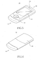
- FIGs. 5 to 8 show appearances of the terminal 100 before and after the keypad 111 is opened.
- the camera housing 129 is accommodated in the camera receiving portion 119 and is thus closed by the battery cover 103.
- the user can activate multimedia functions of the terminal 100 through the button member 111b in the side surface of the terminal or the functional keypad 123 in the second housing 102.
- the elastic member 203 When the keypad 111 is being closed, the elastic member 203 provides the elastic force to move the second housing 102 toward the lower side of the first housing 101 while being in the state that both ends thereof are far from each other. At the same time, the guide ribs 213 are each blocked by each of the stopper ribs 223 of the rear case 102b, thereby preventing the second housing 102 from moving downward any more beyond the first housing 101. Therefore, the second housing 102 can be maintained in the stable stationary state while closing the keypad 111.
- the camera housing 129 has escaped from the camera receiving portion 119 and is thus in the state capable of photographing. Then, the user can photograph either images or moving pictures of subjects using the terminal 100, and can perform voice calls calling a counterpart and edit and send short text messages using the keypad 111 opened.
- the elastic member 203 When the keypad 111 is being opened, the elastic member 203 provides the elastic force to move the second housing 102 toward the upper side of the first housing 101 while being in the state that both ends thereof are far from each other. At the same time, the guide ribs 213 are blocked by the front case 102a, thereby restraining the second housing 102 from moving upward any more beyond the first housing 101. Therefore, the second housing 102 can be maintained in the stable stationary state while opening the keypad 111.
- a sliding type portable terminal can be reduced in thickness because the guide member mounted to the first housing is slidably connected to the rear case of the second housing while surrounding the rear case of the second housing. Further, the first housing is penetrated to form the space for mounting the battery pack and mounts the guide member on one face of the penetrated portion, by which the reduction of thickness of the sliding type portable terminal is more efficiently achieved.
- the sliding type portable terminal employs an elastic member which provides a driving force to slide the second housing. Therefore, it is convenient to use the terminal because the second housing is moved only a part of the entire sliding distance by the user and the rest of the sliding distance by the elastic force of the elastic member.
- the camera module can be mounted on the camera housing formed in the second housing, by which the terminal can be provided with the camera function. Also, the camera receiving portion is formed in the first housing and then it is closed by the battery cover, thereby protecting the camera module mounted to the second housing.
- the terminal can be easily carried with the user because the first and second housing are restrained from freely moving while the first housing is being closed and can be stably manipulated by the user in order to input information for the voice call/short text message while the first housing is being opened.
Landscapes
- Engineering & Computer Science (AREA)
- Signal Processing (AREA)
- Computer Networks & Wireless Communication (AREA)
- Telephone Set Structure (AREA)
Applications Claiming Priority (1)
| Application Number | Priority Date | Filing Date | Title |
|---|---|---|---|
| KR1020060127967A KR100810267B1 (ko) | 2006-12-14 | 2006-12-14 | 슬라이딩형 휴대용 단말기 |
Publications (2)
| Publication Number | Publication Date |
|---|---|
| EP1933537A1 true EP1933537A1 (de) | 2008-06-18 |
| EP1933537B1 EP1933537B1 (de) | 2011-10-19 |
Family
ID=39185802
Family Applications (1)
| Application Number | Title | Priority Date | Filing Date |
|---|---|---|---|
| EP07021336A Ceased EP1933537B1 (de) | 2006-12-14 | 2007-10-31 | Tragbares Endgerät mit Schiebemechanismus |
Country Status (3)
| Country | Link |
|---|---|
| US (1) | US8131330B2 (de) |
| EP (1) | EP1933537B1 (de) |
| KR (1) | KR100810267B1 (de) |
Cited By (2)
| Publication number | Priority date | Publication date | Assignee | Title |
|---|---|---|---|---|
| EP2360898A1 (de) * | 2010-02-15 | 2011-08-24 | Research In Motion Limited | Tragbare elektronische Vorrichtung mit Batterieabdeckung und Sperrmechanismus dafür |
| EP2425146A4 (de) * | 2009-04-30 | 2012-09-19 | Byd Co Ltd | Feder und federnanordnung |
Families Citing this family (6)
| Publication number | Priority date | Publication date | Assignee | Title |
|---|---|---|---|---|
| CN101572296B (zh) * | 2008-04-28 | 2011-12-07 | 深圳富泰宏精密工业有限公司 | 电池盖组件 |
| KR101622220B1 (ko) * | 2009-11-23 | 2016-05-18 | 엘지전자 주식회사 | 휴대용 단말기 |
| CN201797673U (zh) * | 2010-08-24 | 2011-04-13 | 新日兴股份有限公司 | 滑盖式枢纽器及滑盖式可携装置 |
| WO2012108662A2 (en) * | 2011-02-08 | 2012-08-16 | Samsung Electronics Co., Ltd. | Slim-type portable device |
| EP3188458B1 (de) * | 2015-12-29 | 2018-09-12 | Lg Electronics Inc. | Mobiles endgerät |
| CN207926664U (zh) * | 2018-02-09 | 2018-09-28 | 广东欧珀移动通信有限公司 | 移动终端 |
Citations (5)
| Publication number | Priority date | Publication date | Assignee | Title |
|---|---|---|---|---|
| EP1648145A1 (de) | 2004-10-18 | 2006-04-19 | Samsung Electronics Co., Ltd. | Verschiebemodul eines verschiebbaren tragbaren Endgerätes |
| US20060088310A1 (en) * | 2004-10-27 | 2006-04-27 | Lg Electronics Inc. | Camera rotating apparatus of portable terminal |
| US20060098119A1 (en) * | 2004-11-05 | 2006-05-11 | Lg Electronics Inc. | Mobile terminal |
| US20060114646A1 (en) * | 2004-10-13 | 2006-06-01 | Casio Hitachi Mobile Communications Co., Ltd. | Personal digital assistant with slide mechanism |
| US20060231620A1 (en) * | 2005-04-18 | 2006-10-19 | Samsung Electronics Co., Ltd. | Slide module for slide type portable terminal and cover apparatus for external type card mounted thereto |
Family Cites Families (4)
| Publication number | Priority date | Publication date | Assignee | Title |
|---|---|---|---|---|
| KR200365112Y1 (ko) * | 1999-02-25 | 2004-10-21 | 주식회사 팬택앤큐리텔 | 슬라이딩 타입의 플립 개폐장치 |
| KR20050056705A (ko) * | 2003-12-10 | 2005-06-16 | 주식회사 팬택앤큐리텔 | 슬라이드형 이동통신 단말기 |
| KR100537699B1 (ko) | 2005-08-18 | 2005-12-20 | (주)쉘-라인 | 개인휴대단말기 |
| US7778663B2 (en) * | 2006-04-24 | 2010-08-17 | Virgin Mobile Usa, L.P. | Hinge module for three-step open type portable terminal and portable terminal having the same |
-
2006
- 2006-12-14 KR KR1020060127967A patent/KR100810267B1/ko not_active Expired - Fee Related
-
2007
- 2007-10-16 US US11/873,066 patent/US8131330B2/en not_active Expired - Fee Related
- 2007-10-31 EP EP07021336A patent/EP1933537B1/de not_active Ceased
Patent Citations (5)
| Publication number | Priority date | Publication date | Assignee | Title |
|---|---|---|---|---|
| US20060114646A1 (en) * | 2004-10-13 | 2006-06-01 | Casio Hitachi Mobile Communications Co., Ltd. | Personal digital assistant with slide mechanism |
| EP1648145A1 (de) | 2004-10-18 | 2006-04-19 | Samsung Electronics Co., Ltd. | Verschiebemodul eines verschiebbaren tragbaren Endgerätes |
| US20060088310A1 (en) * | 2004-10-27 | 2006-04-27 | Lg Electronics Inc. | Camera rotating apparatus of portable terminal |
| US20060098119A1 (en) * | 2004-11-05 | 2006-05-11 | Lg Electronics Inc. | Mobile terminal |
| US20060231620A1 (en) * | 2005-04-18 | 2006-10-19 | Samsung Electronics Co., Ltd. | Slide module for slide type portable terminal and cover apparatus for external type card mounted thereto |
Cited By (3)
| Publication number | Priority date | Publication date | Assignee | Title |
|---|---|---|---|---|
| EP2425146A4 (de) * | 2009-04-30 | 2012-09-19 | Byd Co Ltd | Feder und federnanordnung |
| EP2360898A1 (de) * | 2010-02-15 | 2011-08-24 | Research In Motion Limited | Tragbare elektronische Vorrichtung mit Batterieabdeckung und Sperrmechanismus dafür |
| US8833805B2 (en) | 2010-02-15 | 2014-09-16 | Blackberry Limited | Portable electronic device with battery cover and locking mechanism therefor |
Also Published As
| Publication number | Publication date |
|---|---|
| US20080146169A1 (en) | 2008-06-19 |
| KR100810267B1 (ko) | 2008-03-06 |
| EP1933537B1 (de) | 2011-10-19 |
| US8131330B2 (en) | 2012-03-06 |
Similar Documents
| Publication | Publication Date | Title |
|---|---|---|
| EP1933537B1 (de) | Tragbares Endgerät mit Schiebemechanismus | |
| CN100512334C (zh) | 滑动式便携式无线终端 | |
| US7184806B2 (en) | Sliding module for mobile terminal | |
| EP1988691B1 (de) | Tragbares Endgerät mit Schiebemechanismus | |
| US7953464B2 (en) | Sliding-type portable terminal | |
| US8634884B2 (en) | Sliding-type portable terminal | |
| EP2009879A1 (de) | Elektronische Vorrichtung | |
| US7157648B2 (en) | Sliding module for portable terminal | |
| CN101073207A (zh) | 便携式终端的相机旋转设备 | |
| KR100827082B1 (ko) | 휴대용 단말기 | |
| US8046034B2 (en) | Sliding-type portable terminal | |
| EP1484921B1 (de) | Kameralinsenbaugruppe für ein tragbares Endgerät | |
| US8478367B2 (en) | Portable terminal having sliding module | |
| US20070161271A1 (en) | Portable terminal having sliding module | |
| EP1909469A2 (de) | Batterieabdeckungsvorrichtung für ein tragbares Endgerät | |
| EP1734725A2 (de) | Tragbares Endgerät mit Verschiebemodul | |
| KR100860678B1 (ko) | 슬라이딩형 휴대용 단말기 | |
| US7499266B2 (en) | Sliding-type portable terminal | |
| KR20080078187A (ko) | 슬라이딩형 휴대용 단말기 | |
| KR20100056862A (ko) | 슬라이딩형 휴대용 단말기 | |
| KR200376765Y1 (ko) | 휴대용 단말기의 슬라이딩 모듈 | |
| KR20060020869A (ko) | 휴대용 단말기의 슬라이딩 모듈 | |
| US20060138999A1 (en) | Battery pack locking device of a portable terminal |
Legal Events
| Date | Code | Title | Description |
|---|---|---|---|
| PUAI | Public reference made under article 153(3) epc to a published international application that has entered the european phase |
Free format text: ORIGINAL CODE: 0009012 |
|
| 17P | Request for examination filed |
Effective date: 20071031 |
|
| AK | Designated contracting states |
Kind code of ref document: A1 Designated state(s): AT BE BG CH CY CZ DE DK EE ES FI FR GB GR HU IE IS IT LI LT LU LV MC MT NL PL PT RO SE SI SK TR |
|
| AX | Request for extension of the european patent |
Extension state: AL BA HR MK RS |
|
| 17Q | First examination report despatched |
Effective date: 20090122 |
|
| AKX | Designation fees paid |
Designated state(s): DE GB NL |
|
| GRAP | Despatch of communication of intention to grant a patent |
Free format text: ORIGINAL CODE: EPIDOSNIGR1 |
|
| GRAS | Grant fee paid |
Free format text: ORIGINAL CODE: EPIDOSNIGR3 |
|
| GRAA | (expected) grant |
Free format text: ORIGINAL CODE: 0009210 |
|
| AK | Designated contracting states |
Kind code of ref document: B1 Designated state(s): DE GB NL |
|
| REG | Reference to a national code |
Ref country code: GB Ref legal event code: FG4D |
|
| REG | Reference to a national code |
Ref country code: NL Ref legal event code: T3 |
|
| REG | Reference to a national code |
Ref country code: DE Ref legal event code: R096 Ref document number: 602007017942 Country of ref document: DE Effective date: 20120126 |
|
| REG | Reference to a national code |
Ref country code: DE Ref legal event code: R082 Ref document number: 602007017942 Country of ref document: DE Representative=s name: GRUENECKER, KINKELDEY, STOCKMAIR & SCHWANHAEUS, DE Ref country code: DE Ref legal event code: R082 Ref document number: 602007017942 Country of ref document: DE Representative=s name: GRUENECKER, DE Ref country code: DE Ref legal event code: R082 Ref document number: 602007017942 Country of ref document: DE Representative=s name: GRUENECKER PATENT- UND RECHTSANWAELTE PARTG MB, DE |
|
| PLBE | No opposition filed within time limit |
Free format text: ORIGINAL CODE: 0009261 |
|
| STAA | Information on the status of an ep patent application or granted ep patent |
Free format text: STATUS: NO OPPOSITION FILED WITHIN TIME LIMIT |
|
| RAP2 | Party data changed (patent owner data changed or rights of a patent transferred) |
Owner name: SAMSUNG ELECTRONICS CO., LTD. |
|
| 26N | No opposition filed |
Effective date: 20120720 |
|
| REG | Reference to a national code |
Ref country code: DE Ref legal event code: R097 Ref document number: 602007017942 Country of ref document: DE Effective date: 20120720 |
|
| PGFP | Annual fee paid to national office [announced via postgrant information from national office to epo] |
Ref country code: NL Payment date: 20210917 Year of fee payment: 15 |
|
| PGFP | Annual fee paid to national office [announced via postgrant information from national office to epo] |
Ref country code: GB Payment date: 20210927 Year of fee payment: 15 |
|
| PGFP | Annual fee paid to national office [announced via postgrant information from national office to epo] |
Ref country code: DE Payment date: 20210916 Year of fee payment: 15 |
|
| REG | Reference to a national code |
Ref country code: DE Ref legal event code: R119 Ref document number: 602007017942 Country of ref document: DE |
|
| REG | Reference to a national code |
Ref country code: NL Ref legal event code: MM Effective date: 20221101 |
|
| GBPC | Gb: european patent ceased through non-payment of renewal fee |
Effective date: 20221031 |
|
| PG25 | Lapsed in a contracting state [announced via postgrant information from national office to epo] |
Ref country code: NL Free format text: LAPSE BECAUSE OF NON-PAYMENT OF DUE FEES Effective date: 20221101 Ref country code: DE Free format text: LAPSE BECAUSE OF NON-PAYMENT OF DUE FEES Effective date: 20230503 |
|
| PG25 | Lapsed in a contracting state [announced via postgrant information from national office to epo] |
Ref country code: GB Free format text: LAPSE BECAUSE OF NON-PAYMENT OF DUE FEES Effective date: 20221031 |