EP1939054A2 - Dispositif d'essuie-glace, en particulier dans un véhicule automobile - Google Patents
Dispositif d'essuie-glace, en particulier dans un véhicule automobile Download PDFInfo
- Publication number
- EP1939054A2 EP1939054A2 EP07119562A EP07119562A EP1939054A2 EP 1939054 A2 EP1939054 A2 EP 1939054A2 EP 07119562 A EP07119562 A EP 07119562A EP 07119562 A EP07119562 A EP 07119562A EP 1939054 A2 EP1939054 A2 EP 1939054A2
- Authority
- EP
- European Patent Office
- Prior art keywords
- wiper
- wiper device
- shaft
- windscreen wiper
- pivot axis
- Prior art date
- Legal status (The legal status is an assumption and is not a legal conclusion. Google has not performed a legal analysis and makes no representation as to the accuracy of the status listed.)
- Granted
Links
- 230000033001 locomotion Effects 0.000 claims abstract description 48
- 230000005540 biological transmission Effects 0.000 claims description 19
- 230000001427 coherent effect Effects 0.000 claims description 3
- 238000004140 cleaning Methods 0.000 description 2
- 230000006978 adaptation Effects 0.000 description 1
- 230000008878 coupling Effects 0.000 description 1
- 238000010168 coupling process Methods 0.000 description 1
- 238000005859 coupling reaction Methods 0.000 description 1
- 230000001419 dependent effect Effects 0.000 description 1
- 238000011161 development Methods 0.000 description 1
- 230000018109 developmental process Effects 0.000 description 1
- 238000009434 installation Methods 0.000 description 1
- 230000000284 resting effect Effects 0.000 description 1
- 238000010079 rubber tapping Methods 0.000 description 1
- 208000029257 vision disease Diseases 0.000 description 1
- 230000004393 visual impairment Effects 0.000 description 1
Images


Classifications
-
- B—PERFORMING OPERATIONS; TRANSPORTING
- B60—VEHICLES IN GENERAL
- B60S—SERVICING, CLEANING, REPAIRING, SUPPORTING, LIFTING, OR MANOEUVRING OF VEHICLES, NOT OTHERWISE PROVIDED FOR
- B60S1/00—Cleaning of vehicles
- B60S1/02—Cleaning windscreens, windows or optical devices
- B60S1/04—Wipers or the like, e.g. scrapers
- B60S1/32—Wipers or the like, e.g. scrapers characterised by constructional features of wiper blade arms or blades
- B60S1/34—Wiper arms; Mountings therefor
- B60S1/3486—Means to allow blade to follow curvature of the screen (i.e. rotation along longitudinal axis of the arm)
-
- B—PERFORMING OPERATIONS; TRANSPORTING
- B60—VEHICLES IN GENERAL
- B60S—SERVICING, CLEANING, REPAIRING, SUPPORTING, LIFTING, OR MANOEUVRING OF VEHICLES, NOT OTHERWISE PROVIDED FOR
- B60S1/00—Cleaning of vehicles
- B60S1/02—Cleaning windscreens, windows or optical devices
- B60S1/04—Wipers or the like, e.g. scrapers
- B60S1/043—Attachment of the wiper assembly to the vehicle
- B60S1/0433—Attachement of a wiper modular assembly to the vehicle
-
- B—PERFORMING OPERATIONS; TRANSPORTING
- B60—VEHICLES IN GENERAL
- B60S—SERVICING, CLEANING, REPAIRING, SUPPORTING, LIFTING, OR MANOEUVRING OF VEHICLES, NOT OTHERWISE PROVIDED FOR
- B60S1/00—Cleaning of vehicles
- B60S1/02—Cleaning windscreens, windows or optical devices
- B60S1/04—Wipers or the like, e.g. scrapers
- B60S1/06—Wipers or the like, e.g. scrapers characterised by the drive
- B60S1/16—Means for transmitting drive
- B60S1/18—Means for transmitting drive mechanically
- B60S1/24—Means for transmitting drive mechanically by rotary cranks
Definitions
- the invention relates to a windshield wiper device, in particular in a motor vehicle, according to the preamble of claim 1.
- a windshield wiper device for a motor vehicle is known, the wiper arm is mounted on a rotatably mounted wiper shaft, which is reversibly driven by an electric drive motor.
- the armature of the drive motor is coupled via a transmission with an output shaft, which is connected via a wiper linkage with the wiper shaft.
- the motion transmission thus takes place from the armature of the electric drive motor via the transmission, the output shaft and the wiper linkage to the wiper shaft.
- the curvature of the disk to be cleaned is to be considered in windscreen wiper devices.
- the disc curvature in the A-pillars adjacent areas is relatively large, which can lead to a poorer wiping result, since the wiper blade no longer rests flat on the disc and the contact pressure over the length of the wiper blade is no longer evenly distributed.
- efforts are being made to have the largest possible field of view effectively cleaned by the windshield wiper device, which may also include areas of stronger disc curvatures.
- the invention has for its object to provide a windshield wiper device, which is characterized by a good cleaning result.
- a windshield wiper device which is characterized by a good cleaning result.
- the windshield wiper device which is used in particular in a motor vehicle, has an electric drive motor which is coupled in terms of movement by means of a transmission device with a wiper shaft to which a wiper arm is fastened.
- the wiper shaft is rotatably mounted about a rotation axis, this rotation movement covering the wiping field of the wiper arm.
- the wiper shaft is pivotably mounted about a pivot axis, wherein pivot axis and rotation axis of the wiper shaft are at an angle to each other.
- the wiper shaft is acted upon by an actuator about the pivot axis.
- the wiper shaft in addition to the rotational movement on a further movement possibility, namely the pivoting movement about the pivot axis, which is at an angle to the axis of rotation.
- This additional degree of freedom of the wiper shaft and the wiper arm is bound via an actuator which acts on the wiper shaft or the wiper arm.
- the actuator performs an actuating movement, which leads to a pivoting of the wiper shaft about the pivot axis.
- the pivoting movement is exerted in particular simultaneously with the rotational movement of the wiper shaft and the wiper arm, so that the wiper shaft and wiper arm perform a three-dimensional rotational and pivotal movement as a whole.
- the pivot axis is advantageously at least approximately perpendicular to the axis of rotation of the wiper shaft, wherein in principle also deviating angle values come into consideration.
- both a cutting of the axes and a crossing with a distance of the axes to each other is possible.
- the drive motor, the transmission device and the wiper shaft including wiper arm form a coherent module that is pivotably mounted about the pivot axis.
- the pivoting movement relative to the vehicle body which is exercised jointly in a modular design of drive motor, transmission device and wiper shaft or wiper arm of these components.
- the embodiment with the support frame has the advantage that the support frame in the vehicle can be anchored to the vehicle body and that the pivoting movement relative to the support frame takes place, which means in particular a considerable structural and installation simplification.
- the pivoting movement is kinematically coupled to the rotational movement of the wiper shaft.
- the drive motor at the same time forms the actuator, which is responsible for generating the pivoting movement of the wiper shaft about the pivot axis.
- This kinematical coupling of pivoting movement and rotational movement via the drive motor for example, a rotating component of the windscreen wiper device, which is primarily responsible for generating the rotational movement of the wiper arm, provided with a cam curve which cooperates with a sensing or control element, wherein the actuating element as the wiper shaft Function of the cam curve pivoted.
- the adjusting movement acting on the wiper shaft is derived from the rotating movement of the component, which leads to the pivoting movement of the wiper shaft.
- the design of the cam curve allows this with simple structural means an adaptation to different disc curvatures.
- a rotating component of the windshield wiper device in particular a component of the transmission device between the drive motor and wiper shaft is used, for example a crank which has a surface configuration forming the cam curve.
- the cam curve is tapped or scanned by the adjusting element, wherein the adjusting element is designed, for example, as a roller tappet, which slides over the cam curve or under which the cam curve is moved along.
- the wiper shaft or another component of the windscreen wiper device which carries out the pivoting movement, is subjected to a defined pivoting position by a spring element. This spring element presses cam cam and scanning element to each other, so that the cam surface is in permanent contact with the scanning or control element.
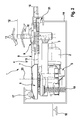
- the windshield wiper device 1 comprises an electric drive motor 2, for example a permanent-magnet DC motor, whose armature has the axis of rotation 3 and is rotationally coupled via a transmission device 4 to a wiper shaft 10 to which a wiper arm 12 is attached.
- an electric drive motor 2 for example a permanent-magnet DC motor, whose armature has the axis of rotation 3 and is rotationally coupled via a transmission device 4 to a wiper shaft 10 to which a wiper arm 12 is attached.
- a reversing drive movement of the drive motor 2 a reversing rotational movement of the wiper shaft 10 is thus generated around the wiper shaft rotation axis 11, whereupon the wiper arm 12 slides over the disc 13 to be cleaned.
- the transmission device 4 comprises a gear 5, via which the rotational movement of the armature of the drive motor 2 is transmitted to an output shaft on which a crank 6 is rotatably mounted, which is integral with a part-circular cam, wherein on the upper side of the cam plate a cam curve. 7 is arranged along a pitch circle.
- a transmission link 8 is rotatably coupled to the cam, which is rotatably connected on its side facing away from the crank 6 via a further rotary joint with a cranked link 9, which is rotatably connected to the wiper shaft 10.
- the rotational movement of the crank 6 is transmitted via the links 8 and 9 in the rotational movement of the wiper shaft 10 and the wiper arm 12 about the rotation axis 11.
- the windshield wiper device is associated with a supporting or auxiliary frame 14, in which all components of the windscreen wiper device are pivotally received.
- the support frame 14 is connected via various attachment points 16 fixed to the vehicle body.
- the transmission device 4 and the wiper shaft 10 including wiper arm 12 are pivotally received; the pivot axis is identified by reference numeral 15.
- all the components of the windshield wiper device pivotably mounted about the swivel axis 15 form a coherent module that is to be pivoted overall about the pivot axis 15.
- about such a pivoting movement of the curvature of the disc 13 can be taken into account, so that the wiper arm 12 rests flat on the disc even when reaching the more curved side portions of the disc 13.
- roller tappet 17 Upon rotation of the crank 6 thus the roller tappet 17 is permanently on the cam contour of the cam curve 7, wherein the elevations and depressions in the cam curve 7 due to the support on the roller tappet 17 on the one hand and the Federkraftbeaufschlagung by the spring element 18 on the other hand to a pivotal movement about the pivot axis 15 lead.
- Fig. 2 the module consisting of drive motor 2, transmission device 4 and wiper shaft 10 including wiper arm 12, pivotally mounted in the support frame 14 on one side in a bearing 21, the second, opposite bearing 22 is made Fig. 3 seen.
- the pivot axis 15 is perpendicular to the axis of rotation 11 and is slightly below and parallel to the transfer link 8.
- the wiper shaft 10 from the image plane of Fig. 2 pivoted out or into this.
- Fig. 2 projected the axis of rotation 11 of the wiper shaft 10 in the image plane, such that three axes of rotation 11 are exemplified, each associated with a specific pivot position.
- the part-circular Design of the cam curve 7 off Fig. 1 But basically enough, since the drive motor exerts a reversing drive movement and accordingly the angular extent of the cam curve can be adapted to the reversion movement of the armature of the drive motor.
Landscapes
- Engineering & Computer Science (AREA)
- Mechanical Engineering (AREA)
- Transmission Devices (AREA)
- Connection Of Motors, Electrical Generators, Mechanical Devices, And The Like (AREA)
Applications Claiming Priority (1)
| Application Number | Priority Date | Filing Date | Title |
|---|---|---|---|
| DE200610062003 DE102006062003A1 (de) | 2006-12-29 | 2006-12-29 | Scheibenwischvorrichtung, insbesondere in einem Kraftfahrzeug |
Publications (3)
| Publication Number | Publication Date |
|---|---|
| EP1939054A2 true EP1939054A2 (fr) | 2008-07-02 |
| EP1939054A3 EP1939054A3 (fr) | 2009-12-09 |
| EP1939054B1 EP1939054B1 (fr) | 2012-02-15 |
Family
ID=39203325
Family Applications (1)
| Application Number | Title | Priority Date | Filing Date |
|---|---|---|---|
| EP20070119562 Not-in-force EP1939054B1 (fr) | 2006-12-29 | 2007-10-30 | Dispositif d'essuie-glace, en particulier dans un véhicule automobile |
Country Status (3)
| Country | Link |
|---|---|
| EP (1) | EP1939054B1 (fr) |
| DE (1) | DE102006062003A1 (fr) |
| ES (1) | ES2378328T3 (fr) |
Cited By (4)
| Publication number | Priority date | Publication date | Assignee | Title |
|---|---|---|---|---|
| FR2961150A1 (fr) * | 2010-06-10 | 2011-12-16 | Peugeot Citroen Automobiles Sa | Mecanisme d'essuie-vitre comprenant des moyens de reglage de l'angle d'attaque d'une raclette de bras-balai d'essuie-vitre |
| US20180229693A1 (en) * | 2017-02-16 | 2018-08-16 | Valeo Systèmes d'Essuyage | Drive device for driving the rotation of a wiper arm, particularly for a panoramic windscreen |
| DE112018001831T5 (de) | 2017-04-28 | 2019-12-12 | Scania Cv Ab | Scheibenwischervorrichtung für ein Kraftfahrzeug und Verfahren zum Wischen einer Windschutzscheibe |
| EP3472005A4 (fr) * | 2016-06-15 | 2020-01-22 | Scania CV AB | Dispositif d'essuie-glace |
Citations (2)
| Publication number | Priority date | Publication date | Assignee | Title |
|---|---|---|---|---|
| DE19801296A1 (de) | 1998-01-16 | 1999-07-22 | Bosch Gmbh Robert | Wischerlager |
| FR2907733A1 (fr) | 2006-10-30 | 2008-05-02 | Valeo Systemes Dessuyage | Systeme d'essuyage pour pare-brise de vehicule automobile |
Family Cites Families (1)
| Publication number | Priority date | Publication date | Assignee | Title |
|---|---|---|---|---|
| DE102004005067A1 (de) | 2004-02-02 | 2005-08-18 | Robert Bosch Gmbh | Scheibenwischvorrichtung, insbesondere für ein Kraftfahrzeug |
-
2006
- 2006-12-29 DE DE200610062003 patent/DE102006062003A1/de not_active Withdrawn
-
2007
- 2007-10-30 ES ES07119562T patent/ES2378328T3/es active Active
- 2007-10-30 EP EP20070119562 patent/EP1939054B1/fr not_active Not-in-force
Patent Citations (2)
| Publication number | Priority date | Publication date | Assignee | Title |
|---|---|---|---|---|
| DE19801296A1 (de) | 1998-01-16 | 1999-07-22 | Bosch Gmbh Robert | Wischerlager |
| FR2907733A1 (fr) | 2006-10-30 | 2008-05-02 | Valeo Systemes Dessuyage | Systeme d'essuyage pour pare-brise de vehicule automobile |
Cited By (9)
| Publication number | Priority date | Publication date | Assignee | Title |
|---|---|---|---|---|
| FR2961150A1 (fr) * | 2010-06-10 | 2011-12-16 | Peugeot Citroen Automobiles Sa | Mecanisme d'essuie-vitre comprenant des moyens de reglage de l'angle d'attaque d'une raclette de bras-balai d'essuie-vitre |
| EP3472005A4 (fr) * | 2016-06-15 | 2020-01-22 | Scania CV AB | Dispositif d'essuie-glace |
| US20180229693A1 (en) * | 2017-02-16 | 2018-08-16 | Valeo Systèmes d'Essuyage | Drive device for driving the rotation of a wiper arm, particularly for a panoramic windscreen |
| FR3062830A1 (fr) * | 2017-02-16 | 2018-08-17 | Valeo Systemes D'essuyage | Dispositif d'entrainement en rotation d'un bras d'essuie-glace, notamment pour un pare-brise panoramique |
| EP3363695A1 (fr) * | 2017-02-16 | 2018-08-22 | Valeo Systèmes d'Essuyage | Dispositif d entraînement en rotation d'un bras d essuie-glace, notamment pour un pare-brise panoramique |
| CN108437935A (zh) * | 2017-02-16 | 2018-08-24 | 法雷奥系统公司 | 用于驱动特别是全景风挡的擦拭器臂旋转的驱动装置 |
| CN108437935B (zh) * | 2017-02-16 | 2021-07-13 | 法雷奥系统公司 | 用于驱动特别是全景风挡的擦拭器臂旋转的驱动装置 |
| DE112018001831T5 (de) | 2017-04-28 | 2019-12-12 | Scania Cv Ab | Scheibenwischervorrichtung für ein Kraftfahrzeug und Verfahren zum Wischen einer Windschutzscheibe |
| DE112018001831B4 (de) | 2017-04-28 | 2024-05-29 | Scania Cv Ab | Scheibenwischervorrichtung für ein Kraftfahrzeug und Verfahren zum Wischen einer Windschutzscheibe |
Also Published As
| Publication number | Publication date |
|---|---|
| ES2378328T3 (es) | 2012-04-11 |
| EP1939054B1 (fr) | 2012-02-15 |
| DE102006062003A1 (de) | 2008-07-03 |
| EP1939054A3 (fr) | 2009-12-09 |
Similar Documents
| Publication | Publication Date | Title |
|---|---|---|
| EP2094541B1 (fr) | Dispositif d'entraînement électromagnétique destiné à être utilisé dans le hayon arrière d'un véhicule automobile | |
| EP1453708B1 (fr) | Dispositif d'essuie-glace notamment destine a un vehicule | |
| EP0541564B1 (fr) | Essuie-glace de vehicules a moteur | |
| EP1939054B1 (fr) | Dispositif d'essuie-glace, en particulier dans un véhicule automobile | |
| DE4032762C1 (fr) | ||
| DE19744906A1 (de) | Wischvorrichtung mit Wischwinkelbegrenzung | |
| EP0094521B1 (fr) | Dispositif pour essuyer des glaces d'automobiles | |
| EP0779191A1 (fr) | Dispositif d'essuie-glace pour des véhicules automobiles | |
| DE10338662B4 (de) | Scheibenwischeranlage für ein Kraftfahrzeug | |
| WO2005095170A1 (fr) | Ensemble bras d'essuie-glace | |
| EP1908654A1 (fr) | Dispositif d'essuie-glaces | |
| DE102005045928B4 (de) | Wischervorrichtung, die mittels eines plattenförmigen Hebels oder eines einen gebogenen Abschnitt aufweisenden Hebels angebracht ist | |
| EP1748916B1 (fr) | Dispositif d'entrainement pour un bras d'essuie-glace d'un systeme essuie-glace | |
| EP1908655B1 (fr) | Dispositif d'essuyage pour une vitre panoramique | |
| EP1117573B1 (fr) | Commande d'essuie-glace | |
| DE102015209035A1 (de) | Wischerantriebsvorrichtung | |
| DE10355894B4 (de) | Scheibenwischvorrichtung für Fahrzeuge | |
| WO2002018187A1 (fr) | Mecanisme d'entrainement d'un systeme d'essuie-glace contenant un ressort a torsion | |
| DE102007061377A1 (de) | Scheibenwischerarm | |
| WO2005063533A1 (fr) | Systeme d'essuie-glace pour essuyer un pare-brise | |
| EP0939711A1 (fr) | Systeme d'essuie-glace, notamment pour vitres de vehicules a moteur | |
| DE102012206957A1 (de) | Wischarmvorrichtung | |
| DE102006009488A1 (de) | Wischarm | |
| DE10132112A1 (de) | Wischvorrichtung mit einem Abklappmechanismus | |
| DE10132171A1 (de) | Wischvorrichtung, insbesondere für Kraftfahrzeugscheiben mit einem Modulträger |
Legal Events
| Date | Code | Title | Description |
|---|---|---|---|
| PUAI | Public reference made under article 153(3) epc to a published international application that has entered the european phase |
Free format text: ORIGINAL CODE: 0009012 |
|
| AK | Designated contracting states |
Kind code of ref document: A2 Designated state(s): AT BE BG CH CY CZ DE DK EE ES FI FR GB GR HU IE IS IT LI LT LU LV MC MT NL PL PT RO SE SI SK TR |
|
| AX | Request for extension of the european patent |
Extension state: AL BA HR MK RS |
|
| PUAL | Search report despatched |
Free format text: ORIGINAL CODE: 0009013 |
|
| AK | Designated contracting states |
Kind code of ref document: A3 Designated state(s): AT BE BG CH CY CZ DE DK EE ES FI FR GB GR HU IE IS IT LI LT LU LV MC MT NL PL PT RO SE SI SK TR |
|
| AX | Request for extension of the european patent |
Extension state: AL BA HR MK RS |
|
| 17P | Request for examination filed |
Effective date: 20100609 |
|
| 17Q | First examination report despatched |
Effective date: 20100712 |
|
| AKX | Designation fees paid |
Designated state(s): CZ DE ES FR |
|
| GRAP | Despatch of communication of intention to grant a patent |
Free format text: ORIGINAL CODE: EPIDOSNIGR1 |
|
| GRAS | Grant fee paid |
Free format text: ORIGINAL CODE: EPIDOSNIGR3 |
|
| GRAA | (expected) grant |
Free format text: ORIGINAL CODE: 0009210 |
|
| AK | Designated contracting states |
Kind code of ref document: B1 Designated state(s): CZ DE ES FR |
|
| REG | Reference to a national code |
Ref country code: ES Ref legal event code: FG2A Ref document number: 2378328 Country of ref document: ES Kind code of ref document: T3 Effective date: 20120411 |
|
| REG | Reference to a national code |
Ref country code: DE Ref legal event code: R096 Ref document number: 502007009274 Country of ref document: DE Effective date: 20120412 |
|
| PLBE | No opposition filed within time limit |
Free format text: ORIGINAL CODE: 0009261 |
|
| STAA | Information on the status of an ep patent application or granted ep patent |
Free format text: STATUS: NO OPPOSITION FILED WITHIN TIME LIMIT |
|
| 26N | No opposition filed |
Effective date: 20121116 |
|
| REG | Reference to a national code |
Ref country code: DE Ref legal event code: R097 Ref document number: 502007009274 Country of ref document: DE Effective date: 20121116 |
|
| REG | Reference to a national code |
Ref country code: FR Ref legal event code: PLFP Year of fee payment: 9 |
|
| REG | Reference to a national code |
Ref country code: FR Ref legal event code: PLFP Year of fee payment: 10 |
|
| REG | Reference to a national code |
Ref country code: FR Ref legal event code: PLFP Year of fee payment: 11 |
|
| PGFP | Annual fee paid to national office [announced via postgrant information from national office to epo] |
Ref country code: DE Payment date: 20171206 Year of fee payment: 11 Ref country code: CZ Payment date: 20171017 Year of fee payment: 11 Ref country code: FR Payment date: 20171023 Year of fee payment: 11 |
|
| PGFP | Annual fee paid to national office [announced via postgrant information from national office to epo] |
Ref country code: ES Payment date: 20171103 Year of fee payment: 11 |
|
| REG | Reference to a national code |
Ref country code: DE Ref legal event code: R119 Ref document number: 502007009274 Country of ref document: DE |
|
| PG25 | Lapsed in a contracting state [announced via postgrant information from national office to epo] |
Ref country code: DE Free format text: LAPSE BECAUSE OF NON-PAYMENT OF DUE FEES Effective date: 20190501 Ref country code: CZ Free format text: LAPSE BECAUSE OF NON-PAYMENT OF DUE FEES Effective date: 20181030 |
|
| PG25 | Lapsed in a contracting state [announced via postgrant information from national office to epo] |
Ref country code: FR Free format text: LAPSE BECAUSE OF NON-PAYMENT OF DUE FEES Effective date: 20181031 |
|
| REG | Reference to a national code |
Ref country code: ES Ref legal event code: FD2A Effective date: 20191204 |
|
| PG25 | Lapsed in a contracting state [announced via postgrant information from national office to epo] |
Ref country code: ES Free format text: LAPSE BECAUSE OF NON-PAYMENT OF DUE FEES Effective date: 20181031 |