EP1942083A1 - Procédé et appareil pour la fabrication dýune préforme pour fibre optique active, fibre optique active et amplificateur - Google Patents
Procédé et appareil pour la fabrication dýune préforme pour fibre optique active, fibre optique active et amplificateur Download PDFInfo
- Publication number
- EP1942083A1 EP1942083A1 EP06125655A EP06125655A EP1942083A1 EP 1942083 A1 EP1942083 A1 EP 1942083A1 EP 06125655 A EP06125655 A EP 06125655A EP 06125655 A EP06125655 A EP 06125655A EP 1942083 A1 EP1942083 A1 EP 1942083A1
- Authority
- EP
- European Patent Office
- Prior art keywords
- silica
- primary
- preform
- tube
- optical fiber
- Prior art date
- Legal status (The legal status is an assumption and is not a legal conclusion. Google has not performed a legal analysis and makes no representation as to the accuracy of the status listed.)
- Withdrawn
Links
- 239000013307 optical fiber Substances 0.000 title claims abstract description 82
- 238000000034 method Methods 0.000 title claims abstract description 52
- VYPSYNLAJGMNEJ-UHFFFAOYSA-N Silicium dioxide Chemical compound O=[Si]=O VYPSYNLAJGMNEJ-UHFFFAOYSA-N 0.000 claims abstract description 450
- 239000000377 silicon dioxide Substances 0.000 claims abstract description 220
- 239000000835 fiber Substances 0.000 claims abstract description 76
- 239000000463 material Substances 0.000 claims abstract description 67
- 230000003287 optical effect Effects 0.000 claims abstract description 49
- 230000003321 amplification Effects 0.000 claims abstract description 16
- 238000003199 nucleic acid amplification method Methods 0.000 claims abstract description 16
- 230000000694 effects Effects 0.000 claims abstract description 10
- 238000005253 cladding Methods 0.000 claims description 28
- 239000002019 doping agent Substances 0.000 claims description 22
- 238000010438 heat treatment Methods 0.000 claims description 17
- 239000004038 photonic crystal Substances 0.000 claims description 14
- 229910052691 Erbium Inorganic materials 0.000 claims description 8
- UYAHIZSMUZPPFV-UHFFFAOYSA-N erbium Chemical compound [Er] UYAHIZSMUZPPFV-UHFFFAOYSA-N 0.000 claims description 7
- 229910052751 metal Inorganic materials 0.000 claims description 6
- 239000002184 metal Substances 0.000 claims description 6
- 230000000737 periodic effect Effects 0.000 claims description 6
- 238000000227 grinding Methods 0.000 claims description 5
- 229910052779 Neodymium Inorganic materials 0.000 claims description 4
- 229910052804 chromium Inorganic materials 0.000 claims description 4
- 150000001875 compounds Chemical class 0.000 claims description 4
- 229910052802 copper Inorganic materials 0.000 claims description 4
- 229910052742 iron Inorganic materials 0.000 claims description 4
- 229910052748 manganese Inorganic materials 0.000 claims description 4
- 150000002739 metals Chemical class 0.000 claims description 4
- QEFYFXOXNSNQGX-UHFFFAOYSA-N neodymium atom Chemical compound [Nd] QEFYFXOXNSNQGX-UHFFFAOYSA-N 0.000 claims description 4
- 229910052759 nickel Inorganic materials 0.000 claims description 4
- 239000000843 powder Substances 0.000 claims description 4
- 229910052719 titanium Inorganic materials 0.000 claims description 4
- 229910052720 vanadium Inorganic materials 0.000 claims description 4
- 229910052692 Dysprosium Inorganic materials 0.000 claims description 3
- 229910052693 Europium Inorganic materials 0.000 claims description 3
- 229910052689 Holmium Inorganic materials 0.000 claims description 3
- 229910052775 Thulium Inorganic materials 0.000 claims description 3
- 229910052769 Ytterbium Inorganic materials 0.000 claims description 3
- KBQHZAAAGSGFKK-UHFFFAOYSA-N dysprosium atom Chemical compound [Dy] KBQHZAAAGSGFKK-UHFFFAOYSA-N 0.000 claims description 3
- OGPBJKLSAFTDLK-UHFFFAOYSA-N europium atom Chemical compound [Eu] OGPBJKLSAFTDLK-UHFFFAOYSA-N 0.000 claims description 3
- 238000011049 filling Methods 0.000 claims description 3
- KJZYNXUDTRRSPN-UHFFFAOYSA-N holmium atom Chemical compound [Ho] KJZYNXUDTRRSPN-UHFFFAOYSA-N 0.000 claims description 3
- 150000003624 transition metals Chemical class 0.000 claims description 3
- NAWDYIZEMPQZHO-UHFFFAOYSA-N ytterbium Chemical compound [Yb] NAWDYIZEMPQZHO-UHFFFAOYSA-N 0.000 claims description 3
- 238000005137 deposition process Methods 0.000 claims description 2
- 229920006240 drawn fiber Polymers 0.000 claims description 2
- 238000002156 mixing Methods 0.000 claims description 2
- 229910052723 transition metal Inorganic materials 0.000 claims description 2
- 238000007781 pre-processing Methods 0.000 claims 1
- 239000011162 core material Substances 0.000 description 40
- 230000002093 peripheral effect Effects 0.000 description 13
- 238000000576 coating method Methods 0.000 description 9
- 239000011248 coating agent Substances 0.000 description 8
- 239000002245 particle Substances 0.000 description 7
- 230000005540 biological transmission Effects 0.000 description 6
- 238000000151 deposition Methods 0.000 description 6
- 239000011521 glass Substances 0.000 description 6
- 150000002500 ions Chemical class 0.000 description 6
- 238000006243 chemical reaction Methods 0.000 description 5
- 238000004891 communication Methods 0.000 description 5
- 230000008021 deposition Effects 0.000 description 5
- 238000012546 transfer Methods 0.000 description 5
- 230000005281 excited state Effects 0.000 description 4
- 238000004519 manufacturing process Methods 0.000 description 4
- 238000002844 melting Methods 0.000 description 4
- 230000008018 melting Effects 0.000 description 4
- 238000005086 pumping Methods 0.000 description 4
- 230000002269 spontaneous effect Effects 0.000 description 4
- 238000009826 distribution Methods 0.000 description 3
- 239000007789 gas Substances 0.000 description 3
- 230000005855 radiation Effects 0.000 description 3
- 229910052761 rare earth metal Inorganic materials 0.000 description 3
- 238000004804 winding Methods 0.000 description 3
- 238000010521 absorption reaction Methods 0.000 description 2
- 230000002238 attenuated effect Effects 0.000 description 2
- 238000005229 chemical vapour deposition Methods 0.000 description 2
- -1 erbium ions Chemical class 0.000 description 2
- 230000005283 ground state Effects 0.000 description 2
- 239000007788 liquid Substances 0.000 description 2
- 239000000203 mixture Substances 0.000 description 2
- 238000005268 plasma chemical vapour deposition Methods 0.000 description 2
- 150000002910 rare earth metals Chemical class 0.000 description 2
- 239000000376 reactant Substances 0.000 description 2
- 238000011160 research Methods 0.000 description 2
- 238000007789 sealing Methods 0.000 description 2
- 239000004065 semiconductor Substances 0.000 description 2
- 238000005245 sintering Methods 0.000 description 2
- 239000007787 solid Substances 0.000 description 2
- OKTJSMMVPCPJKN-UHFFFAOYSA-N Carbon Chemical compound [C] OKTJSMMVPCPJKN-UHFFFAOYSA-N 0.000 description 1
- 229910006113 GeCl4 Inorganic materials 0.000 description 1
- UFHFLCQGNIYNRP-UHFFFAOYSA-N Hydrogen Chemical compound [H][H] UFHFLCQGNIYNRP-UHFFFAOYSA-N 0.000 description 1
- 229910019210 POCl4 Inorganic materials 0.000 description 1
- 229910003910 SiCl4 Inorganic materials 0.000 description 1
- 229910004014 SiF4 Inorganic materials 0.000 description 1
- 235000017899 Spathodea campanulata Nutrition 0.000 description 1
- 239000000443 aerosol Substances 0.000 description 1
- 150000001805 chlorine compounds Chemical class 0.000 description 1
- 238000001816 cooling Methods 0.000 description 1
- 230000008878 coupling Effects 0.000 description 1
- 238000010168 coupling process Methods 0.000 description 1
- 238000005859 coupling reaction Methods 0.000 description 1
- 238000005520 cutting process Methods 0.000 description 1
- 230000001419 dependent effect Effects 0.000 description 1
- 238000007865 diluting Methods 0.000 description 1
- 230000003028 elevating effect Effects 0.000 description 1
- 238000005516 engineering process Methods 0.000 description 1
- 230000007613 environmental effect Effects 0.000 description 1
- 239000005350 fused silica glass Substances 0.000 description 1
- 229910002804 graphite Inorganic materials 0.000 description 1
- 239000010439 graphite Substances 0.000 description 1
- 150000004820 halides Chemical class 0.000 description 1
- 239000001257 hydrogen Substances 0.000 description 1
- 229910052739 hydrogen Inorganic materials 0.000 description 1
- 238000002347 injection Methods 0.000 description 1
- 239000007924 injection Substances 0.000 description 1
- 238000003780 insertion Methods 0.000 description 1
- 230000037431 insertion Effects 0.000 description 1
- 239000007791 liquid phase Substances 0.000 description 1
- 230000004807 localization Effects 0.000 description 1
- 230000003647 oxidation Effects 0.000 description 1
- 238000007254 oxidation reaction Methods 0.000 description 1
- 239000012071 phase Substances 0.000 description 1
- 230000000704 physical effect Effects 0.000 description 1
- 230000010287 polarization Effects 0.000 description 1
- 238000012545 processing Methods 0.000 description 1
- 230000008929 regeneration Effects 0.000 description 1
- 238000011069 regeneration method Methods 0.000 description 1
- 230000008054 signal transmission Effects 0.000 description 1
- FDNAPBUWERUEDA-UHFFFAOYSA-N silicon tetrachloride Chemical compound Cl[Si](Cl)(Cl)Cl FDNAPBUWERUEDA-UHFFFAOYSA-N 0.000 description 1
- ABTOQLMXBSRXSM-UHFFFAOYSA-N silicon tetrafluoride Chemical compound F[Si](F)(F)F ABTOQLMXBSRXSM-UHFFFAOYSA-N 0.000 description 1
- 239000004071 soot Substances 0.000 description 1
- 238000009987 spinning Methods 0.000 description 1
- 238000010561 standard procedure Methods 0.000 description 1
- 230000004936 stimulating effect Effects 0.000 description 1
- 239000000758 substrate Substances 0.000 description 1
- IEXRMSFAVATTJX-UHFFFAOYSA-N tetrachlorogermane Chemical compound Cl[Ge](Cl)(Cl)Cl IEXRMSFAVATTJX-UHFFFAOYSA-N 0.000 description 1
- 230000001052 transient effect Effects 0.000 description 1
- 239000011800 void material Substances 0.000 description 1
Images


Classifications
-
- C—CHEMISTRY; METALLURGY
- C03—GLASS; MINERAL OR SLAG WOOL
- C03B—MANUFACTURE, SHAPING, OR SUPPLEMENTARY PROCESSES
- C03B37/00—Manufacture or treatment of flakes, fibres, or filaments from softened glass, minerals, or slags
- C03B37/01—Manufacture of glass fibres or filaments
- C03B37/012—Manufacture of preforms for drawing fibres or filaments
-
- G—PHYSICS
- G02—OPTICS
- G02B—OPTICAL ELEMENTS, SYSTEMS OR APPARATUS
- G02B6/00—Light guides; Structural details of arrangements comprising light guides and other optical elements, e.g. couplings
- G02B6/02—Optical fibres with cladding with or without a coating
-
- C—CHEMISTRY; METALLURGY
- C03—GLASS; MINERAL OR SLAG WOOL
- C03B—MANUFACTURE, SHAPING, OR SUPPLEMENTARY PROCESSES
- C03B37/00—Manufacture or treatment of flakes, fibres, or filaments from softened glass, minerals, or slags
- C03B37/01—Manufacture of glass fibres or filaments
- C03B37/012—Manufacture of preforms for drawing fibres or filaments
- C03B37/01205—Manufacture of preforms for drawing fibres or filaments starting from tubes, rods, fibres or filaments
- C03B37/01211—Manufacture of preforms for drawing fibres or filaments starting from tubes, rods, fibres or filaments by inserting one or more rods or tubes into a tube
- C03B37/0122—Manufacture of preforms for drawing fibres or filaments starting from tubes, rods, fibres or filaments by inserting one or more rods or tubes into a tube for making preforms of photonic crystal, microstructured or holey optical fibres
-
- C—CHEMISTRY; METALLURGY
- C03—GLASS; MINERAL OR SLAG WOOL
- C03B—MANUFACTURE, SHAPING, OR SUPPLEMENTARY PROCESSES
- C03B37/00—Manufacture or treatment of flakes, fibres, or filaments from softened glass, minerals, or slags
- C03B37/01—Manufacture of glass fibres or filaments
- C03B37/012—Manufacture of preforms for drawing fibres or filaments
- C03B37/0128—Manufacture of preforms for drawing fibres or filaments starting from pulverulent glass
- C03B37/01291—Manufacture of preforms for drawing fibres or filaments starting from pulverulent glass by progressive melting, e.g. melting glass powder during delivery to and adhering the so-formed melt to a target or preform, e.g. the Plasma Oxidation Deposition [POD] process
- C03B37/01297—Manufacture of preforms for drawing fibres or filaments starting from pulverulent glass by progressive melting, e.g. melting glass powder during delivery to and adhering the so-formed melt to a target or preform, e.g. the Plasma Oxidation Deposition [POD] process by melting glass powder in a mould
-
- C—CHEMISTRY; METALLURGY
- C03—GLASS; MINERAL OR SLAG WOOL
- C03B—MANUFACTURE, SHAPING, OR SUPPLEMENTARY PROCESSES
- C03B37/00—Manufacture or treatment of flakes, fibres, or filaments from softened glass, minerals, or slags
- C03B37/01—Manufacture of glass fibres or filaments
- C03B37/02—Manufacture of glass fibres or filaments by drawing or extruding, e.g. direct drawing of molten glass from nozzles; Cooling fins therefor
- C03B37/025—Manufacture of glass fibres or filaments by drawing or extruding, e.g. direct drawing of molten glass from nozzles; Cooling fins therefor from reheated softened tubes, rods, fibres or filaments, e.g. drawing fibres from preforms
- C03B37/027—Fibres composed of different sorts of glass, e.g. glass optical fibres
- C03B37/0279—Photonic crystal fibres or microstructured optical fibres other than holey optical fibres
-
- H—ELECTRICITY
- H01—ELECTRIC ELEMENTS
- H01S—DEVICES USING THE PROCESS OF LIGHT AMPLIFICATION BY STIMULATED EMISSION OF RADIATION [LASER] TO AMPLIFY OR GENERATE LIGHT; DEVICES USING STIMULATED EMISSION OF ELECTROMAGNETIC RADIATION IN WAVE RANGES OTHER THAN OPTICAL
- H01S3/00—Lasers, i.e. devices using stimulated emission of electromagnetic radiation in the infrared, visible or ultraviolet wave range
- H01S3/05—Construction or shape of optical resonators; Accommodation of active medium therein; Shape of active medium
- H01S3/06—Construction or shape of active medium
- H01S3/063—Waveguide lasers, i.e. whereby the dimensions of the waveguide are of the order of the light wavelength
- H01S3/067—Fibre lasers
-
- C—CHEMISTRY; METALLURGY
- C03—GLASS; MINERAL OR SLAG WOOL
- C03B—MANUFACTURE, SHAPING, OR SUPPLEMENTARY PROCESSES
- C03B2201/00—Type of glass produced
- C03B2201/06—Doped silica-based glasses
- C03B2201/30—Doped silica-based glasses doped with metals, e.g. Ga, Sn, Sb, Pb or Bi
- C03B2201/34—Doped silica-based glasses doped with metals, e.g. Ga, Sn, Sb, Pb or Bi doped with rare earth metals, i.e. with Sc, Y or lanthanides, e.g. for laser-amplifiers
-
- C—CHEMISTRY; METALLURGY
- C03—GLASS; MINERAL OR SLAG WOOL
- C03B—MANUFACTURE, SHAPING, OR SUPPLEMENTARY PROCESSES
- C03B2201/00—Type of glass produced
- C03B2201/06—Doped silica-based glasses
- C03B2201/30—Doped silica-based glasses doped with metals, e.g. Ga, Sn, Sb, Pb or Bi
- C03B2201/40—Doped silica-based glasses doped with metals, e.g. Ga, Sn, Sb, Pb or Bi doped with transition metals other than rare earth metals, e.g. Zr, Nb, Ta or Zn
-
- G—PHYSICS
- G02—OPTICS
- G02B—OPTICAL ELEMENTS, SYSTEMS OR APPARATUS
- G02B6/00—Light guides; Structural details of arrangements comprising light guides and other optical elements, e.g. couplings
- G02B6/02—Optical fibres with cladding with or without a coating
- G02B6/02042—Multicore optical fibres
-
- G—PHYSICS
- G02—OPTICS
- G02B—OPTICAL ELEMENTS, SYSTEMS OR APPARATUS
- G02B6/00—Light guides; Structural details of arrangements comprising light guides and other optical elements, e.g. couplings
- G02B6/02—Optical fibres with cladding with or without a coating
- G02B6/02295—Microstructured optical fibre
Definitions
- the present invention relates to a method and an apparatus for fabricating a primary, secondary or higher order preform that can be used for drawing an active optical fiber that allows amplification or attenuation of an optical signal.
- the present invention further relates to an active optical fiber drawn from said preform and to an optical amplifier using said fiber.
- optical fibers such as the fibers currently used in ultra high speed data communication networks
- Main process steps of optical fiber fabrication are fabricating a glass blank (below called preform), drawing the fiber from the preform and coating the fiber with a material that protects the fiber from handling and from environmental influences.
- the preform is fed from above into the drawing portion of a furnace while being drawn from the bottom using tractors.
- the fiber is then wound onto a drum while being monitored for tensile strength.
- the temperature during draw is on the border of 2000°C.
- After exiting the furnace the fiber is coated with a UV-curable coating before winding on the drum.
- an erbium-doped fiber with lengths on the order of meters and dopant levels on the order of 2 ppm is spliced to a wavelength-dependent, fiber-optic coupler.
- the coupler enables one to continuously pump the erbium-doped fiber with light emitted from a high-power semiconductor laser diode at 980 or 1480 nm. Filters and optical isolators are often included to minimize spontaneous emission noise and reflections.
- the pump light is used to excite ions from the ground state to an excited state. Signal light entering the fiber initiates stimulated emission and is coherently amplified.
- Processes according to category 2 react the chlorides inside a substrate tube that becomes part of the cladding, reacting, depositing or sintering simultaneously, as a torch plasma fireball or microwave cavity traverses the tube.
- Processes based on this method are commonly referred to as vapour axial deposition (VAD) and outside vapour deposition (OVD).
- VAD vapour axial deposition
- ODD outside vapour deposition
- Processes based on this method are referred to as Modified Chemical Vapour Deposition (MCVD), Plasma Chemical Vapour Deposition (PCVD), and Intrinsic Microwave Chemical Vapour Deposition (IMCVD). All these methods create a preform or large geometry equivalent, which is desired in the fiber.
- MCVD Modified Chemical Vapour Deposition
- PCVD Plasma Chemical Vapour Deposition
- IMCVD Intrinsic Microwave Chemical Vapour Deposition
- Optical waveguides comprising dielectric fibers having a substantially transparent core coaxially surrounded by a cladding material of lower dielectric index may be used to guide and transmit optical signals over long distances in optical communications systems.
- great care is taken to minimize light losses due to absorption and scattering along the length of the filament, so that light applied to one end of the optical filamentary material is efficiently transmitted to the opposite end of the material.
- low attenuation optical waveguides are commonly formed from fibers doped with rare earth elements. There are many situations, however, in which it is necessary to utilize optical attenuator devices to reduce the amount of power present in the optical signal.
- a passive optical attenuating device which comprises an optical waveguide adapted to receive optical radiation and absorb, along its length, at least 0.2 dB/m of the optical radiation.
- the waveguide section may be coupled to a low-loss optical fiber so as to receive an optical signal to be attenuated therefrom.
- At least one region of the waveguide is doped with a transition metal to achieve a pre-selected absorptivity per unit length so that a controlled degree of attenuation can be achieved.
- an absorbing region is doped with ions of a metal selected from the class consisting of Fe, Ni, Co, Cr, Cu, Mn, Ti, and V, in a concentration effective to provide a predetermined degree of absorption at least one given wavelength. Signals of lower wavelengths could be attenuated for example at a ring layer.
- RE-materials or metals such as transient metals must be brought to a zone which is suitable for performing the required reactions.
- A/A dopants meaning Amplification/Attenuation dopants
- active fiber is used below for any fiber that is doped with A/A dopants for amplification or attenuation purposes. If in the context it is of relevance that the fiber is used for amplification purposes, the term “laser active fiber” is used in its broadest meaning.
- the concentration of RE-dopants should be that high that a maximum number of stimulated emissions and a minimum of spontaneous emissions is achieved.
- vapour deposition processes it is difficult to obtain larger primary preforms that are suitably doped with A/A-materials. It is particularly difficult to obtain optical fibers with multiple cores that are suitably doped with A/A-materials.
- improved active optical fibers such as laser active optical fibers, that can advantageously be used for the transmission of signals, for the generation of laser signals and for the amplification of optical signals.
- PCF photonic crystal fibers
- optical amplifier that operates with the inventive active optical fibers, particularly PCF-fibers, to provide a desired gain with a factor higher or lower than 1 (amplification or attenuation). It would be desirable to provide an optical amplifier that allows pumping of the inventive, conventional or PCF, active optical fiber without the requirement of altering the signal path or mechanically touching the core of the active optical fiber, which is guiding the signal.
- the molten elements can simultaneously be transformed while heating a limited portion, e.g. by drawing a fiber or drawing at least one elongated primary preform.
- a limited portion e.g. by drawing a fiber or drawing at least one elongated primary preform.
- the inventive primary preform can be produced with reduced effort.
- the primary preform can integrated in a secondary preform, from which, due to the A/A-particles provided in the primary silica tube and/or the primary silica grain, an active optical fiber can be drawn.
- a process of grinding the surface of the primary preform may be executed in order to at least partially remove the material of the primary silica tube, thus leaving a primary preform that consists of the molten primary silica grain that had been doped with A/A-material.
- the attenuation or amplification properties of the primary preform can be precisely selected by suitably preparing the primary silica grain.
- said A/A-material can evenly be distributed in the peripheral region of the primary preform, which yields significant advantages.
- the primary silica tube, or a secondary silica tube as mentioned below can easily be produced with a desirable doping of A/A-particles that are evenly distributed within the tube material.
- A/A-material in form of dry powder can be mixed with silica that is in a molten state. Due to the even distribution of the A/A-material it can be applied with a higher density.
- a laser active optical fiber that is based on the inventive primary preform a higher signal gain and reduced noise will be achieved in the amplification stage. Since the RE-material is evenly distributed in the peripheral region of the core of the laser active optical fiber it can be reached from the cladding by applied pump signals with high intensity.
- inventive laser active optical fibers allow the introduction of pump signals through the core or through the cladding.
- Introducing pump signals through the cladding for example through neighbouring auxiliary tubes, e.g. multimode-fibers, or transfer sleeves as described below, yields the advantage that the core remains untouched; cutting the core apart and splicing is not required.
- an A/A-doped primary silica tube is filled with a solid glass blank or an inventive primary preform instead of primary silica grain.
- This combination of the A/A-doped primary silica tube and the inserted solid silica blank or the inventive primary preform form an unprocessed primary preform, since both elements molten together from again a primary preform.
- the result in view of physical properties and the related advantages is comparable to the one of the first embodiment.
- the A/A-dopants of the primary silica tube will again evenly be distributed in the peripheral zone of the core of the resulting fiber. Attenuation, for example, can be performed at different wavelengths.
- a further embodiment of the invention in which the inventive principles of the first and the second embodiment are applied, relates to the manufacturing of a preform for active photonic crystal fibers, particularly laser active optical fibers.
- an A/A-doped silica tube is applied in the preform in a position, which relates to the core region of the active photonic crystal fiber. Since photonic crystal fibers use hollow cores, the A/A-doped silica tube is not filled with a silica blank or silica grain. As it is well known the optical signal is confined within the hollow core by means of the photonic bandgap effect.
- A/A-material can be confined in the central portion of the core, where the intensities of the pump signal, if not applied through the cladding, and the user signal are generally highest.
- the primary silica grain is doped with A/A-materials, e.g. with erbium in a typical concentration of 50 ppm or above.
- the primary silica tube which relates to the peripheral region of the core is doped with A/A-material preferably up to the clustering limit.
- Pump signals into the cladding can be made laminary after the removal of the coating, e.g. by means of an optically conducting sleeve, or by means of pump fibers that are provided within the cladding.
- the transfer of the pump signals from the cladding to the core is performed with minimal losses, if the material of core and cladding comprise the same refractive index.
- the pump signal is not reflected in the core region and can reach with relatively high intensity the core, particularly the peripheral zone.
- the cladding is provided with structural elements that are filled with air.
- These structural elements are designed in such a way that in average a refractive index for the cladding that is lower than the refractive index of the core.
- this further embodiment of the active optical fiber and the preform it is originating from is ideal for pumping through the cladding.
- Said structural elements can be achieved for example by providing auxiliary silica tubes in the secondary preform that are filled with air or a suitably selected gas.
- the structure e.g. the periodicity of a honeycomb structure
- the structure could, either locally or over the whole fiber and consequently over the whole preform, be disturbed with the consequence that the signal enters the peripheral zones of the core region which consist of material originating from the A/A-doped silica tube.
- the primary preform of the first embodiment, the unprocessed preform of the second embodiment and the A/A-doped silica tube of the third embodiment, which have an outer surface, are inserted into a secondary silica tube having an inner surface.
- the outer surfaces of the inserted element and the inner surface of the secondary silica tube define a second interior space limited at a first end of the secondary silica tube by a second closure.
- the inserted elements are held in a substantially longitudinally coaxial relationship with the secondary silica tube. Then, secondary silica grain is inserted into the second interior space.
- the second interior space is limited at the upper second end of the secondary silica tube by a second adjoiner and then a reduced pressure is generated within the second interior space and the secondary silica tube, the secondary silica grain and the inserted structural elements are heated completely over the entire length or partially while simultaneously drawing an optical fiber.
- the A/A-doped silica tube is preferably produced by adding A/A-material in form of dry powder to silica that is in a liquid phase. From this liquid silica A/A-doped silica tubes and A/A-doped primary and secondary silica grain can be produced. Alternatively the A/A-doped silica tubes are produced by melting and forming A/A-doped silica grain. Using A/A-silica grain, that encloses the A/A-dopants, is especially advantageous, since differently doped silica grain can be selected and mixed according to the present requirements. Alternatively primary and secondary silica grain can also be doped by simply mixing A/A-powder with the grain.
- various RE compounds preferably oxide compounds of Neodymium, Europium, Dysprosium, Holmium, Erbium, Thulium, or Ytterbium or metals such as Fe, Ni, Co, Cr, Cu, Mn, Ti, and V can be applied in the A/A-doped silica tubes and the primary and secondary silica grain used for the secondary preform and, if present, the individual preforms. In this way multiple core active optical fibers can be produced with individual fibers that transport signals in different wavelength regions.
- AlO3 is applied together with the A/A-material.
- Inventive active optical fibers can be used advantageously for various applications, e.g. for laser devices and optical amplifiers, particularly amplifiers that apply pump signals, for example via dedicated fibers or laminarly to the cladding of the active optical fiber.
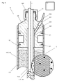
- Figure 1 shows a primary silica (SiO2) tube 11 having a longitudinal axis x, an outer diameter d1, a wall diameter d10, an interior space 12 and a closure 13 at its lower end, which is preferably made as one piece together with the primary silica tube 11.
- the primary silica tube 11 may contain, enclosed in its walls, A/A-material 52 of one or numerous sorts, for purposes that are described below.
- Figure 2 shows the silica tube 11, 11d of figure 1 with an adjoiner 3 at its upper side comprising a first channel 31, through which primary silica grain 51 is filled into the interior space 12 of the silica tube 11.
- Figure 2 further shows different options A, B and C of using a silica tube 11d and primary silica grain 5 that are differently doped with A/A-material 52, thus resulting in different localisations of different selectable A/A-materials 52 within the processed primary preform 1 and consequently in the core of the optical fiber drawn therefrom.
- A/A-material can be RE-material such as Neodymium, Europium, Dysprosium, Holmium, Erbium, Thulium, or Ytterbium or metal, such as Fe, Ni, Co, Cr, Cu, Mn, Ti, and V.
- RE-material such as Neodymium, Europium, Dysprosium, Holmium, Erbium, Thulium, or Ytterbium or metal, such as Fe, Ni, Co, Cr, Cu, Mn, Ti, and V.
- a single sort of material for laser active fibers typically erbium, can be selected. However, depending on the wavelengths of the guided signals, also two ore more sorts of A/A-material can be applied.
- Magnified section A shows the silica tube 11 free from A/A-dopants. Instead several sorts of A/A-dopants 52 are contained in the primary silica grain 51.
- A/A-dopants 52 are contained in the primary silica grain 51.
- different particles of a mixture of A/A-materials are mixed with the silica grain particles. Since A/A-particles typically comprise a small diameter an even distribution of the A/A-particles may be difficult to achieve.
- the A/A-materials are preferably confined within the silica grain, i.e. the A/A-particles are silica cladded.
- Magnified section B of figure 2 shows that both, the primary silica tube 11d and the primary silica grain 51, are doped with different A/A-materials 52 1 , 52 2 .
- Magnified section C of figure 2 shows that only the primary silica tube 11d is doped with the different A/A-materials 52 1 , 52 2 .
- the diameter d10 of the circular wall of the primary silica tube 11, 11d is for example ten times smaller than its outer diameter d1.
- the ratio of said diameters d1/d10 may be up to 50 and higher.
- the volume of the interior space 12 is relatively large, i.e. several times larger than the volume of a conventional primary preform.
- the insertion channel 31 of the adjoiner 3 is closed by a sealing cap 39. Then a vacuum pump 22, that is connected to an evacuation channel 32 provided in the adjoiner 3, removes the air out of the interior space of the primary silica tube 11, 11d, in order to avoid air inclusions in the processed preform 1.
- Figure 3 shows the process of heating, melting and fusing the primary silica grain 51; 51, 52 and the primary silica tube 11, 11d in order to obtain a processed primary preform 1.
- the partially processed primary preform 1 is vertically aligned and mounted in a holding device 21 that allows controlled vertical movement and preferably rotation of the primary preform 1 along and around its axis x.
- the holding device 21 is designed to apply a vibration onto the primary preform 1 in order to condense the primary silica grain 51 provided in the interior space 12 of the primary silica tube 11, 11d.
- Figure 3 further shows a heat supply or furnace 23, which allows heating of the primary preform 1 for example to temperatures in the range of to 2100 °C to 2350 °C. Due to the thermal energy provided by the furnace 23 and due to the established difference of pressures that are present in and outside the preform 1, the primary silica tube 11, 11d and the primary silica grain 51, 52 will melt and fuse together. After the completion of the heating process the primary silica 11, 11d and the primary silica grain 51, 52 will form a practically homogeneous silica body, which however comprises different zones individually doped with A/A-material(s).
- the molten elements can simultaneously be transformed while heating a limited portion, e.g. by drawing a fiber or drawing at least one elongated primary preform 1.
- a limited portion e.g. by drawing a fiber or drawing at least one elongated primary preform 1.
- preforms 1 can be obtained that are tailored to the specific requirements.
- an element drawn from the primary silica tube 11, 11d and the primary silica grain 51, 52 could be used as a fiber or a fiber cavity in a laser system or as a primary preform 1 that is introduced into an unprocessed secondary preform as described below.
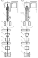
- Figures 4a-4f show the treatment of the heat processed primary preform 1 of figure 3 , during which a peripheral layer is removed, which consists of material derived from the primary silica tube 11.
- Figures 4a and 4b show the processed primary preform 1 of figure 3 after the terminated heating process.
- Figures 4c and 4d show the processed primary preform 1 during the grinding process, preferably executed by an automated grinding tool.
- Figures 4c and 4d show the processed primary preform 1 after the completion of the grinding process, which is recommended to be performed in the event, that the material of the primary silica tube 11 does not favourably contribute to the properties of primary preform 1 or the optical fibers derived therefrom.
- Figures 5a and 5b show the assembly of a secondary preform 10 with a thin-walled secondary silica (SiO2) tube 111 that receives, co-axially aligned, the A/A-doped primary preform 1, 1' of figure 4 (see figure 5a ) and secondary silica grain 510 (see figure 5b ).
- SiO2 thin-walled secondary silica
- Figure 5c shows the assembly of a secondary preform 10' with a thin-walled secondary silica (SiO2) tube 111 that receives, co-axially aligned, an un-doped silica blank 15 and secondary silica grain 510.
- SiO2 thin-walled secondary silica
- the magnified sections D1, D1, D2, D2' and E, E1, E1', E2, E2' show that the secondary silica tube 111 and/or the secondary silica grain 510 can be doped with A/A-material(s) as already described for the primary silica tube 11, 11' and the primary grain 51 in order to obtain the desired properties of the secondary preform 10, 10'.
- Figure 6 shows the upper end of secondary preform 10 from figure 5c , which further comprises a thin walled A/A-doped sleeve tube 11d, e.g. a primary silica tube as shown in figure 1 , that is tightly enclosing the silica blank 15.
- a thin walled A/A-doped sleeve tube 11d e.g. a primary silica tube as shown in figure 1 , that is tightly enclosing the silica blank 15.
- This embodiment of the invention allows bringing A/A-doped material contained in the sleeve tube 11d into the peripheral zone of the silica blank 15.
- the silica blank 15 and the sleeve tube 11d comprise the same refractive index so that a homogeneous silica core can be produced that however comprises zones that are differently doped with A/A-materials 52.
- auxiliary tubes 11x could be provided between the silica blank 15 and the wall auf the secondary silica tube 111 in such a size and number that in average a desired refractive index results from the air or gas enclosed in the auxiliary tubes 11x and the molten secondary silica grain 510.
- the optical signal will travel not only in the center of the core, but also in material of the peripheral regions of the core which are derived from the A/A-doped silica sleeve tube. Since no index step occurs along the radius of the secondary light can pass with reduced losses from the surface of the cladding or from a fiber within the cladding to the center of the core. However the light can most easily reach the peripheral zone of the core.
- Figure 6 further shows a second adjoiner 30 for the secondary preform 10, which comprises a channel 310 that receives the silica blank 15 (or a primary preform 1, 1').
- the secondary silica grain 510 can be introduced for example through the evacuation channel 320, which, after the filling of the secondary silica grain 510 has been completed, is connected via a fitting 221 and a tube 220 to the vacuum pump 22.
- a sealing cap 390 is mounted on top of the adjoiner 30.
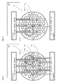
- Figure 7 shows the upper end of the secondary preform 100 that comprises a larger secondary silica tube 111, in which five primary preforms 1, as shown in figure 4 , or five secondary preforms 10, as shown in figure 6 , auxiliary tubes 11x and auxiliary silica rods 15 (or silica blanks) are contained.
- secondary silica grain 510 is inserted into the secondary silica tube 111.
- the secondary silica grain 510 and the secondary silica tube 111 can be doped with A/A-material as required.
- an optical fiber can be drawn that comprises multiple active cores. Elements of the drawn fiber that relate to the auxiliary tubes 11x or to the auxiliary rods 15 can be used for injecting and guiding pump signals as detailed below.
- Figure 8 shows the upper end of the secondary preform 100' that comprises a larger secondary silica tube 111, in which an A/A-doped silica tube 11d, auxiliary tubes 11x and removable auxiliary rods 101 are arranged in a two-dimensional periodic structure.
- a photonic crystal fiber PCF
- the two-dimensional periodic structure is selected to apply the photonic band gap (PBG) effect in the Photonic Crystal Fibre drawn from the processed secondary preform 10.
- PBG photonic band gap
- the removable auxiliary rods 101 serve as space holders within the grain 510 or within an auxiliary tube 11x or within the A/A-doped silica tube 11d.
- relatively thin walled silica tubes preferably of a standard size, can be selected, that will not be deformed or collapse during the heating process.
- the removable rods 101 which are removed after completion of the heating process, keep the interior of the silica tubes 11x, 11d in correct shape.
- a removable rod 101 can be used without an auxiliary tube 11x to maintain a free elongated space within the silica grain. After the preform 100' has been processed the removable rod 1205 is removed.
- Auxiliary rods 101 can easily be removed from vitrified silica, if a material, such as graphite, with a thermal expansion coefficient is used, which is larger than the thermal expansion coefficient of glass. During a cooling process, such a rod 101 will retract or shrink stronger than glass so that will no adhesion remain to the glass. Hence, with removable rods, preforms with complex structures comprising numerous elongated void elements can easily be created.
- Figures 9 shows an apparatus 2 used for drawing an inventive optical fiber 8 from the secondary preform 10, 10' of figure 5 .
- a spinning apparatus 28 which may comprise a roller that imparts a spin into the optical fiber 8.
- the optical fiber 8 then eventually encounters a series of rollers (not shown) pulling the optical fiber 8 before it is then wrapped around a drum or spool 29.
- the secondary preform 10, 10' is mounted in a holding device 21, which allows controlled vertical movement along and preferably rotation around its axis. Furthermore the holding device 21 may be designed to apply a vibration onto the secondary preform in order to condense the secondary silica grain 510.
- Figure 10 shows the apparatus 2 used for drawing an inventive optical fiber 8, such as a photonic crystal fiber, from the secondary preform 100, 100' of figure 7 or figure 8 .
- an inventive optical fiber 8 such as a photonic crystal fiber
- the general principle of optical amplification relies on stimulated emission, as in the laser. A population inversion must first be established between two states, and the stimulated emission boosts the number of in-phase photons.
- Fiber amplifier technology began in 1964 when neodymium was suggested as a suitable element for doping a fiber. A major advance was made in the mid 1980s when erbium was found to produce an optical gain of a few thousand at a wavelength of 1.5 ⁇ m; it integrates well with an InGaAsP light source. Praesodymium-doped fibers are currently being investigated since they operate around 1.3 ⁇ m, the other wavelength used in communication Systems.
- Figure 11 shows a simplified optical amplifier 600 and a sectional view of an inventive active optical fiber 8 that comprises multiple cores 811, 812, ... and auxiliary fibers 811x that originate for example from silica rods or blanks that were provided in the secondary preform 10, 10'.
- Figure 11 shows a source unit 62 that provides pump signals in several wavelengths ⁇ 10, ... , ⁇ 60. These pump signals ⁇ 10, ... , ⁇ 60 are injected in multi mode pump fibers 811x and travel then through the cladding to the cores 81 1 , 81 2 , ... where the RE-ions are exited.
- signals ⁇ 1, ... , ⁇ 7 that are travelling in the cores of the optical fiber 8 will cause stimulated emissions and thus get amplified.
- Figure 12 shows an optical amplifier 600 and a sectional view of an inventive photonic crystal fiber 8'.
- pump signals ⁇ 10, ... , ⁇ 60 are provided to multi mode pump fibers 811x provided in the cladding. From the pump fibers the pump signals reach the peripheral zone of the core region 81RE which relates to the RE-doped silica glass tube 11d. If the periodic structure is slightly disturbed, then the guided user signal, at least the evanescent field will enter this doped peripheral zone and cause stimulated emissions and an amplification of the user signal.
- a major advantage of the present invention is, that the structure of the preforms and thus the structure of the active optical fibers can freely be selected.
- large pump fibers can easily be incorporated which can be identified and opened for the purpose of injection pump signals without interrupting core which guides the user signal.
- the active optical fiber 8 is entered into a sleeve 85, which receives and transfers the pump signals (see figure 14a ).
- the pump signals are transferred with minimal losses if the materials used for the different elements comprise an identical refractive index and the refractive index of the cladding is elevated by means of inclusions of air or gas.
- Figure 13 shows the optical amplifier known form [3] that uses a few windings of an inventive active optical fiber 8 that is spliced (see splicing positions 65) to an optical transmission line 81.
- a weak signal is forwarded from an incoming end of an optical transmission line 81 via an optical isolator 64 and a laser filter 66 to the inventive active optical fiber 8.
- the laser filter 66 blocks pump signals that are generated by a laser source 62 and that are injected into the inventive active optical fiber 8 through a coupling element 63.
- the weak user signal gets amplified in the inventive active optical fiber 8 and is forwarded to the outgoing end of the optical transmission line 81.
- FIG 13 it is shown that not only a single signal, but also a plurality of signals guided in multiple cores could be amplified.
- Figure 14 shows two optical amplifiers 601 which regenerate an optical signal that is guided in an inventive optical fiber, without disturbing the signal path by means of splicing.
- Figure 14 shows the first option of using a pump fiber 811x that has been cut open for injecting a pump signal.
- Figure 14a shows a second option in which a sleeve tube 85 is receiving the optical fiber 8 from which the coating has been removed. Pump signals are then injected via the sleeve tube 85 into the optical fiber 8 for stimulating the RE-ions.
- the preforms described above can be individually be designed, combined or interleaved as required by applicant.
- Inventive primary preforms can be inserted or integrated in a secondary preform.
- Secondary preforms can be integrated in a higher order preform, i.e. a ternary preform which comprises at least one secondary preform.
- the primary or secondary preforms contained in a ternary preform can, as an example, be dedicated to different applications such as the transfer of user signals in different wavelength regions or the transfer of pump signals.
- the lower order e.g.
- primary or secondary, preforms can be inserted into the higher order, e.g. ternary, preform before or after processing, i.e. the performance of the heating process.
- the complete structure of a higher order, e.g. ternary preform, comprising numerous doped or un-doped primary, secondary or higher order silica tubes can however also be established in one step.
- the silica tubes can individually be filled with suitably doped grains in order to obtain desired refractive indices or laser activities in selected zones of the higher order preform.
Landscapes
- Chemical & Material Sciences (AREA)
- Engineering & Computer Science (AREA)
- Physics & Mathematics (AREA)
- Manufacturing & Machinery (AREA)
- Organic Chemistry (AREA)
- Optics & Photonics (AREA)
- General Life Sciences & Earth Sciences (AREA)
- Geochemistry & Mineralogy (AREA)
- Life Sciences & Earth Sciences (AREA)
- Materials Engineering (AREA)
- Crystallography & Structural Chemistry (AREA)
- General Physics & Mathematics (AREA)
- Electromagnetism (AREA)
- Plasma & Fusion (AREA)
- Manufacture, Treatment Of Glass Fibers (AREA)
- Lasers (AREA)
- Glass Compositions (AREA)
Priority Applications (11)
| Application Number | Priority Date | Filing Date | Title |
|---|---|---|---|
| EP06125655A EP1942083A1 (fr) | 2006-12-07 | 2006-12-07 | Procédé et appareil pour la fabrication dýune préforme pour fibre optique active, fibre optique active et amplificateur |
| PCT/EP2007/063519 WO2008068331A1 (fr) | 2006-12-07 | 2007-12-07 | Procédé de fabrication d'une préforme, préforme, fibre optique et amplificateur |
| RU2009125938/03A RU2460696C2 (ru) | 2006-12-07 | 2007-12-07 | Способ изготовления заготовки, заготовка, оптическое волокно и усилитель |
| JP2009539768A JP5574217B2 (ja) | 2006-12-07 | 2007-12-07 | プリフォームを加工する方法 |
| KR1020097011488A KR20090089359A (ko) | 2006-12-07 | 2007-12-07 | 모재 제작방법, 모재, 광섬유 및 증폭기 |
| US12/517,339 US8720230B2 (en) | 2006-12-07 | 2007-12-07 | Method for fabricating an optical fiber preform |
| EP07857292.2A EP2091876B1 (fr) | 2006-12-07 | 2007-12-07 | Procédé pour la fabrication d'une préforme et pour la fabrication d'une fibre optique active |
| BRPI0720006-4A BRPI0720006B1 (pt) | 2006-12-07 | 2007-12-07 | Método para fabricação de uma pré-forma, método para fabricação de uma pré-forma secundária e método para fabricação de uma fibra ótica |
| CN2007800453851A CN101631751B (zh) | 2006-12-07 | 2007-12-07 | 制造预成型坯的方法、预成型坯、光纤和放大器 |
| AU2007330730A AU2007330730B2 (en) | 2006-12-07 | 2007-12-07 | Method for fabricating a preform, a preform, an optical fiber and an amplifier |
| CA2672007A CA2672007C (fr) | 2006-12-07 | 2007-12-07 | Procede de fabrication d'une preforme, preforme, fibre optique et amplificateur |
Applications Claiming Priority (1)
| Application Number | Priority Date | Filing Date | Title |
|---|---|---|---|
| EP06125655A EP1942083A1 (fr) | 2006-12-07 | 2006-12-07 | Procédé et appareil pour la fabrication dýune préforme pour fibre optique active, fibre optique active et amplificateur |
Publications (1)
| Publication Number | Publication Date |
|---|---|
| EP1942083A1 true EP1942083A1 (fr) | 2008-07-09 |
Family
ID=37912460
Family Applications (2)
| Application Number | Title | Priority Date | Filing Date |
|---|---|---|---|
| EP06125655A Withdrawn EP1942083A1 (fr) | 2006-12-07 | 2006-12-07 | Procédé et appareil pour la fabrication dýune préforme pour fibre optique active, fibre optique active et amplificateur |
| EP07857292.2A Active EP2091876B1 (fr) | 2006-12-07 | 2007-12-07 | Procédé pour la fabrication d'une préforme et pour la fabrication d'une fibre optique active |
Family Applications After (1)
| Application Number | Title | Priority Date | Filing Date |
|---|---|---|---|
| EP07857292.2A Active EP2091876B1 (fr) | 2006-12-07 | 2007-12-07 | Procédé pour la fabrication d'une préforme et pour la fabrication d'une fibre optique active |
Country Status (9)
| Country | Link |
|---|---|
| US (1) | US8720230B2 (fr) |
| EP (2) | EP1942083A1 (fr) |
| JP (1) | JP5574217B2 (fr) |
| KR (1) | KR20090089359A (fr) |
| CN (1) | CN101631751B (fr) |
| BR (1) | BRPI0720006B1 (fr) |
| CA (1) | CA2672007C (fr) |
| RU (1) | RU2460696C2 (fr) |
| WO (1) | WO2008068331A1 (fr) |
Families Citing this family (17)
| Publication number | Priority date | Publication date | Assignee | Title |
|---|---|---|---|---|
| EP2261181A1 (fr) | 2009-05-21 | 2010-12-15 | Silitec Fibers SA | Procédé de fabrication et de traitement d'une préforme, préforme et fibre optique |
| EP2261182A1 (fr) * | 2009-05-21 | 2010-12-15 | Silitec Fibers SA | Procédé de fabrication d'une préforme en particules de verre |
| EP2548056B1 (fr) * | 2010-03-16 | 2021-05-05 | OFS Fitel, LLC | Fibres de transmission et d'amplification multicoeur, et schemas pour le lancement d'une lumiere de pompage vers les coeurs d'un amplificateur |
| US20120144869A1 (en) * | 2010-12-10 | 2012-06-14 | Schott Corporation | Glass optical waveguides incorporating materials of interest and methods of fabricating the same |
| US9465166B2 (en) * | 2013-05-29 | 2016-10-11 | Baker Hughes Incorporated | Fiber optic splice protecting system and method for protecting a fiber optic splice |
| US9487428B2 (en) * | 2015-03-06 | 2016-11-08 | Ofs Fitel, Llc | Easy removal of a thin-walled tube in a powder-in-tube (PIT) process |
| CN104788014B (zh) * | 2015-04-12 | 2017-11-24 | 久智光电子材料科技有限公司 | 一种光纤预制棒制备及光纤拉丝的方法 |
| US10126504B2 (en) * | 2015-05-27 | 2018-11-13 | The United States Of America, As Represented By The Secretary Of The Navy | Antireflective surface structures for active and passive optical fiber |
| JP6170968B2 (ja) * | 2015-06-23 | 2017-07-26 | 株式会社フジクラ | 光ファイバ母材の製造方法、及び光ファイバの製造方法 |
| JP6205394B2 (ja) * | 2015-08-03 | 2017-09-27 | 株式会社フジクラ | 光ファイバ母材の製造方法、光ファイバ母材、及び光ファイバの製造方法 |
| CN105403951B (zh) * | 2015-12-22 | 2018-12-28 | 中国工程物理研究院激光聚变研究中心 | 空心-实心复合的多芯光子晶体光纤及其激光放大的方法 |
| CN105607182B (zh) * | 2016-01-06 | 2019-05-24 | 烽火通信科技股份有限公司 | 一种低损耗光子晶体光纤的制备方法 |
| CN108698905A (zh) * | 2016-02-24 | 2018-10-23 | 康宁股份有限公司 | 加工光纤的方法和系统 |
| JP7172088B2 (ja) * | 2018-03-28 | 2022-11-16 | 住友電気工業株式会社 | 光ファイバ製造方法 |
| EP3702333B1 (fr) | 2019-03-01 | 2025-01-22 | Heraeus Quarzglas GmbH & Co. KG | Procédé et dispositif de fabrication d'un composant de verre |
| CN110395901B (zh) * | 2019-07-25 | 2020-04-24 | 武汉库克光电技术有限公司 | 一种高衰减光纤及其制备方法 |
| CN111635127B (zh) * | 2020-05-08 | 2023-06-09 | 江苏永鼎光纤科技有限公司 | 含有功能性石英包层的光纤预制棒及其制备方法 |
Citations (7)
| Publication number | Priority date | Publication date | Assignee | Title |
|---|---|---|---|---|
| JPS5869738A (ja) * | 1981-10-19 | 1983-04-26 | Furukawa Electric Co Ltd:The | 耐放射線光フアイバ |
| GB2176472A (en) * | 1985-06-13 | 1986-12-31 | Heraeus Schott Quarzschmelze | Method for producing a preform mould for optical fibres |
| WO1998058884A1 (fr) * | 1997-06-23 | 1998-12-30 | Corning Incorporated | Composition pour guide d'onde optique et procede de production de filament continu enrobe |
| US6115526A (en) * | 1997-03-27 | 2000-09-05 | Brown University Research Foundation | Ultra high numerical aperture high power optical fiber laser |
| EP1256826A2 (fr) * | 2001-05-10 | 2002-11-13 | FITEL USA CORPORATION (a Delaware Corporation) | Structure de fibre optique pour la transmission sécurisée contre l'écoute illicite |
| US20040196536A1 (en) * | 2003-03-04 | 2004-10-07 | Alcatel | Doped-ring amplifying optical fiber, and an amplifier containing such a fiber |
| WO2005102946A1 (fr) * | 2004-04-27 | 2005-11-03 | Dätwyler Fiber Optics Sa | Procede de fabrication d'une fibre optique, preforme pour fabriquer une fibre optique, fibre optique et dispositif |
Family Cites Families (17)
| Publication number | Priority date | Publication date | Assignee | Title |
|---|---|---|---|---|
| IT1237970B (it) * | 1990-02-07 | 1993-06-19 | Pirelli Cavi Spa | Amplificatore ottico a fibra attiva,con porzioni a doppio nucleo,a larga banda di lunghezza d'onda di segnale |
| CN1026576C (zh) * | 1991-04-30 | 1994-11-16 | 古河电气工业株式会社 | 制造石英玻璃预制件的方法 |
| US5572618A (en) | 1994-07-13 | 1996-11-05 | Lucent Technologies Inc. | Optical attenuator |
| TW371650B (en) * | 1995-12-04 | 1999-10-11 | Sumitomo Electric Industries | Method for producing an optical fiber quartz glass preform |
| GB9713422D0 (en) | 1997-06-26 | 1997-08-27 | Secr Defence | Single mode optical fibre |
| US5907652A (en) * | 1997-09-11 | 1999-05-25 | Lucent Technologies Inc. | Article comprising an air-clad optical fiber |
| US6410471B2 (en) * | 2000-03-07 | 2002-06-25 | Shin-Etsu Chemical Co., Ltd. | Method for preparation of sintered body of rare earth oxide |
| US6711918B1 (en) | 2001-02-06 | 2004-03-30 | Sandia National Laboratories | Method of bundling rods so as to form an optical fiber preform |
| US6690868B2 (en) * | 2001-05-30 | 2004-02-10 | 3M Innovative Properties Company | Optical waveguide article including a fluorine-containing zone |
| WO2003010578A1 (fr) * | 2001-07-12 | 2003-02-06 | Ocg Technology Licensing, Llc | Fibre optique |
| US6723435B1 (en) | 2001-08-28 | 2004-04-20 | Nanogram Corporation | Optical fiber preforms |
| US20040050110A1 (en) * | 2002-08-29 | 2004-03-18 | Berkey George E. | Methods for fabricating optical fibers and optical fiber preforms |
| DE10316487B4 (de) * | 2003-04-09 | 2005-03-31 | Heraeus Tenevo Ag | Verfahren zur Herstellung einer Vorform für optische Fasern |
| US20050079288A1 (en) * | 2003-09-05 | 2005-04-14 | Cornelius Lauren K. | Suppressing mono-valent metal ion migration using alumina-containing barrier layer |
| US7403689B2 (en) | 2003-11-19 | 2008-07-22 | Corning Incorporated | Active photonic band-gap optical fiber |
| JP4561314B2 (ja) * | 2004-10-28 | 2010-10-13 | 日立電線株式会社 | ファイバレーザ用光ファイバ、ファイバレーザ及びレーザ発振方法 |
| US7072552B2 (en) | 2004-12-02 | 2006-07-04 | Nufern | Optical fiber with micro-structured cladding |
-
2006
- 2006-12-07 EP EP06125655A patent/EP1942083A1/fr not_active Withdrawn
-
2007
- 2007-12-07 WO PCT/EP2007/063519 patent/WO2008068331A1/fr not_active Ceased
- 2007-12-07 JP JP2009539768A patent/JP5574217B2/ja not_active Expired - Fee Related
- 2007-12-07 KR KR1020097011488A patent/KR20090089359A/ko not_active Ceased
- 2007-12-07 EP EP07857292.2A patent/EP2091876B1/fr active Active
- 2007-12-07 US US12/517,339 patent/US8720230B2/en active Active
- 2007-12-07 RU RU2009125938/03A patent/RU2460696C2/ru active
- 2007-12-07 BR BRPI0720006-4A patent/BRPI0720006B1/pt not_active IP Right Cessation
- 2007-12-07 CN CN2007800453851A patent/CN101631751B/zh not_active Expired - Fee Related
- 2007-12-07 CA CA2672007A patent/CA2672007C/fr active Active
Patent Citations (8)
| Publication number | Priority date | Publication date | Assignee | Title |
|---|---|---|---|---|
| JPS5869738A (ja) * | 1981-10-19 | 1983-04-26 | Furukawa Electric Co Ltd:The | 耐放射線光フアイバ |
| GB2176472A (en) * | 1985-06-13 | 1986-12-31 | Heraeus Schott Quarzschmelze | Method for producing a preform mould for optical fibres |
| US6115526A (en) * | 1997-03-27 | 2000-09-05 | Brown University Research Foundation | Ultra high numerical aperture high power optical fiber laser |
| WO1998058884A1 (fr) * | 1997-06-23 | 1998-12-30 | Corning Incorporated | Composition pour guide d'onde optique et procede de production de filament continu enrobe |
| EP1256826A2 (fr) * | 2001-05-10 | 2002-11-13 | FITEL USA CORPORATION (a Delaware Corporation) | Structure de fibre optique pour la transmission sécurisée contre l'écoute illicite |
| US20040196536A1 (en) * | 2003-03-04 | 2004-10-07 | Alcatel | Doped-ring amplifying optical fiber, and an amplifier containing such a fiber |
| WO2005102946A1 (fr) * | 2004-04-27 | 2005-11-03 | Dätwyler Fiber Optics Sa | Procede de fabrication d'une fibre optique, preforme pour fabriquer une fibre optique, fibre optique et dispositif |
| WO2005102947A1 (fr) * | 2004-04-27 | 2005-11-03 | Dätwyler Fiber Optics S.A. | Fibre optique et preforme de celle-ci ainsi que les procede et appareil de fabrication correspondants |
Also Published As
| Publication number | Publication date |
|---|---|
| EP2091876B1 (fr) | 2020-08-19 |
| BRPI0720006A2 (pt) | 2013-12-17 |
| CA2672007C (fr) | 2013-08-27 |
| JP5574217B2 (ja) | 2014-08-20 |
| US8720230B2 (en) | 2014-05-13 |
| US20100000260A1 (en) | 2010-01-07 |
| CN101631751B (zh) | 2013-09-25 |
| AU2007330730A1 (en) | 2008-06-12 |
| BRPI0720006B1 (pt) | 2019-02-19 |
| CA2672007A1 (fr) | 2008-06-12 |
| KR20090089359A (ko) | 2009-08-21 |
| RU2009125938A (ru) | 2011-01-20 |
| EP2091876A1 (fr) | 2009-08-26 |
| CN101631751A (zh) | 2010-01-20 |
| RU2460696C2 (ru) | 2012-09-10 |
| JP2010511588A (ja) | 2010-04-15 |
| WO2008068331A1 (fr) | 2008-06-12 |
Similar Documents
| Publication | Publication Date | Title |
|---|---|---|
| US8720230B2 (en) | Method for fabricating an optical fiber preform | |
| EP2292566B1 (fr) | Fibres optiques dopées par des terres rares et fibres optiques à grande surface efficace pour lasers à fibre et amplificateurs | |
| US10838141B2 (en) | Spun round core fiber | |
| EP2460036B1 (fr) | Fibres optiques à c ur formé avec précision, et procédé de fabrication | |
| US7835608B2 (en) | Method and apparatus for optical delivery fiber having cladding with absorbing regions | |
| US8958674B2 (en) | Amplifying optical fiber and production method | |
| US7657142B2 (en) | Method for making an optical fiber comprising nanoparticles and preform used in the manufacture of such a fiber | |
| AU2007330730B2 (en) | Method for fabricating a preform, a preform, an optical fiber and an amplifier | |
| US8116607B2 (en) | Rare-earth doped optical fiber, method of producing the same, and fiber laser | |
| Kim | Hollow optical fibers and W-type fibers for high power sources and suppression of the stimulated Raman scattering |
Legal Events
| Date | Code | Title | Description |
|---|---|---|---|
| PUAI | Public reference made under article 153(3) epc to a published international application that has entered the european phase |
Free format text: ORIGINAL CODE: 0009012 |
|
| AK | Designated contracting states |
Kind code of ref document: A1 Designated state(s): AT BE BG CH CY CZ DE DK EE ES FI FR GB GR HU IE IS IT LI LT LU LV MC NL PL PT RO SE SI SK TR |
|
| AX | Request for extension of the european patent |
Extension state: AL BA HR MK RS |
|
| AKX | Designation fees paid | ||
| REG | Reference to a national code |
Ref country code: DE Ref legal event code: 8566 |
|
| STAA | Information on the status of an ep patent application or granted ep patent |
Free format text: STATUS: THE APPLICATION IS DEEMED TO BE WITHDRAWN |
|
| 18D | Application deemed to be withdrawn |
Effective date: 20090112 |