EP1944475A2 - Heat exchange system - Google Patents
Heat exchange system Download PDFInfo
- Publication number
- EP1944475A2 EP1944475A2 EP08250063A EP08250063A EP1944475A2 EP 1944475 A2 EP1944475 A2 EP 1944475A2 EP 08250063 A EP08250063 A EP 08250063A EP 08250063 A EP08250063 A EP 08250063A EP 1944475 A2 EP1944475 A2 EP 1944475A2
- Authority
- EP
- European Patent Office
- Prior art keywords
- flap
- exit
- entrance
- engine
- duct
- Prior art date
- Legal status (The legal status is an assumption and is not a legal conclusion. Google has not performed a legal analysis and makes no representation as to the accuracy of the status listed.)
- Granted
Links
- 238000001816 cooling Methods 0.000 claims abstract description 45
- 239000012530 fluid Substances 0.000 claims abstract description 19
- 230000001050 lubricating effect Effects 0.000 claims abstract description 4
- 239000010687 lubricating oil Substances 0.000 claims description 20
- 239000000314 lubricant Substances 0.000 claims description 17
- 238000005461 lubrication Methods 0.000 claims description 9
- 238000011144 upstream manufacturing Methods 0.000 claims description 6
- 238000000034 method Methods 0.000 claims 5
- 239000000446 fuel Substances 0.000 description 9
- 239000003921 oil Substances 0.000 description 8
- 238000010438 heat treatment Methods 0.000 description 2
- 230000000694 effects Effects 0.000 description 1
- 238000011084 recovery Methods 0.000 description 1
- 238000010792 warming Methods 0.000 description 1
Images


Classifications
-
- F—MECHANICAL ENGINEERING; LIGHTING; HEATING; WEAPONS; BLASTING
- F01—MACHINES OR ENGINES IN GENERAL; ENGINE PLANTS IN GENERAL; STEAM ENGINES
- F01D—NON-POSITIVE DISPLACEMENT MACHINES OR ENGINES, e.g. STEAM TURBINES
- F01D25/00—Component parts, details, or accessories, not provided for in, or of interest apart from, other groups
- F01D25/08—Cooling; Heating; Heat-insulation
- F01D25/12—Cooling
-
- F—MECHANICAL ENGINEERING; LIGHTING; HEATING; WEAPONS; BLASTING
- F01—MACHINES OR ENGINES IN GENERAL; ENGINE PLANTS IN GENERAL; STEAM ENGINES
- F01D—NON-POSITIVE DISPLACEMENT MACHINES OR ENGINES, e.g. STEAM TURBINES
- F01D25/00—Component parts, details, or accessories, not provided for in, or of interest apart from, other groups
- F01D25/18—Lubricating arrangements
-
- F—MECHANICAL ENGINEERING; LIGHTING; HEATING; WEAPONS; BLASTING
- F02—COMBUSTION ENGINES; HOT-GAS OR COMBUSTION-PRODUCT ENGINE PLANTS
- F02C—GAS-TURBINE PLANTS; AIR INTAKES FOR JET-PROPULSION PLANTS; CONTROLLING FUEL SUPPLY IN AIR-BREATHING JET-PROPULSION PLANTS
- F02C7/00—Features, components parts, details or accessories, not provided for in, or of interest apart form groups F02C1/00 - F02C6/00; Air intakes for jet-propulsion plants
- F02C7/12—Cooling of plants
- F02C7/14—Cooling of plants of fluids in the plant, e.g. lubricant or fuel
-
- F—MECHANICAL ENGINEERING; LIGHTING; HEATING; WEAPONS; BLASTING
- F02—COMBUSTION ENGINES; HOT-GAS OR COMBUSTION-PRODUCT ENGINE PLANTS
- F02C—GAS-TURBINE PLANTS; AIR INTAKES FOR JET-PROPULSION PLANTS; CONTROLLING FUEL SUPPLY IN AIR-BREATHING JET-PROPULSION PLANTS
- F02C9/00—Controlling gas-turbine plants; Controlling fuel supply in air- breathing jet-propulsion plants
- F02C9/16—Control of working fluid flow
- F02C9/18—Control of working fluid flow by bleeding, bypassing or acting on variable working fluid interconnections between turbines or compressors or their stages
-
- F—MECHANICAL ENGINEERING; LIGHTING; HEATING; WEAPONS; BLASTING
- F02—COMBUSTION ENGINES; HOT-GAS OR COMBUSTION-PRODUCT ENGINE PLANTS
- F02K—JET-PROPULSION PLANTS
- F02K3/00—Plants including a gas turbine driving a compressor or a ducted fan
- F02K3/08—Plants including a gas turbine driving a compressor or a ducted fan with supplementary heating of the working fluid; Control thereof
- F02K3/105—Heating the by-pass flow
- F02K3/115—Heating the by-pass flow by means of indirect heat exchange
-
- F—MECHANICAL ENGINEERING; LIGHTING; HEATING; WEAPONS; BLASTING
- F05—INDEXING SCHEMES RELATING TO ENGINES OR PUMPS IN VARIOUS SUBCLASSES OF CLASSES F01-F04
- F05D—INDEXING SCHEME FOR ASPECTS RELATING TO NON-POSITIVE-DISPLACEMENT MACHINES OR ENGINES, GAS-TURBINES OR JET-PROPULSION PLANTS
- F05D2240/00—Components
- F05D2240/10—Stators
- F05D2240/12—Fluid guiding means, e.g. vanes
-
- F—MECHANICAL ENGINEERING; LIGHTING; HEATING; WEAPONS; BLASTING
- F05—INDEXING SCHEMES RELATING TO ENGINES OR PUMPS IN VARIOUS SUBCLASSES OF CLASSES F01-F04
- F05D—INDEXING SCHEME FOR ASPECTS RELATING TO NON-POSITIVE-DISPLACEMENT MACHINES OR ENGINES, GAS-TURBINES OR JET-PROPULSION PLANTS
- F05D2250/00—Geometry
- F05D2250/50—Inlet or outlet
- F05D2250/52—Outlet
-
- Y—GENERAL TAGGING OF NEW TECHNOLOGICAL DEVELOPMENTS; GENERAL TAGGING OF CROSS-SECTIONAL TECHNOLOGIES SPANNING OVER SEVERAL SECTIONS OF THE IPC; TECHNICAL SUBJECTS COVERED BY FORMER USPC CROSS-REFERENCE ART COLLECTIONS [XRACs] AND DIGESTS
- Y02—TECHNOLOGIES OR APPLICATIONS FOR MITIGATION OR ADAPTATION AGAINST CLIMATE CHANGE
- Y02T—CLIMATE CHANGE MITIGATION TECHNOLOGIES RELATED TO TRANSPORTATION
- Y02T50/00—Aeronautics or air transport
- Y02T50/60—Efficient propulsion technologies, e.g. for aircraft
Definitions
- the present invention relates to lubrication systems for turbine engines and for associated equipment, and more particularly, to air and lubricant heat exchangers for use in maintaining desired temperatures of the lubricants in such engines and equipment.
- Lubrication systems for turbine engines such as a turbofan engine, and for associated equipment, such as an integrated drive generator, provide pressurized lubricant, an oil, to lubricate, cool and clean the engine main bearings, gear box gears, and the like, and again for the lubrication of bearings and other parts in equipment associated with such turbine engines.
- heating of the lubricant is caused to occur due to mechanical energy losses in the lubricated apparatus.
- Thermal management of such lubricants is very important for continued successful operation of such lubrication systems in the apparatus lubricated thereby.
- the lubrication system for a turbofan engine in an aircraft typically has a first heat exchanger having passageways through which lubricating oil passes to be cooled by the fuel stream flowing past and around these passageways.
- This arrangement permits the lubricating oil to reject heat therein to the fuel in the aircraft thereby heating that fuel to help recover some of the energy lost in the combustor of the engine.
- a portion of the lubricating oil can be forced to bypass the heat exchanger for the fuel and the lubricating oil, and the oil can be directed to a further heat exchanger where the heat therein is transferred to the air in the secondary airstream provided by the fan of the turbofan engine.
- a duct is provided in the fan cowling through which a portion of the airstream is diverted, and the air and lubricating oil heat exchanger is placed in this duct so that the lubricating oil passing through passageways in that heat exchanger is cooled by the duct airstream flowing past these passageways in the exchanger. If such additional cooling of the oil is not needed in a flight situation, the lubricating oil can again be forced to bypass this air and lubricating oil heat exchanger.
- the fan airstream that is diverted to pass through the lubricating oil and air heat exchanger in such duct systems flows at least in part through that exchanger, and the exchanger should be large enough, insofar as assuring that a sufficient part of the cooling engine fan airstream flows over a sufficient amount of lubricating oil flowing in passageways therein, to provide adequate oil cooling for the most extreme flight conditions encountered.
- Larger heat exchangers require larger cross sectional area ducts, and such an air and lubricating oil heat exchanger duct based system continually leads to thrust losses in the turbofan engine.
- an air and lubricating oil heat exchanger duct based system that reduces such thrust losses and also reduces the volume required therefor in the more compact spaces in advanced turbofan engines.
- the present invention provides in one aspect a heat exchange system for use in operating equipment in which a working fluid is utilized in providing selected operations thereof, the heat exchange system providing air and working fluid heat exchanges to cool the working fluid at selectively variable rates in airstreams occurring with uses of the equipment.
- the system has a cooling duct extending through at least a portion of a stream structure that is positioned providing access to the airstreams occurring during use, with the cooling duct having an entrance opening on an upstream side and an exit opening on a downstream side.
- a moveable entrance flap can be disposed on the upstream side of the cooling duct such that the moveable entrance flap covers at least a portion of the entrance opening when in a closed position that permits flow of air through the cooling duct when in an open position, and a moveable exit flap is disposed on the downstream side of the cooling duct such that the moveable exit flap covers at least a portion of the exit opening when in a closed position that permits flow of air through the cooling duct when in an open position.
- a heat exchanger core is provided in the cooling duct between the entrance and exit openings thereof, and has a plurality of passageway structures therein about which air can pass in flowing therethrough with the passageway structures being coupled to an input conduit at one end thereof and coupled to an output conduit at an opposite end thereof to enable the working fluid to be provided, and removed from, interiors of the passageway structures through interiors of the input and output conduits.
- a smaller cross sectional area heat exchanger leads to enabling its use in a duct of a smaller cross sectional area to thereby improve the compactness of the resulting cooling subsystem.
- Achieving the same cooling of a working fluid, such as a lubricant, passing through such a smaller cross sectional area heat exchanger generally requires that a larger volume of air pass through that heat exchanger per unit time about the passageways thereof to which the working fluid is delivered and through which the previously heated working fluid is flowing to be cooled.
- the working fluid cooled in those passageways is thereafter subsequently be introduced to the remainder of the system making use of that fluid.
- locating the duct in the engine nacelle lower bifurcation, or in some other engine nacelle bifurcation or in the engine core or outer cowlings, to extend from an upstream side near the engine fan to a downstream side at about the end or past the end of the engine fan stream nozzle can provide a significantly greater airflow through that duct to thereby allow reducing the duct cross sectional area and that of the air and lubricant heat exchanger contained therein.
- the air and lubricant heat exchanger may not be needed, or may not be needed to its full cooling capacity.
- This situation allows the air flow through the duct to be reduced by providing a duct exit flap that can be controlled to provide the desired cross sectional area for the duct exit, an area that can be kept to the allowable area needed for sufficient lubricant cooling to thereby increase the thrust produced by the escaping air at the duct exit.
- a duct entrance flap is also provided, typically allowing a duct entrance cross sectional area that is half again as large as the duct exit cross sectional area being then currently provided by the duct exit flap, but which closes the duct entrance if the duct exit flap has closed the duct exit to thereby reduce the drag due to the duct.
- These two flaps can be commonly controlled insofar as setting the corresponding duct cross sectional openings by using a single flap actuator operating a proportional linkage joining the two flaps, by an actuator for each of these flaps operated by a common actuator controller (not shown) or by any other means that can effect movement of either one of the flaps or both of the flaps.
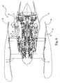
- FIG. 1 there is shown a top view of a fan duct lower bifurcation structure, 10, having an airstream cooling duct, 11, beginning upstream at a duct inlet, 12, and extending from there in this structure over a portion of its length downstream to an exit location to extend through a portion of the interior of bifurcation structure 10.
- Airstream 13 flows about, and then past, those tubes to reach an exit, 16, of duct 11 at its downstream end which has an exit cross sectional area that is controlled in magnitude by an exit flap, 16'.
- Entrance flap 12' can be selectively rotated forcibly inward or outward from the position thereof shown in Figure 1
- exit flap 16N can be selectively rotated forcibly inward or outward from the position thereof shown in that figure, by angle positioning motor, 17, causing a proportional linkage arrangement, 17' to correspondingly move these flaps, and the linkage components, about pins shown in bold dark circles and about the shaft coupled to that motor.
- entrance flap 12' can be so selectively rotated
- exit flap 16' can be so selectively rotated, by a corresponding one a pair of angle positioning motors, 17" and 17"', directly coupled thereto by corresponding shafts.
- flap 12' may be omitted.
- Bifurcation structure 10 is positioned between the bottom of the wall of an engine core cowling, 18, and the bottom of the wall of an outer cowling, 19, of the engine pod for a turbofan engine, 20, as indicated in the partially cut away views shown in Figures 2 and 3 in which only a portion of outer cowling 19 is shown. Shown in turbofan engine 20 among other components is the fan, 21, and the fan duct nozzle, 22, with the fan duct extending therebetween.
- Figure 2 provides a representation of fan duct lower bifurcation structure 10 including airstream duct 11 with flaps 12' and 16' to be operated by angle positioning actuator or motor 17 directing proportional linkage arrangement 17'.
- Figure 3 alternatively provides a representation of fan duct lower bifurcation structure 10 including airstream duct 11 with flaps 12' and 16' to be directly operated by angle positioning actuators or motors 17" and 17"', respectively.
- Figure 4 shows a lengthened bifurcation structure, 10', extending past fan duct nozzle 22, and so outside of the turbofan engine fan duct into the atmosphere, and so fan duct nozzle 22 is configured to be capable of closing against, or nearly closing against, the wall of structure 10 to close, or nearly close, off the fan duct.
- duct structure 11 can be provided again with its input 12 in the fan airstream but then extending either through outer cowling 18, as in Figure 5 , or through engine core cowling 19 to extend through a portion of the engine compartment about which core cowling 19 is provided and back out of core cowling 19 to the atmosphere as shown in Figure 6 .
- Outer cowling 19 is shown in full cross section in Figures 5 and 6 .
- Ducts 11 in each of these figures are shown with exit flap 16' present and operated by angle positioning actuator or motor 17"' to control the amount of exit 16 that is open to the atmosphere during engine operation.
- flap 16' This control of flap 16' by a suitable controller (not shown) sets the degree of cooling of the oil in tubes 15 of air and oil heat exchanger 14 and the amount of thrust recovery.
- Devices other than flaps can be used to selectively reduce the area of exit opening 16 such as a variable area nozzle.
- a duct entrance opening flap, or other entrance opening selective opening area actuator can be provided at duct opening 12 in the ducts of Figures 5 and 6 .
- entrance opening flap, or other entrance opening selective opening area actuator can be provided at duct opening 12 in the ducts of Figures 5 and 6 .
Landscapes
- Engineering & Computer Science (AREA)
- Mechanical Engineering (AREA)
- General Engineering & Computer Science (AREA)
- Chemical & Material Sciences (AREA)
- Combustion & Propulsion (AREA)
- Physics & Mathematics (AREA)
- Fluid Mechanics (AREA)
- Structures Of Non-Positive Displacement Pumps (AREA)
- Incineration Of Waste (AREA)
Abstract
Description
- The present invention relates to lubrication systems for turbine engines and for associated equipment, and more particularly, to air and lubricant heat exchangers for use in maintaining desired temperatures of the lubricants in such engines and equipment.
- Lubrication systems for turbine engines, such as a turbofan engine, and for associated equipment, such as an integrated drive generator, provide pressurized lubricant, an oil, to lubricate, cool and clean the engine main bearings, gear box gears, and the like, and again for the lubrication of bearings and other parts in equipment associated with such turbine engines. During such lubrications, heating of the lubricant is caused to occur due to mechanical energy losses in the lubricated apparatus. Thermal management of such lubricants is very important for continued successful operation of such lubrication systems in the apparatus lubricated thereby.
- The amount of heat necessary to be ejected from lubricants in such systems is increasing because of the use of larger electrical generators, for instance, in aircraft turbine engines due to increasing consumption of electrical power in the aircraft powered thereby, and because of the advances in aircraft turbine engines such as the use of geared turbofans for such aircraft with large fan-drive gearboxes. Despite the added heat generated by such modified and expanded equipment, the necessary lubricating oil operating temperature ranges to provide satisfactory lubricating performance have not changed for the most part and, in some instances, the upper operating temperature limits have been reduced.
- The lubrication system for a turbofan engine in an aircraft typically has a first heat exchanger having passageways through which lubricating oil passes to be cooled by the fuel stream flowing past and around these passageways. This arrangement permits the lubricating oil to reject heat therein to the fuel in the aircraft thereby heating that fuel to help recover some of the energy lost in the combustor of the engine. Because in some flight situations more heat is generated in the lubricating oil than can be accepted for warming the fuel, a portion of the lubricating oil can be forced to bypass the heat exchanger for the fuel and the lubricating oil, and the oil can be directed to a further heat exchanger where the heat therein is transferred to the air in the secondary airstream provided by the fan of the turbofan engine. In a typical arrangement, a duct is provided in the fan cowling through which a portion of the airstream is diverted, and the air and lubricating oil heat exchanger is placed in this duct so that the lubricating oil passing through passageways in that heat exchanger is cooled by the duct airstream flowing past these passageways in the exchanger. If such additional cooling of the oil is not needed in a flight situation, the lubricating oil can again be forced to bypass this air and lubricating oil heat exchanger.
- However, the fan airstream that is diverted to pass through the lubricating oil and air heat exchanger in such duct systems flows at least in part through that exchanger, and the exchanger should be large enough, insofar as assuring that a sufficient part of the cooling engine fan airstream flows over a sufficient amount of lubricating oil flowing in passageways therein, to provide adequate oil cooling for the most extreme flight conditions encountered. Larger heat exchangers require larger cross sectional area ducts, and such an air and lubricating oil heat exchanger duct based system continually leads to thrust losses in the turbofan engine. Hence, there is a strong desire for an air and lubricating oil heat exchanger duct based system that reduces such thrust losses and also reduces the volume required therefor in the more compact spaces in advanced turbofan engines.
- The present invention provides in one aspect a heat exchange system for use in operating equipment in which a working fluid is utilized in providing selected operations thereof, the heat exchange system providing air and working fluid heat exchanges to cool the working fluid at selectively variable rates in airstreams occurring with uses of the equipment. The system has a cooling duct extending through at least a portion of a stream structure that is positioned providing access to the airstreams occurring during use, with the cooling duct having an entrance opening on an upstream side and an exit opening on a downstream side. A moveable entrance flap can be disposed on the upstream side of the cooling duct such that the moveable entrance flap covers at least a portion of the entrance opening when in a closed position that permits flow of air through the cooling duct when in an open position, and a moveable exit flap is disposed on the downstream side of the cooling duct such that the moveable exit flap covers at least a portion of the exit opening when in a closed position that permits flow of air through the cooling duct when in an open position. A heat exchanger core is provided in the cooling duct between the entrance and exit openings thereof, and has a plurality of passageway structures therein about which air can pass in flowing therethrough with the passageway structures being coupled to an input conduit at one end thereof and coupled to an output conduit at an opposite end thereof to enable the working fluid to be provided, and removed from, interiors of the passageway structures through interiors of the input and output conduits.
-
-
Figure 1 shows a cross sectional top view representation of a turbofan engine fan duct lower bifurcation structure embodying the present invention, -
Figure 2 shows a side view partially cut away of a turbofan engine and a further representation of the turbofan engine fan duct lower bifurcation structure ofFigure 1 embodying the present invention, -
Figure 3 shows a side view partially cut away of a turbofan engine and a further representation of the turbofan engine fan duct lower bifurcation structure ofFigure 1 embodying an alternative version of the present invention, -
Figure 4 shows a side view partially cut away of a turbofan engine and a further representation of the turbofan engine fan duct lower bifurcation structure ofFigure 1 embodying an alternative version of the present invention, -
Figure 5 shows a side view partially cut away of a turbofan engine and a representation of the turbofan engine fan duct cowling structure embodying an alternative version of the present invention, and -
Figure 6 shows a side view partially cut away of a turbofan engine and another representation of the turbofan engine fan duct cowling structure embodying an alternative version of the present invention. - A smaller cross sectional area heat exchanger leads to enabling its use in a duct of a smaller cross sectional area to thereby improve the compactness of the resulting cooling subsystem. Achieving the same cooling of a working fluid, such as a lubricant, passing through such a smaller cross sectional area heat exchanger generally requires that a larger volume of air pass through that heat exchanger per unit time about the passageways thereof to which the working fluid is delivered and through which the previously heated working fluid is flowing to be cooled. The working fluid cooled in those passageways is thereafter subsequently be introduced to the remainder of the system making use of that fluid. Such an increase in volume rate of air passing through the heat exchanger in a smaller cross sectional area duct generally requires that the pressure gradient from the duct entrance to the duct exit be sufficiently greater to result in such a flow. Although the present invention is useable with any working fluid provided in connection with a gas turbine engine that needs cooling, the remainder of the specification will describe an embodiment in which the working fluid is a lubricant.
- A relatively large pressure gradient exists in a turbofan engine between the beginning of the fan stream in the turbofan engine and the ambient atmosphere. Thus, locating the duct in the engine nacelle lower bifurcation, or in some other engine nacelle bifurcation or in the engine core or outer cowlings, to extend from an upstream side near the engine fan to a downstream side at about the end or past the end of the engine fan stream nozzle can provide a significantly greater airflow through that duct to thereby allow reducing the duct cross sectional area and that of the air and lubricant heat exchanger contained therein.
- In addition, if the temperature of the engine fuel from its source is low enough to allow the fuel to absorb sufficient heat from the lubricant in the fuel and lubricant heat exchanger in the engine fuel system, the air and lubricant heat exchanger may not be needed, or may not be needed to its full cooling capacity. This situation allows the air flow through the duct to be reduced by providing a duct exit flap that can be controlled to provide the desired cross sectional area for the duct exit, an area that can be kept to the allowable area needed for sufficient lubricant cooling to thereby increase the thrust produced by the escaping air at the duct exit. Often, a duct entrance flap is also provided, typically allowing a duct entrance cross sectional area that is half again as large as the duct exit cross sectional area being then currently provided by the duct exit flap, but which closes the duct entrance if the duct exit flap has closed the duct exit to thereby reduce the drag due to the duct. These two flaps can be commonly controlled insofar as setting the corresponding duct cross sectional openings by using a single flap actuator operating a proportional linkage joining the two flaps, by an actuator for each of these flaps operated by a common actuator controller (not shown) or by any other means that can effect movement of either one of the flaps or both of the flaps.
- Thus, in
Figure 1 , there is shown a top view of a fan duct lower bifurcation structure, 10, having an airstream cooling duct, 11, beginning upstream at a duct inlet, 12, and extending from there in this structure over a portion of its length downstream to an exit location to extend through a portion of the interior ofbifurcation structure 10. An airstream, 13, from a portion of the turbofan engine fan airstream, or fan stream, entersduct 11 atinlet 12 controlled by a duct entrance flap, 12', to pass through a heat exchanger, 14, that usesairstream 13 to cool lubricating oil in the engine lubrication system forced under pressure through a plurality of oil carrying tubes, 15, that are suitably connected into the lubrication system by being connected at one end to an input conduit and at the opposite end to an output conduit so as to allow lubricant oil therein to flow through these tubes. Airstream 13 flows about, and then past, those tubes to reach an exit, 16, ofduct 11 at its downstream end which has an exit cross sectional area that is controlled in magnitude by an exit flap, 16'. - Entrance flap 12' can be selectively rotated forcibly inward or outward from the position thereof shown in
Figure 1 , and exit flap 16N can be selectively rotated forcibly inward or outward from the position thereof shown in that figure, by angle positioning motor, 17, causing a proportional linkage arrangement, 17' to correspondingly move these flaps, and the linkage components, about pins shown in bold dark circles and about the shaft coupled to that motor. Alternatively, entrance flap 12' can be so selectively rotated, and exit flap 16' can be so selectively rotated, by a corresponding one a pair of angle positioning motors, 17" and 17"', directly coupled thereto by corresponding shafts. In turbofan engines that have the airstreams in the fan duct of a sufficiently small Mach number, flap 12' may be omitted. -
Bifurcation structure 10 is positioned between the bottom of the wall of an engine core cowling, 18, and the bottom of the wall of an outer cowling, 19, of the engine pod for a turbofan engine, 20, as indicated in the partially cut away views shown inFigures 2 and3 in which only a portion ofouter cowling 19 is shown. Shown inturbofan engine 20 among other components is the fan, 21, and the fan duct nozzle, 22, with the fan duct extending therebetween.Figure 2 provides a representation of fan ductlower bifurcation structure 10 includingairstream duct 11 with flaps 12' and 16' to be operated by angle positioning actuator ormotor 17 directing proportional linkage arrangement 17'. -
Figure 3 alternatively provides a representation of fan ductlower bifurcation structure 10 includingairstream duct 11 with flaps 12' and 16' to be directly operated by angle positioning actuators ormotors 17" and 17"', respectively. In contrast toFigures 2 and3 ,Figure 4 shows a lengthened bifurcation structure, 10', extending pastfan duct nozzle 22, and so outside of the turbofan engine fan duct into the atmosphere, and sofan duct nozzle 22 is configured to be capable of closing against, or nearly closing against, the wall ofstructure 10 to close, or nearly close, off the fan duct. - Alternative to the providing of the
heat exchanger duct 11 inbifurcation structures 10 or 10',duct structure 11 can be provided again with itsinput 12 in the fan airstream but then extending either throughouter cowling 18, as inFigure 5 , or through engine core cowling 19 to extend through a portion of the engine compartment about whichcore cowling 19 is provided and back out of core cowling 19 to the atmosphere as shown inFigure 6 .Outer cowling 19 is shown in full cross section inFigures 5 and6 .Ducts 11 in each of these figures are shown with exit flap 16' present and operated by angle positioning actuator ormotor 17"' to control the amount ofexit 16 that is open to the atmosphere during engine operation. This control of flap 16' by a suitable controller (not shown) sets the degree of cooling of the oil intubes 15 of air andoil heat exchanger 14 and the amount of thrust recovery. Devices other than flaps can be used to selectively reduce the area ofexit opening 16 such as a variable area nozzle. Also, a duct entrance opening flap, or other entrance opening selective opening area actuator, can be provided at duct opening 12 in the ducts ofFigures 5 and6 . entrance opening flap, or other entrance opening selective opening area actuator, can be provided at duct opening 12 in the ducts ofFigures 5 and6 . - Although the present invention has been described with reference to preferred embodiments, workers skilled in the art will recognize that changes may be made in form and detail without departing from the scope of the invention.
Claims (21)
- A heat exchange system for use in operating equipment in which a working fluid is utilized in providing selected operations thereof, the heat exchange system providing air and working fluid heat exchanges to cool the working fluid at selectively variable rates in airstreams occurring with uses of the equipment, the system comprising:a cooling duct (11) extending through at least a portion of a stream structure that is positioned providing access to the airstreams occurring during use, the cooling duct (11) having an entrance opening (12) on an upstream side and an exit opening (16) on a downstream side;a moveable entrance flap (12') disposed on the upstream side of the cooling duct (11) such that the moveable entrance flap (12') covers at least a portion of the entrance opening (12) when in a closed position and permits flow of air through the cooling duct (11) when in an open position;a moveable exit flap (16') disposed on the downstream side of the cooling duct (11) such that the moveable exit flap (16') covers at least a portion of the exit opening (16) when in a closed position and permits flow of air through the cooling duct (11) when in an open position; anda heat exchanger core (14) provided in the cooling duct (11) between the entrance and exit openings (12,16) thereof and having a plurality of passageway structures (15) therein about which air can pass in flowing therethrough with the passageway structures (15) being coupled to an input conduit at one end thereof and coupled to an output conduit at an opposite end thereof to enable the working fluid to be provided, and removed from, interiors of the passageway structures (15) through interiors of the input and output conduits.
- The system of claim 1 wherein said stream structure is a selected one of a) a portion of an engine core cowling (18) about the engine compartment for a turbofan engine (20) with the end of the cooling duct (11) located about at or outside of the end of the fan duct nozzle (22) of the turbofan engine (20), and b) a portion of the outer cowling (19) of an engine pod for a turbofan engine (20).
- The system of claim 1 wherein said stream structure is a fan duct lower bifurcation structure (10) positioned between the bottom of the wall of an engine core cowling (18) about the engine compartment and the inside of the outer cowling (19) of an engine pod for a turbofan engine (20) with the end of the cooling duct (11) located about at or outside of the end of the fan duct nozzle of the turbofan engine.
- The system of claim 2 wherein the cooling duct (11) extends through the engine core cowling (18) at a first location to from there extend through a portion of the engine compartment about which the engine core cowling (18) is provided and to then again extend through engine core cowling (18) at a second location.
- The system of any preceding claim wherein the entrance flap (12') is positioned at the cooling duct entrance opening (12) and is rotatable about an axis
- The system of any preceding claim wherein the exit flap (16') is positioned at the cooling duct exit opening (16) and is rotatable about an axis substantially parallel to an axis intersecting opposite edges of the cooling duct exit opening (16).
- The system of any preceding claim further comprising a first flap actuator (17) being connected to a mechanical linkage (17') that is also connected to both the entrance and exit flaps (12',16') so as to allow the first flap actuator (17) to force the entrance and exit flaps (12',16') to change positions.
- The system of claim 7 wherein the entrance flap (12') is opened by the mechanical linkage (17') to expose more cross sectional area of the entrance opening (12) than the exit flap (16') is opened by the mechanical linkage (17') to expose cross sectional area of the exit opening (16).
- The system of claim 7 or 8 wherein the entrance flap (12') is closed by the mechanical linkage (17') over the entrance opening (12) if the exit flap (16') is closed by the mechanical linkage (17') over the exit opening (16).
- The system of any preceding claim further comprising a first flap actuator (17") being connected to the entrance flap (12') so as to allow the first flap actuator (17") to force the entrance flap (12') to change positions, and further comprising a second flap actuator (17'") being connected to the exit flap (16') so as to allow the second flap actuator (17'") to force the exit flap (16') to change positions.
- The system of claim 10 wherein the entrance flap (12') is opened by the first flap actuator (17") to expose more cross sectional area of the entrance opening (12) than the exit flap (16') is opened by the second flap actuator (17'") to expose cross sectional area of the exit opening (16).
- The system of claim 10 or 11 wherein the entrance flap (12') is closed by the first flap actuator (17") over the entrance opening (12) if the exit flap (16') is closed by the second flap actuator (17"') over the exit opening (16).
- A heat exchange system for use in lubricating systems for aircraft turbofan engine equipment in which a lubricant is provided under pressure to spaces bounded at least in part by surfaces moving relative to one another, the heat exchange system for providing air and lubricant heat exchanges to cool the lubricant at selectively variable rates in fan airstreams occurring on a stream side of an engine fan duct wall during at least some operations of the turbofan engine (20) where the fan duct extends between the turbofan engine fan (21) and a fan duct nozzle (22), the system comprising:a cooling duct (11) extending through at least a portion of a stream structure that is positioned providing access to the airstreams occurring on the stream side of the engine fan duct wall, the cooling duct (11) having a duct entrance opening (12) to the fan airstreams of the turbofan engine (20) and a moveable exit flap (16') to at least in part cover a portion of an exit opening (16) of the cooling duct (11);a flap actuator (17;17''') which can force the exit flap (16') to open or close to a selected extent over the exit opening (16); anda heat exchanger core (14) provided in the cooling duct (11) between the entrance and exit openings (12,16) thereof and having a plurality of passageway structures (15) therein about which air can pass in flowing therethrough with the passageway structures (15) being coupled to an input conduit at one end thereof and coupled to an output conduit at an opposite end thereof to enable the working fluid to be provided, and removed from, interiors of the passageway structures (15) through interiors of the input and output conduits.
- The system of claim 13 wherein said stream structure is a selected one of a) a portion of an engine core cowling about the engine compartment for a turbofan engine with the end of the cooling duct located about at or outside of the end of the fan duct nozzle of the turbofan engine, and b) a portion of the outer cowling of an engine pod for a turbofan engine.
- The system of claim 13 wherein said stream structure is a fan duct lower bifurcation structure (10) positioned between the bottom of the wall of an engine core cowling (18) about the engine compartment and the inside of the outer cowling (19) of an engine pod for a turbofan engine (20) with the end of the cooling duct (11) located about at or outside of the end of the fan duct nozzle (22) of the turbofan engine.
- The system of claim 14 or 15 wherein the exit flap (16') is positioned at the cooling duct exit opening (16) and is rotatable about an axis substantially parallel to an axis intersecting opposite edges of the cooling duct exit opening (16).
- The system of claim 14 or 16 wherein the cooling duct (11) extends through the engine core cowling (18) at a first location to from there extend through a portion of the engine compartment about which the engine core cowling (18) is provided and to then again extend through engine core cowling (18) at a second location.
- A method for cooling lubricating oil, provided in a turbofan engine (20) lubrication system for lubricating moving components, at selectively variable rates in airstreams provided by the fan of the turbofan engine (20) occurring during operation of the turbofan engine (20) by using a heat exchanger (14), located in a cooling duct (11) extending through at least a portion of a stream structure that is positioned providing access to the airstreams occurring on the stream side of the engine fan duct wall, for providing air and lubricating oil heat exchanges to so provide air cooling of the lubricating oil, the cooling duct (11) having a duct entrance opening (12) to the fan airstreams of the turbofan engine (20) and further having a duct exit opening (16) with a moveable exit flap (16') to at least in part cover a portion of this exit opening (16), the method comprising:forcing lubricating oil to lubricate moving parts and to also pass through the heat exchanger (14) having a core with a plurality of passageway structures (15) therein about which air can flow with the passageway structures (15) being connected to an input conduit at one end thereof and connected to an output conduit at an opposite end thereof to enable providing the lubricating oil to, and removal from, interiors of the passageway structures (15) through interiors of the input and output conduits, andopening the exit flap (16') to uncover a selected portion of the exit opening (16).
- The method of claim 18 further comprising a moveable entrance flap (12') provided at the entrance opening (12) to at least in part cover a portion of the entrance opening (12') and opening the entrance flap (12') to uncover a selected portion of the entrance opening (12) to thereby admit a portion of the fan airstream to the cooling duct (11) with the selected portion of the exit opening (16) that is uncovered being smaller than the uncovered portion of the entrance opening (12).
- The method of claim 18 or 19 wherein the exit opening (16) is located about at or outside the end of the fan duct nozzle (22).
- The method of claim 18, 19 or 20 further comprising subsequently closing the exit flap (16') to cover the exit opening (16) and closing the entrance flap (12') to cover the entrance opening (12).
Applications Claiming Priority (1)
| Application Number | Priority Date | Filing Date | Title |
|---|---|---|---|
| US11/650,825 US7810311B2 (en) | 2006-07-06 | 2007-01-08 | Cooling exchanger ducts |
Publications (3)
| Publication Number | Publication Date |
|---|---|
| EP1944475A2 true EP1944475A2 (en) | 2008-07-16 |
| EP1944475A3 EP1944475A3 (en) | 2010-11-03 |
| EP1944475B1 EP1944475B1 (en) | 2015-08-12 |
Family
ID=39263291
Family Applications (1)
| Application Number | Title | Priority Date | Filing Date |
|---|---|---|---|
| EP08250063.8A Ceased EP1944475B1 (en) | 2007-01-08 | 2008-01-08 | Heat exchange system |
Country Status (1)
| Country | Link |
|---|---|
| EP (1) | EP1944475B1 (en) |
Cited By (35)
| Publication number | Priority date | Publication date | Assignee | Title |
|---|---|---|---|---|
| EP2226486A1 (en) * | 2009-03-03 | 2010-09-08 | Rolls-Royce Deutschland Ltd & Co KG | Method for manufacturing an ejector nozzle tube |
| FR2955896A1 (en) * | 2010-01-29 | 2011-08-05 | Snecma | Method for ventilating equipment of engine of double body and double flow aircraft, involves maintaining forced air circulating in ventilation circuit until temperature of equipment lowers to predetermined value after stopping engine |
| FR2955897A1 (en) * | 2010-01-29 | 2011-08-05 | Snecma | Method for ventilating equipment e.g. accessory gearbox, of engine of double body and double flow aircraft, involves maintaining forced air circulating in ventilation circuit until temperature of equipment lowers to predetermined value |
| US20120128467A1 (en) * | 2010-11-22 | 2012-05-24 | Michael Anthony Ruthemeyer | Integrated variable geometry flow restrictor and heat exchanger |
| WO2012113541A1 (en) * | 2011-02-21 | 2012-08-30 | Airbus Operations Gmbh | Cooling air inlet and method for operating a cooling air inlet |
| GB2494058A (en) * | 2011-08-26 | 2013-02-27 | Hs Marston Aerospace Ltd | Heat exchanger comprising a plurality of laminates, particularly for use in a turbo-machine |
| US8534043B2 (en) * | 2006-03-17 | 2013-09-17 | United Technologies Corporation | Air-oil heat exchanger |
| EP2522831A3 (en) * | 2011-05-12 | 2014-05-07 | Rolls-Royce Deutschland Ltd & Co KG | Turbojet engine with oil cooler in the engine nacelle |
| FR3014080A1 (en) * | 2014-04-22 | 2015-06-05 | Aircelle Sa | PROPULSIVE ASSEMBLY FOR AIRCRAFT |
| EP2944794A1 (en) * | 2014-05-15 | 2015-11-18 | Rolls-Royce North American Technologies, Inc. | Fan by-pass duct for intercooled turbo fan engines |
| DE102015224701A1 (en) * | 2015-12-09 | 2017-06-14 | Rolls-Royce Deutschland Ltd & Co Kg | Aircraft gas turbine with variable outlet nozzle of a bypass duct |
| US10100739B2 (en) | 2015-05-18 | 2018-10-16 | United Technologies Corporation | Cooled cooling air system for a gas turbine engine |
| US10221862B2 (en) | 2015-04-24 | 2019-03-05 | United Technologies Corporation | Intercooled cooling air tapped from plural locations |
| US10371055B2 (en) | 2015-02-12 | 2019-08-06 | United Technologies Corporation | Intercooled cooling air using cooling compressor as starter |
| US10443508B2 (en) | 2015-12-14 | 2019-10-15 | United Technologies Corporation | Intercooled cooling air with auxiliary compressor control |
| US10480419B2 (en) | 2015-04-24 | 2019-11-19 | United Technologies Corporation | Intercooled cooling air with plural heat exchangers |
| US10550768B2 (en) | 2016-11-08 | 2020-02-04 | United Technologies Corporation | Intercooled cooled cooling integrated air cycle machine |
| US10577964B2 (en) | 2017-03-31 | 2020-03-03 | United Technologies Corporation | Cooled cooling air for blade air seal through outer chamber |
| US10669940B2 (en) | 2016-09-19 | 2020-06-02 | Raytheon Technologies Corporation | Gas turbine engine with intercooled cooling air and turbine drive |
| US10711640B2 (en) | 2017-04-11 | 2020-07-14 | Raytheon Technologies Corporation | Cooled cooling air to blade outer air seal passing through a static vane |
| US10718233B2 (en) | 2018-06-19 | 2020-07-21 | Raytheon Technologies Corporation | Intercooled cooling air with low temperature bearing compartment air |
| US10731560B2 (en) | 2015-02-12 | 2020-08-04 | Raytheon Technologies Corporation | Intercooled cooling air |
| US10738703B2 (en) | 2018-03-22 | 2020-08-11 | Raytheon Technologies Corporation | Intercooled cooling air with combined features |
| US10794290B2 (en) | 2016-11-08 | 2020-10-06 | Raytheon Technologies Corporation | Intercooled cooled cooling integrated air cycle machine |
| US10794288B2 (en) | 2015-07-07 | 2020-10-06 | Raytheon Technologies Corporation | Cooled cooling air system for a turbofan engine |
| US10808619B2 (en) | 2018-04-19 | 2020-10-20 | Raytheon Technologies Corporation | Intercooled cooling air with advanced cooling system |
| US10830145B2 (en) | 2018-04-19 | 2020-11-10 | Raytheon Technologies Corporation | Intercooled cooling air fleet management system |
| US10830148B2 (en) | 2015-04-24 | 2020-11-10 | Raytheon Technologies Corporation | Intercooled cooling air with dual pass heat exchanger |
| EP2971664B1 (en) | 2013-03-15 | 2021-03-17 | United Technologies Corporation | Geared turbofan engine and cooling method thereof |
| US10961911B2 (en) | 2017-01-17 | 2021-03-30 | Raytheon Technologies Corporation | Injection cooled cooling air system for a gas turbine engine |
| US10995673B2 (en) | 2017-01-19 | 2021-05-04 | Raytheon Technologies Corporation | Gas turbine engine with intercooled cooling air and dual towershaft accessory gearbox |
| EP3851659A1 (en) * | 2020-01-15 | 2021-07-21 | Airbus Operations (S.A.S.) | Cold regulating valve for a heat exchanger system of an aircraft propulsion system |
| CN113167148A (en) * | 2018-12-03 | 2021-07-23 | 赛峰飞机发动机公司 | Engine assembly for an aircraft with an air-oil exchanger system support with optimized accessories |
| US11255268B2 (en) | 2018-07-31 | 2022-02-22 | Raytheon Technologies Corporation | Intercooled cooling air with selective pressure dump |
| US11808210B2 (en) | 2015-02-12 | 2023-11-07 | Rtx Corporation | Intercooled cooling air with heat exchanger packaging |
Families Citing this family (1)
| Publication number | Priority date | Publication date | Assignee | Title |
|---|---|---|---|---|
| US11378009B2 (en) * | 2019-05-15 | 2022-07-05 | Raytheon Technologies Corporation | Multi-mode heat rejection system for a gas turbine engine |
Citations (3)
| Publication number | Priority date | Publication date | Assignee | Title |
|---|---|---|---|---|
| GB750200A (en) | 1953-12-30 | 1956-06-13 | Armstrong Siddeley Motors Ltd | Improvements relating to ducted-fan, turbo-jet engines |
| CA2226424A1 (en) | 1995-07-07 | 1997-01-30 | Dimitrie Negulescu | Aircraft gas turbine engine with a liquid-air heat exchanger |
| EP1876328A2 (en) | 2006-07-06 | 2008-01-09 | United Technologies Corporation | Heat exchange system in a turbofan engine |
Family Cites Families (4)
| Publication number | Priority date | Publication date | Assignee | Title |
|---|---|---|---|---|
| DE1019866B (en) * | 1940-06-24 | 1957-11-21 | Bayerische Motoren Werke Ag | Arrangement of the lubricant cooler of a jet engine provided with a fan that promotes the working air |
| GB9027782D0 (en) * | 1990-12-21 | 1991-02-13 | Rolls Royce Plc | Heat exchanger apparatus |
| FR2788308A1 (en) * | 1999-01-07 | 2000-07-13 | Snecma | COOLING DEVICE FOR A TURBOMACHINE SPEED REDUCER |
| US7454894B2 (en) * | 2004-12-07 | 2008-11-25 | United Technologies Corporation | Supplemental oil cooler airflow for gas turbine engine |
-
2008
- 2008-01-08 EP EP08250063.8A patent/EP1944475B1/en not_active Ceased
Patent Citations (3)
| Publication number | Priority date | Publication date | Assignee | Title |
|---|---|---|---|---|
| GB750200A (en) | 1953-12-30 | 1956-06-13 | Armstrong Siddeley Motors Ltd | Improvements relating to ducted-fan, turbo-jet engines |
| CA2226424A1 (en) | 1995-07-07 | 1997-01-30 | Dimitrie Negulescu | Aircraft gas turbine engine with a liquid-air heat exchanger |
| EP1876328A2 (en) | 2006-07-06 | 2008-01-09 | United Technologies Corporation | Heat exchange system in a turbofan engine |
Cited By (54)
| Publication number | Priority date | Publication date | Assignee | Title |
|---|---|---|---|---|
| US8534043B2 (en) * | 2006-03-17 | 2013-09-17 | United Technologies Corporation | Air-oil heat exchanger |
| EP2226486A1 (en) * | 2009-03-03 | 2010-09-08 | Rolls-Royce Deutschland Ltd & Co KG | Method for manufacturing an ejector nozzle tube |
| US8782896B2 (en) | 2009-03-03 | 2014-07-22 | Rolls-Royce Deutschland Ltd & Co Kg | Method for the manufacture of an ejector nozzle tube |
| FR2955896A1 (en) * | 2010-01-29 | 2011-08-05 | Snecma | Method for ventilating equipment of engine of double body and double flow aircraft, involves maintaining forced air circulating in ventilation circuit until temperature of equipment lowers to predetermined value after stopping engine |
| FR2955897A1 (en) * | 2010-01-29 | 2011-08-05 | Snecma | Method for ventilating equipment e.g. accessory gearbox, of engine of double body and double flow aircraft, involves maintaining forced air circulating in ventilation circuit until temperature of equipment lowers to predetermined value |
| US20120128467A1 (en) * | 2010-11-22 | 2012-05-24 | Michael Anthony Ruthemeyer | Integrated variable geometry flow restrictor and heat exchanger |
| US8961114B2 (en) * | 2010-11-22 | 2015-02-24 | General Electric Company | Integrated variable geometry flow restrictor and heat exchanger |
| CN103403301B (en) * | 2011-02-21 | 2015-08-19 | 空中客车作业有限公司 | Cooling-air air input part and the method for operating cooling-air air input part |
| WO2012113541A1 (en) * | 2011-02-21 | 2012-08-30 | Airbus Operations Gmbh | Cooling air inlet and method for operating a cooling air inlet |
| CN103403301A (en) * | 2011-02-21 | 2013-11-20 | 空中客车作业有限公司 | Cooling air inlet and method for operating cooling air inlet |
| EP2522831A3 (en) * | 2011-05-12 | 2014-05-07 | Rolls-Royce Deutschland Ltd & Co KG | Turbojet engine with oil cooler in the engine nacelle |
| US8938944B2 (en) | 2011-05-12 | 2015-01-27 | Rolls-Royce Deutschland Ltd & Co Kg | Aircraft gas-turbine engine with oil cooler in the engine cowling |
| GB2494058B (en) * | 2011-08-26 | 2015-05-20 | Hs Marston Aerospace Ltd | Heat exchanger apparatus |
| GB2494058A (en) * | 2011-08-26 | 2013-02-27 | Hs Marston Aerospace Ltd | Heat exchanger comprising a plurality of laminates, particularly for use in a turbo-machine |
| US9260191B2 (en) | 2011-08-26 | 2016-02-16 | Hs Marston Aerospace Ltd. | Heat exhanger apparatus including heat transfer surfaces |
| EP2971664B1 (en) | 2013-03-15 | 2021-03-17 | United Technologies Corporation | Geared turbofan engine and cooling method thereof |
| FR3014080A1 (en) * | 2014-04-22 | 2015-06-05 | Aircelle Sa | PROPULSIVE ASSEMBLY FOR AIRCRAFT |
| US10066550B2 (en) | 2014-05-15 | 2018-09-04 | Rolls-Royce North American Technologies, Inc. | Fan by-pass duct for intercooled turbo fan engines |
| EP2944794A1 (en) * | 2014-05-15 | 2015-11-18 | Rolls-Royce North American Technologies, Inc. | Fan by-pass duct for intercooled turbo fan engines |
| US11808210B2 (en) | 2015-02-12 | 2023-11-07 | Rtx Corporation | Intercooled cooling air with heat exchanger packaging |
| US10371055B2 (en) | 2015-02-12 | 2019-08-06 | United Technologies Corporation | Intercooled cooling air using cooling compressor as starter |
| US10731560B2 (en) | 2015-02-12 | 2020-08-04 | Raytheon Technologies Corporation | Intercooled cooling air |
| US10830149B2 (en) | 2015-02-12 | 2020-11-10 | Raytheon Technologies Corporation | Intercooled cooling air using cooling compressor as starter |
| US11215197B2 (en) | 2015-04-24 | 2022-01-04 | Raytheon Technologies Corporation | Intercooled cooling air tapped from plural locations |
| US10221862B2 (en) | 2015-04-24 | 2019-03-05 | United Technologies Corporation | Intercooled cooling air tapped from plural locations |
| US10480419B2 (en) | 2015-04-24 | 2019-11-19 | United Technologies Corporation | Intercooled cooling air with plural heat exchangers |
| US10830148B2 (en) | 2015-04-24 | 2020-11-10 | Raytheon Technologies Corporation | Intercooled cooling air with dual pass heat exchanger |
| US10914235B2 (en) | 2015-05-18 | 2021-02-09 | Raytheon Technologies Corporation | Cooled cooling air system for a gas turbine engine |
| US10100739B2 (en) | 2015-05-18 | 2018-10-16 | United Technologies Corporation | Cooled cooling air system for a gas turbine engine |
| US10794288B2 (en) | 2015-07-07 | 2020-10-06 | Raytheon Technologies Corporation | Cooled cooling air system for a turbofan engine |
| DE102015224701A1 (en) * | 2015-12-09 | 2017-06-14 | Rolls-Royce Deutschland Ltd & Co Kg | Aircraft gas turbine with variable outlet nozzle of a bypass duct |
| WO2017097665A1 (en) * | 2015-12-09 | 2017-06-15 | Rolls-Royce Deutschland Ltd & Co Kg | Aircraft gas turbine having a variable outlet nozzle of a bypass flow channel |
| US11512651B2 (en) | 2015-12-14 | 2022-11-29 | Raytheon Technologies Corporation | Intercooled cooling air with auxiliary compressor control |
| US11002195B2 (en) | 2015-12-14 | 2021-05-11 | Raytheon Technologies Corporation | Intercooled cooling air with auxiliary compressor control |
| US10443508B2 (en) | 2015-12-14 | 2019-10-15 | United Technologies Corporation | Intercooled cooling air with auxiliary compressor control |
| US10669940B2 (en) | 2016-09-19 | 2020-06-02 | Raytheon Technologies Corporation | Gas turbine engine with intercooled cooling air and turbine drive |
| US11236675B2 (en) | 2016-09-19 | 2022-02-01 | Raytheon Technologies Corporation | Gas turbine engine with intercooled cooling air and turbine drive |
| US10794290B2 (en) | 2016-11-08 | 2020-10-06 | Raytheon Technologies Corporation | Intercooled cooled cooling integrated air cycle machine |
| US10550768B2 (en) | 2016-11-08 | 2020-02-04 | United Technologies Corporation | Intercooled cooled cooling integrated air cycle machine |
| US10961911B2 (en) | 2017-01-17 | 2021-03-30 | Raytheon Technologies Corporation | Injection cooled cooling air system for a gas turbine engine |
| US10995673B2 (en) | 2017-01-19 | 2021-05-04 | Raytheon Technologies Corporation | Gas turbine engine with intercooled cooling air and dual towershaft accessory gearbox |
| US10577964B2 (en) | 2017-03-31 | 2020-03-03 | United Technologies Corporation | Cooled cooling air for blade air seal through outer chamber |
| US11773742B2 (en) | 2017-03-31 | 2023-10-03 | Rtx Corporation | Cooled cooling air for blade air seal through outer chamber |
| US10711640B2 (en) | 2017-04-11 | 2020-07-14 | Raytheon Technologies Corporation | Cooled cooling air to blade outer air seal passing through a static vane |
| US10738703B2 (en) | 2018-03-22 | 2020-08-11 | Raytheon Technologies Corporation | Intercooled cooling air with combined features |
| US10830145B2 (en) | 2018-04-19 | 2020-11-10 | Raytheon Technologies Corporation | Intercooled cooling air fleet management system |
| US10808619B2 (en) | 2018-04-19 | 2020-10-20 | Raytheon Technologies Corporation | Intercooled cooling air with advanced cooling system |
| US10718233B2 (en) | 2018-06-19 | 2020-07-21 | Raytheon Technologies Corporation | Intercooled cooling air with low temperature bearing compartment air |
| US11773780B2 (en) | 2018-07-31 | 2023-10-03 | Rtx Corporation | Intercooled cooling air with selective pressure dump |
| US11255268B2 (en) | 2018-07-31 | 2022-02-22 | Raytheon Technologies Corporation | Intercooled cooling air with selective pressure dump |
| CN113167148B (en) * | 2018-12-03 | 2023-04-18 | 赛峰飞机发动机公司 | Engine assembly for an aircraft with an air-oil exchanger system support with optimized accessories |
| CN113167148A (en) * | 2018-12-03 | 2021-07-23 | 赛峰飞机发动机公司 | Engine assembly for an aircraft with an air-oil exchanger system support with optimized accessories |
| US11643214B2 (en) | 2020-01-15 | 2023-05-09 | Airbus Operations (S.A.S.) | Cold regulating valve for a heat exchanger system of an aircraft propulsion system |
| EP3851659A1 (en) * | 2020-01-15 | 2021-07-21 | Airbus Operations (S.A.S.) | Cold regulating valve for a heat exchanger system of an aircraft propulsion system |
Also Published As
| Publication number | Publication date |
|---|---|
| EP1944475B1 (en) | 2015-08-12 |
| EP1944475A3 (en) | 2010-11-03 |
Similar Documents
| Publication | Publication Date | Title |
|---|---|---|
| EP1944475B1 (en) | Heat exchange system | |
| EP1876328B1 (en) | Heat exchange system in a turbofan engine | |
| EP1882824B1 (en) | Lubricant cooling exchanger dual intake duct | |
| US8534043B2 (en) | Air-oil heat exchanger | |
| EP1923542B1 (en) | Interdependant lubrication systems | |
| CN114060474B (en) | Gearbox efficiency classes for turbine engines | |
| EP1930557B1 (en) | Turbine engine with integrated generator having shared lubrication system | |
| EP1857638B1 (en) | Thermal management system for turbofan engines | |
| US20230073996A1 (en) | Gearbox efficiency rating for turbomachine engines | |
| EP3483414B1 (en) | Gas turbine engine having an air-oil heat exchanger | |
| EP2546472A2 (en) | Thermal management system for gas turbine engine | |
| WO2014143282A1 (en) | Air-oil heat exchangers with minimum bypass flow pressure loss | |
| CN117125258B (en) | Auxiliary power unit system for aircraft | |
| US20110182723A1 (en) | Turbomachine aircraft propeller | |
| EP4656861A2 (en) | Scoop fed heat exchange for an open rotor gas turbine engine |
Legal Events
| Date | Code | Title | Description |
|---|---|---|---|
| PUAI | Public reference made under article 153(3) epc to a published international application that has entered the european phase |
Free format text: ORIGINAL CODE: 0009012 |
|
| AK | Designated contracting states |
Kind code of ref document: A2 Designated state(s): AT BE BG CH CY CZ DE DK EE ES FI FR GB GR HR HU IE IS IT LI LT LU LV MC MT NL NO PL PT RO SE SI SK TR |
|
| AX | Request for extension of the european patent |
Extension state: AL BA MK RS |
|
| RAP1 | Party data changed (applicant data changed or rights of an application transferred) |
Owner name: UNITED TECHNOLOGIES CORPORATION |
|
| PUAL | Search report despatched |
Free format text: ORIGINAL CODE: 0009013 |
|
| AK | Designated contracting states |
Kind code of ref document: A3 Designated state(s): AT BE BG CH CY CZ DE DK EE ES FI FR GB GR HR HU IE IS IT LI LT LU LV MC MT NL NO PL PT RO SE SI SK TR |
|
| AX | Request for extension of the european patent |
Extension state: AL BA MK RS |
|
| 17P | Request for examination filed |
Effective date: 20110503 |
|
| AKX | Designation fees paid |
Designated state(s): DE GB |
|
| GRAP | Despatch of communication of intention to grant a patent |
Free format text: ORIGINAL CODE: EPIDOSNIGR1 |
|
| INTG | Intention to grant announced |
Effective date: 20150424 |
|
| GRAS | Grant fee paid |
Free format text: ORIGINAL CODE: EPIDOSNIGR3 |
|
| GRAA | (expected) grant |
Free format text: ORIGINAL CODE: 0009210 |
|
| AK | Designated contracting states |
Kind code of ref document: B1 Designated state(s): DE GB |
|
| REG | Reference to a national code |
Ref country code: GB Ref legal event code: FG4D |
|
| REG | Reference to a national code |
Ref country code: DE Ref legal event code: R096 Ref document number: 602008039475 Country of ref document: DE |
|
| REG | Reference to a national code |
Ref country code: DE Ref legal event code: R097 Ref document number: 602008039475 Country of ref document: DE |
|
| PLBE | No opposition filed within time limit |
Free format text: ORIGINAL CODE: 0009261 |
|
| STAA | Information on the status of an ep patent application or granted ep patent |
Free format text: STATUS: NO OPPOSITION FILED WITHIN TIME LIMIT |
|
| 26N | No opposition filed |
Effective date: 20160513 |
|
| REG | Reference to a national code |
Ref country code: DE Ref legal event code: R082 Ref document number: 602008039475 Country of ref document: DE Representative=s name: SCHMITT-NILSON SCHRAUD WAIBEL WOHLFROM PATENTA, DE |
|
| REG | Reference to a national code |
Ref country code: DE Ref legal event code: R082 Ref document number: 602008039475 Country of ref document: DE Representative=s name: SCHMITT-NILSON SCHRAUD WAIBEL WOHLFROM PATENTA, DE Ref country code: DE Ref legal event code: R081 Ref document number: 602008039475 Country of ref document: DE Owner name: UNITED TECHNOLOGIES CORP. (N.D.GES.D. STAATES , US Free format text: FORMER OWNER: UNITED TECHNOLOGIES CORPORATION, HARTFORD, CONN., US |
|
| PGFP | Annual fee paid to national office [announced via postgrant information from national office to epo] |
Ref country code: GB Payment date: 20201218 Year of fee payment: 14 |
|
| PGFP | Annual fee paid to national office [announced via postgrant information from national office to epo] |
Ref country code: DE Payment date: 20201217 Year of fee payment: 14 |
|
| REG | Reference to a national code |
Ref country code: DE Ref legal event code: R119 Ref document number: 602008039475 Country of ref document: DE |
|
| REG | Reference to a national code |
Ref country code: DE Ref legal event code: R081 Ref document number: 602008039475 Country of ref document: DE Owner name: RAYTHEON TECHNOLOGIES CORPORATION (N.D.GES.D.S, US Free format text: FORMER OWNER: UNITED TECHNOLOGIES CORP. (N.D.GES.D. STAATES DELAWARE), FARMINGTON, CONN., US |
|
| GBPC | Gb: european patent ceased through non-payment of renewal fee |
Effective date: 20220108 |
|
| PG25 | Lapsed in a contracting state [announced via postgrant information from national office to epo] |
Ref country code: GB Free format text: LAPSE BECAUSE OF NON-PAYMENT OF DUE FEES Effective date: 20220108 Ref country code: DE Free format text: LAPSE BECAUSE OF NON-PAYMENT OF DUE FEES Effective date: 20220802 |