EP1945008B1 - Capteur de lampes pour un appareil de montage destiné au fonctionnement d'une lampe à décharge - Google Patents
Capteur de lampes pour un appareil de montage destiné au fonctionnement d'une lampe à décharge Download PDFInfo
- Publication number
- EP1945008B1 EP1945008B1 EP08155561.7A EP08155561A EP1945008B1 EP 1945008 B1 EP1945008 B1 EP 1945008B1 EP 08155561 A EP08155561 A EP 08155561A EP 1945008 B1 EP1945008 B1 EP 1945008B1
- Authority
- EP
- European Patent Office
- Prior art keywords
- lamp
- gas discharge
- discharge lamp
- circuit
- potential
- Prior art date
- Legal status (The legal status is an assumption and is not a legal conclusion. Google has not performed a legal analysis and makes no representation as to the accuracy of the status listed.)
- Expired - Lifetime
Links
- 239000003990 capacitor Substances 0.000 claims abstract description 25
- 230000008878 coupling Effects 0.000 claims abstract description 23
- 238000010168 coupling process Methods 0.000 claims abstract description 23
- 238000005859 coupling reaction Methods 0.000 claims abstract description 23
- 238000011156 evaluation Methods 0.000 claims abstract description 11
- 238000000034 method Methods 0.000 claims abstract description 7
- 238000010438 heat treatment Methods 0.000 claims description 50
- 238000004804 winding Methods 0.000 claims description 8
- 238000005259 measurement Methods 0.000 claims description 5
- 238000001514 detection method Methods 0.000 abstract description 10
- 230000007257 malfunction Effects 0.000 abstract description 6
- 230000001939 inductive effect Effects 0.000 description 6
- 230000002950 deficient Effects 0.000 description 2
- 238000012544 monitoring process Methods 0.000 description 2
- 230000005540 biological transmission Effects 0.000 description 1
- 238000006243 chemical reaction Methods 0.000 description 1
- 230000001419 dependent effect Effects 0.000 description 1
- 238000005516 engineering process Methods 0.000 description 1
- 230000000977 initiatory effect Effects 0.000 description 1
- 238000003780 insertion Methods 0.000 description 1
- 230000037431 insertion Effects 0.000 description 1
- 230000010355 oscillation Effects 0.000 description 1
- 238000010079 rubber tapping Methods 0.000 description 1
Images

Classifications
-
- H—ELECTRICITY
- H05—ELECTRIC TECHNIQUES NOT OTHERWISE PROVIDED FOR
- H05B—ELECTRIC HEATING; ELECTRIC LIGHT SOURCES NOT OTHERWISE PROVIDED FOR; CIRCUIT ARRANGEMENTS FOR ELECTRIC LIGHT SOURCES, IN GENERAL
- H05B41/00—Circuit arrangements or apparatus for igniting or operating discharge lamps
- H05B41/14—Circuit arrangements
- H05B41/26—Circuit arrangements in which the lamp is fed by power derived from DC by means of a converter, e.g. by high-voltage DC
- H05B41/28—Circuit arrangements in which the lamp is fed by power derived from DC by means of a converter, e.g. by high-voltage DC using static converters
- H05B41/295—Circuit arrangements in which the lamp is fed by power derived from DC by means of a converter, e.g. by high-voltage DC using static converters with semiconductor devices and specially adapted for lamps with preheating electrodes, e.g. for fluorescent lamps
- H05B41/298—Arrangements for protecting lamps or circuits against abnormal operating conditions
- H05B41/2981—Arrangements for protecting lamps or circuits against abnormal operating conditions for protecting the circuit against abnormal operating conditions
- H05B41/2985—Arrangements for protecting lamps or circuits against abnormal operating conditions for protecting the circuit against abnormal operating conditions against abnormal lamp operating conditions
-
- H—ELECTRICITY
- H05—ELECTRIC TECHNIQUES NOT OTHERWISE PROVIDED FOR
- H05B—ELECTRIC HEATING; ELECTRIC LIGHT SOURCES NOT OTHERWISE PROVIDED FOR; CIRCUIT ARRANGEMENTS FOR ELECTRIC LIGHT SOURCES, IN GENERAL
- H05B41/00—Circuit arrangements or apparatus for igniting or operating discharge lamps
- H05B41/14—Circuit arrangements
- H05B41/26—Circuit arrangements in which the lamp is fed by power derived from DC by means of a converter, e.g. by high-voltage DC
- H05B41/28—Circuit arrangements in which the lamp is fed by power derived from DC by means of a converter, e.g. by high-voltage DC using static converters
- H05B41/282—Circuit arrangements in which the lamp is fed by power derived from DC by means of a converter, e.g. by high-voltage DC using static converters with semiconductor devices
- H05B41/285—Arrangements for protecting lamps or circuits against abnormal operating conditions
- H05B41/2851—Arrangements for protecting lamps or circuits against abnormal operating conditions for protecting the circuit against abnormal operating conditions
- H05B41/2855—Arrangements for protecting lamps or circuits against abnormal operating conditions for protecting the circuit against abnormal operating conditions against abnormal lamp operating conditions
Definitions
- the invention relates to a ballast for at least one gas discharge lamp.
- the lamp electrodes are preheated before the ignition voltage is applied between them. It has been shown that the life of the lamps can be extended to a considerable extent by this measure.
- the gas discharge lamp is usually operated on a series resonant circuit, wherein the resonant circuit capacitor is generally parallel to the discharge path of the gas discharge lamp.
- the electrodes of the lamp are designed as heating coils, through which the current of the resonant circuit flows when the lamp is not lit.
- the frequency is changed relative to the resonance frequency of the series resonant circuit such that the voltage across the resonant capacitor and thus across the gas discharge lamp does not cause ignition of the gas discharge lamp.
- a substantially constant current flows through the lamp electrodes designed as helices, so that they are preheated.
- the frequency is set in the vicinity of the resonant frequency of the resonant circuit, whereby the voltage across the resonant capacitor is increased so that the gas discharge lamp finally ignites.
- the ballast should additionally have a function monitoring the status of the lamp in order to detect any malfunctions and to be able to initiate corresponding measures. These measures may include, for example, the shutdown of the high voltage part.
- a malfunction may occur, for example, if one of the two coils or both are defective, or if the lamp has been completely removed or not (correctly) inserted into the sockets of the lamp.
- a ballast for the operation of gas discharge lamps which contains a controlled inverter, which operates at a frequency above the mains frequency.
- a monitoring circuit which is connected in parallel with the gas discharge lamp, both the supply voltage for the inverter and the voltage occurring at the lamp filaments are monitored.
- the inverter is thereby to be protected against overload due to a too high supply voltage or in the absence or failure of the fluorescent lamp.
- the publication EP 0 707 437 A2 describes a circuit arrangement for operating one or more low-pressure discharge lamps.
- the circuit arrangement includes an inverter and a drive device for the inverter and a DC path which connects the drive device of the inverter with an electrical voltage source and in which the electrodes of the low-pressure charged lamps to be operated are integrated.
- the DC path ensures that the drive device starts the inverter for the first time.
- the lamp electrodes are integrated in the DC path, so that in the case of a defective lamp electrode, the DC path is interrupted. This prevents a renewed oscillation of the inverter when the supply voltage is switched on.
- the publication US 5,883,473 describes an operating device having an AC-to-DC converter, an inverter, a high voltage detection circuit 500, and a no-load detection circuit 600.
- the operating device stops switching the inverter in response to lamp failures.
- Fig. 3 schematically shows a section of a ballast, which is designed on the one hand for detecting a lamp failure (coil breakage, non-insertion or removal of the lamp, etc.) and on the other hand for detecting the lamp voltage.
- a lamp failure coil breakage, non-insertion or removal of the lamp, etc.
- a lamp voltage It is denoted by the reference numeral 1 in the FIGS. 1 to 3 schematically an inverter with its two alternately clocked switches (power transistors) 17 and 18 referred to.
- a load circuit 3 is connected, which has a series resonant circuit 22, consisting of a resonance inductor 16 (L R ) and a resonant capacitor 5 (C R ) .
- a coupling capacitor 2 C K
- the discharge path of the lamp 4 is connected in parallel with the resonance capacitor 5.
- the heating coils 8 and 9 of the gas discharge lamp 4 can be seen.
- a measuring resistor 26 (R) is connected, through which the lamp current and the Helical current flows.
- a measuring signal 10a (S1) can be tapped which shows whether a heating current can flow through the coils 8 and 9 in the unfired condition of the lamp and if thus a lamp 4 with proper heating coils 8 and 9 is inserted in the provided sockets.
- a voltage divider 7 is additionally connected in parallel to the gas discharge lamp 4 on the side of the coupling capacitor 2 ( C K ) of the load circuit 3.
- This voltage divider 7 has two resistors 14 and 15 ( R 1 and R 2 ) , which are connected in series.
- a signal 10b (S2) can be tapped, which is representative of the voltage applied across the discharge path of the gas discharge lamp 4 voltage.
- the sensor circuit has a voltage divider which, on the one hand, is connected to the "upper" potential-carrying filament of the lamp and, on the other hand, to ground.
- the sensor circuit 6 allows the tapping of a sensor signal (S2) for detecting a lamp failure or for detecting the lamp voltage.
- S2 sensor signal
- a high-resistance resistor R K may be connected in parallel to easily form a DC branch.
- the sensor circuit may be integrated in an ASIC.
- the heating power can be capacitively or inductively coupled into at least one filament of the gas discharge lamp.
- a method for detecting the lamp voltage and for detecting a lamp failure in a ballast for gas discharge lamps according to claim 7 is provided according to the invention.
- the filament current is monitored and during normal operation the lamp current is monitored.
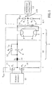
- Fig. 1 schematically an embodiment of the present invention is shown.
- the ballast according to the invention has an inverter 1 with two series-connected, connected to a DC voltage source U bus and alternately clocked transistor switches 17 and 18 ( T 1 and T 2 ) on.
- the switching can be effected by a control unit 23, which can be realized as an integrated circuit (IC) and in particular in an ASIC.
- a load circuit 3 is connected, which has a series resonant circuit 22 and the lamp 4.
- the series resonant circuit 22 consists of a resonance inductor 16 ( L R ) and a resonant capacitor 5 ( C R ).
- the discharge path of the gas discharge lamp 4 between the two heating coils 8 and 9 is, as known, connected in parallel with the resonance capacitor 5 (C R ) .
- a high-resistance resistor 12 ( R K ) is connected, so that bypassing the coupling capacitor 2 ( C K ) a low DC current I Dc through the upper heating coil 8 and a voltage divider explained later in detail. 7 can flow.
- a measurement signal 10b is generated (Sensor signal S2) tapped, which after an analog-to-digital conversion of a (digital) evaluation circuit 13 can be supplied.
- This evaluation circuit 13 can also be implemented as an integrated circuit.
- the voltage divider 7 together with the signal tap 11 thus represents a sensor circuit 6 for detecting a lamp failure as well as for detecting the lamp voltage.
- the evaluation circuit 13 can detect the following luminous states depending on the value of the sensor signal 10b (S2):
- the high-resistance resistor 12 (R K ) in the parallel branch of the coupling capacitor 2 (C K ) further has the advantage that it so-called "Walmen", ie alternately bright and dark sections in the gas discharge lamp 4, by providing a can at least greatly reduce certain DC component.
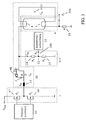
- Fig. 2 shows a further embodiment of the present invention.
- the coupling of the heating power takes place in the heating coils 8 and 9 inductively via the two coils 19 and 20 ( L h 1 and L h 2 ) of a transformer. While a capacitive coupling of the heating power is usually preferred for non-dimmed devices, the dimmed devices, the inductive form of Schumacherseinkopplung is preferred.
- the primary winding 21 ( L h 3 ) of a separate transformer can be used as a primary winding for the inductive heating power transmission.
- the resonance inductance 16 ( L R ) is also shown schematically that the primary winding 21 ( L h 3 ) of a separate transformer can be used as a primary winding for the inductive heating power transmission.
- the resonance inductance 16 ( L R ) is also shown schematically as a primary winding for the inductive coupling of the heating power into the heating coils 8 and 9 of the gas discharge lamp 4.
- any type of coupling of the heating power in the heating coils 8 and 9 can be applied.
- Inductance L h2 (implemented as a primary winding of a heating transformer Tr 2 ) for inductive coupling of the heating power in the second (lower) heating coil 9 of the gas discharge lamp.
- Inductance L h3 (realized as a primary winding of a heating transformer Tr 3 ) for inductive coupling of the heating power in the heating coils of the gas discharge lamp.
- 4 22 Series resonant circuit as part of the load circuit 3
- Control unit (implemented as IC or ASIC) for driving the two realized as a self-locking n-channel MOSFETs T 1 and T 2 transistor switch 17 and 18th 24 Coupling capacitor C h 1 in Einkoppelzweig the first (upper) heating coil 8 of the gas discharge lamp.
- 4 25 Coupling capacitor C h2 in Einkoppelzweig the second (lower) heating coil 9 of the gas discharge lamp.
- 4 26 Measuring resistor R , connected in series with the second (lower) heating coil of the gas discharge lamp.
Landscapes
- Circuit Arrangements For Discharge Lamps (AREA)
Claims (10)
- Ballast pour faire fonctionner une lampe à décharge de gaz avec des filaments de chauffage (8, 9), comportant:- un onduleur (1), qui comprend deux commutateurs (17, 18) connectés en série, raccordés à une source de tension continue (Ubus) et connectés en push-pull, et qui est relié au moyen d'un condensateur de couplage (2) à un circuit de charge (3), lequel comporte la lampe à décharge de gaz (4) présentant un filament de chauffage (8) faisant passer la tension et un circuit de résonnance série (22),caractérisé en ce que le ballast comporte en outre:- un circuit capteur (6), lequel est relié au filament de chauffage (8) de la lampe à décharge de gaz (4) faisant passer la tension et détecte un signal de mesure unique et- un circuit d'évaluation (13) destiné à l'identification combinée d'un dysfonctionnement de lampe, en particulier d'une cassure du filament de chauffage (8) faisant passer la tension, ainsi que de la tension de lampe appliquée à la lampe à décharge de gaz (4) à partir du signal de mesure unique (10b),dans lequel une résistance (12) à haute résistance est reliée en parallèle avec le condensateur de couplage (2) ainsi qu'avec le filament de chauffage (8) faisant passer la tension, dans lequel, si une lampe à décharge de gaz (4) sans dysfonctionnement est mise en place, un courant continu (IDC) circule à travers le filament de chauffage (8) faisant passer la tension par l'intermédiaire de la résistance (12) à haute résistance.
- Ballast selon la revendication 1,
dans lequel le circuit d'évaluation (13) détecte, à partir du courant continu (IDC) ne circulant pas, qu'aucune lampe à décharge de gaz (4) n'est mise en place ou que le filament de chauffage (8) faisant passer la tension est cassé. - Ballast électronique selon l'une des revendications précédentes,
caractérisé en ce que
le circuit capteur (6) est intégré dans un ASIC. - Ballast électronique selon l'une des revendications 1 à 3,
caractérisé en ce que
la puissance de chauffage est couplée de manière inductive par l'intermédiaire de deux bobines (19, 20) dans les filaments (8, 9) de la lampe à décharge de gaz (4). - Ballast selon la revendication 4,
caractérisé en ce que
une inductance (16) du circuit de résonnance série sert d'enroulement primaire pour le couplage inductif de la puissance de chauffage dans les filaments (8, 9) de la lampe (4). - Ballast électronique selon l'une des revendications précédentes,
caractérisé en ce que
le circuit d'évaluation (13) est agencé pour mettre au moins l'onduleur (1) hors circuit en cas de courant continu (IDC) ne circulant pas. - Procédé destiné à détecter la tension de lampe et à identifier un dysfonctionnement de lampe dans un ballast pour lampes à décharge de gaz (4) selon la revendication 1, présentant les étapes:- détecter le signal de mesure unique (10b),- déterminer une tension de lampe et identifier une cassure du filament de chauffage (8) de la lampe à décharge de gaz (4) faisant passer la tension à partir du signal de mesure unique (10b),dans lequel, si une lampe à décharge de gaz (4) sans dysfonctionnement est mise en place, un courant continu (IDC) circule à travers le filament de chauffage (8) faisant passer la tension par l'intermédiaire d'une résistance (12) à haute résistance en parallèle d'un condensateur de couplage (2).
- Procédé selon la revendication 7,
dans lequel il est détecté, à partir du courant continu (IDC) ne circulant pas, qu'aucune lampe à décharge de gaz (4) n'est mise en place ou que le filament de chauffage (8) faisant passer la tension est cassé. - Procédé selon l'une des revendications précédentes 7 à 8,
dans lequel en cas de détection du courant continu (IDC) ne circulant pas, au moins l'onduleur (1) est mis hors circuit. - Procédé selon l'une des revendications précédentes 7 à 9,
dans lequel le courant de filament est contrôlé pendant une phase de préchauffage ou d'allumage et le courant continu (IDC) est contrôlé pendant le fonctionnement normal.
Applications Claiming Priority (2)
| Application Number | Priority Date | Filing Date | Title |
|---|---|---|---|
| DE10206731.7A DE10206731B4 (de) | 2002-02-18 | 2002-02-18 | Lampensensor für ein Vorschaltgerät zum Betrieb einer Gasentladunslampe |
| EP03704522A EP1477046B1 (fr) | 2002-02-18 | 2003-02-03 | Capteur de lampe pour ballast concu pour faire fonctionner une lampe a decharge gazeuse |
Related Parent Applications (2)
| Application Number | Title | Priority Date | Filing Date |
|---|---|---|---|
| EP03704522.6 Division | 2003-02-03 | ||
| EP03704522A Division EP1477046B1 (fr) | 2002-02-18 | 2003-02-03 | Capteur de lampe pour ballast concu pour faire fonctionner une lampe a decharge gazeuse |
Publications (2)
| Publication Number | Publication Date |
|---|---|
| EP1945008A1 EP1945008A1 (fr) | 2008-07-16 |
| EP1945008B1 true EP1945008B1 (fr) | 2013-09-11 |
Family
ID=27635102
Family Applications (2)
| Application Number | Title | Priority Date | Filing Date |
|---|---|---|---|
| EP08155561.7A Expired - Lifetime EP1945008B1 (fr) | 2002-02-18 | 2003-02-03 | Capteur de lampes pour un appareil de montage destiné au fonctionnement d'une lampe à décharge |
| EP03704522A Expired - Lifetime EP1477046B1 (fr) | 2002-02-18 | 2003-02-03 | Capteur de lampe pour ballast concu pour faire fonctionner une lampe a decharge gazeuse |
Family Applications After (1)
| Application Number | Title | Priority Date | Filing Date |
|---|---|---|---|
| EP03704522A Expired - Lifetime EP1477046B1 (fr) | 2002-02-18 | 2003-02-03 | Capteur de lampe pour ballast concu pour faire fonctionner une lampe a decharge gazeuse |
Country Status (6)
| Country | Link |
|---|---|
| EP (2) | EP1945008B1 (fr) |
| CN (1) | CN1633830B (fr) |
| AT (1) | ATE464774T1 (fr) |
| AU (1) | AU2003206824A1 (fr) |
| DE (2) | DE10206731B4 (fr) |
| WO (1) | WO2003069963A1 (fr) |
Families Citing this family (5)
| Publication number | Priority date | Publication date | Assignee | Title |
|---|---|---|---|---|
| DE102004037390B4 (de) | 2004-08-02 | 2008-10-23 | Infineon Technologies Ag | Ansteuerschaltung für eine Leuchtstofflampe mit einer Diagnoseschaltung und Verfahren zur Diagnose einer Leuchtstofflampe |
| DE102005018763A1 (de) * | 2005-04-22 | 2006-10-26 | Tridonicatco Gmbh & Co. Kg | Betriebsgeräte mit Auswertung der Lampentemperatur bei der Lampenregelung |
| CN101155457B (zh) * | 2006-09-29 | 2011-06-08 | 鸿富锦精密工业(深圳)有限公司 | 具有跳火保护功能的光源驱动装置 |
| KR20110083823A (ko) * | 2010-01-15 | 2011-07-21 | 삼성전자주식회사 | 아크노이즈 검출 회로, 이를 포함하는 광원 구동 장치 및 이를 이용하는 광원 구동 방법 |
| CN106896244B (zh) * | 2017-04-12 | 2023-10-10 | 江苏伊施德创新科技有限公司 | 老炼夹具及采用该夹具做接触状况和老炼结果测试的方法 |
Family Cites Families (17)
| Publication number | Priority date | Publication date | Assignee | Title |
|---|---|---|---|---|
| US5041763A (en) * | 1989-12-22 | 1991-08-20 | Lutron Electronics Co., Inc. | Circuit and method for improved dimming of gas discharge lamps |
| DE4039161C2 (de) * | 1990-12-07 | 2001-05-31 | Zumtobel Ag Dornbirn | System zur Steuerung der Helligkeit und des Betriebsverhaltens von Leuchtstofflampen |
| DE4120649A1 (de) * | 1991-06-22 | 1992-12-24 | Vossloh Schwabe Gmbh | Ueberspannungsgeschuetztes vorschaltgeraet |
| EP0594880B1 (fr) * | 1992-10-28 | 1998-01-28 | Knobel Ag Lichttechnische Komponenten | Procédé et circuit d'amorçage de lampes fluorescentes lorsque les électrodes de préchauffage ont atteint une température donnée |
| DE4301276A1 (de) * | 1993-01-19 | 1994-07-21 | Patent Treuhand Ges Fuer Elektrische Gluehlampen Mbh | Verfahren und Stromversorgungseinheit zum stabilisierten Betrieb einer Natrium-Hochdruckentladungslampe |
| DE4436463A1 (de) * | 1994-10-12 | 1996-04-18 | Patent Treuhand Ges Fuer Elektrische Gluehlampen Mbh | Schaltungsanordnung zum Betrieb einer oder mehrerer Niederdruckentladungslampen |
| DE19530485A1 (de) * | 1995-08-18 | 1997-02-20 | Patent Treuhand Ges Fuer Elektrische Gluehlampen Mbh | Verfahren und Schaltungsanordnung zum Betreiben einer elektrischen Lampe |
| DE19613149A1 (de) * | 1996-04-03 | 1997-10-09 | Patent Treuhand Ges Fuer Elektrische Gluehlampen Mbh | Schaltungsanordnung zum Betrieb elektrischer Lampen |
| US5808422A (en) * | 1996-05-10 | 1998-09-15 | Philips Electronics North America | Lamp ballast with lamp rectification detection circuitry |
| CN1172412A (zh) * | 1996-07-25 | 1998-02-04 | 浙江长丰电器实业公司 | 用于气体放电灯的电子镇流器 |
| JP3858317B2 (ja) * | 1996-11-29 | 2006-12-13 | 東芝ライテック株式会社 | 放電灯点灯装置及び照明装置 |
| US5883473A (en) * | 1997-12-03 | 1999-03-16 | Motorola Inc. | Electronic Ballast with inverter protection circuit |
| ES2195438T3 (es) * | 1997-12-23 | 2003-12-01 | Tridonicatco Gmbh & Co Kg | Balasto electronico. |
| DE19916080C2 (de) * | 1999-04-09 | 2001-11-22 | Vossloh Schwabe Elektronik | Vorschaltgerät mit Fehlererkennung |
| DE19923945A1 (de) * | 1999-05-25 | 2000-12-28 | Tridonic Bauelemente | Elektronisches Vorschaltgerät für mindestens eine Niederdruck-Entladungslampe |
| DE19934687A1 (de) * | 1999-05-25 | 2000-12-21 | Tridonic Bauelemente | Elektronisches Vorschaltgerät für mindestens eine Niederdruck-Entladungslampe |
| CN2421799Y (zh) * | 2000-04-27 | 2001-02-28 | 上海市照明灯具研究所 | 高品质可调光电子镇流器 |
-
2002
- 2002-02-18 DE DE10206731.7A patent/DE10206731B4/de not_active Expired - Fee Related
-
2003
- 2003-02-03 CN CN03804114.6A patent/CN1633830B/zh not_active Expired - Fee Related
- 2003-02-03 AT AT03704522T patent/ATE464774T1/de active
- 2003-02-03 EP EP08155561.7A patent/EP1945008B1/fr not_active Expired - Lifetime
- 2003-02-03 EP EP03704522A patent/EP1477046B1/fr not_active Expired - Lifetime
- 2003-02-03 AU AU2003206824A patent/AU2003206824A1/en not_active Abandoned
- 2003-02-03 DE DE50312613T patent/DE50312613D1/de not_active Expired - Lifetime
- 2003-02-03 WO PCT/EP2003/001046 patent/WO2003069963A1/fr not_active Ceased
Also Published As
| Publication number | Publication date |
|---|---|
| CN1633830A (zh) | 2005-06-29 |
| WO2003069963A1 (fr) | 2003-08-21 |
| EP1477046B1 (fr) | 2010-04-14 |
| ATE464774T1 (de) | 2010-04-15 |
| DE10206731A1 (de) | 2003-08-28 |
| AU2003206824A1 (en) | 2003-09-04 |
| DE50312613D1 (de) | 2010-05-27 |
| DE10206731B4 (de) | 2016-12-22 |
| EP1477046A1 (fr) | 2004-11-17 |
| EP1945008A1 (fr) | 2008-07-16 |
| CN1633830B (zh) | 2010-06-30 |
Similar Documents
| Publication | Publication Date | Title |
|---|---|---|
| EP1103165B1 (fr) | Ballast electronique destine a au moins une lampe a decharge basse tension | |
| EP0677981B1 (fr) | Ballast, avec dispositif de reconnaissance de changement de lampe, pour tubes à décharge | |
| EP1103166B1 (fr) | Ballast electronique destine a au moins une lampe a decharge basse tension | |
| EP2377372B1 (fr) | Méthode, appareil et système d'éclairage | |
| DE102004037388B4 (de) | Verfahren zur Detektion eines Nicht-Nullspannungsschaltbetriebs eines Vorschaltgeräts für Leuchtstofflampen und Vorschaltgerät | |
| EP1872630B1 (fr) | Chauffage intelligent par convertisseur a transfert indirect | |
| EP1425943B1 (fr) | Procede et dispositif destines au fonctionnement economique d'un tube fluorescent | |
| EP1945008B1 (fr) | Capteur de lampes pour un appareil de montage destiné au fonctionnement d'une lampe à décharge | |
| EP0871347A1 (fr) | Ballast à réamorçage automatique | |
| EP2274960B1 (fr) | Procédé et agencement de circuits pour faire fonctionner au moins une lampe à décharge | |
| EP2380408B1 (fr) | Circuit de détection et procédé pour commander un tube fluorescent | |
| WO2008122324A1 (fr) | Circuit pour le chauffage d'un filament | |
| EP1280388B1 (fr) | Ballast électronique avec un mode de préchauffage | |
| EP2380409B1 (fr) | Circuit de détection et procédé d'excitation d'une lampe fluorescente | |
| DE102007011646B4 (de) | Extern konfigurierbar integrierbare Steuerschaltung für Betriebsgeräte für Leuchtmittel | |
| DE102010029511B4 (de) | Schaltungsanordnung zum Betreiben einer Entladungslampe | |
| DE10127135B4 (de) | Dimmbares elektronisches Vorschaltgerät | |
| DE102012204118A1 (de) | Betrieb von Leuchtmitteln | |
| DE102007027179A1 (de) | Steuerschaltung für Leuchtmittel-Betriebsgeräte | |
| DE10204432A1 (de) | Elektronisches Vorschaltgerät mit Wendelheizung | |
| EP2529599A2 (fr) | Appareil pour faire fonctionner des lampes à décharge de gaz | |
| EP2015618A2 (fr) | Circuit destiné à faire fonctionner une lampe fluorescente |
Legal Events
| Date | Code | Title | Description |
|---|---|---|---|
| PUAI | Public reference made under article 153(3) epc to a published international application that has entered the european phase |
Free format text: ORIGINAL CODE: 0009012 |
|
| AC | Divisional application: reference to earlier application |
Ref document number: 1477046 Country of ref document: EP Kind code of ref document: P |
|
| AK | Designated contracting states |
Kind code of ref document: A1 Designated state(s): AT BE BG CH CY CZ DE DK EE ES FI FR GB GR HU IE IT LI LU MC NL PT SE SI SK TR |
|
| 17P | Request for examination filed |
Effective date: 20081119 |
|
| 17Q | First examination report despatched |
Effective date: 20090108 |
|
| AKX | Designation fees paid |
Designated state(s): AT BE BG CH CY CZ DE DK EE ES FI FR GB GR HU IE IT LI LU MC NL PT SE SI SK TR |
|
| RAP1 | Party data changed (applicant data changed or rights of an application transferred) |
Owner name: TRIDONIC GMBH & CO KG |
|
| GRAP | Despatch of communication of intention to grant a patent |
Free format text: ORIGINAL CODE: EPIDOSNIGR1 |
|
| RIC1 | Information provided on ipc code assigned before grant |
Ipc: H05B 41/298 20060101AFI20130228BHEP Ipc: H05B 41/285 20060101ALI20130228BHEP |
|
| GRAS | Grant fee paid |
Free format text: ORIGINAL CODE: EPIDOSNIGR3 |
|
| GRAA | (expected) grant |
Free format text: ORIGINAL CODE: 0009210 |
|
| AC | Divisional application: reference to earlier application |
Ref document number: 1477046 Country of ref document: EP Kind code of ref document: P |
|
| AK | Designated contracting states |
Kind code of ref document: B1 Designated state(s): AT BE BG CH CY CZ DE DK EE ES FI FR GB GR HU IE IT LI LU MC NL PT SE SI SK TR |
|
| REG | Reference to a national code |
Ref country code: GB Ref legal event code: FG4D Free format text: NOT ENGLISH |
|
| REG | Reference to a national code |
Ref country code: CH Ref legal event code: EP |
|
| REG | Reference to a national code |
Ref country code: AT Ref legal event code: REF Ref document number: 632224 Country of ref document: AT Kind code of ref document: T Effective date: 20130915 |
|
| REG | Reference to a national code |
Ref country code: IE Ref legal event code: FG4D Free format text: LANGUAGE OF EP DOCUMENT: GERMAN |
|
| REG | Reference to a national code |
Ref country code: DE Ref legal event code: R096 Ref document number: 50314894 Country of ref document: DE Effective date: 20131107 |
|
| PG25 | Lapsed in a contracting state [announced via postgrant information from national office to epo] |
Ref country code: SE Free format text: LAPSE BECAUSE OF FAILURE TO SUBMIT A TRANSLATION OF THE DESCRIPTION OR TO PAY THE FEE WITHIN THE PRESCRIBED TIME-LIMIT Effective date: 20130911 Ref country code: CY Free format text: LAPSE BECAUSE OF FAILURE TO SUBMIT A TRANSLATION OF THE DESCRIPTION OR TO PAY THE FEE WITHIN THE PRESCRIBED TIME-LIMIT Effective date: 20130626 |
|
| REG | Reference to a national code |
Ref country code: NL Ref legal event code: VDEP Effective date: 20130911 |
|
| PG25 | Lapsed in a contracting state [announced via postgrant information from national office to epo] |
Ref country code: SI Free format text: LAPSE BECAUSE OF FAILURE TO SUBMIT A TRANSLATION OF THE DESCRIPTION OR TO PAY THE FEE WITHIN THE PRESCRIBED TIME-LIMIT Effective date: 20130911 Ref country code: FI Free format text: LAPSE BECAUSE OF FAILURE TO SUBMIT A TRANSLATION OF THE DESCRIPTION OR TO PAY THE FEE WITHIN THE PRESCRIBED TIME-LIMIT Effective date: 20130911 Ref country code: GR Free format text: LAPSE BECAUSE OF FAILURE TO SUBMIT A TRANSLATION OF THE DESCRIPTION OR TO PAY THE FEE WITHIN THE PRESCRIBED TIME-LIMIT Effective date: 20131212 |
|
| PG25 | Lapsed in a contracting state [announced via postgrant information from national office to epo] |
Ref country code: CY Free format text: LAPSE BECAUSE OF FAILURE TO SUBMIT A TRANSLATION OF THE DESCRIPTION OR TO PAY THE FEE WITHIN THE PRESCRIBED TIME-LIMIT Effective date: 20130911 |
|
| PG25 | Lapsed in a contracting state [announced via postgrant information from national office to epo] |
Ref country code: EE Free format text: LAPSE BECAUSE OF FAILURE TO SUBMIT A TRANSLATION OF THE DESCRIPTION OR TO PAY THE FEE WITHIN THE PRESCRIBED TIME-LIMIT Effective date: 20130911 Ref country code: SK Free format text: LAPSE BECAUSE OF FAILURE TO SUBMIT A TRANSLATION OF THE DESCRIPTION OR TO PAY THE FEE WITHIN THE PRESCRIBED TIME-LIMIT Effective date: 20130911 Ref country code: NL Free format text: LAPSE BECAUSE OF FAILURE TO SUBMIT A TRANSLATION OF THE DESCRIPTION OR TO PAY THE FEE WITHIN THE PRESCRIBED TIME-LIMIT Effective date: 20130911 Ref country code: CZ Free format text: LAPSE BECAUSE OF FAILURE TO SUBMIT A TRANSLATION OF THE DESCRIPTION OR TO PAY THE FEE WITHIN THE PRESCRIBED TIME-LIMIT Effective date: 20130911 |
|
| PG25 | Lapsed in a contracting state [announced via postgrant information from national office to epo] |
Ref country code: ES Free format text: LAPSE BECAUSE OF FAILURE TO SUBMIT A TRANSLATION OF THE DESCRIPTION OR TO PAY THE FEE WITHIN THE PRESCRIBED TIME-LIMIT Effective date: 20130911 |
|
| REG | Reference to a national code |
Ref country code: DE Ref legal event code: R097 Ref document number: 50314894 Country of ref document: DE |
|
| PG25 | Lapsed in a contracting state [announced via postgrant information from national office to epo] |
Ref country code: PT Free format text: LAPSE BECAUSE OF FAILURE TO SUBMIT A TRANSLATION OF THE DESCRIPTION OR TO PAY THE FEE WITHIN THE PRESCRIBED TIME-LIMIT Effective date: 20140113 |
|
| PLBE | No opposition filed within time limit |
Free format text: ORIGINAL CODE: 0009261 |
|
| STAA | Information on the status of an ep patent application or granted ep patent |
Free format text: STATUS: NO OPPOSITION FILED WITHIN TIME LIMIT |
|
| 26N | No opposition filed |
Effective date: 20140612 |
|
| PG25 | Lapsed in a contracting state [announced via postgrant information from national office to epo] |
Ref country code: IT Free format text: LAPSE BECAUSE OF FAILURE TO SUBMIT A TRANSLATION OF THE DESCRIPTION OR TO PAY THE FEE WITHIN THE PRESCRIBED TIME-LIMIT Effective date: 20130911 |
|
| BERE | Be: lapsed |
Owner name: TRIDONIC GMBH & CO KG Effective date: 20140228 |
|
| REG | Reference to a national code |
Ref country code: DE Ref legal event code: R097 Ref document number: 50314894 Country of ref document: DE Effective date: 20140612 |
|
| PG25 | Lapsed in a contracting state [announced via postgrant information from national office to epo] |
Ref country code: LU Free format text: LAPSE BECAUSE OF FAILURE TO SUBMIT A TRANSLATION OF THE DESCRIPTION OR TO PAY THE FEE WITHIN THE PRESCRIBED TIME-LIMIT Effective date: 20140203 Ref country code: DK Free format text: LAPSE BECAUSE OF FAILURE TO SUBMIT A TRANSLATION OF THE DESCRIPTION OR TO PAY THE FEE WITHIN THE PRESCRIBED TIME-LIMIT Effective date: 20130911 Ref country code: MC Free format text: LAPSE BECAUSE OF FAILURE TO SUBMIT A TRANSLATION OF THE DESCRIPTION OR TO PAY THE FEE WITHIN THE PRESCRIBED TIME-LIMIT Effective date: 20130911 |
|
| REG | Reference to a national code |
Ref country code: CH Ref legal event code: PL |
|
| PG25 | Lapsed in a contracting state [announced via postgrant information from national office to epo] |
Ref country code: CH Free format text: LAPSE BECAUSE OF NON-PAYMENT OF DUE FEES Effective date: 20140228 Ref country code: LI Free format text: LAPSE BECAUSE OF NON-PAYMENT OF DUE FEES Effective date: 20140228 |
|
| REG | Reference to a national code |
Ref country code: IE Ref legal event code: MM4A |
|
| PG25 | Lapsed in a contracting state [announced via postgrant information from national office to epo] |
Ref country code: BE Free format text: LAPSE BECAUSE OF NON-PAYMENT OF DUE FEES Effective date: 20140228 Ref country code: IE Free format text: LAPSE BECAUSE OF NON-PAYMENT OF DUE FEES Effective date: 20140203 |
|
| REG | Reference to a national code |
Ref country code: AT Ref legal event code: MM01 Ref document number: 632224 Country of ref document: AT Kind code of ref document: T Effective date: 20140203 |
|
| PG25 | Lapsed in a contracting state [announced via postgrant information from national office to epo] |
Ref country code: AT Free format text: LAPSE BECAUSE OF NON-PAYMENT OF DUE FEES Effective date: 20140203 |
|
| REG | Reference to a national code |
Ref country code: FR Ref legal event code: PLFP Year of fee payment: 14 |
|
| PG25 | Lapsed in a contracting state [announced via postgrant information from national office to epo] |
Ref country code: BG Free format text: LAPSE BECAUSE OF FAILURE TO SUBMIT A TRANSLATION OF THE DESCRIPTION OR TO PAY THE FEE WITHIN THE PRESCRIBED TIME-LIMIT Effective date: 20130911 |
|
| PGFP | Annual fee paid to national office [announced via postgrant information from national office to epo] |
Ref country code: FR Payment date: 20160229 Year of fee payment: 14 Ref country code: GB Payment date: 20160226 Year of fee payment: 14 |
|
| PG25 | Lapsed in a contracting state [announced via postgrant information from national office to epo] |
Ref country code: TR Free format text: LAPSE BECAUSE OF FAILURE TO SUBMIT A TRANSLATION OF THE DESCRIPTION OR TO PAY THE FEE WITHIN THE PRESCRIBED TIME-LIMIT Effective date: 20130911 Ref country code: HU Free format text: LAPSE BECAUSE OF FAILURE TO SUBMIT A TRANSLATION OF THE DESCRIPTION OR TO PAY THE FEE WITHIN THE PRESCRIBED TIME-LIMIT; INVALID AB INITIO Effective date: 20030203 |
|
| PGFP | Annual fee paid to national office [announced via postgrant information from national office to epo] |
Ref country code: DE Payment date: 20160502 Year of fee payment: 14 |
|
| REG | Reference to a national code |
Ref country code: DE Ref legal event code: R119 Ref document number: 50314894 Country of ref document: DE |
|
| GBPC | Gb: european patent ceased through non-payment of renewal fee |
Effective date: 20170203 |
|
| REG | Reference to a national code |
Ref country code: FR Ref legal event code: ST Effective date: 20171031 |
|
| PG25 | Lapsed in a contracting state [announced via postgrant information from national office to epo] |
Ref country code: DE Free format text: LAPSE BECAUSE OF NON-PAYMENT OF DUE FEES Effective date: 20170901 Ref country code: FR Free format text: LAPSE BECAUSE OF NON-PAYMENT OF DUE FEES Effective date: 20170228 |
|
| PG25 | Lapsed in a contracting state [announced via postgrant information from national office to epo] |
Ref country code: GB Free format text: LAPSE BECAUSE OF NON-PAYMENT OF DUE FEES Effective date: 20170203 |