EP1946025B1 - Dämpfer und heimbartürvorrichtung für diese(n) verwendenden kühlschrank - Google Patents
Dämpfer und heimbartürvorrichtung für diese(n) verwendenden kühlschrank Download PDFInfo
- Publication number
- EP1946025B1 EP1946025B1 EP06798841.0A EP06798841A EP1946025B1 EP 1946025 B1 EP1946025 B1 EP 1946025B1 EP 06798841 A EP06798841 A EP 06798841A EP 1946025 B1 EP1946025 B1 EP 1946025B1
- Authority
- EP
- European Patent Office
- Prior art keywords
- home
- damper
- bar door
- bar
- guide plate
- Prior art date
- Legal status (The legal status is an assumption and is not a legal conclusion. Google has not performed a legal analysis and makes no representation as to the accuracy of the status listed.)
- Not-in-force
Links
Images


Classifications
-
- F—MECHANICAL ENGINEERING; LIGHTING; HEATING; WEAPONS; BLASTING
- F25—REFRIGERATION OR COOLING; COMBINED HEATING AND REFRIGERATION SYSTEMS; HEAT PUMP SYSTEMS; MANUFACTURE OR STORAGE OF ICE; LIQUEFACTION SOLIDIFICATION OF GASES
- F25D—REFRIGERATORS; COLD ROOMS; ICE-BOXES; COOLING OR FREEZING APPARATUS NOT OTHERWISE PROVIDED FOR
- F25D23/00—General constructional features
- F25D23/02—Doors; Covers
-
- F—MECHANICAL ENGINEERING; LIGHTING; HEATING; WEAPONS; BLASTING
- F16—ENGINEERING ELEMENTS AND UNITS; GENERAL MEASURES FOR PRODUCING AND MAINTAINING EFFECTIVE FUNCTIONING OF MACHINES OR INSTALLATIONS; THERMAL INSULATION IN GENERAL
- F16F—SPRINGS; SHOCK-ABSORBERS; MEANS FOR DAMPING VIBRATION
- F16F9/00—Springs, vibration-dampers, shock-absorbers, or similarly-constructed movement-dampers using a fluid or the equivalent as damping medium
- F16F9/10—Springs, vibration-dampers, shock-absorbers, or similarly-constructed movement-dampers using a fluid or the equivalent as damping medium using liquid only; using a fluid of which the nature is immaterial
- F16F9/12—Devices with one or more rotary vanes turning in the fluid any throttling effect being immaterial, i.e. damping by viscous shear effect only
-
- E—FIXED CONSTRUCTIONS
- E05—LOCKS; KEYS; WINDOW OR DOOR FITTINGS; SAFES
- E05D—HINGES OR SUSPENSION DEVICES FOR DOORS, WINDOWS OR WINGS
- E05D7/00—Hinges or pivots of special construction
- E05D7/08—Hinges or pivots of special construction for use in suspensions comprising two spigots placed at opposite edges of the wing, especially at the top and the bottom, e.g. trunnions
- E05D7/081—Hinges or pivots of special construction for use in suspensions comprising two spigots placed at opposite edges of the wing, especially at the top and the bottom, e.g. trunnions the pivot axis of the wing being situated near one edge of the wing, especially at the top and bottom, e.g. trunnions
-
- E—FIXED CONSTRUCTIONS
- E05—LOCKS; KEYS; WINDOW OR DOOR FITTINGS; SAFES
- E05F—DEVICES FOR MOVING WINGS INTO OPEN OR CLOSED POSITION; CHECKS FOR WINGS; WING FITTINGS NOT OTHERWISE PROVIDED FOR, CONCERNED WITH THE FUNCTIONING OF THE WING
- E05F3/00—Closers or openers with braking devices, e.g. checks; Construction of pneumatic or liquid braking devices
- E05F3/14—Closers or openers with braking devices, e.g. checks; Construction of pneumatic or liquid braking devices with fluid brakes of the rotary type
-
- E—FIXED CONSTRUCTIONS
- E05—LOCKS; KEYS; WINDOW OR DOOR FITTINGS; SAFES
- E05F—DEVICES FOR MOVING WINGS INTO OPEN OR CLOSED POSITION; CHECKS FOR WINGS; WING FITTINGS NOT OTHERWISE PROVIDED FOR, CONCERNED WITH THE FUNCTIONING OF THE WING
- E05F3/00—Closers or openers with braking devices, e.g. checks; Construction of pneumatic or liquid braking devices
- E05F3/20—Closers or openers with braking devices, e.g. checks; Construction of pneumatic or liquid braking devices in hinges
-
- E—FIXED CONSTRUCTIONS
- E05—LOCKS; KEYS; WINDOW OR DOOR FITTINGS; SAFES
- E05Y—INDEXING SCHEME ASSOCIATED WITH SUBCLASSES E05D AND E05F, RELATING TO CONSTRUCTION ELEMENTS, ELECTRIC CONTROL, POWER SUPPLY, POWER SIGNAL OR TRANSMISSION, USER INTERFACES, MOUNTING OR COUPLING, DETAILS, ACCESSORIES, AUXILIARY OPERATIONS NOT OTHERWISE PROVIDED FOR, APPLICATION THEREOF
- E05Y2201/00—Constructional elements; Accessories therefor
- E05Y2201/20—Brakes; Disengaging means; Holders; Stops; Valves; Accessories therefor
- E05Y2201/21—Brakes
-
- E—FIXED CONSTRUCTIONS
- E05—LOCKS; KEYS; WINDOW OR DOOR FITTINGS; SAFES
- E05Y—INDEXING SCHEME ASSOCIATED WITH SUBCLASSES E05D AND E05F, RELATING TO CONSTRUCTION ELEMENTS, ELECTRIC CONTROL, POWER SUPPLY, POWER SIGNAL OR TRANSMISSION, USER INTERFACES, MOUNTING OR COUPLING, DETAILS, ACCESSORIES, AUXILIARY OPERATIONS NOT OTHERWISE PROVIDED FOR, APPLICATION THEREOF
- E05Y2201/00—Constructional elements; Accessories therefor
- E05Y2201/20—Brakes; Disengaging means; Holders; Stops; Valves; Accessories therefor
- E05Y2201/252—Type of friction
- E05Y2201/254—Fluid or viscous friction
-
- E—FIXED CONSTRUCTIONS
- E05—LOCKS; KEYS; WINDOW OR DOOR FITTINGS; SAFES
- E05Y—INDEXING SCHEME ASSOCIATED WITH SUBCLASSES E05D AND E05F, RELATING TO CONSTRUCTION ELEMENTS, ELECTRIC CONTROL, POWER SUPPLY, POWER SIGNAL OR TRANSMISSION, USER INTERFACES, MOUNTING OR COUPLING, DETAILS, ACCESSORIES, AUXILIARY OPERATIONS NOT OTHERWISE PROVIDED FOR, APPLICATION THEREOF
- E05Y2201/00—Constructional elements; Accessories therefor
- E05Y2201/20—Brakes; Disengaging means; Holders; Stops; Valves; Accessories therefor
- E05Y2201/262—Type of motion, e.g. braking
- E05Y2201/266—Type of motion, e.g. braking rotary
-
- E—FIXED CONSTRUCTIONS
- E05—LOCKS; KEYS; WINDOW OR DOOR FITTINGS; SAFES
- E05Y—INDEXING SCHEME ASSOCIATED WITH SUBCLASSES E05D AND E05F, RELATING TO CONSTRUCTION ELEMENTS, ELECTRIC CONTROL, POWER SUPPLY, POWER SIGNAL OR TRANSMISSION, USER INTERFACES, MOUNTING OR COUPLING, DETAILS, ACCESSORIES, AUXILIARY OPERATIONS NOT OTHERWISE PROVIDED FOR, APPLICATION THEREOF
- E05Y2800/00—Details, accessories and auxiliary operations not otherwise provided for
- E05Y2800/71—Secondary wings, e.g. pass doors
-
- E—FIXED CONSTRUCTIONS
- E05—LOCKS; KEYS; WINDOW OR DOOR FITTINGS; SAFES
- E05Y—INDEXING SCHEME ASSOCIATED WITH SUBCLASSES E05D AND E05F, RELATING TO CONSTRUCTION ELEMENTS, ELECTRIC CONTROL, POWER SUPPLY, POWER SIGNAL OR TRANSMISSION, USER INTERFACES, MOUNTING OR COUPLING, DETAILS, ACCESSORIES, AUXILIARY OPERATIONS NOT OTHERWISE PROVIDED FOR, APPLICATION THEREOF
- E05Y2900/00—Application of doors, windows, wings or fittings thereof
- E05Y2900/30—Application of doors, windows, wings or fittings thereof for domestic appliances
- E05Y2900/31—Application of doors, windows, wings or fittings thereof for domestic appliances for refrigerators
-
- F—MECHANICAL ENGINEERING; LIGHTING; HEATING; WEAPONS; BLASTING
- F25—REFRIGERATION OR COOLING; COMBINED HEATING AND REFRIGERATION SYSTEMS; HEAT PUMP SYSTEMS; MANUFACTURE OR STORAGE OF ICE; LIQUEFACTION SOLIDIFICATION OF GASES
- F25D—REFRIGERATORS; COLD ROOMS; ICE-BOXES; COOLING OR FREEZING APPARATUS NOT OTHERWISE PROVIDED FOR
- F25D2323/00—General constructional features not provided for in other groups of this subclass
- F25D2323/02—Details of doors or covers not otherwise covered
- F25D2323/023—Door in door constructions
Definitions
- the present invention relates to a refrigerator, and more particularly, to a home-b ar door apparatus for opening or closing a home bar that allows beverages or the like in a storage space to be taken in or out without opening a door of a refrigerator, and a dam per for use in the home-bar door apparatus.
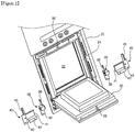
- Fig. 1 is a perspective view showing an appearance of a general refrigerator.
- a storage space (not shown) is formed in a body 1 of the refrigerator
- the storage space is divided into a left freezing chamber and a right refrigerating cha mber by a mullion (not shown) that is vertically placed to partition the interior of the bo dy 1 at the center thereof.
- the freezing chamber and the refrigerating chamber are opened or closed by doo rs 3 and 3', respectively.
- the doors 3 and 3' are pivotally supported by hinge assembli es 5 in upper and lower portions at both lateral ends of a front face of the body 1.
- Han dies 7 are also provided on the doors 3 and 3' to open or close the doors.
- a home bar 10 is provided in the door 3' for opening or closing the refrigerating chamber.
- the home bar 10 allows a stored article to be taken in or out without openin g the door 3'.
- a rectangular home-b ar frame 12 is installed in an opening formed through the door 3'.
- a stored article can be taken in or out through a central opening of the home-bar frame 12.
- the opening is opened or closed by a home-bar door 14.
- the home-bar door 14 is formed to hav e a shape capable of being placed in the opening.
- an insulation layer is form ed within the home-bar door 14.
- An upper end of the home-bar door 14 is rotated downward by approximately 90 degrees about rotational shafts (not shown) provided at both ends of a lower portion so as to open the opening.
- a damper (not shown) may also be used.
- the home-bar door apparatus of the convention refrigerator has the foll owing problems.
- the rotational shaft serving as the center of rotation of the home-bar door 14 generally protrudes from the damper, and the damper is installed inside the home-ba r door 14.
- the rotational shaft of the damper since the rotational shaft of the damper is installed in the home-bar fr ame 12 and thus entirely supports the load of the home-bar door 14, there is a problem i n that the coupled state thereof may be released due to long-term use or opening/closing impact of the home-bar door 14.
- the prior art has a problem in that when the home-bar door 14 is clos ed, initial opening of the home-bar door needs much force due to difference between ext ernal and internal pressure of the storage space and due to adhesion force between a gas ket positioned at the back of the home-bar door 14 and a gasket positioned at the home-bar frame 12.
- US2004178710 discloses a supplementary storage device for a refrigerator i ncluding an opening in a refrigerator door for making an inside of the refrigerator in co mmunication with an outside of the refrigerator to put food into an inside of the refriger ator directly, a supplementary door on the refrigerator door for opening or closing the op ening, and at least one damper for rotatably coupling the supplementary door to the refri gerator door, to damp a rotation force generated in opening or closing the supplementary door, thereby minimizing impact and noise.
- KR200307805 (Y1 ) discloses a housing having a hollow interior and an uneven surface formed at an inner lower portion thereof;
- An engaging block inserted into the ho llow of the housing and having a concave / convex surface formed on the lower surface t hereof so as to engage with the concave / convex surface, and a coupling hole formed on the concave / convex surface;
- a rotation bar provided at an upper side of the locking bl ock and inserted into a hollow of the housing, the rotation bar being fitted in a predeter mined engagement block so that an upper portion thereof is exposed to the outside and h aving a coupling hole formed at a lower portion thereof;
- a spring disposed between the rotation bar and the engagement block and having upper and lower ends inserted int o a lower portion of the rotation bar and a coupling hole formed on an upper portion of t he engagement block.
- An object of the present invention is to provide a more secure installation state of a damper for smoothing an opening/closing operation of a home-bar door.
- Another object of the present invention is to position stopping structures for regu lating the degree of opening of a home-bar door at both ends of the home-bar door.
- a further object of the present invention is to enhance durability and replaceabili ty of components of a home-bar door apparatus.
- a still further object of the present invention is to stably control an opening/closi ng speed of a home-bar door.
- a home-bar door apparatus for a refrigerator comprising a home-bar frame inst ailed to a door of the refrigerator and having an opening formed through a center thereof ; a home-bar door provided for selectively opening or closing the opening and having rotational shafts as a center of rotation protruding from both ends of a lower portion thereof; dampers installed to a rear face of the home-bar frame to control an opening/closing speed of the home-bar door, the rotational shafts of the home-bar door being inserted into and relatively rotated with respect to the dampers; and damper brackets mounted together with the dampers to the rear face of the home-bar frame, wherein the damper mount plates are formed to extend at both ends of each of the dampers so that extension surfaces of the damper mount plates are orthogonal to each other.
- the damper includes: a damper body having a seating space formed therein; a cover plate mounted to one side of the damper body to shield the seating space and having a fixing recess formed in an inner surface thereof; a rotating part installed inside the seating space and rotated together with the rotational shaft of the home-bar door; an elastic member for exhibiting an elastic force in an initial opening stage and a last opening stage of the rotating part; a fixed guide plate fixed to the cover plate, one end of the elastic member being fixed to the fixed guide plate; and a movable guide plate installed to face the fixed guide plate with the elastic member interposed therebetween, the other end of the elastic member being fixed to the movable guide plate to selectively move together with the rotating part, wherein a damping fluid is filled in the seating space.
- a close contact portion to be brought into contact with the rear face of the home-bar frame is provided in each of the damper brackets, and the close contact portion includes a first rear mount and a side mount that are fastened to the home-bar frame together with the damper mount plate.
- the damper bracket is further provided with a second rear mount mounted to the rear face of the home-bar frame.
- the rotating part includes a shaft connection boss having a shaft insert ion portion to which the rotational shaft of the home-bar door is coupled, the shaft insert ion portion passing through the fixed guide plate, the movable guide plate and the elasti c member.
- a cutout having first and second walls formed at both ends thereof by which a movable end of the elastic member is selectively caught is provided on a surfa ce of the rotating part where the shaft connection boss is formed, so that the rotating part and the movable guide plate are moved integrally in a selective manner.
- the shaft insertion portion formed in the shaft connection boss of the rotating part is exposed outward through a through-hole formed through a center of the c over plate.
- At least one of the rotational shafts of the home-bar door protrudes an d is supported by a spring in a direction in which the rotational shaft protrudes outside th e home-bar door.
- a damper comprising a damper body formed with a seating space in which a damping fluid is filled; a cover plate mounted to one side of the damper body to shield the seating space and having a fixing recess formed in an inner surface thereof; a rotatin g part rotatably installed inside the seating space and having a shaft connection boss exp osed outward through the cover plate; an elastic member for exhibiting an elastic force i n an opening direction in an initial opening stage and in a closing direction in a last open ing stage of the rotating part; a fixed guide plate fixed to the cover plate, one end of the elastic member being fixed to the fixed guide plate; and a movable guide plate installed to face the fixed guide plate with the elastic member interposed therebetween, the other end of the elastic member being fixed to the movable guide plate to selectively move tog ether with the rotating part.
- this invention further comprises damper mount plates provided on an outer surface of the damper body, wherein the damper mount plates extend from both e nds of the damper body in opposite directions so that extension surfaces thereof are orth ogonal to each other.
- a cutout having first and second walls formed at both ends thereof is provided on a surface of the rotating part where the shaft connection boss is formed, so t hat the other end of the elastic member can be selectively brought into contact with the f irst and second walls, whereby the rotating part and the movable guide plate are moved i ntegrally in a selective manner.
- the shaft connection boss of the rotating part passes through centers o f the fixed guide plate, the elastic member, the movable guide plate and the cover plate, and a shaft insertion portion is formed in the shaft connection boss.
- partition steps protrude from a bottom of the seating space of the da mper body, cam surfaces are formed between the partition steps, and partition steps are provided on a surface of the rotating part corresponding to the cam surfaces, thereby cau sing a damping action by the damping fluid.
- each of the fixed guide plate and the movable guide plate has a boss passing hole at a center thereof, lobes protrude around a periphery of the boss passing ho le, and a hole is formed through one of the lobes so that an end of the elastic member is caught in the hole.
- the elastic member comprises a torsion spring including a cylindrical body and fixed and movable ends provided at both ends of the cylindrical body to be cau ght in the holes of the fixed guide plate and the movable guide plate.
- an oil injection hole is formed in the damper body to communicate th e seating space with the outside, and a fastening member is fastened to the oil injection hole to clog the oil injection hole.
- the damper can be more securely installed at the home-bar frame, the stopping structures for regulating the degree of opening of the h ome-bar door are positioned at both ends of the home-bar door so as to more securely ke ep the center of rotation of the home-bar door, and an opening/closing speed of the hom e-bar door can be stably controlled.
- the damper used for the home-bar door of the present invention facili tates to open the home-bar door at an initial opening stage, and also prevents the home-b ar door from being abruptly opened at a last opening stage due to the weight of the home -bar door itself, thereby enhancing operational reliability of the home-bar door.
- a home-bar frame 20 is made in the form of a substanti ally rectangular frame.
- the home-bar frame 20 is installed to be partially exposed on a front face of a refrigerator door.
- a rectangular opening 22 is formed at the center of t he home-bar frame 20.
- a stored article is taken in or out through the opening 22.
- a groove 23 (see Fig. 4 ) depressed as compared with a front face of the home-bar frame 2 0 is formed along a periphery of the opening 22.
- the groove 23 is formed such that a f ront face of a home-bar door 30, which will be explained later, does not protrude beyond the front face of the home-bar frame 20 or a front face of an outdoor that defines the fr ont face of the refrigerator door.
- a gasket 24 is installed around the groove 23 that is positioned at the periphery o f the opening 22.
- the gasket 24 is compressed to a rear face of the home-bar door 30, which will be explained later, to prevent leakage of cold air through the opening 22.
- a stop rib 26 is formed along a portion of the groove 23 corresponding to a lowe r end of the home-bar frame 20, i.e., at a position spaced apart by a certain distance from a lower edge of the opening 22.
- the stop rib 26 linearly protrudes and laterally runs i n the groove 23 of the home-bar frame 20.
- Stopping steps 27 are formed on bottom sur faces at both ends of the stop rib 26 as well shown in Fig. 5 .
- the stopping steps 27 rel atively more protrude than other portions and are portions with which a catching step 35 of the home-bar door 30, which will be explained later, comes into contact.
- the stop ping steps 27 function to regulate the degree of opening of the home-bar door 30.
- a periphery of the home-bar door 30 is seated in the groove 23 to open or close t he opening 22.
- the home-bar door 30 has a shape corresponding to that of the opening 22, and thence a rectangular shape in this embodiment.
- An insulation layer is formed inside the home-bar door 30, similarly to the refrigerator door.
- a coupling hook 32 is provided at the center of an upper end of the rear face of the home-bar door 30.
- the co upling hook 32 is used for coupling the home-bar door 30 with the home-bar frame 20.
- a coupling recess 32' is formed in the groove 23 of the home-bar frame 20 to correspo nd to the coupling hook 32.
- Rotational shafts 34 as the center of rotation are provided on both ends of a lowe r portion of the home-bar door 30.
- One of the rotational shafts 34 is well shown in Fig s. 6 and 7, and the rotational shaft 34 has a circular cross section and keying surfaces for med on its both ends.
- the shape of the rotational shaft 34 is to allow for relative rotati on between the home-bar door 30 and a damper 36, which will be explained later.
- the rotational shafts 34 are provided on both sides of the home-bar door 30.
- One of the r otational shafts is supported in a direction in which it protrudes outside the home-bar do or 30 by means of a spring. This is to facilitate assembly of the home-bar door 30 to th e home-bar frame 20.
- the rotational shaft 34 is installed to protrude outwardly from th e interior of the home-bar door 30 and to be exchangeable.
- the catching step 35 having a relatively thin thickness is formed along the lower end of the home-bar door 30 as well shown in Fig. 4 .
- the catching step 35 is caught by the stop rib 26 to regulate the degree of opening of the home-bar door 30.
- the damper 36 is configured such that a rotating part 37 is relatively rotatably in stalled inside a damper body 36' defining an appearance of the damper.
- the damper b ody 36' includes a structure for disturbing rotation of the rotating part 37 so that the ho me-bar door 30 is relatively slowly rotated when being rotated together with the rotating part 37. This operation may be realized by filling a fluid in the damper body 36' and simultaneously using a certain mechanism.
- a shaft insertion portion 37' having the same section as that of the rotational sha ft 34 is formed in the rotating part 37.
- the rotational shaft 34 is inserted into the shaft insertion portion 37' so that the home-bar door 30 and the rotating part 37 are rotated int egrally.
- Damper mount plates 38 are provided in the damper 36.
- the damper mount plates 38 function to fix the damper 36 to the home-bar frame 20.
- the damper mount plates 38 extend in opposite directions from both ends of the damper 36 such that extens ion surfaces of the damper mount plates are orthogonal to each other.
- the damper 36 is coupled with the rotational shaft 34 through an opening portio n formed in a sidewall of the groove 23 in a state where the damper is mounted on a rear face of the home-bar frame 20.
- the damper 36 is configured to regulate the degree of opening of the rotating part 37 with respect to the damper body 36'. That is, the rotati ng part 37 is configured to be rotated by about 89 degrees with respect to the damper bo dy 36'. Of course, there may be an error of about ⁇ 1°.
- a damper bracket 40 reinforces an installation state of the damper 36 installed at the home-bar frame 20.
- a close contact portion 41 is provided at the damper bracket 40.
- the close contact portion 41 is brought into close contact with th e rear face of the home-bar frame 20.
- the close contact portion 41 is formed with a fir st rear mount 43 and a second rear mount 43'.
- the first and second rear mounts 43 and 43' are fastened to the rear face of the home-bar frame 20 by means of screws.
- the fi rst and second rear mounts 43 and 43' are formed such that their extension surfaces are orthogonal to each other.
- a side mount 45 is formed at a side adjacent to the first rear mount 43.
- the sid e mount 45 is mounted to one side surface of the home-bar frame 20.
- the surface of th e side mount 45 and the surface of the first rear mount 43 are formed to be orthogonal to each other.
- the damper 36 is mounted to the rear face of the home-b ar frame 20. That is, the damper 36 is fixed by coupling the damper mount plate 38 to a portion corresponding to the rear face of the groove 23 and the rear face of the home-b ar frame 20.
- the damper bracket 40 is installed to the rear face of the home-bar frame 20 wit h the damper 36 mounted thereto.
- the close contact portion 41 of the damper bracket 40 is brought into close contact with the rear face of the home-bar frame 20 (correspondi ng to the groove 23), and the first rear mount 43 is mounted to the rear face of the home-bar frame 20 together with one of the damper mount plates 38.
- the side mount 45 is c oupled to the home-bar frame 20 together with the other damper mount plate 38.
- the s econd rear mount 43 is directly coupled to the home-bar frame 20.
- the home-bar door 30 is mounted to the home-bar frame 20.
- the rot ational shaft 34 of the home-bar door 30 is inserted into the shaft insertion portion 37'.
- One of the rotational shafts 34 receives an elastic force to protrude out of the home-bar door 30 by means of a spring.
- Fig. 4 shows a state where the home-bar door 30 is installed to the home-bar fra me 20 and rotated about the rotational shafts 34 to close the opening 22. At this time, t he rear face of the home-bar door 30 is brought into close contact with the gasket 24 to p revent leakage of cold air between the home-bar door 30 and the home-bar frame 20.
- the coupling hook 32 of the home-bar door 30 is seated in the coupling recess 32' of th e home-bar frame 20 to keep the closed state of the home-bar door 30.
- the damper 36 allows the home-bar door 30 not to be abruptly open ed or closed. That is, since rotation of the rotating part 37 is disturbed by the damper b ody 36', the rotating part 37 is rotated at a relatively lower rate to control the opening/cl osing speed of the home-bar door 30.
- the catching step 35 of the home-bar door 30 is caught by the stop rib 26 of the home-bar frame 20.
- the degree of opening of the home-bar door 30 is regulated by the damper 36, but the stop rib 26 and the hook 35 also regulate the degree of opening of the home-bar door 30.
- the catching step 35 is brought into contact with the stopping steps 27 formed at both ends of the stop rib 26 to regulate the degree of opening of the home-bar door 30.
- the home-bar door 30 can be more securely maintained in the open ed state since the home-bar door 30 is supported at both ends of the home-bar door 30 b y the stopping steps 27.
- Such a state is well shown in Fig. 8 .
- a damper 100 of this embodiment includes a substantially hexahedral damper bo dy 102.
- a seating space 104 with a cylindrical shape is formed inside the damper body 102.
- the seating space 104 is open at one side of the damper body 102.
- An oil inje ction hole 102 is formed through a side opposite to the opening of the seating space 104.
- Female threads are formed on an inner surface of the oil injection hole 102.
- Partition steps 108 protrude from a bottom of the seating space 104, and cam sur faces 110 with different slopes and heights are formed on the bottom between the partiti on steps 108.
- the partition steps 108 and the cam surfaces 110 are structures for a dam ping operation of oil.
- Damper mount plates 112 are formed to extend in orthogonal directions on an ou ter surface of the damper body 102.
- the damper mount plates 112 are used for fixedly mounting the damper 100 at a specific position.
- a cover plate 120 is mounted to one side of the damper body 102 so as to shield the seating space 104.
- the cover plate 120 can be considered to substantially constitut e a part of the damper body 102.
- the cover plate 120 has fastening holes 122 formed a t four corners so that screws may be fastened to fastening holes (without reference nume rals) of the damper body 102.
- a fixing recess 124 is concavely formed in one side of t he cover plate 120, i.e., a side facing the seating space 104.
- a plurality of lobe seating portions 124' are formed along a periphery of the fixing recess 124.
- a through-hole 12 6 is formed through the center of the cover plate 120.
- the through-hole 126 is a portio n through which a shaft connection boss 132 of a rotating part 130, which will be explai ned later, is exposed out of the damper body 102.
- the rotating part 130 has a substantially cylind rical shape.
- the rotating part 130 is installed to be rotated through a predetermined an gle inside the seating space 104.
- the shaft connection boss 132 is provided to the rotat ing part 130 to extend in a direction of the rotational shaft.
- the shaft connection boss 132 has a shaft insertion portion 134 formed therein with a substantially cylindrical shap e.
- the shaft insertion portion 134 has a corresponding shape such that a rotational shaf t provided to the damper door is not relatively rotated but integrally rotated together. T hat is, the shaft insertion portion 134 has a key surface to be brought into close contact with the key surface of the rotational shaft.
- a cutout 136 is formed around a periphery of the surface of the rotating part 130 where the shaft connection boss 132 protrudes. As the cutout 136 is formed, a first wal 1 137 and a second wall 138 are formed at both ends of the cutout. The first and secon d walls 137 and 138 function to limit a stroke through which a movable end 176 of an el astic member 170, which will be explained later, is moved.
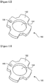
- a partition step 140 is formed at a side of the rotating part 130 opposite to the cu tout 136, as well shown in Fig. 11 .
- the partition step 140 corresponds to the partition step 108 formed on the bottom of the seating space 104 of the damper body 102, and is placed at a position corresponding to the cam surfaces 110.
- Reference numeral 142 de signates a fastening recess, and 144 designates an oil groove.
- a fixed guide plate 150 is installed such that the shaft connection boss 132 of th e rotating part 130 passes through the center thereof.
- the fixed guide plate 150 is posit ioned at the fixing recess 124 of the cover plate 120 while being relatively rotatable with respect to the rotating part 130.
- a plurality of fixing lobes 152 are formed along a per iphery of the fixed guide plate 150.
- the fixing lobes 152 are positioned in the lobe sea ting portions 124' of the fixing recess 124 so that the fixed guide plate 150 is not relativ ely rotated with respect to the cover plate 120.
- a boss passing hole 154 is formed through the center of the fixed guide plate 15 0 so that the shaft connection boss 132 of the rotating part 130 passes through the boss p assing hole.
- the shapes and dimensions of the inner surface of the boss passing hole 1 54 and the outer surface of the shaft connection boss 132 are designed so that the shaft c onnection boss 132 of the rotating part 130 can be relatively rotatably inserted into the b oss passing hole 154.
- a hole 156 is formed in one side of the fixed guide plate 150, an d a fixed end 174 of the elastic member 170, which will be explained later, is inserted an d fixed in the hole 156.
- a movable guide plate 160 is installed to the fixed guide plate 150 with the elast ic member 170, which will be explained later, interposed therebetween.
- the movable guide plate 160 is made with the same shape as the fixed guide plate 150, but not limited d thereto.
- the movable guide plate 160 is a portion by which the movable end 176 of the el astic member 170 is caught, so that the elastic member 170 can smoothly operate in coo peration with the fixed guide plate 150.
- a plurality of protruding lobes 162 are formed along a periphery of the movable guide plate 160. However, the protruding lobes 162 are not necessarily provided at the movable guide plate 160.
- a boss passing hole 164 is formed through the center of the movable guide plate 160.
- the shaft connection boss 132 is relatively rotatably installed through the boss pa ssing hole 164.
- a hole 166 is formed through one side of the movable guide plate 160.
- the movable end 176 of the elastic member 170 which will be explained later, is inse rted and caught in the hole 166.
- the fixed guide pate 150 and the movable guide plate 160 have the identical con figuration. This is to minimize the number of parts by using the parts with the same co nfiguration.
- the elastic member 170 includes a cylindrical body 172 with the fixed end 174 a nd the movable end 176 formed at both ends.
- the cylindrical body 172 is positioned b etween the guide plates 150 and 160, and the fixed end 174 and the movable end 176 are respectively caught in the holes 156 and 166 of the guide plates 150 and 160.
- the ela stic member 170 is a kind of torsion spring.
- the elastic member 170 exhibits an elasti c force in a direction in which the home-bar door is opened in an initial opening stage, a nd functions to prevent the home-bar door from being abruptly closed in a last opening s tage.
- a fastening member 180 is fastened to the oil injection hole 106 of the da mper body 102, and positioned in the fastening recess 142 of the rotating part 130.
- Thi s fastening member 180 has a body 182 with male threads formed on an outer peripheral surface thereof, and a head 184 with a relatively larger diameter is provided at one end of the body 182.
- the body 182 is fastened to the oil injection hole 106 and then inserte d into the fastening recess 142, and the head 184 functions to clog the oil injection hole 106.
- a damping fluid with high viscosity is filled in the seating space 104 of the damper body 102.
- the damping fluid disturbs the rotation of the rotating part 13 0 within the seating space 104, thereby preventing the home-bar door from being abruptl y opened.
- the damper ensures that the home-bar door is smoothly opened at an initial open ing stage of the home-bar door due to the restoring force of the elastic member 170, and also prevents the home-bar door from being abruptly opened due to its weight during the last opening stage of the home-bar door by means of the damping force of the damping fluid and the elastic force of the elastic member 170.
- FIG. 15 shows the relative positions of the rotating part 130 and the mov able end 176 of the elastic member 170 in a state where the home-bar door is closed. T his state will be explained in comparison with the state of Fig. 9.
- Fig. 9 shows that the home-bar door is opened by approximately a half. In this state, the rotating part 130 is rotated together with the home-bar door so that the movable end 176 is brought into con tact with the first wall 137.
- the elastic member 17 0 is elastically deformed and thus has a restoring force.
- the movable end 176 is separated from the first wall 137.
- the rotation of the rotating part 130 is disturbed by the damping force of the damping fluid.
- the opening speed of the home-bar door is controlled to some extent.
- the rotating part 130 continues to be rotated by the home-bar door, t he movable end 176 comes into contact with the second wall 138.
- the ho me-bar door is designed to be opened such that the movable end 176 does not come into contact with the second wall 138, the opening operation of the home-bar door ends at t hat moment.
- the home-bar door is opened until the movable end 176 com es into contact with the second wall 138, the movable end 176 is brought into contact wi th the second wall 138.
- the elast ic member 170 is elastically deformed to relatively lower the opening speed of the home -bar door.
- the fixed guide plate 150 and the movable guide plate 160 provided at the both ends of the cylindrical body 172 of the elastic member 170 function to guide the cylindrical body 172 while the elastic member 170 is operated, and also prevents noi se generation and any interference between the elastic member 170 and other parts.
- the fixed guide plate 150 is fixed to the damper body 102, more specifically to the cov er plate 120 so that it cannot be moved.
- the rotating part 130 is rotated toget her with the home-bar door, and the movable guide plate 160 is rotated together with the rotating part 130 if the movable end 176 of the elastic member 170 is brought into cont act with the first or second wall 137 or 138.
- the damper and the home-bar door using the damper accordi ng to the present invention can be installed to a door of a refrigerator.
- a ho me-bar door it is possible to take in or out an article into or from a storing space of the refrigerator without opening the refrigerator door, and the use of the damper can p revent abrupt opening of the home-bar door or any difficulty during an initial opening st age.
Landscapes
- Engineering & Computer Science (AREA)
- General Engineering & Computer Science (AREA)
- Mechanical Engineering (AREA)
- Chemical & Material Sciences (AREA)
- Combustion & Propulsion (AREA)
- Physics & Mathematics (AREA)
- Thermal Sciences (AREA)
- Refrigerator Housings (AREA)
Claims (8)
- Hausbar-Türvorrichtung für einen Kühlschrank, umfassend:einen Hausbar-Rahmen (20), der an einer Tür des Kühlschranks angebracht ist und eine Öffnung (22) aufweist, die in einer Mitte davon ausgebildet ist;eine Hausbar-Tür (30), die zum selektiven Öffnen oder Schließen der Öffnung (22) vorgesehen ist und Drehwellen (34) als Drehmittelpunkt aufweist, die von beiden Enden eines unteren Abschnitts von ihr vorstehen;Dämpfer (36), die an einer Rückseite des Hausbar-Rahmens (20) angebracht sind, um eine Öffnungs-/Schließgeschwindigkeit der Hausbar-Tür (30) zu steuern, wobei die Drehwellen (34) der Hausbar-Tür(30) in die Dämpfer (36) eingesetzt sind und relativ zu diesen gedreht werden; undDämpferhalterungen (40), die zusammen mit den Dämpfern an der Rückseite des Hausbar-Rahmens (40) montiert sind,dadurch gekennzeichnet, dass ein Paar von Dämpferhalterungsplatten (38) ausgebildet sind, um sich an beiden Enden jedes der Dämpfer (36) so zu erstrecken, dass Verlängerungsflächen der Dämpferhalterungsplatten (38) orthogonal zueinander sind,wobei der Dämpfer (100) umfasst:einen Dämpferkörper (102) mit einem darin ausgebildeten Aufnahmeraum (104);eine Abdeckplatte (120), die an einer Seite des Dämpferkörpers (102) montiert ist, um den Aufnahmeraum abzuschirmen, und die eine Befestigungsaussparung (124) aufweist, die in einer Innenfläche davon ausgebildet ist;ein innerhalb des Aufnahmeraums (104) installiertes rotierendes Teil (130), das zusammen mit der Drehachse (34) der Hausbar-Tür (30) gedreht wird;ein elastisches Element (170) zum Ausüben einer elastischen Kraft in einer ersten Öffnungsphase und einer letzten Öffnungsphase des rotierenden Teils (130);eine feststehende Führungsplatte (150), die an der Abdeckplatte (120) befestigt ist, wobei ein Ende (174) des elastischen Elements (170) an der feststehenden Führungsplatte (150) befestigt ist; undeine bewegliche Führungsplatte (160), die so angeordnet ist, dass sie der festen Führungsplatte (150) zugewandt ist, wobei das elastische Element (70) dazwischen angeordnet ist, wobei das andere Ende (176) des elastischen Elements (170) an der beweglichen Führungsplatte (160) befestigt ist, um sich selektiv zusammen mit dem rotierenden Teil (130) zu bewegen, wobei eine Dämpfungsflüssigkeit in den Aufnahmeraum (104) gefüllt ist.
- Vorrichtung nach Anspruch 1, bei der in jeder der Dämpferhalterungen (40) ein enger Kontaktabschnitt (41) zum Inkontaktbringen mit der Rückseite des Hausbar-Rahmens (20) vorgesehen ist und der enge Kontaktabschnitt (41) eine erste hintere Halterung (43) und eine seitliche Halterung (45) umfasst, die zusammen mit der Dämpferhalterungsplatte (38) am Hausbar-Rahmen (20) befestigt sind.
- Vorrichtung nach Anspruch 2, bei der die Dämpferhalterung (40) ferner mit einer zweiten hinteren Halterung (43) versehen ist, die an der Rückseite des Hausbar-Rahmens (20) montiert ist.
- Vorrichtung nach Anspruch 1, bei der der rotierende Teil (130) einen Wellenverbindungsansatz (132) mit einem Welleneinführungsabschnitt (134) aufweist, mit dem die Drehachse (34) der Hausbar-Tür (30) gekoppelt ist, wobei der Welleneinführungsabschnitt (134) durch die feststehende Führungsplatte (150), die bewegliche Führungsplatte (160) und das elastische Element (170) verläuft.
- Vorrichtung nach Anspruch 4, bei der ein Ausschnitt (136) mit einer ersten und einer zweiten Wand (137, 138), die an beiden Enden desselben ausgebildet sind, durch die ein bewegliches Ende (176) des elastischen Elements (170) selektiv gefangen wird, auf einer Oberfläche des rotierenden Teils (130) vorgesehen ist, wo der Wellenverbindungsansatz (132) ausgebildet ist, so dass das rotierende Teil (130) und die bewegliche Führungsplatte (160) selektiv integral bewegt werden.
- Vorrichtung nach Anspruch 5, bei der der Welleneinführungsabschnitt (134), der in dem Wellenverbindungsansatz (132) des rotierenden Teils (130) ausgebildet ist, durch ein Durchgangsloch (126), das durch eine Mitte der Abdeckplatte (120) hindurch gebildet ist, nach außen freigelegt ist.
- Vorrichtung nach einem der Ansprüche 1 bis 6, bei der mindestens eine der Drehwellen (34) der Hausbar-Tür (30) vorsteht und von einer Feder in einer Richtung, in der die Drehwelle aus der Hausbar-Tür vorsteht, gestützt wird.
- Vorrichtung nach Anspruch 1, ferner umfassend Dämpferhalterungsplatten (112), die auf einer Außenfläche des Dämpferkörpers (102) vorgesehen sind, wobei sich die Dämpferhalterungsplatten (112) von beiden Enden des Dämpferkörpers (102) in entgegengesetzte Richtungen so erstrecken, dass Verlängerungsflächen derselben orthogonal zueinander sind.
Applications Claiming Priority (3)
| Application Number | Priority Date | Filing Date | Title |
|---|---|---|---|
| KR1020050088937A KR101130432B1 (ko) | 2005-09-23 | 2005-09-23 | 냉장고의 홈바도어장치 |
| KR1020060024955A KR100756702B1 (ko) | 2006-03-17 | 2006-03-17 | 냉장고용 힌지 조립체 |
| PCT/KR2006/003758 WO2007035049A1 (en) | 2005-09-23 | 2006-09-21 | Damper and home-bar door apparatus for refrigerator using the same |
Publications (3)
| Publication Number | Publication Date |
|---|---|
| EP1946025A1 EP1946025A1 (de) | 2008-07-23 |
| EP1946025A4 EP1946025A4 (de) | 2016-12-28 |
| EP1946025B1 true EP1946025B1 (de) | 2019-11-20 |
Family
ID=37889057
Family Applications (1)
| Application Number | Title | Priority Date | Filing Date |
|---|---|---|---|
| EP06798841.0A Not-in-force EP1946025B1 (de) | 2005-09-23 | 2006-09-21 | Dämpfer und heimbartürvorrichtung für diese(n) verwendenden kühlschrank |
Country Status (4)
| Country | Link |
|---|---|
| US (1) | US7980644B2 (de) |
| EP (1) | EP1946025B1 (de) |
| AU (1) | AU2006292904B2 (de) |
| WO (1) | WO2007035049A1 (de) |
Families Citing this family (16)
| Publication number | Priority date | Publication date | Assignee | Title |
|---|---|---|---|---|
| WO2006098591A1 (en) * | 2005-03-16 | 2006-09-21 | Lg Electronics Inc. | Damper embedded in a home bar door of a refrigerator and method for manufacturing the same |
| KR20060106338A (ko) * | 2005-04-08 | 2006-10-12 | 엘지전자 주식회사 | 홈바도어를 구비하는 냉장고 |
| KR20080012687A (ko) * | 2006-08-04 | 2008-02-12 | 엘지전자 주식회사 | 냉장고의 홈바도어 작동 구조 |
| KR101275568B1 (ko) * | 2006-10-24 | 2013-06-14 | 엘지전자 주식회사 | 자동홈바 |
| CN101231075B (zh) * | 2007-01-24 | 2011-07-06 | 泰州乐金电子冷机有限公司 | 泡菜冰箱的显示装置 |
| KR101329489B1 (ko) * | 2007-04-04 | 2013-11-13 | 엘지전자 주식회사 | 냉장고용 홈바 |
| DE102008026383A1 (de) * | 2008-06-02 | 2009-12-03 | BSH Bosch und Siemens Hausgeräte GmbH | Haushaltsgerät mit einer eine Bremsvorrichtung aufweisenden Tür |
| KR20100037764A (ko) * | 2008-10-02 | 2010-04-12 | 삼성전자주식회사 | 냉장고 |
| JP2010203695A (ja) * | 2009-03-04 | 2010-09-16 | Panasonic Corp | 冷蔵庫 |
| DE102009028434A1 (de) * | 2009-08-10 | 2011-02-17 | BSH Bosch und Siemens Hausgeräte GmbH | Einbaubehälter für ein Kältegerät |
| KR20110090157A (ko) * | 2010-02-03 | 2011-08-10 | 삼성전자주식회사 | 홈바도어 및 이를 갖는 냉장고 |
| DE102011002982B4 (de) * | 2011-01-21 | 2022-05-25 | Robert Bosch Gmbh | Federelement und korrespondierende Kolbenpumpe zur Förderung von Fluiden |
| KR20150005060A (ko) * | 2013-07-04 | 2015-01-14 | 동부대우전자 주식회사 | 세탁기 |
| KR20160045545A (ko) * | 2014-10-17 | 2016-04-27 | 엘지전자 주식회사 | 냉장고 |
| CN109681063B (zh) * | 2018-12-21 | 2024-01-30 | 江苏玖星精密科技集团有限公司 | 一种具有阻尼缓冲结构的冰箱门铰链 |
| CN114777373B (zh) * | 2022-04-26 | 2024-06-25 | 浙江三花智能控制股份有限公司 | 一种冰箱的风门装置 |
Family Cites Families (21)
| Publication number | Priority date | Publication date | Assignee | Title |
|---|---|---|---|---|
| AU624027B2 (en) * | 1989-10-11 | 1992-05-28 | Sugatsune Industrial Co., Ltd | Door hinge |
| US5419013A (en) * | 1993-12-10 | 1995-05-30 | Hsiao; Chun-Sung | Hydraulic hinge having rotatable shaft and linearly movable plug forming fluid chambers |
| KR100250050B1 (ko) * | 1997-07-03 | 2000-04-01 | 정몽규 | V형 엔진의 가변 흡기시스템 |
| JP2001500605A (ja) * | 1997-07-03 | 2001-01-16 | ゼネラル・エレクトリック・カンパニイ | 冷蔵庫の冷蔵室用のモジュール式リフレッシュメント・センタ |
| KR200165714Y1 (ko) | 1997-08-09 | 2000-01-15 | 구자홍 | 냉장고의 홈바 도어 결합구조 |
| KR100475012B1 (ko) * | 1997-10-08 | 2005-04-14 | 삼성전자주식회사 | 그룹데이터에대한산술연산을수행하는64비트산술연산기 |
| KR19990031097U (ko) | 1997-12-30 | 1999-07-26 | 구자홍 | 냉장고의 홈바 |
| KR100857605B1 (ko) | 2002-11-27 | 2008-09-09 | 삼성전자주식회사 | 냉장고 |
| KR200307805Y1 (ko) | 2002-12-27 | 2003-03-19 | 한라정밀 주식회사 | 다용도 힌지장치 |
| KR20040080070A (ko) * | 2003-03-10 | 2004-09-18 | 엘지전자 주식회사 | 오일댐퍼를 적용한 홈바도어를 구비하는 냉장고 |
| US7360278B2 (en) * | 2003-12-19 | 2008-04-22 | Lg Electronics Inc. | Home-bar door opening/closing device for refrigerator |
| KR101195877B1 (ko) * | 2005-01-14 | 2012-10-30 | 삼성전자주식회사 | 냉장고 |
| US20060226750A1 (en) * | 2005-04-08 | 2006-10-12 | Lee Jeong Y | Refrigerator having home bar |
| KR20060106338A (ko) * | 2005-04-08 | 2006-10-12 | 엘지전자 주식회사 | 홈바도어를 구비하는 냉장고 |
| KR20080089725A (ko) * | 2007-04-02 | 2008-10-08 | 엘지전자 주식회사 | 홈바도어 및 이의 제조방법 |
| KR101329489B1 (ko) * | 2007-04-04 | 2013-11-13 | 엘지전자 주식회사 | 냉장고용 홈바 |
| US7596830B2 (en) * | 2007-09-06 | 2009-10-06 | Cheng Uei Precision Industry Co., Ltd. | Hinge |
| KR100875475B1 (ko) * | 2007-12-18 | 2008-12-22 | 동우정밀(주) | 냉장고의 홈바 도어를 위한 힌지 어셈블리와 이를 이용한냉장고 |
| US7484266B1 (en) * | 2007-12-31 | 2009-02-03 | Cheng Uei Precision Industry Co., Ltd. | Hinge apparatus |
| US8182055B2 (en) * | 2008-04-22 | 2012-05-22 | Samsung Electronics Co., Ltd. | Damping unit and refrigerator having the same |
| KR20100037764A (ko) * | 2008-10-02 | 2010-04-12 | 삼성전자주식회사 | 냉장고 |
-
2006
- 2006-09-21 WO PCT/KR2006/003758 patent/WO2007035049A1/en not_active Ceased
- 2006-09-21 AU AU2006292904A patent/AU2006292904B2/en not_active Ceased
- 2006-09-21 EP EP06798841.0A patent/EP1946025B1/de not_active Not-in-force
- 2006-09-21 US US12/067,791 patent/US7980644B2/en active Active
Non-Patent Citations (1)
| Title |
|---|
| None * |
Also Published As
| Publication number | Publication date |
|---|---|
| US20080252191A1 (en) | 2008-10-16 |
| AU2006292904B2 (en) | 2009-11-05 |
| EP1946025A1 (de) | 2008-07-23 |
| WO2007035049A1 (en) | 2007-03-29 |
| US7980644B2 (en) | 2011-07-19 |
| AU2006292904A1 (en) | 2007-03-29 |
| EP1946025A4 (de) | 2016-12-28 |
| WO2007035049A9 (en) | 2008-05-29 |
Similar Documents
| Publication | Publication Date | Title |
|---|---|---|
| EP1946025B1 (de) | Dämpfer und heimbartürvorrichtung für diese(n) verwendenden kühlschrank | |
| US7360278B2 (en) | Home-bar door opening/closing device for refrigerator | |
| EP3086058B1 (de) | Kühlschrank | |
| JP7474839B2 (ja) | 自由ビルトイン式冷蔵庫 | |
| CN110542268B (zh) | 冰箱 | |
| KR101203424B1 (ko) | 냉장고 | |
| KR20130105065A (ko) | 냉장고 | |
| JP2010249491A (ja) | 冷蔵庫 | |
| JP7474840B2 (ja) | 開放度を高めるフリービルトイン式冷蔵庫 | |
| KR20200132608A (ko) | 냉장고 | |
| EP3726169B1 (de) | Kühlschrank | |
| EP1691153A1 (de) | Kühlgerät | |
| US8356866B2 (en) | Refrigerator with door opening device | |
| KR20080038631A (ko) | 냉장고용 도어의 댐핑구조 | |
| CN101660380B (zh) | 阻尼器 | |
| EP2717003B1 (de) | Türschliessstruktur für sich drehende kühlschranktür und side-by-side-kühl-gefrierkombination damit | |
| KR20180080084A (ko) | 냉장고 | |
| JP3889590B2 (ja) | 冷蔵庫 | |
| KR102929915B1 (ko) | 냉장고 및 냉장고 도어 | |
| KR101669419B1 (ko) | 김치냉장고 | |
| KR100243045B1 (ko) | 냉장고의 도어구조 | |
| GB2438766A (en) | Home-bar opening/closing device for refrigerator | |
| JPH09264661A (ja) | 冷蔵庫 | |
| KR100755319B1 (ko) | 냉장고의 개스킷 분리 장치 | |
| KR200336422Y1 (ko) | 홈바용 도어 링크장치의 소음 저감구조 |
Legal Events
| Date | Code | Title | Description |
|---|---|---|---|
| PUAI | Public reference made under article 153(3) epc to a published international application that has entered the european phase |
Free format text: ORIGINAL CODE: 0009012 |
|
| 17P | Request for examination filed |
Effective date: 20080307 |
|
| AK | Designated contracting states |
Kind code of ref document: A1 Designated state(s): DE GB IT |
|
| RBV | Designated contracting states (corrected) |
Designated state(s): DE GB IT |
|
| DAX | Request for extension of the european patent (deleted) | ||
| RA4 | Supplementary search report drawn up and despatched (corrected) |
Effective date: 20161130 |
|
| RIC1 | Information provided on ipc code assigned before grant |
Ipc: E05F 3/14 20060101ALI20161124BHEP Ipc: E05F 3/20 20060101ALI20161124BHEP Ipc: F25D 25/00 20060101AFI20161124BHEP Ipc: E05D 7/081 20060101ALI20161124BHEP Ipc: F25D 23/02 20060101ALI20161124BHEP Ipc: F16F 9/12 20060101ALI20161124BHEP |
|
| 17Q | First examination report despatched |
Effective date: 20181129 |
|
| GRAP | Despatch of communication of intention to grant a patent |
Free format text: ORIGINAL CODE: EPIDOSNIGR1 |
|
| INTG | Intention to grant announced |
Effective date: 20190619 |
|
| GRAS | Grant fee paid |
Free format text: ORIGINAL CODE: EPIDOSNIGR3 |
|
| GRAA | (expected) grant |
Free format text: ORIGINAL CODE: 0009210 |
|
| AK | Designated contracting states |
Kind code of ref document: B1 Designated state(s): DE GB IT |
|
| REG | Reference to a national code |
Ref country code: GB Ref legal event code: FG4D |
|
| REG | Reference to a national code |
Ref country code: DE Ref legal event code: R096 Ref document number: 602006058852 Country of ref document: DE |
|
| REG | Reference to a national code |
Ref country code: DE Ref legal event code: R097 Ref document number: 602006058852 Country of ref document: DE |
|
| PLBE | No opposition filed within time limit |
Free format text: ORIGINAL CODE: 0009261 |
|
| STAA | Information on the status of an ep patent application or granted ep patent |
Free format text: STATUS: NO OPPOSITION FILED WITHIN TIME LIMIT |
|
| 26N | No opposition filed |
Effective date: 20200821 |
|
| PG25 | Lapsed in a contracting state [announced via postgrant information from national office to epo] |
Ref country code: IT Free format text: LAPSE BECAUSE OF FAILURE TO SUBMIT A TRANSLATION OF THE DESCRIPTION OR TO PAY THE FEE WITHIN THE PRESCRIBED TIME-LIMIT Effective date: 20191120 |
|
| GBPC | Gb: european patent ceased through non-payment of renewal fee |
Effective date: 20200921 |
|
| PG25 | Lapsed in a contracting state [announced via postgrant information from national office to epo] |
Ref country code: GB Free format text: LAPSE BECAUSE OF NON-PAYMENT OF DUE FEES Effective date: 20200921 |
|
| PGFP | Annual fee paid to national office [announced via postgrant information from national office to epo] |
Ref country code: DE Payment date: 20230807 Year of fee payment: 18 |
|
| REG | Reference to a national code |
Ref country code: DE Ref legal event code: R119 Ref document number: 602006058852 Country of ref document: DE |
|
| PG25 | Lapsed in a contracting state [announced via postgrant information from national office to epo] |
Ref country code: DE Free format text: LAPSE BECAUSE OF NON-PAYMENT OF DUE FEES Effective date: 20250401 |