EP1959319A1 - Magnetically-regulated watch - Google Patents
Magnetically-regulated watch Download PDFInfo
- Publication number
- EP1959319A1 EP1959319A1 EP06841787A EP06841787A EP1959319A1 EP 1959319 A1 EP1959319 A1 EP 1959319A1 EP 06841787 A EP06841787 A EP 06841787A EP 06841787 A EP06841787 A EP 06841787A EP 1959319 A1 EP1959319 A1 EP 1959319A1
- Authority
- EP
- European Patent Office
- Prior art keywords
- crown
- magnetic
- holder
- case
- magnetic elements
- Prior art date
- Legal status (The legal status is an assumption and is not a legal conclusion. Google has not performed a legal analysis and makes no representation as to the accuracy of the status listed.)
- Granted
Links
Images

Classifications
-
- G—PHYSICS
- G04—HOROLOGY
- G04C—ELECTROMECHANICAL CLOCKS OR WATCHES
- G04C3/00—Electromechanical clocks or watches independent of other time-pieces and in which the movement is maintained by electric means
- G04C3/001—Electromechanical switches for setting or display
- G04C3/004—Magnetically controlled
-
- G—PHYSICS
- G04—HOROLOGY
- G04B—MECHANICALLY-DRIVEN CLOCKS OR WATCHES; MECHANICAL PARTS OF CLOCKS OR WATCHES IN GENERAL; TIME PIECES USING THE POSITION OF THE SUN, MOON OR STARS
- G04B27/00—Mechanical devices for setting the time indicating means
- G04B27/08—Mechanical devices for setting the time indicating means by using parts of the case
-
- G—PHYSICS
- G04—HOROLOGY
- G04C—ELECTROMECHANICAL CLOCKS OR WATCHES
- G04C3/00—Electromechanical clocks or watches independent of other time-pieces and in which the movement is maintained by electric means
- G04C3/14—Electromechanical clocks or watches independent of other time-pieces and in which the movement is maintained by electric means incorporating a stepping motor
Definitions
- the present invention relates to a watch that comprises a movement or machine, a case and a holder that solidly houses the movement and is arranged inside the case.
- a previous PCT application filed by the applicant and published as WO 2005/045534 discloses a watch devoid of a stem comprising a movement, a cover that lends support to said movement, and a middle of the watch-case that surrounds said machine.
- the time-setting the movement is integral with the cover and the assembly of both elements is rotatably mounted with respect to the middle, so that at least one hand of the watch can be set by rotating said assembly with respect to the middle in a first sense of rotation.
- the watch comprises blocking means for blocking at least one hand with respect to the middle when said assembly is rotated in a second sense of rotation opposite to the fist sense of rotation. This arrangement allows time-setting one hand by rotating the movement in a sense, and time-setting the other hand without moving the previous one by rotating the movement in the opposite sense.
- This arrangement presents some difficulty in making the watch perfectly waterproof, for instance when used in underwater diving, because the cover and the middle are distinct pieces between which a sealing gasket is placed, and, since the operation of the watch involves rotating often the cover with respect to the middle, said gasket can deteriorate and lose its sealing ability.
- such a watch comprises a crown that surrounds the case, and magnetic means for establishing a magnetic relationship between the crown and the holder, so that upon rotation of the crown with respect to the case a corresponding rotation of the holder with respect to the case, and thus of the movement with respect to the case, is produced.
- This allows to time-set the watch without the intervention of any mechanical link between the outside and the inside of the case.
- said magnetic relationship is established by incorporating one or several magnetic elements in the crown, in the holder or in both. If the crown or the holder does not include any magnetic element, then it will include magnetizable elements, to be dragged by the magnetic elements of the other.
- At least one of the magnetic elements of the crown is screened from the outside by a small plate made of a ferromagnetic material, the small plate being magnetically linked to said magnetic element.
- the magnetic elements of the crown concentrate their magnetic flux towards the holder inside the case.
- the crown is provided with one or several magnetic elements and the holder is provided with one or several magnetic elements in correspondence with the magnetic elements of the crown, so that by rotating the crown with respect to the case the subsequent rotation of the magnetic fields of the magnetic elements of the crown produces a corresponding rotation of the magnetic elements of the holder and of the holder itself and, consequently, of the movement with respect to the case.
- the magnetic elements of the crown are arranged along the crown's perimeter with their magnetic axes substantially radially oriented, and, advantageously, said magnetic elements are also arranged so that their magnetic poles successively alternate.
- the magnetic elements of the holder are arranged along the holder's perimeter with their magnetic axes substantially radially oriented, and are also arranged so that their magnetic poles successively alternate. In this way, the magnetic relationship between the magnetic elements of the crown and the magnetic elements of the holder is optimal.
- both the magnetic elements of the crown and the holder are of neodymium.
- the holder comprises a sleeve of a ferromagnetic material rigidly connected to it. Then the magnetic elements of the holder are simply magnetically linked to the sleeve. The sleeve, moreover, screens said magnetic elements with respect to the movement and greatly reduces the small magnetic influence that the former might have on the latter.
- the case can be formed as a single piece, shaped like a cup with one opening for sealingly fitting the glass, so that the watch can be waterproof at great depths.
- All the forms of the invention can be advantageously applied to a watch devoid of a time-setting stem wherein the movement can be rotated with respect to the case.
- FIGS 1 and 2 show an embodiment of a watch according to the invention; the glass, the bezel, the dial and the hands are not represented.
- Said watch comprises a movement 1 solidly housed in a holder 3, i.e., the movement 1 is rigidly connected to the holder 3; the latter is in turn is rotatably housed in a watch-case 2.
- the case 2 is made in one piece, that is, includes in a single element the middle and the cover of the watch.
- the lower portion of the watch-case 2 presents a peripheral recess 9 (see figure 3 ) and a projection 10.
- a ring-shaped crown 4 is housed in said recess 9, so that its central hollow 11 (see figure 4 ) rotatably fits the projection 10.
- the crown 4 is provided with a plurality of radial holes 12 (two of them are shown in figure 1 ) spaced along its perimeter.
- Each hole 12 houses a magnetic element or magnet 5 the magnetic axis of which follows the radial direction.
- the arrangement of magnets 5 is such that the magnetic poles are successively alternating, that is, two contiguous magnets have their N-S polarity inverted with respect to each other.
- the lower portion of the holder 3 has an annular shaped recess 7, which leaves a ring 8 in the periphery of said lower portion of the holder 3.
- the ring 8 is provided with a plurality of radial holes 13 (two of them are shown in figure 1 ) spaced along its perimeter.
- Each hole 13 houses a magnetic element or magnet 6 the magnetic axis of which follows the radial direction.
- the arrangement of magnets 6 is such that the magnetic poles are successively alternating, that is, two contiguous magnets have their N-S polarity inverted with respect to each other.
- the two pluralities of magnets 5 and 6 are concentrically arranged and substantially at the same height.
- This rotation of the movement 1 can be applied, for example, to time-set a watch according to the applicant's disclosure in WO 2005/045534 , which is hereby incorporated by reference.
- the same distance-action system between the outside and the inside of the watch can also be applied to the rotation of the decompression ring of a watch for underwater diving.
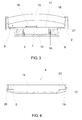
- FIGS 3 and 4 show another embodiment of a watch according to the invention.
- the general configuration of this embodiment is similar to that of the previous embodiment, and corresponding elements have the same reference numeral.
- the movement 1 and the holder 3 are arranged inside the projection 10 of the watch-case 2, and said holder 3 is like a sleeve.
- a sleeve 14 is fitted on the holder 3, so that the two elements are made integral.
- the sleeve 14 is made of a ferromagnetic material (for example iron) and the magnets 6 of the holder 3 are peripherally arranged on it (although in the figure they are shown under the sleeve 14). Said magnets 6 are magnetically linked to the sleeve 14.
- the crown 4 of figure 4 is like a plate or disk provided with a peripheral shoulder 22. Like in the previous embodiment, the crown 4 is provided with a plurality of radial holes 12 spaced along its perimeter; the magnets 5 are placed in said holes 12. Each magnet 5 is screened from the outside by a small plate 19 made of a ferromagnetic material that is magnetically linked to the magnet. A protrusion 20 is arranged on each small plate 19; said protrusion 20 projects from the hole 12 and allows to firmly grasp the crown 4, in order to readily rotate it with respect to the watch-case 2.
- the watch also comprises a glass 15 thick enough to resist high pressures, like the pressure exerted by deep water.
- Said glass 15 is fitted on a frusto-conical inner wall of the watch-case 2, so that the higher the pressure on the glass the higher it is pushed against the watch-case and the more perfect the sealing is (the fitting between the glass and the watch-case is the only seal of the watch, since the watch-case is a single piece).
- an inverted frusto-conical engagement between the glass 15 and the watch-case 2 is provided to guarantee the waterproof sealing of the watch, because said engagement is tighter as higher is the pressure on the glass, so that it is not necessary to arrange a gasket between the glass and the watch-case.
- a dial 17, two hands 18 and a bezel 16 fastened to the watch-case 2 through a thread 21 are also represented in figure 3 , even though they are not directly related to the present invention.
- either the crown 4 or the holder 3 incorporates magnetizable elements (that can be attracted by a magnetic field and can be made for instance of a ferromagnetic material) instead of magnetic elements, on the condition that the other one, be it either the holder or the crown, may incorporate magnetic elements.
- magnetizable elements that can be attracted by a magnetic field and can be made for instance of a ferromagnetic material
- the magnets 5 and 6 are preferably of neodymium and present a cylindrical shape.
- the rest of elements of the invention, except the sleeve 14 and the small plates 19, are made of non-magnetizable materials (such as, for example, brass or gold).
- the crown 4 can be shaped as a disk or plate with a peripheral shoulder (said shoulder providing the crown-like functionality), or else it can surround the watch-case 2 at another position different from the bottom one.
- the magnetic elements 5 or 6 can have any shape or arrangement that is suitable for its functionality.
- magnetic or magnetizable materials incorporated to the crown 4 and the holder 3 can be any material suitable for its intended functionality.
Landscapes
- Physics & Mathematics (AREA)
- General Physics & Mathematics (AREA)
- Electric Clocks (AREA)
- Polysaccharides And Polysaccharide Derivatives (AREA)
- Stabilization Of Oscillater, Synchronisation, Frequency Synthesizers (AREA)
- Electromechanical Clocks (AREA)
Abstract
Description
- The present invention relates to a watch that comprises a movement or machine, a case and a holder that solidly houses the movement and is arranged inside the case.
- There are known in the art wristwatches provided with an external crown coupled to a stem that acts mechanically on the hands of the watch, in order to allow the time-setting. This time-setting system is not very convenient because the stem has to cut through the whole movement and this seriously limits the watch design.
- A previous
PCT application filed by the applicant and published as WO 2005/045534 discloses a watch devoid of a stem comprising a movement, a cover that lends support to said movement, and a middle of the watch-case that surrounds said machine. During the time-setting the movement is integral with the cover and the assembly of both elements is rotatably mounted with respect to the middle, so that at least one hand of the watch can be set by rotating said assembly with respect to the middle in a first sense of rotation. The watch comprises blocking means for blocking at least one hand with respect to the middle when said assembly is rotated in a second sense of rotation opposite to the fist sense of rotation. This arrangement allows time-setting one hand by rotating the movement in a sense, and time-setting the other hand without moving the previous one by rotating the movement in the opposite sense. - This arrangement presents some difficulty in making the watch perfectly waterproof, for instance when used in underwater diving, because the cover and the middle are distinct pieces between which a sealing gasket is placed, and, since the operation of the watch involves rotating often the cover with respect to the middle, said gasket can deteriorate and lose its sealing ability.
- It is an object of the present invention to provide a watch devoid of the conventional time-setting stem that is perfectly waterproof even at high depths.
- In the following, coherently with the term used in horology for indicating an element of the time-setting mechanism, "crown" will mean an element driving the time-setting device, independently of the concrete form that it may adopt.
- Then, according to one aspect of the invention, such a watch comprises a crown that surrounds the case, and magnetic means for establishing a magnetic relationship between the crown and the holder, so that upon rotation of the crown with respect to the case a corresponding rotation of the holder with respect to the case, and thus of the movement with respect to the case, is produced. This allows to time-set the watch without the intervention of any mechanical link between the outside and the inside of the case.
- Preferably, said magnetic relationship is established by incorporating one or several magnetic elements in the crown, in the holder or in both. If the crown or the holder does not include any magnetic element, then it will include magnetizable elements, to be dragged by the magnetic elements of the other.
- Advantageously, at least one of the magnetic elements of the crown is screened from the outside by a small plate made of a ferromagnetic material, the small plate being magnetically linked to said magnetic element. In this way, the magnetic elements of the crown concentrate their magnetic flux towards the holder inside the case.
- In an embodiment, the crown is provided with one or several magnetic elements and the holder is provided with one or several magnetic elements in correspondence with the magnetic elements of the crown, so that by rotating the crown with respect to the case the subsequent rotation of the magnetic fields of the magnetic elements of the crown produces a corresponding rotation of the magnetic elements of the holder and of the holder itself and, consequently, of the movement with respect to the case.
- Preferably, the magnetic elements of the crown are arranged along the crown's perimeter with their magnetic axes substantially radially oriented, and, advantageously, said magnetic elements are also arranged so that their magnetic poles successively alternate. Analogously, the magnetic elements of the holder are arranged along the holder's perimeter with their magnetic axes substantially radially oriented, and are also arranged so that their magnetic poles successively alternate. In this way, the magnetic relationship between the magnetic elements of the crown and the magnetic elements of the holder is optimal.
- Besides, the radial arrangement of said magnetic elements does not affect the working of the internal mechanisms of the movement.
- Advantageously, both the magnetic elements of the crown and the holder are of neodymium.
- In an embodiment, the holder comprises a sleeve of a ferromagnetic material rigidly connected to it. Then the magnetic elements of the holder are simply magnetically linked to the sleeve. The sleeve, moreover, screens said magnetic elements with respect to the movement and greatly reduces the small magnetic influence that the former might have on the latter.
- With the described arrangement the case can be formed as a single piece, shaped like a cup with one opening for sealingly fitting the glass, so that the watch can be waterproof at great depths.
- All the forms of the invention can be advantageously applied to a watch devoid of a time-setting stem wherein the movement can be rotated with respect to the case.
- Some particular embodimente of the present invention will be described in the following, only by way of non-limiting example, with reference to the appended drawings, in which:
-
figure 1 is a view from below of a watch according to the invention; -
figure 2 is a side cross-section view taken along the line II-II offigure 1 ; -
figure 3 is a side cross-section view, similar to that offigure 2 , of another embodiment; and -
figure 4 is a side cross-section view of another element of the embodiment showed infigure 3 . -
Figures 1 and 2 show an embodiment of a watch according to the invention; the glass, the bezel, the dial and the hands are not represented. Said watch comprises amovement 1 solidly housed in aholder 3, i.e., themovement 1 is rigidly connected to theholder 3; the latter is in turn is rotatably housed in a watch-case 2. Thecase 2 is made in one piece, that is, includes in a single element the middle and the cover of the watch. - The lower portion of the watch-
case 2 presents a peripheral recess 9 (seefigure 3 ) and aprojection 10. A ring-shaped crown 4 is housed in saidrecess 9, so that its central hollow 11 (seefigure 4 ) rotatably fits theprojection 10. - The
crown 4 is provided with a plurality of radial holes 12 (two of them are shown infigure 1 ) spaced along its perimeter. Eachhole 12 houses a magnetic element ormagnet 5 the magnetic axis of which follows the radial direction. The arrangement ofmagnets 5 is such that the magnetic poles are successively alternating, that is, two contiguous magnets have their N-S polarity inverted with respect to each other. - The lower portion of the
holder 3 has an annularshaped recess 7, which leaves aring 8 in the periphery of said lower portion of theholder 3. As thecrown 4, thering 8 is provided with a plurality of radial holes 13 (two of them are shown infigure 1 ) spaced along its perimeter. Eachhole 13 houses a magnetic element ormagnet 6 the magnetic axis of which follows the radial direction. The arrangement ofmagnets 6 is such that the magnetic poles are successively alternating, that is, two contiguous magnets have their N-S polarity inverted with respect to each other. - The two pluralities of
magnets - In this way, if the
crown 4 is rotated with respect to the watch-case 2, then the rotation of the magnetic fields ofmagnets 5 ofcrown 4 makes themagnets 6 ofholder 3 to follow said rotation, and thus makes theholder 3 to rotate correspondingly, thereby resulting in a rotation of themovement 1 with respect to the watch-case 2 in correspondence with the rotation of thecrown 4. - This rotation of the
movement 1 can be applied, for example, to time-set a watch according to the applicant's disclosure inWO 2005/045534 , which is hereby incorporated by reference. - The same distance-action system between the outside and the inside of the watch can also be applied to the rotation of the decompression ring of a watch for underwater diving.
-
Figures 3 and 4 show another embodiment of a watch according to the invention. The general configuration of this embodiment is similar to that of the previous embodiment, and corresponding elements have the same reference numeral. - In the embodiment of
figures 3 and 4 , themovement 1 and theholder 3 are arranged inside theprojection 10 of the watch-case 2, and saidholder 3 is like a sleeve. Asleeve 14 is fitted on theholder 3, so that the two elements are made integral. Thesleeve 14 is made of a ferromagnetic material (for example iron) and themagnets 6 of theholder 3 are peripherally arranged on it (although in the figure they are shown under the sleeve 14). Saidmagnets 6 are magnetically linked to thesleeve 14. - The
crown 4 offigure 4 is like a plate or disk provided with aperipheral shoulder 22. Like in the previous embodiment, thecrown 4 is provided with a plurality ofradial holes 12 spaced along its perimeter; themagnets 5 are placed in saidholes 12. Eachmagnet 5 is screened from the outside by asmall plate 19 made of a ferromagnetic material that is magnetically linked to the magnet. Aprotrusion 20 is arranged on eachsmall plate 19; saidprotrusion 20 projects from thehole 12 and allows to firmly grasp thecrown 4, in order to readily rotate it with respect to the watch-case 2. - The operation of this embodiment is like the operation of the previous embodiment.
- The watch also comprises a
glass 15 thick enough to resist high pressures, like the pressure exerted by deep water.Said glass 15 is fitted on a frusto-conical inner wall of the watch-case 2, so that the higher the pressure on the glass the higher it is pushed against the watch-case and the more perfect the sealing is (the fitting between the glass and the watch-case is the only seal of the watch, since the watch-case is a single piece). - In general, an inverted frusto-conical engagement between the
glass 15 and the watch-case 2 is provided to guarantee the waterproof sealing of the watch, because said engagement is tighter as higher is the pressure on the glass, so that it is not necessary to arrange a gasket between the glass and the watch-case. - A
dial 17, twohands 18 and abezel 16 fastened to the watch-case 2 through athread 21 are also represented infigure 3 , even though they are not directly related to the present invention. - In an embodiment, either the
crown 4 or theholder 3 incorporates magnetizable elements (that can be attracted by a magnetic field and can be made for instance of a ferromagnetic material) instead of magnetic elements, on the condition that the other one, be it either the holder or the crown, may incorporate magnetic elements. This is feasible because for a watch according to the invention to be operated it is only necessary to establish, by any means, a magnetic relationship between thecrown 4 and theholder 3. - The
magnets sleeve 14 and thesmall plates 19, are made of non-magnetizable materials (such as, for example, brass or gold). - Although only particular embodiments of the invention have been shown and described in the present specification, the skilled man will be able to introduce modifications and substitute any technical features thereof with others that are technically equivalent, depending on the particular requirements of each case, without departing from the scope of protection defined by the appended claims.
- For example, it has already been mentioned that the
crown 4 can be shaped as a disk or plate with a peripheral shoulder (said shoulder providing the crown-like functionality), or else it can surround the watch-case 2 at another position different from the bottom one. - Or, for example, the
magnetic elements - It is also clear that the magnetic or magnetizable materials incorporated to the
crown 4 and theholder 3 can be any material suitable for its intended functionality.
Claims (15)
- Watch comprising a movement (1), a case (2) and a holder (3, 14) that solidly houses the movement (1) and is arranged inside the case (2), characterized in that it also comprises a crown (4) that surrounds the case (2), and magnetic means (5; 6) for establishing a magnetic relationship between the crown (4) and the holder (3, 14), so that upon rotation of the crown (4) with respect to the case (2) a corresponding rotation of the holder (3, 14) with respect to the case (2), and thus of the movement (1) with respect to the case (2), is produced.
- Watch according to claim 1, wherein said magnetic means for establishing a magnetic relationship between the crown (4) and the holder (3, 14) comprises one or several magnetic elements (5) in the crown (4).
- Watch according to claim 2, wherein at least one of the magnetic elements (5) of the crown (4) is screened from the outside by a small plate (19) made of a ferromagnetic material, the small plate (19) being magnetically linked to said magnetic element (5).
- Watch according to any of the preceding elements, wherein said magnetic means for establishing a magnetic relationship between the crown (4) and the holder (3, 14) comprises one or several magnetic elements (6) in the holder (3, 14).
- Watch according to any of the preceding elements, wherein the crown (4) is provided with one or several magnetic elements (5) and the holder (3, 14) is provided with one or several magnetic elements (6) in correspondence with the magnetic elements (5) of the crown (4), so that by rotating the crown (4) with respect to the case (2) the subsequent rotation of the magnetic fields of the magnetic elements (5) of the crown (4) produces a corresponding rotation of the magnetic elements (6) of the holder (3, 14) and, consequently, of the movement (1) with respect to the case (2).
- Watch according to claim 2, 3 or 5, wherein the magnetic elements (5) of the crown (4) are arranged along the crown's perimeter with their magnetic axes substantially radially oriented.
- Watch according to claim 6, wherein the magnetic elements (5) of the crown (4) are arranged so that their magnetic poles successively alternate.
- Watch according claim 4 or 5, wherein the magnetic elements (6) of the holder (3, 14) are arranged along the holder's perimeter with their magnetic axes substantially radially oriented.
- Watch according to claim 8, wherein the magnetic elements (6) of the holder (3, 14) are arranged so that their magnetic poles successively alternate.
- Watch according to any of claims 2 to 9, wherein at least one of said magnetic elements (5, 6) is of neodymium.
- Watch according to any of the preceding claims, wherein the holder (3) comprises a sleeve (14) rigidly connected to it.
- Watch according to any of the preceding claims, wherein the sleeve (14) is of ferromagnetic material.
- Watch according to claim 12, wherein the magnetic elements (6) of the holder (3) are magnetically linked to the sleeve (14).
- Watch according to any of the preceding claims, wherein the case (2) is formed as a single piece.
- Watch according to any of the preceding claims, which is devoid of a time-setting stem and wherein the movement (1) can be rotated with respect to the case (2).
Applications Claiming Priority (2)
| Application Number | Priority Date | Filing Date | Title |
|---|---|---|---|
| ES200502641U ES1061716Y (en) | 2005-11-25 | 2005-11-25 | WATCH. |
| PCT/ES2006/070180 WO2007060277A1 (en) | 2005-11-25 | 2006-11-22 | Magnetically-regulated watch |
Publications (2)
| Publication Number | Publication Date |
|---|---|
| EP1959319A1 true EP1959319A1 (en) | 2008-08-20 |
| EP1959319B1 EP1959319B1 (en) | 2011-02-09 |
Family
ID=36101385
Family Applications (1)
| Application Number | Title | Priority Date | Filing Date |
|---|---|---|---|
| EP06841787A Not-in-force EP1959319B1 (en) | 2005-11-25 | 2006-11-22 | Magnetically-regulated watch |
Country Status (5)
| Country | Link |
|---|---|
| EP (1) | EP1959319B1 (en) |
| AT (1) | ATE498151T1 (en) |
| DE (1) | DE602006020066D1 (en) |
| ES (1) | ES1061716Y (en) |
| WO (1) | WO2007060277A1 (en) |
Cited By (4)
| Publication number | Priority date | Publication date | Assignee | Title |
|---|---|---|---|---|
| EP2998799A1 (en) * | 2014-09-18 | 2016-03-23 | Montres Breguet SA | Contactless notching |
| TWI609318B (en) * | 2015-04-08 | 2017-12-21 | 仁寶電腦工業股份有限公司 | Information input and output device and encoding module thereof |
| EP3373080A1 (en) * | 2017-03-06 | 2018-09-12 | Montres Breguet S.A. | Clock movement provided with a device for positioning a mobile member in a plurality of discrete positions |
| WO2023083502A1 (en) * | 2021-11-09 | 2023-05-19 | The Swatch Group Research And Development Ltd | Device for magnetically securing two elements of a watch case to one another and watch case comprising said securing device |
Family Cites Families (4)
| Publication number | Priority date | Publication date | Assignee | Title |
|---|---|---|---|---|
| FR2324040A1 (en) * | 1975-03-19 | 1977-04-08 | Cetehor | Time correction means for digital electronic watch - involves pre-selection switch employing two permanent magnets |
| DE69110341D1 (en) * | 1990-04-11 | 1995-07-20 | Sonceboz Ebauches Fab | Function control device in the bottom of a watch case. |
| ATE533091T1 (en) * | 2000-12-01 | 2011-11-15 | Lvmh Swiss Mft Sa | WATCH CASE |
| ES2249956B1 (en) | 2003-11-04 | 2007-07-16 | Aniceto Jimenez Pita | WATCH. |
-
2005
- 2005-11-25 ES ES200502641U patent/ES1061716Y/en not_active Expired - Fee Related
-
2006
- 2006-11-22 WO PCT/ES2006/070180 patent/WO2007060277A1/en not_active Ceased
- 2006-11-22 AT AT06841787T patent/ATE498151T1/en not_active IP Right Cessation
- 2006-11-22 EP EP06841787A patent/EP1959319B1/en not_active Not-in-force
- 2006-11-22 DE DE602006020066T patent/DE602006020066D1/en active Active
Non-Patent Citations (1)
| Title |
|---|
| See references of WO2007060277A1 * |
Cited By (6)
| Publication number | Priority date | Publication date | Assignee | Title |
|---|---|---|---|---|
| EP2998799A1 (en) * | 2014-09-18 | 2016-03-23 | Montres Breguet SA | Contactless notching |
| WO2016041772A1 (en) | 2014-09-18 | 2016-03-24 | Montres Breguet S.A. | Non-contact notching |
| TWI609318B (en) * | 2015-04-08 | 2017-12-21 | 仁寶電腦工業股份有限公司 | Information input and output device and encoding module thereof |
| EP3373080A1 (en) * | 2017-03-06 | 2018-09-12 | Montres Breguet S.A. | Clock movement provided with a device for positioning a mobile member in a plurality of discrete positions |
| US10488823B2 (en) | 2017-03-06 | 2019-11-26 | Montres Breguet S.A. | Timepiece movement provided with a device for positioning a movable element in a plurality of discrete positions |
| WO2023083502A1 (en) * | 2021-11-09 | 2023-05-19 | The Swatch Group Research And Development Ltd | Device for magnetically securing two elements of a watch case to one another and watch case comprising said securing device |
Also Published As
| Publication number | Publication date |
|---|---|
| ES1061716Y (en) | 2006-07-01 |
| WO2007060277A1 (en) | 2007-05-31 |
| DE602006020066D1 (en) | 2011-03-24 |
| ES1061716U (en) | 2006-03-16 |
| EP1959319B1 (en) | 2011-02-09 |
| ATE498151T1 (en) | 2011-02-15 |
Similar Documents
| Publication | Publication Date | Title |
|---|---|---|
| JP4558270B2 (en) | Watch case | |
| US8717855B2 (en) | Dial plate structure and watch | |
| JP4435372B2 (en) | clock | |
| CN101063869B (en) | Watch with rotating element | |
| US20080112275A1 (en) | Magnetic control device for timepiece | |
| US4970708A (en) | Watch case including a hollowed-out caseband | |
| CN104090479A (en) | Timepiece housing with composite frame | |
| US8730769B2 (en) | Dial plate structure and watch | |
| EP1959319B1 (en) | Magnetically-regulated watch | |
| CN102968045A (en) | Cover glass and timepiece | |
| US20060171260A1 (en) | Apparatus with driven rings for the display of time | |
| JP2003156573A (en) | Device for setting time and winding for timepiece such as wrist watch with date comprising date disc | |
| US4347594A (en) | World watch | |
| KR100918148B1 (en) | Watch including a casing ring for a movement mounted in a case assembled via the bezel or via the back cover | |
| JP6397088B2 (en) | Subassembly of outer parts for timers, watches or ornaments | |
| JP5757827B2 (en) | A watch with a hitting bell function equipped with a gong cutting device | |
| US20080273427A1 (en) | Case for Screening Magnetic Fields | |
| US5521889A (en) | Watch having a fluid-tight rotary crystal or crystal-bezel unit | |
| JP3333582B2 (en) | Clock device | |
| JP2014505238A (en) | Watch structure | |
| US5805531A (en) | Watch in particular wristwatch | |
| JP7686882B2 (en) | Magnetic control and/or drive mechanism through the watch case | |
| US12021579B2 (en) | Watch case comprising a device for controlling a near-field communication device | |
| CN1831680B (en) | Watch | |
| CN205594315U (en) | Watch |
Legal Events
| Date | Code | Title | Description |
|---|---|---|---|
| PUAI | Public reference made under article 153(3) epc to a published international application that has entered the european phase |
Free format text: ORIGINAL CODE: 0009012 |
|
| 17P | Request for examination filed |
Effective date: 20080625 |
|
| AK | Designated contracting states |
Kind code of ref document: A1 Designated state(s): AT BE BG CH CY CZ DE DK EE ES FI FR GB GR HU IE IS IT LI LT LU LV MC NL PL PT RO SE SI SK TR |
|
| GRAP | Despatch of communication of intention to grant a patent |
Free format text: ORIGINAL CODE: EPIDOSNIGR1 |
|
| DAX | Request for extension of the european patent (deleted) | ||
| GRAS | Grant fee paid |
Free format text: ORIGINAL CODE: EPIDOSNIGR3 |
|
| GRAA | (expected) grant |
Free format text: ORIGINAL CODE: 0009210 |
|
| AK | Designated contracting states |
Kind code of ref document: B1 Designated state(s): AT BE BG CH CY CZ DE DK EE ES FI FR GB GR HU IE IS IT LI LT LU LV MC NL PL PT RO SE SI SK TR |
|
| REG | Reference to a national code |
Ref country code: GB Ref legal event code: FG4D |
|
| REG | Reference to a national code |
Ref country code: CH Ref legal event code: EP |
|
| REG | Reference to a national code |
Ref country code: IE Ref legal event code: FG4D |
|
| REF | Corresponds to: |
Ref document number: 602006020066 Country of ref document: DE Date of ref document: 20110324 Kind code of ref document: P |
|
| REG | Reference to a national code |
Ref country code: DE Ref legal event code: R096 Ref document number: 602006020066 Country of ref document: DE Effective date: 20110324 |
|
| REG | Reference to a national code |
Ref country code: NL Ref legal event code: VDEP Effective date: 20110209 |
|
| LTIE | Lt: invalidation of european patent or patent extension |
Effective date: 20110209 |
|
| PG25 | Lapsed in a contracting state [announced via postgrant information from national office to epo] |
Ref country code: ES Free format text: LAPSE BECAUSE OF FAILURE TO SUBMIT A TRANSLATION OF THE DESCRIPTION OR TO PAY THE FEE WITHIN THE PRESCRIBED TIME-LIMIT Effective date: 20110520 Ref country code: PT Free format text: LAPSE BECAUSE OF FAILURE TO SUBMIT A TRANSLATION OF THE DESCRIPTION OR TO PAY THE FEE WITHIN THE PRESCRIBED TIME-LIMIT Effective date: 20110609 Ref country code: LV Free format text: LAPSE BECAUSE OF FAILURE TO SUBMIT A TRANSLATION OF THE DESCRIPTION OR TO PAY THE FEE WITHIN THE PRESCRIBED TIME-LIMIT Effective date: 20110209 Ref country code: GR Free format text: LAPSE BECAUSE OF FAILURE TO SUBMIT A TRANSLATION OF THE DESCRIPTION OR TO PAY THE FEE WITHIN THE PRESCRIBED TIME-LIMIT Effective date: 20110510 Ref country code: LT Free format text: LAPSE BECAUSE OF FAILURE TO SUBMIT A TRANSLATION OF THE DESCRIPTION OR TO PAY THE FEE WITHIN THE PRESCRIBED TIME-LIMIT Effective date: 20110209 Ref country code: SE Free format text: LAPSE BECAUSE OF FAILURE TO SUBMIT A TRANSLATION OF THE DESCRIPTION OR TO PAY THE FEE WITHIN THE PRESCRIBED TIME-LIMIT Effective date: 20110209 |
|
| PG25 | Lapsed in a contracting state [announced via postgrant information from national office to epo] |
Ref country code: BE Free format text: LAPSE BECAUSE OF FAILURE TO SUBMIT A TRANSLATION OF THE DESCRIPTION OR TO PAY THE FEE WITHIN THE PRESCRIBED TIME-LIMIT Effective date: 20110209 Ref country code: FI Free format text: LAPSE BECAUSE OF FAILURE TO SUBMIT A TRANSLATION OF THE DESCRIPTION OR TO PAY THE FEE WITHIN THE PRESCRIBED TIME-LIMIT Effective date: 20110209 Ref country code: BG Free format text: LAPSE BECAUSE OF FAILURE TO SUBMIT A TRANSLATION OF THE DESCRIPTION OR TO PAY THE FEE WITHIN THE PRESCRIBED TIME-LIMIT Effective date: 20110509 Ref country code: CY Free format text: LAPSE BECAUSE OF FAILURE TO SUBMIT A TRANSLATION OF THE DESCRIPTION OR TO PAY THE FEE WITHIN THE PRESCRIBED TIME-LIMIT Effective date: 20110209 Ref country code: NL Free format text: LAPSE BECAUSE OF FAILURE TO SUBMIT A TRANSLATION OF THE DESCRIPTION OR TO PAY THE FEE WITHIN THE PRESCRIBED TIME-LIMIT Effective date: 20110209 Ref country code: SI Free format text: LAPSE BECAUSE OF FAILURE TO SUBMIT A TRANSLATION OF THE DESCRIPTION OR TO PAY THE FEE WITHIN THE PRESCRIBED TIME-LIMIT Effective date: 20110209 Ref country code: PL Free format text: LAPSE BECAUSE OF FAILURE TO SUBMIT A TRANSLATION OF THE DESCRIPTION OR TO PAY THE FEE WITHIN THE PRESCRIBED TIME-LIMIT Effective date: 20110209 Ref country code: AT Free format text: LAPSE BECAUSE OF FAILURE TO SUBMIT A TRANSLATION OF THE DESCRIPTION OR TO PAY THE FEE WITHIN THE PRESCRIBED TIME-LIMIT Effective date: 20110209 |
|
| PG25 | Lapsed in a contracting state [announced via postgrant information from national office to epo] |
Ref country code: DK Free format text: LAPSE BECAUSE OF FAILURE TO SUBMIT A TRANSLATION OF THE DESCRIPTION OR TO PAY THE FEE WITHIN THE PRESCRIBED TIME-LIMIT Effective date: 20110209 Ref country code: EE Free format text: LAPSE BECAUSE OF FAILURE TO SUBMIT A TRANSLATION OF THE DESCRIPTION OR TO PAY THE FEE WITHIN THE PRESCRIBED TIME-LIMIT Effective date: 20110209 |
|
| PG25 | Lapsed in a contracting state [announced via postgrant information from national office to epo] |
Ref country code: RO Free format text: LAPSE BECAUSE OF FAILURE TO SUBMIT A TRANSLATION OF THE DESCRIPTION OR TO PAY THE FEE WITHIN THE PRESCRIBED TIME-LIMIT Effective date: 20110209 Ref country code: CZ Free format text: LAPSE BECAUSE OF FAILURE TO SUBMIT A TRANSLATION OF THE DESCRIPTION OR TO PAY THE FEE WITHIN THE PRESCRIBED TIME-LIMIT Effective date: 20110209 Ref country code: SK Free format text: LAPSE BECAUSE OF FAILURE TO SUBMIT A TRANSLATION OF THE DESCRIPTION OR TO PAY THE FEE WITHIN THE PRESCRIBED TIME-LIMIT Effective date: 20110209 |
|
| PLBE | No opposition filed within time limit |
Free format text: ORIGINAL CODE: 0009261 |
|
| STAA | Information on the status of an ep patent application or granted ep patent |
Free format text: STATUS: NO OPPOSITION FILED WITHIN TIME LIMIT |
|
| 26N | No opposition filed |
Effective date: 20111110 |
|
| REG | Reference to a national code |
Ref country code: DE Ref legal event code: R097 Ref document number: 602006020066 Country of ref document: DE Effective date: 20111110 |
|
| PG25 | Lapsed in a contracting state [announced via postgrant information from national office to epo] |
Ref country code: IT Free format text: LAPSE BECAUSE OF FAILURE TO SUBMIT A TRANSLATION OF THE DESCRIPTION OR TO PAY THE FEE WITHIN THE PRESCRIBED TIME-LIMIT Effective date: 20110209 |
|
| PG25 | Lapsed in a contracting state [announced via postgrant information from national office to epo] |
Ref country code: MC Free format text: LAPSE BECAUSE OF NON-PAYMENT OF DUE FEES Effective date: 20111130 |
|
| GBPC | Gb: european patent ceased through non-payment of renewal fee |
Effective date: 20111122 |
|
| REG | Reference to a national code |
Ref country code: FR Ref legal event code: ST Effective date: 20120731 |
|
| REG | Reference to a national code |
Ref country code: IE Ref legal event code: MM4A |
|
| REG | Reference to a national code |
Ref country code: DE Ref legal event code: R119 Ref document number: 602006020066 Country of ref document: DE Effective date: 20120601 |
|
| PG25 | Lapsed in a contracting state [announced via postgrant information from national office to epo] |
Ref country code: GB Free format text: LAPSE BECAUSE OF NON-PAYMENT OF DUE FEES Effective date: 20111122 Ref country code: IE Free format text: LAPSE BECAUSE OF NON-PAYMENT OF DUE FEES Effective date: 20111122 |
|
| PG25 | Lapsed in a contracting state [announced via postgrant information from national office to epo] |
Ref country code: FR Free format text: LAPSE BECAUSE OF NON-PAYMENT OF DUE FEES Effective date: 20111130 |
|
| PG25 | Lapsed in a contracting state [announced via postgrant information from national office to epo] |
Ref country code: LU Free format text: LAPSE BECAUSE OF NON-PAYMENT OF DUE FEES Effective date: 20111122 |
|
| PG25 | Lapsed in a contracting state [announced via postgrant information from national office to epo] |
Ref country code: DE Free format text: LAPSE BECAUSE OF NON-PAYMENT OF DUE FEES Effective date: 20120601 |
|
| PG25 | Lapsed in a contracting state [announced via postgrant information from national office to epo] |
Ref country code: IS Free format text: LAPSE BECAUSE OF FAILURE TO SUBMIT A TRANSLATION OF THE DESCRIPTION OR TO PAY THE FEE WITHIN THE PRESCRIBED TIME-LIMIT Effective date: 20110209 |
|
| PG25 | Lapsed in a contracting state [announced via postgrant information from national office to epo] |
Ref country code: TR Free format text: LAPSE BECAUSE OF FAILURE TO SUBMIT A TRANSLATION OF THE DESCRIPTION OR TO PAY THE FEE WITHIN THE PRESCRIBED TIME-LIMIT Effective date: 20110209 |
|
| PG25 | Lapsed in a contracting state [announced via postgrant information from national office to epo] |
Ref country code: HU Free format text: LAPSE BECAUSE OF FAILURE TO SUBMIT A TRANSLATION OF THE DESCRIPTION OR TO PAY THE FEE WITHIN THE PRESCRIBED TIME-LIMIT Effective date: 20110209 |
|
| PGFP | Annual fee paid to national office [announced via postgrant information from national office to epo] |
Ref country code: CH Payment date: 20161128 Year of fee payment: 11 |
|
| PG25 | Lapsed in a contracting state [announced via postgrant information from national office to epo] |
Ref country code: CH Free format text: LAPSE BECAUSE OF NON-PAYMENT OF DUE FEES Effective date: 20171130 Ref country code: LI Free format text: LAPSE BECAUSE OF NON-PAYMENT OF DUE FEES Effective date: 20171130 |