EP1963144B1 - Sicherheitseinrichtung - Google Patents
Sicherheitseinrichtung Download PDFInfo
- Publication number
- EP1963144B1 EP1963144B1 EP06818583A EP06818583A EP1963144B1 EP 1963144 B1 EP1963144 B1 EP 1963144B1 EP 06818583 A EP06818583 A EP 06818583A EP 06818583 A EP06818583 A EP 06818583A EP 1963144 B1 EP1963144 B1 EP 1963144B1
- Authority
- EP
- European Patent Office
- Prior art keywords
- airbag
- seat
- safety device
- chamber
- activator
- Prior art date
- Legal status (The legal status is an assumption and is not a legal conclusion. Google has not performed a legal analysis and makes no representation as to the accuracy of the status listed.)
- Active
Links
Images


Classifications
-
- B—PERFORMING OPERATIONS; TRANSPORTING
- B60—VEHICLES IN GENERAL
- B60N—SEATS SPECIALLY ADAPTED FOR VEHICLES; VEHICLE PASSENGER ACCOMMODATION NOT OTHERWISE PROVIDED FOR
- B60N2/00—Seats specially adapted for vehicles; Arrangement or mounting of seats in vehicles
- B60N2/02—Seats specially adapted for vehicles; Arrangement or mounting of seats in vehicles the seat or part thereof being movable, e.g. adjustable
- B60N2/0224—Non-manual adjustments, e.g. with electrical operation
- B60N2/0244—Non-manual adjustments, e.g. with electrical operation with logic circuits
- B60N2/0276—Non-manual adjustments, e.g. with electrical operation with logic circuits reaction to emergency situations, e.g. crash
-
- B—PERFORMING OPERATIONS; TRANSPORTING
- B60—VEHICLES IN GENERAL
- B60N—SEATS SPECIALLY ADAPTED FOR VEHICLES; VEHICLE PASSENGER ACCOMMODATION NOT OTHERWISE PROVIDED FOR
- B60N2/00—Seats specially adapted for vehicles; Arrangement or mounting of seats in vehicles
- B60N2/24—Seats specially adapted for vehicles; Arrangement or mounting of seats in vehicles for particular purposes or particular vehicles
- B60N2/42—Seats specially adapted for vehicles; Arrangement or mounting of seats in vehicles for particular purposes or particular vehicles the seat constructed to protect the occupant from the effect of abnormal g-forces, e.g. crash or safety seats
- B60N2/427—Seats or parts thereof displaced during a crash
- B60N2/42709—Seats or parts thereof displaced during a crash involving residual deformation or fracture of the structure
- B60N2/42718—Seats or parts thereof displaced during a crash involving residual deformation or fracture of the structure with anti-submarining systems
-
- B—PERFORMING OPERATIONS; TRANSPORTING
- B60—VEHICLES IN GENERAL
- B60N—SEATS SPECIALLY ADAPTED FOR VEHICLES; VEHICLE PASSENGER ACCOMMODATION NOT OTHERWISE PROVIDED FOR
- B60N2/00—Seats specially adapted for vehicles; Arrangement or mounting of seats in vehicles
- B60N2/24—Seats specially adapted for vehicles; Arrangement or mounting of seats in vehicles for particular purposes or particular vehicles
- B60N2/42—Seats specially adapted for vehicles; Arrangement or mounting of seats in vehicles for particular purposes or particular vehicles the seat constructed to protect the occupant from the effect of abnormal g-forces, e.g. crash or safety seats
- B60N2/427—Seats or parts thereof displaced during a crash
- B60N2/42772—Seats or parts thereof displaced during a crash characterised by the triggering system
- B60N2/4279—Seats or parts thereof displaced during a crash characterised by the triggering system electric or electronic triggering
-
- B—PERFORMING OPERATIONS; TRANSPORTING
- B60—VEHICLES IN GENERAL
- B60R—VEHICLES, VEHICLE FITTINGS, OR VEHICLE PARTS, NOT OTHERWISE PROVIDED FOR
- B60R21/00—Arrangements or fittings on vehicles for protecting or preventing injuries to occupants or pedestrians in case of accidents or other traffic risks
- B60R21/02—Occupant safety arrangements or fittings, e.g. crash pads
- B60R21/16—Inflatable occupant restraints or confinements designed to inflate upon impact or impending impact, e.g. air bags
- B60R21/23—Inflatable members
- B60R21/231—Inflatable members characterised by their shape, construction or spatial configuration
- B60R21/233—Inflatable members characterised by their shape, construction or spatial configuration comprising a plurality of individual compartments; comprising two or more bag-like members, one within the other
- B60R2021/23324—Inner walls crating separate compartments, e.g. communicating with vents
- B60R2021/23332—Inner walls crating separate compartments, e.g. communicating with vents using independent bags, one within the other
-
- B—PERFORMING OPERATIONS; TRANSPORTING
- B60—VEHICLES IN GENERAL
- B60R—VEHICLES, VEHICLE FITTINGS, OR VEHICLE PARTS, NOT OTHERWISE PROVIDED FOR
- B60R21/00—Arrangements or fittings on vehicles for protecting or preventing injuries to occupants or pedestrians in case of accidents or other traffic risks
- B60R21/02—Occupant safety arrangements or fittings, e.g. crash pads
- B60R21/16—Inflatable occupant restraints or confinements designed to inflate upon impact or impending impact, e.g. air bags
- B60R21/26—Inflatable occupant restraints or confinements designed to inflate upon impact or impending impact, e.g. air bags characterised by the inflation fluid source or means to control inflation fluid flow
- B60R2021/26058—Inflatable occupant restraints or confinements designed to inflate upon impact or impending impact, e.g. air bags characterised by the inflation fluid source or means to control inflation fluid flow using a combination of inflators
-
- B—PERFORMING OPERATIONS; TRANSPORTING
- B60—VEHICLES IN GENERAL
- B60R—VEHICLES, VEHICLE FITTINGS, OR VEHICLE PARTS, NOT OTHERWISE PROVIDED FOR
- B60R21/00—Arrangements or fittings on vehicles for protecting or preventing injuries to occupants or pedestrians in case of accidents or other traffic risks
- B60R21/02—Occupant safety arrangements or fittings, e.g. crash pads
- B60R21/16—Inflatable occupant restraints or confinements designed to inflate upon impact or impending impact, e.g. air bags
- B60R21/26—Inflatable occupant restraints or confinements designed to inflate upon impact or impending impact, e.g. air bags characterised by the inflation fluid source or means to control inflation fluid flow
- B60R21/261—Inflatable occupant restraints or confinements designed to inflate upon impact or impending impact, e.g. air bags characterised by the inflation fluid source or means to control inflation fluid flow with means other than bag structure to diffuse or guide inflation fluid
- B60R2021/2612—Gas guiding means, e.g. ducts
-
- B—PERFORMING OPERATIONS; TRANSPORTING
- B60—VEHICLES IN GENERAL
- B60R—VEHICLES, VEHICLE FITTINGS, OR VEHICLE PARTS, NOT OTHERWISE PROVIDED FOR
- B60R21/00—Arrangements or fittings on vehicles for protecting or preventing injuries to occupants or pedestrians in case of accidents or other traffic risks
- B60R21/02—Occupant safety arrangements or fittings, e.g. crash pads
- B60R21/16—Inflatable occupant restraints or confinements designed to inflate upon impact or impending impact, e.g. air bags
- B60R21/26—Inflatable occupant restraints or confinements designed to inflate upon impact or impending impact, e.g. air bags characterised by the inflation fluid source or means to control inflation fluid flow
- B60R21/263—Inflatable occupant restraints or confinements designed to inflate upon impact or impending impact, e.g. air bags characterised by the inflation fluid source or means to control inflation fluid flow using a variable source, e.g. plural stage or controlled output
- B60R2021/2633—Inflatable occupant restraints or confinements designed to inflate upon impact or impending impact, e.g. air bags characterised by the inflation fluid source or means to control inflation fluid flow using a variable source, e.g. plural stage or controlled output with a plurality of inflation levels
- B60R2021/2636—The volume of gas being continuously adjustable
-
- B—PERFORMING OPERATIONS; TRANSPORTING
- B60—VEHICLES IN GENERAL
- B60R—VEHICLES, VEHICLE FITTINGS, OR VEHICLE PARTS, NOT OTHERWISE PROVIDED FOR
- B60R21/00—Arrangements or fittings on vehicles for protecting or preventing injuries to occupants or pedestrians in case of accidents or other traffic risks
- B60R21/02—Occupant safety arrangements or fittings, e.g. crash pads
- B60R21/16—Inflatable occupant restraints or confinements designed to inflate upon impact or impending impact, e.g. air bags
- B60R21/23—Inflatable members
- B60R21/231—Inflatable members characterised by their shape, construction or spatial configuration
- B60R21/2334—Expansion control features
- B60R21/2342—Tear seams
Definitions
- the invention relates to a safety device in a motor vehicle seat with an airbag and a gas generator, which is activated in the presence of sensor data on an accident or an imminent accident, the airbag filled with gas and deployed.
- a new feature is the ability to inflate small air cushions in the seat backs depending on the driving situation.
- seat back cheek which is associated with the curve outer radius, inflate at corresponding cornering in order to provide a better connection of the seat occupant to the seat.
- the air cushion can be designed to increase the seating comfort and to adapt the seat contour to the seat occupant.
- side airbags are integrated into vehicle seats that are activated in a side impact or impending side impact to extend between a seat occupant and a vehicle structure.
- a motor vehicle seat with a padded seat part known the seat is equipped with side cheeks.
- a padded back leash also has side cheeks.
- cavities are provided which communicate with an activatable filling device.
- inflatable air bags are arranged, which remain enclosed in the inflated state in the side cheek.
- a gas generator is arranged, which is connected to the respective air bag.
- the gas bag is inflated within the cover fabric in an accident and protects the seat occupant from injury by intruding objects.
- This is based on the idea that the position and deformation stability of an air cushion used for braking and holding the vehicle occupant and to protect against intruding parts is improved in that instead of a freely deploying airbag one or both seat backs are inflated bulging, so that the Projection over the middle part of the seat cushion or the backrest increased.
- the relatively stable air cushion generated within the side cheeks stabilizes and protects a vehicle occupant seated on the seat.
- the object of the present invention is to provide a safety device in a motor vehicle, which also offers the possibility of adapting the vehicle seat to the needs of the seat occupant during normal operation of the vehicle.
- the safety device in a motor vehicle with an airbag and a gas generator, which is activated in the presence of sensors on an accident or an imminent accident, the airbag filled with gas and deployed, characterized in that the airbag in addition to a regulable, a volume the airbag is repeatedly reversibly coupled with gas-fillable activator. It is envisaged that an airbag chamber with a relatively small volume for the comfort functions in the respective seatback is installed unfolded. This airbag chamber is repeated for the desired comfort function via the activator and reversibly filled with gas or emptied.
- the airbag is connected directly or via a gas control system to the gas generator which, in the event of an accident, fills the airbag with a correspondingly large amount of gas in order to exercise a restraining or protective function.
- the airbag is arranged in the seat ramp in the region of a knee pad of the seat cushion to variably adjust the thigh support and at the same time to prevent the so-called submarining effect in the event of an accident.
- the activator is designed as an electric pump, which can both fill and vent.
- a control valve may be provided, which is opened to reduce the volume of the airbag.
- the airbag forms two chambers, which have different volumes.
- the two chambers can be separated from each other by a tear seam, a bond or a folding and fixing.
- the second or further chamber can be separated by various structural features of the area of the airbag, which is responsible for the comfort function.
- the second chamber or the additional volume which is filled only in the event of an accident by the gas generator, can be rolled up or unfolded onto the reversibly inflatable airbag for the comfort function.
- the activator-coupled chamber may be located in the larger chamber of the airbag and to form a chamber within the chamber.
- the chamber for the comfort function can then be provided with a tear seam, if they also on the Gas generator or a common gas supply system with a. Gas is filled and connect the larger chamber volume fluidly with the gas generator.
- the gas generator is designed so that it provides a higher airbag internal pressure than the activator or as the pump.
- the gas generator and the activator can be coupled to the airbag via a common gas control system.
- the gas generator is fluidly separated connected to a further chamber which is larger than the chamber connected to the activator, so that different gas flow paths can be realized.
- FIG. 1 shows an airbag 1 with a first chamber 2, which can be filled via an activator 3, which is designed as an electric pump, with a gas, in particular air.
- an immediate fluidic connection is present between the pump 3 and the first chamber 2, which may also be referred to as a comfort chamber.
- the comfort chamber 3 is filled or emptied for the comfort functions with the electric pump 3.
- this can also be done by a valve that is opened to release air on the chamber 2.
- the chamber 2 is directly connected to a gas generator 4, which is activated in the presence of corresponding sensor data indicating an accident or an imminent accident.
- hot gas is directed into the first or comfort chamber 2 where it creates an internal pressure that ruptures a tear seam 5 formed in the ventricular tissue.
- This will made a fluidic connection to a second chamber 6 or retention chamber, which is filled by the gases of the gas generator 4.
- the retention chamber 6 is larger than the comfort chamber 2 and can be separated from the comfort chamber 2 by various structural features.
- an adhesive bond a corresponding folding and fixing of the folded fabric of the retention chamber 6 and cancellation of the fixation can be realized when a chamber internal pressure is exceeded.
- the retention chamber 6 may also be formed separately and communicate with the gas generator 4 separately from the comfort chamber 2.
- the comfort chamber 2 is designed as a separate chamber 2 arranged in the retention chamber 6.
- the retention chamber 6 is formed as a sheath for the comfort chamber 2 and is displaced according to an inflation and deflation of the comfort chamber 2.
- the necessary due to the desired larger volume of the retention chamber 6 larger fabric surface is accommodated in a space-saving by a multiple laying or unfolding on the comfort chamber 2.
- the airbag 1 may be formed as a large-volume airbag, the small volume is separated to form the comfort chamber 4 by a separating seam.
- the principle of multiple chambers and the both reversible and irreversible filling of the respective chamber can be used for different zones on a seat. Possible installation positions are the seat backrest, the seat ramp or a seat backrest.
- an opening of the seat in the region of the airbag 1 is created in order to allow the largest possible volume of the airbag 1. This is achieved with a tear seam in the seat, so that the maximum deployed airbag 1 can create directly to the seat occupant.
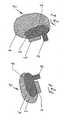
- FIG. 1 While in the FIG. 1 an arrangement as an airbag 1 arranged in the seat cheek is shown in FIG. 2 a arranged in the seat back cheek airbag 1 is shown.
- FIG. 3 A schematic representation of the safety devices in normal operation is in the FIG. 3 represented in which the respective airbags 1 are arranged in the seat side cheeks.
- the upholstery of the seat back cheek can be biased differently taut in the direction of the vehicle occupant 10.
- a better coupling of the vehicle occupant 10 is effected to the vehicle seat.
- a tear seam 21 is formed on the front, through which the airbag can extend in the direction of travel in an accident.
- the in the FIG. 3 shown comfort function allows filling of the comfort chamber 2, for example, depending on the traversed cornering speeds or due to individual Einstellinate.
- the reversible inflation function can also be used as a preparatory measure for an accident.
- the airbags can exert optimal protection.
- the comfort chamber 2 is emptied again or reset to the comfort serving position. In this respect, the comfort chamber is fully inflated upon activation of the pre-crash sensor.
- the safety device is shown in an activated state in which the gas generators 4 have been activated and the retention chambers 6 have been filled with gas.
- These retention chambers 6 may be part of the comfort chambers 2 or formed separately.
- the electric pumps 3 are driven by an electronic unit, not shown, for. B. depending on the Driving situation, the settings of the driver or the like, the airbag 1 is optionally filled by the comfort chamber 2 with gas from the gas generators 4.
- the seat integrity is unimpaired, so do not tear the seat cushion, builds through the .Fill over the gas generators 4. either in a separate chamber or in the comfort chamber 2, a significantly higher internal pressure than by the pump 3.
- the separation of the comfort chamber 2 is lifted from the retention chamber 6 and filled the large volume of the retention chamber 6 for the retention function. Due to the large volume, an opening of the seat is brought about to position the retention chamber 6 outside the seats for the occupant 10.
- the retention chambers 6 lie down next to the vehicle occupants 10.
- FIG. 5 An unclaimed arrangement without exiting the seat cushions is in the FIG. 5 represented in which the safety device is arranged in the seat ramp. While only the comfort chamber 2 is filled or emptied by the pump 3 for the comfort function in order to realize an adaptation of the seat ramp contour to the comfort requirements of the occupant 10 with respect to the thigh support, the retention volume 6 is filled by the activation of the gas generator 4, to a deformation to achieve the seat in such a way that a steep and stiff seat ramp is provided. This avoids the effect that the vehicle occupant 10 slips under a lap belt. Such an effect is called submarining.
- the safety system After filling the retention chambers 6, the safety system operates like a conventional airbag. Via a Veritilationsö réelle a required energy absorption can be provided.
- the safety device saves costs, space and weight compared to separate systems. In addition, one is less effort in terms of control and installation of utilities feasible, so that the savings in terms of cost, space and weight can take place while maintaining the function. After the accident has been detected, individual or all safety devices within the vehicle seat can be activated.
Landscapes
- Engineering & Computer Science (AREA)
- Mechanical Engineering (AREA)
- Aviation & Aerospace Engineering (AREA)
- Transportation (AREA)
- Air Bags (AREA)
- Seats For Vehicles (AREA)
- Electrical Discharge Machining, Electrochemical Machining, And Combined Machining (AREA)
Description
- Die Erfindung betrifft eine Sicherheitseinrichtung in einem Kraftfahrzeugsitz mit einem Airbag und einem Gasgenerator, der bei Vorliegen von Sensordaten über einen Unfall oder einen bevorstehenden Unfall aktiviert wird, den Airbag mit Gas befüllt und entfaltet.
- Fahrzeuge der Oberklasse werden zunehmend mit Komfortfunktionen ausgestattet. Ein neues Ausstattungsmerkmal ist die Möglichkeit, in den Sitzwangen kleine Luftkissen in Abhängigkeit von .der Fahrsituation aufzublasen. Somit ist es beispielsweise während der Kurvenfahrt möglich, diejenige Sitzlehnenwange, die dem Kurvenaußenradius zugeordnet ist, bei entsprechenden Kurvenfahrten aufzublasen, um eine bessere Anbindung des Sitznutzers an den Sitz bereitzustellen. Darüber hinaus können die Luftkissen zur Erhöhung des Sitzkomforts und zur Anpassung der Sitzkontur an den Sitznutzer ausgebildet sein.
- Aus dem Dokument
EP 1 077 154 A2 ist ein Kraftfahrzeugsitz bekannt der eine Sicherheitseinrichtung entsprechend der Präambel des Anspruchs 1 zeigt. Hierbei liegt der Gedanke zugrunde die Verformungsstabilität des Sitzpolsters bei einem Unfall schneller erhöhen zu können, als bei einer Anpassung der gewünschten Nachgiebigkeit im Normalbetrieb. - Darüber hinaus sind in Fahrzeugsitzen Seitenairbags integriert, die bei einem Seitenaufprall oder bei einem drohenden Seitenaufprall aktiviert werden, um sich zwischen einem Sitznutzer und einer Fahrzeugstruktur zu erstrecken.
Aus derEP 1 140 572 B1 ist ein Kraftfahrzeugsitz mit einem gepolsterten Sitzteil bekannt, dessen Sitzfläche mit Seitenwangen ausgestattet ist. Eine gepolsterte Rückenlehrie weist ebenfalls Seitenwangen auf. In Bereichen einer Polsterung des Fahrzeugsitzes sind Hohlräume vorgesehen, die mit einer aktivierbaren Füllvorrichtung in Verbindung stehen. Innerhalb der Seitenwangen sind aufblasbare Luftsäcke angeordnet, die im aufgeblasenen Zustand in der Seitenwange eingeschlossen bleiben. Unterhalb oder innerhalb des Sitzes ist ein Gasgenerator angeordnet, der mit dem jeweiligen Luftsack verbunden ist. - Dabei wird der Gassack innerhalb des Bezugsstoffes bei einem Unfall aufgeblasen und schützt den Sitznutzer vor Verletzungen durch intrudierende Gegenstände. Dem liegt der Gedanke zugrunde, dass die Lage- und Verformungsstabilität eines zum Abbremsen und Festhalten des Fahrzeuginsassen sowie zum Schutz vor intrudierenden Teilen verwendeten Luftpolsters dadurch verbessert wird, dass anstelle eines sich frei entfaltenden Airbags eine oder beide Sitzwangen prall aufgeblasen werden, so dass sich der Überstand über den Mittelteil des Sitzpolsters oder der Rückenlehne vergrößert. Durch das innerhalb der Seitenwangen erzeugte, verhältnismäßig lagestabile Luftkissen kann ein auf dem Sitz sitzender Fahrzeuginsasse stabilisiert und geschützt werden. Durch diese bei einem Unfall zu aktivierende Sicherheitseinrichtung kann eine einmalige Stabilisierung des Sitznutzers gewährleistet werden. Der in den Sitzwangen vorhandene Bauraum ist jedoch dann für Komfortluftkissen belegt.
- Aufgabe der vorliegenden Erfindung ist es, eine Sicherheitseinrichtung in einem Kraftfahrzeug bereitzustellen, die auch die Möglichkeit bietet, den Fahrzeugsitz während des Normalbetriebes des Fahrzeuges an die Bedürfnisse des Sitznutzers anzupassen.
- Erfindungsgemäß wird eine solche Aufgabe durch eine Sicherheitseinrichtung mit den Merkmalen des Anspruchs 1 gelöst. Vorteilhafte Ausgestaltungen und Weiterbildungen der Erfindung werden in den Unteransprüchen beschrieben.
- Die erfindungsgemäße Sicherheitseinrichtung in einem Kraftfahrzeug mit einem Airbag und einen Gasgenerator, der bei Vorliegen von Sensoren über einen Unfall oder einen bevorstehenden Unfall aktiviert wird, den Airbag mit Gas befüllt und entfaltet, ist dadurch gekennzeichnet, dass der Airbag zusätzlich mit einem regulierbaren, ein Volumen des Airbags wiederholt reversibel mit Gas befüllbaren Aktivator gekoppelt ist. Dabei ist es vorgesehen, dass eine Airbagkammer mit einem relativ kleinen Volumen für die Komfortfunktionen in der jeweiligen Sitzwange ungefaltet eingebaut wird. Diese Airbagkammer wird für die jeweils gewünschte Komfortfunktion über den Aktivator wiederholt und reversibel mit Gas befüllt bzw. entleert. Zusätzlich ist der Airbag unmittelbar oder über ein Gasleitsystem mit dem Gasgenerator verbunden, der im Falle eines Unfalles den Airbag mit einer entsprechend großen Gasmenge befüllt, um eine Rückhalte- oder Schutzfunktion auszuüben. Alternativ zu einer Anordnung in einer Sitzlehnenwange oder in einer Sitzflächenwange ist es vorgesehen, dass der Airbag in der Sitzrampe im Bereich einer Knieauflage des Sitzpolsters angeordnet ist, um die Oberschenkelauflage variabel einzustellen und gleichzeitig den sogenannten Submarining-Effekt im Falle eines Unfalles zu unterbinden.
- Eine Weiterbildung der Erfindung sieht vor, dass der Aktivator als eine elektrische Pumpe ausgebildet ist, die sowohl Befüllen als auch Entlüften kann. Alternativ kann zum Entlüften ein Stellventil vorgesehen sein, das zum Reduzieren des Volumens des Airbags geöffnet wird.
- Der Airbag bildet zwei Kammern aus, die unterschiedliche Volumina aufweisen. Die beiden Kammern können voneinander durch eine Reißnaht, eine Verklebung oder eine Faltung und Fixierung voneinander getrennt sein. Die zweite oder weitere Kammer kann durch verschiedene konstruktive Merkmale von dem Bereich des Airbags getrennt werden, der für die Komfortfunktion zuständig ist. Weiterhin kann die zweite Kammer oder das zusätzliche Volumen, das nur im Falle eines Unfalles durch den Gasgenerator befüllt wird, auf den reversibel befüllbaren Airbag für die Komfortfunktion, aufgerollt oder aufgefaltet werden.
- Alternativ dazu ist es möglich, dass die mit dem Aktivator gekoppelte Kammer in der größeren Kammer des Airbags angeordnet ist und eine Kammer innerhalb der Kammer ausbildet. Die Kammer für die Komfortfunktion kann dann mit einer Reißnaht versehen sein, wenn sie ebenfalls über den Gasgenerator oder ein gemeinsames Gasleistsystem mit einem. Gas befüllt wird und das größere Kammervolumen strömungstechnisch mit dem Gasgenerator verbinden.
- Zur Realisierung der Sicherheitsfunktion als Seitenairbag ist es möglich, dass in dem Sitz eine Sollreißnaht zur leichteren Entfaltung des Airbags bei einem Unfall und bei einer Befüllung durch den Gasgenerator ausgebildet ist.
- Der Gasgenerator ist dabei so ausgebildet, dass er einen höheren Airbaginnendruck als der Aktivator bzw. als die Pumpe bereitstellt. Der Gasgenerator und der Aktivator können über ein gemeinsames Gasleitsystem mit dem Airbag gekoppelt sein. Neben einer gemeinsamen Gasführung durch die reversibel befüllbare Kammer ist es vorgesehen, dass der Gasgenerator strömungstechnisch getrennt mit einer weiteren Kammer verbunden ist, die größer als die mit dem Aktivator verbundene Kammer ist, so dass unterschiedliche Gasführungswege verwirklicht werden können.
- Nachfolgend werden Ausführungsbeispiele der Erfindung anhand der beigefügten Figuren näher.erläutert. Es zeigen:
- Figur 1 -
- eine schematische Darstellung eines in einer Sitzfläche angeordneten Airbags;
- Figur 2-
- eine schematische Darstellung eines Seitenairbags;
- Figur 3 -
- eine schematische .Darstellung der Sicherheitseinrichtung im Normalbetrieb;
- Figur 4 -
- eine schematische Darstellung der Sicherheitseinrichtung bei einem Unfall; sowie
- Figur 5 -
- eine nicht beanspruchte Sicherheitseinrichtung in eingebautem Zustand in der Sitzrampe.
-
Figur 1 zeigt einen Airbag 1 mit einer ersten Kammer 2, die über einen Aktivator 3, der als elektrische Pumpe ausgebildet ist, mit einem Gas, insbesondere Luft, befüllt werden kann. Zwischen der Pumpe 3 und der ersten Kammer 2, die auch als Komfortkammer bezeichnet werden kann, ist eine unmittelbare strömungstechnische Verbindung vorhanden. Die Komfortkammer 3 wird für die Komfortfunktionen mit der elektrischen Pumpe 3 befüllt oder entleert. Alternativ zu einer Entleerung über die Pumpe 3 kann dies auch durch ein Ventil geschehen, das geöffnet wird, um Luft auf der Kammer 2 abzulassen. Darüber hinaus ist in der dargestellten Ausführungsform die Kammer 2 direkt mit einem Gasgenerator 4 verbunden, der bei Vorliegen entsprechender Sensordaten, die einen Unfall oder einen bevorstehenden Unfall anzeigen, aktiviert wird. Nach Aktivierung des Gasgenerators 4 wird heißes Gas in die erste oder Komfortkammer 2 geleitet und erzeugt dort einen Innendruck, der eine Reißnaht 5, die in dem Kammergewebe ausgebildet ist, zerreißt. Dadurch wird eine strömungstechnische Verbindung zu einer zweiten Kammer 6 oder Rückhaltekammer hergestellt, die durch die Gase des Gasgenerators 4 befüllt wird. Die Rückhaltekammer 6 ist größer als die Komfortkammer 2 und kann durch verschiedene konstruktive Merkmale von der Komfortkammer 2 getrennt sein. Neben der Reißnaht 5 kann eine Verklebung, eine entsprechende Faltung und Fixierung des umgefalteten Gewebes der Rückhaltekammer 6 und Aufhebung der Fixierung bei Überschreiten eines Kammerinnendruckes realisiert werden. Alternativ dazu kann die Rückhaltekammer 6 auch separat ausgebildet und getrennt von der Komfortkammer 2 mit dem Gasgenerator 4 in Verbindung stehen. Dabei ist es vorgesehen, dass die Komfortkammer 2 als eine in der Rückhaltekammer 6 angeordnete, separate Kammer 2 ausgebildet ist. Die Rückhaltekammer 6 ist dabei als eine Umhüllung für die Komfortkammer 2 ausgebildet und wird bei einem Aufblasen und Ablassen von Luft aus der Komfortkammer 2 entsprechend verlagert. Die aufgrund des angestrebten größeren Volumens der Rückhaltekammer 6 notwendige größere Stofffläche wird durch eine mehrfache Legung oder Auffaltung auf die Komfortkammer 2 platzsparend untergebracht. Alternativ dazu kann der Airbag 1 auch als ein großvolumiger Airbag ausgebildet sein, dessen kleines Volumen zur Ausbildung der Komfortkammer 4 durch eine Trennnaht abgetrennt wird. - Das Prinzip der mehreren Kammern und der sowohl reversibel als auch irreversibel durchzuführenden Befüllung der jeweiligen Kammer kann für unterschiedliche Zonen an einem Sitz verwendet werden. Mögliche Einbaupositionen sind dabei die Sitzlehnenwange, die Sitzrampe oder eine Sitzflächenwange. Im Falle der Rückhaltefunktion entsteht, eine Öffnung des Sitzes im Bereich des Airbags 1, um ein möglichst großes Volumen des Airbags 1 zu ermöglichen. Dies wird mit einer Reißnaht im Sitz erreicht, so dass sich der maximal entfaltete Airbag 1 unmittelbar an den Sitznutzer anlegen kann.
- Während in der
Figur 1 eine Anordnung als ein in der Sitzflächenwange angeordneter Airbag 1 gezeigt ist, ist in derFigur 2 ein in der Sitzlehnenwange angeordneter Airbag 1 dargestellt. - Eine schematische Darstellung der Sicherheitseinrichtungen im Normalbetrieb ist in der
Figur 3 dargestellt, bei der in den Sitzseitenwangen die jeweiligen Airbags 1 angeordnet sind. Durch die jeweiligen Aktivatoren 3 oder Pumpen können die Polster der Sitzlehnenwange unterschiedlich straff in Richtung auf den Fahrzeuginsassen 10 vorgespannt werden. Dadurch wird eine bessere Kopplung des Fahrzeuginsassen 10 an den Fahrzeugsitz bewirkt. Innerhalb der Sitzlehne 20 ist an der Vorderseite eine Reißnaht 21 ausgebildet, durch die sich bei einem Unfall der Airbag in Fahrtrichtung erstrecken kann. Die in derFigur 3 dargestellte Komfortfunktion ermöglicht ein Befüllen der Komfortkammer 2, beispielsweise in Abhängigkeit von den durchfahrenen Kurvengeschwindigkeiten oder aufgrund individueller Einstellwünsche. - Bei Vorhandensein eines Pre-crash Sensors kann die reversible Aufblasfunktion auch als vorbereitende Maßnahme für einen Unfall genutzt werden. Durch die Kopplung des Insassen in den Sitz wird er in eine ideale Position gebracht, so dass bei einem tatsächlichen Unfall die Airbags eine optimale Schutzfunktion ausüben können. Sollte es doch zu keinem Unfall kommen, wird die Komfortkammer 2 wieder entleert bzw. auf die dem Komfort dienende Position zurückgestellt. Insofern wird bei Aktivierung des Pre-crash Sensors die Komfortkammer vollständig aufgeblasen.
- In der
Figur 4 ist die Sicherheitseinrichtung in einem aktivierten Zustand gezeigt, bei der die Gasgeneratoren 4 aktiviert wurden und die Rückhaltekammern 6 mit Gas befüllt wurden. Diese Rückhaltekammern 6 können Teil der Komfortkammern 2 oder separat ausgebildet sein. Während im Komfortmodus die elektrischen Pumpen 3 von einer nicht dargestellten Elektronikeinheit angesteuert werden, z. B. in Abhängigkeit von der Fahrsituation, den Einstellungen vom Fahrer oder dergleichen, wird der Airbag 1 gegebenenfalls durch die Komfortkammer 2 mit Gas aus den Gasgeneratoren 4 befüllt. Während in der Komfortfunktion die Sitzintegrität unbeeinträchtigt ist, also die Sitzpolster nicht zerreißen, baut sich durch die .Befüllung über die Gasgeneratoren 4. entweder in einer separaten Kammer oder in der Komfortkammer 2 ein deutlich höherer Innendruck als durch die Pumpen 3 auf. Dadurch wird die Trennung der Komfortkammer 2 von der Rückhaltekammer 6 aufgehoben und das große Volumen der Rückhaltekammer 6 für die Rückhaltefunktion befüllt. Durch das große Volumen wird eine Öffnung des Sitzes herbeigeführt, um die Rückhaltekammer 6 außerhalb der Sitze für den Insassen 10 zu positionieren. Die Rückhaltekammern 6 legen sich dabei neben den Fahrzeuginsassen 10. - Eine nicht beanspruchte Anordnung ohne Austreten aus den Sitzpolstern ist in der
Figur 5 dargestellt, bei der die Sicherheitseinrichtung in der Sitzrampe angeordnet ist. Während für die Komfortfunktion lediglich die Komfortkammer 2 durch die Pumpe 3 befüllt oder entleert wird, um eine Anpassung der Sitzrampenkontur an die Komfortwünsche des Insassen 10 bezüglich der Oberschenkelauflage zu realisieren, wird durch die Aktivierung des Gasgenerators 4. das Rückhaltevolumen 6 befüllt, um eine Verformung der Sitzfläche dahingehend zu erreichen, dass eine steile und steife Sitzrampe bereitgestellt wird. Dadurch wird der Effekt vermieden, dass der Fahrzeuginsasse 10 unter einem Beckengurt hindurchrutscht. Ein solcher Effekt wird als Submarining bezeichnet. - Nach der Befüllung der Rückhaltekammern 6 arbeitet das Sicherheitssystem wie ein konventioneller Airbag. Über eine Veritilationsöffnung kann eine benötigte Energieabsorption bereitgestellt werden.
- Durch die Sicherheitseinrichtung können Kosten, Bauraum und Gewicht im Vergleich zu getrennten Systemen eingespart werden. Darüber hinaus ist ein geringerer Aufwand bezüglich der Steuerung und Verlegung von Versorgungseinrichtungen realisierbar, so dass die Einsparungen bezüglich Kosten, Bauraum und Gewicht bei Beibehaltung der Funktion stattfinden können. Ja nach detektiertem Unfall können einzelne oder sämtliche Sicherheitseinrichtungen innerhalb des Fahrzeugsitzes aktiviert werden.
Claims (9)
- Sicherheitseinrichtung in einem Kraftfahrzeugsitz mit einem Airbag (1) und einem Gasgenerator (4), der bei Vorliegen von Sensordaten über einen Unfall oder einen bevorstehenden Unfall aktiviert wird und den Airbag (1) mit Gas befüllt, wobei der Airbag (1) zusätzlich mit einem regulierbaren, ein Volumen des Airbags (1) wiederholt reversibel mit Gas befüllbaren Aktivator (3) gekoppelt ist, dadurch gekennzeichnet, dass der Airbag (1) zwei Kammern (2, 6) ausbildet, die unterschiedliche Volumina aufweisen, wobei die Befüllung durch den Aktivator (3) die Sitzintegrität nicht beeinflusst, während durch die Befüllung durch den Gasgenerator der Sitz über eine Reißnaht geöffnet wird, so dass sich der Airbag (1) entfaltet und unmittelbar an den Insassen anlegen kann.
- Sicherheitseinrichtung nach Anspruch 1, dadurch gekennzeichnet, dass der Aktivator (3) als elektrische Pumpe ausgebildet ist.
- Sicherheitseinrichtung nach Anspruch 1 oder 2, dadurch gekennzeichnet, dass die Kammern (2. 6) voneinander durch eine Reißnaht (21), Verklebung oder eine Falzung und Fixierung des Airbags (1) getrennt sind.
- Sicherheitseinrichtung nach einem der voranstehenden Ansprüche, Dadurch gekennzeichnet, dass eine Kammer (2) in der anderen Kammer (6) angeordnet ist.
- Sicherheitseinrichtung nach einem der voranstehende Ansprüche, dadurch gekennzeichnet, dass der Airbag (1) in einer Sitzlehnenwange, Sitzrampe oder Sitzflächenwange angeordnet ist.
- Sicherheitseinrichtung nach einem der voranstehenden Ansprüche, dadurch gekennzeichnet, dass in dem Sitz eine Sollreißnaht zur leichteren Entfaltung des Airbags (1) ausgebildet ist.
- Sicherheitseinrichtung nach einem der voranstehenden Ansprüche, dadurch gekennzeichnet, dass der Gasgenerator (4) einen höheren Airbaginnendruck bereitstellt als der Aktivator (3).
- Siclierheitseinrichtung nach einem der voranstehenden Ansprüche, dadurch gekennzeichnet, dass der Gasgenerator (4) und Aktivator (3) über ein gemeinsames Gasleitsystem mit dem Airbag (1) gekoppelt sind.
- Sicherheitseinrichtung nach einem der Ansprüche 1 bis 7, dadurch gekenntzeichnet, dass der Aktivator (3) strömungstechnisch mit einer Kammer (2) verbunden ist, die kleiner als die Kammer (6) ist, mit der der Gasgenerator (4) verbunden ist und dass der Aktivator (3) und der Gasgenerator (4) strömungstechnisch getrennt mit den jeweiligen Kalmern (2, 6) verbunden sind.
Applications Claiming Priority (2)
| Application Number | Priority Date | Filing Date | Title |
|---|---|---|---|
| DE102005059997A DE102005059997B4 (de) | 2005-12-13 | 2005-12-13 | Sicherheitseinrichtung |
| PCT/EP2006/010995 WO2007068321A1 (de) | 2005-12-13 | 2006-11-16 | Sicherheitseinrichtung |
Publications (2)
| Publication Number | Publication Date |
|---|---|
| EP1963144A1 EP1963144A1 (de) | 2008-09-03 |
| EP1963144B1 true EP1963144B1 (de) | 2009-04-29 |
Family
ID=37667433
Family Applications (1)
| Application Number | Title | Priority Date | Filing Date |
|---|---|---|---|
| EP06818583A Active EP1963144B1 (de) | 2005-12-13 | 2006-11-16 | Sicherheitseinrichtung |
Country Status (5)
| Country | Link |
|---|---|
| EP (1) | EP1963144B1 (de) |
| JP (1) | JP4971352B2 (de) |
| AT (1) | ATE430069T1 (de) |
| DE (2) | DE102005059997B4 (de) |
| WO (1) | WO2007068321A1 (de) |
Families Citing this family (20)
| Publication number | Priority date | Publication date | Assignee | Title |
|---|---|---|---|---|
| JP2008007036A (ja) * | 2006-06-30 | 2008-01-17 | Toyoda Gosei Co Ltd | 乗員保護装置 |
| ATE543693T1 (de) | 2007-03-15 | 2012-02-15 | Takata Petri Ag | Fahrzeugsitzanordnung und verfahren zum schützen eines fahrzeuginsassen |
| DE102007044824B4 (de) | 2007-09-20 | 2019-07-04 | Autoliv Development Ab | Sicherheitseinrichtung für einen Kraftfahrzeugsitz und Kraftfahrzeugsitz |
| DE102007045550A1 (de) * | 2007-09-24 | 2009-04-02 | Autoliv Development Ab | Kraftfahrzeugsitz |
| DE102007045549A1 (de) * | 2007-09-24 | 2009-04-02 | Autoliv Development Ab | Kraftfahrzeugsitz sowie Sicherheitseinrichtung für einen Kraftfahrzeugsitz |
| DE102007045552A1 (de) | 2007-09-24 | 2009-04-02 | Autoliv Development Ab | Kraftfahrzeugsitz mit Sicherheitseinrichtung |
| DE102008005272A1 (de) * | 2008-01-19 | 2009-07-23 | Autoliv Development Ab | Sicherheitseinrichtung für ein Fahrzeug und Verfahren zur Steuerung einer Sicherheitseinrichtung |
| DE102008032981B4 (de) * | 2008-07-07 | 2014-02-13 | TAKATA Aktiengesellschaft | Fahrzeugsitzanordnung |
| CN102099227B (zh) | 2008-07-15 | 2014-04-16 | 高田-彼得里公开股份有限公司 | 机动车辆的车辆座椅设备和气囊设备及保护车辆乘员的方法 |
| EP2319734B1 (de) | 2009-11-04 | 2014-10-22 | Autoliv Development AB | Sicherheitsanordnung |
| DE102010031261A1 (de) * | 2010-07-12 | 2012-01-12 | Robert Bosch Gmbh | Verfahren und Vorrichtung zum Schutz eines Fahrzeuginsassen bei einem Aufprall |
| US8702120B2 (en) * | 2012-06-27 | 2014-04-22 | Ford Global Technologies, Llc | Active bolster deployed from vehicle seat |
| DE102013103802A1 (de) * | 2013-04-16 | 2014-10-16 | Jens FELLER | Gassack-Kraftfahrzeug-Sitz für Kraftfahrzeuge |
| US9457751B1 (en) * | 2015-03-31 | 2016-10-04 | Ford Global Technologies, Llc | Articulating support in a vehicle seat |
| US9505367B2 (en) * | 2015-03-31 | 2016-11-29 | Ford Global Technologies, Llc | Articulating support in a vehicle seat |
| JP6365589B2 (ja) * | 2016-05-24 | 2018-08-01 | トヨタ自動車株式会社 | 車両用乗員保護装置 |
| JP7191583B2 (ja) * | 2017-12-07 | 2022-12-19 | 株式会社豊田中央研究所 | 乗員姿勢制御装置及び乗員姿勢制御方法 |
| JP7590106B2 (ja) * | 2018-10-04 | 2024-11-26 | トヨタ自動車株式会社 | 車両用シート構造 |
| CN110654283A (zh) * | 2019-10-15 | 2020-01-07 | 江苏理工学院 | 一种可智能调节汽车座椅 |
| DE102023002784B4 (de) | 2023-07-07 | 2025-08-28 | Mercedes-Benz Group AG | Fahrzeugsitz mit Anti-Schleuder-Stützvorrichtung |
Family Cites Families (10)
| Publication number | Priority date | Publication date | Assignee | Title |
|---|---|---|---|---|
| DE4320147B4 (de) * | 1992-06-30 | 2006-06-29 | Volkswagen Ag | Sicherheitsvorrichtung für einen Fahrzeuginsassen mit einem Seitenairbag |
| DE29504287U1 (de) * | 1995-03-13 | 1995-05-11 | Bonke, Christoph, Dr., 83126 Flintsbach | Individuell anpaßbare Kopfstütze für Sitze mit Rückenlehne |
| DE19735915B4 (de) * | 1996-08-27 | 2007-06-14 | Volkswagen Ag | Sicherheitseinrichtung für ein Fahrzeug |
| JP2000142321A (ja) * | 1998-11-09 | 2000-05-23 | Fujitsu Ten Ltd | 乗員保護支援装置 |
| DE19938698A1 (de) * | 1999-08-14 | 2001-02-15 | Volkswagen Ag | Fahrzeugsitz |
| DE10022434A1 (de) * | 2000-05-09 | 2001-11-22 | Daimler Chrysler Ag | Verfahren zur fahrdynamischen Adaption der Körperabstützung eines Sitzenden in einem Fahrzeugsitz und Fahrzeugsitz hierzu |
| DE20100155U1 (de) * | 2001-01-05 | 2001-05-10 | TRW Occupant Restraint Systems GmbH & Co. KG, 73553 Alfdorf | Fahrzeugsitz |
| DE10233967A1 (de) * | 2002-07-25 | 2004-02-12 | Manfred Vogt | Kinderrückhaltesystem |
| DE10344587A1 (de) * | 2003-09-25 | 2005-04-28 | Bosch Gmbh Robert | Vorrichtung und Verfahren zur Steuerung und/oder Regelung eines Druckniveaus |
| DE20316865U1 (de) * | 2003-10-30 | 2004-02-12 | Takata-Petri Ag | Sicherheitsvorrichtung für einen Kraftfahrzeugsitz |
-
2005
- 2005-12-13 DE DE102005059997A patent/DE102005059997B4/de not_active Expired - Fee Related
-
2006
- 2006-11-16 AT AT06818583T patent/ATE430069T1/de not_active IP Right Cessation
- 2006-11-16 DE DE502006003639T patent/DE502006003639D1/de active Active
- 2006-11-16 EP EP06818583A patent/EP1963144B1/de active Active
- 2006-11-16 WO PCT/EP2006/010995 patent/WO2007068321A1/de not_active Ceased
- 2006-11-16 JP JP2008544784A patent/JP4971352B2/ja not_active Expired - Fee Related
Also Published As
| Publication number | Publication date |
|---|---|
| ATE430069T1 (de) | 2009-05-15 |
| WO2007068321A1 (de) | 2007-06-21 |
| DE102005059997B4 (de) | 2009-01-29 |
| DE502006003639D1 (de) | 2009-06-10 |
| JP4971352B2 (ja) | 2012-07-11 |
| JP2009519157A (ja) | 2009-05-14 |
| EP1963144A1 (de) | 2008-09-03 |
| DE102005059997A1 (de) | 2007-06-14 |
Similar Documents
| Publication | Publication Date | Title |
|---|---|---|
| EP1963144B1 (de) | Sicherheitseinrichtung | |
| DE102019103484B4 (de) | Fernseitenairbagvorrichtung | |
| DE102008048277B4 (de) | Airbag mit Einsatzklappe | |
| DE69816572T2 (de) | Airbagsystem für Kraftfahrzeuge und Verfahren zur Steuerung dieses Systems | |
| DE102020128218A1 (de) | Fahrzeugsicherheitssystem mit aufblasbarem Gurtrückhalt | |
| EP2714465A1 (de) | Kindersitz mit airbag | |
| DE102011018784B4 (de) | Beifahrerairbag-Vorrichtung | |
| DE112022002443T5 (de) | Sicherheitsgurt-airbag | |
| US9821751B2 (en) | Airbag module | |
| EP1171327A1 (de) | Sicherheitsvorrichtung mit wenigstens einem fondairbag für ein kraftfahrzeug | |
| WO2015120970A1 (de) | Insassenschutzvorrichtung für ein fahrzeug und fahrzeug | |
| DE102012007110A1 (de) | Airbag mit nicht aufgeblasener Tasche | |
| DE112021003626T5 (de) | Bein-rückhalte-airbag | |
| DE102007013105A1 (de) | Insassenschutzeinrichtung für einen Insassen eines Kraftfahrzeugs | |
| DE102016003280A1 (de) | Vorrichtung zum schutz eines insassen eines fahrzeugs | |
| WO2020193359A1 (de) | Rückhaltesystem mit einem sitz und einem in den sitz integrierten gassackmodul sowie verfahren zum betreiben eines rückhaltesystems | |
| DE10137824C2 (de) | Insassenrückhaltesystem im Fondbereich eines Kraftfahrzeugs | |
| DE112018006758T5 (de) | Fahrer-Airbag | |
| DE102015001198B4 (de) | Frontairbagvorrichtung für einen Fahrzeugsitz eines Fahrzeugs | |
| WO2009039954A2 (de) | Kraftfahrzeugsitz mit sicherheitseinrichtung | |
| DE102014017841B4 (de) | Insassenschutzvorrichtung für ein Fahrzeug und Fahrzeug | |
| DE102006005137A1 (de) | Fahrzeugsitz | |
| DE102019112789A1 (de) | Airbagvorrichtung | |
| WO2022238113A1 (de) | Fahrzeug mit einem fahrzeugsitz | |
| DE202021103088U1 (de) | Kinderrückhalteeinrichtung mit Airbag |
Legal Events
| Date | Code | Title | Description |
|---|---|---|---|
| PUAI | Public reference made under article 153(3) epc to a published international application that has entered the european phase |
Free format text: ORIGINAL CODE: 0009012 |
|
| 17P | Request for examination filed |
Effective date: 20080707 |
|
| AK | Designated contracting states |
Kind code of ref document: A1 Designated state(s): AT BE BG CH CY CZ DE DK EE ES FI FR GB GR HU IE IS IT LI LT LU LV MC NL PL PT RO SE SI SK TR |
|
| RIN1 | Information on inventor provided before grant (corrected) |
Inventor name: NARIN, MUHAMMED ALI Inventor name: ZAURITZ, RALF |
|
| GRAP | Despatch of communication of intention to grant a patent |
Free format text: ORIGINAL CODE: EPIDOSNIGR1 |
|
| GRAS | Grant fee paid |
Free format text: ORIGINAL CODE: EPIDOSNIGR3 |
|
| GRAA | (expected) grant |
Free format text: ORIGINAL CODE: 0009210 |
|
| AK | Designated contracting states |
Kind code of ref document: B1 Designated state(s): AT BE BG CH CY CZ DE DK EE ES FI FR GB GR HU IE IS IT LI LT LU LV MC NL PL PT RO SE SI SK TR |
|
| REG | Reference to a national code |
Ref country code: GB Ref legal event code: FG4D Free format text: NOT ENGLISH |
|
| REG | Reference to a national code |
Ref country code: CH Ref legal event code: EP |
|
| REF | Corresponds to: |
Ref document number: 502006003639 Country of ref document: DE Date of ref document: 20090610 Kind code of ref document: P |
|
| REG | Reference to a national code |
Ref country code: IE Ref legal event code: FG4D |
|
| NLV1 | Nl: lapsed or annulled due to failure to fulfill the requirements of art. 29p and 29m of the patents act | ||
| PG25 | Lapsed in a contracting state [announced via postgrant information from national office to epo] |
Ref country code: FI Free format text: LAPSE BECAUSE OF FAILURE TO SUBMIT A TRANSLATION OF THE DESCRIPTION OR TO PAY THE FEE WITHIN THE PRESCRIBED TIME-LIMIT Effective date: 20090429 Ref country code: LT Free format text: LAPSE BECAUSE OF FAILURE TO SUBMIT A TRANSLATION OF THE DESCRIPTION OR TO PAY THE FEE WITHIN THE PRESCRIBED TIME-LIMIT Effective date: 20090429 Ref country code: ES Free format text: LAPSE BECAUSE OF FAILURE TO SUBMIT A TRANSLATION OF THE DESCRIPTION OR TO PAY THE FEE WITHIN THE PRESCRIBED TIME-LIMIT Effective date: 20090809 Ref country code: PT Free format text: LAPSE BECAUSE OF FAILURE TO SUBMIT A TRANSLATION OF THE DESCRIPTION OR TO PAY THE FEE WITHIN THE PRESCRIBED TIME-LIMIT Effective date: 20090829 |
|
| PG25 | Lapsed in a contracting state [announced via postgrant information from national office to epo] |
Ref country code: PL Free format text: LAPSE BECAUSE OF FAILURE TO SUBMIT A TRANSLATION OF THE DESCRIPTION OR TO PAY THE FEE WITHIN THE PRESCRIBED TIME-LIMIT Effective date: 20090429 Ref country code: NL Free format text: LAPSE BECAUSE OF FAILURE TO SUBMIT A TRANSLATION OF THE DESCRIPTION OR TO PAY THE FEE WITHIN THE PRESCRIBED TIME-LIMIT Effective date: 20090429 Ref country code: SE Free format text: LAPSE BECAUSE OF FAILURE TO SUBMIT A TRANSLATION OF THE DESCRIPTION OR TO PAY THE FEE WITHIN THE PRESCRIBED TIME-LIMIT Effective date: 20090729 Ref country code: SI Free format text: LAPSE BECAUSE OF FAILURE TO SUBMIT A TRANSLATION OF THE DESCRIPTION OR TO PAY THE FEE WITHIN THE PRESCRIBED TIME-LIMIT Effective date: 20090429 Ref country code: IS Free format text: LAPSE BECAUSE OF FAILURE TO SUBMIT A TRANSLATION OF THE DESCRIPTION OR TO PAY THE FEE WITHIN THE PRESCRIBED TIME-LIMIT Effective date: 20090829 Ref country code: LV Free format text: LAPSE BECAUSE OF FAILURE TO SUBMIT A TRANSLATION OF THE DESCRIPTION OR TO PAY THE FEE WITHIN THE PRESCRIBED TIME-LIMIT Effective date: 20090429 |
|
| REG | Reference to a national code |
Ref country code: IE Ref legal event code: FD4D |
|
| PG25 | Lapsed in a contracting state [announced via postgrant information from national office to epo] |
Ref country code: IE Free format text: LAPSE BECAUSE OF FAILURE TO SUBMIT A TRANSLATION OF THE DESCRIPTION OR TO PAY THE FEE WITHIN THE PRESCRIBED TIME-LIMIT Effective date: 20090429 Ref country code: RO Free format text: LAPSE BECAUSE OF FAILURE TO SUBMIT A TRANSLATION OF THE DESCRIPTION OR TO PAY THE FEE WITHIN THE PRESCRIBED TIME-LIMIT Effective date: 20090429 Ref country code: CZ Free format text: LAPSE BECAUSE OF FAILURE TO SUBMIT A TRANSLATION OF THE DESCRIPTION OR TO PAY THE FEE WITHIN THE PRESCRIBED TIME-LIMIT Effective date: 20090429 Ref country code: DK Free format text: LAPSE BECAUSE OF FAILURE TO SUBMIT A TRANSLATION OF THE DESCRIPTION OR TO PAY THE FEE WITHIN THE PRESCRIBED TIME-LIMIT Effective date: 20090429 Ref country code: EE Free format text: LAPSE BECAUSE OF FAILURE TO SUBMIT A TRANSLATION OF THE DESCRIPTION OR TO PAY THE FEE WITHIN THE PRESCRIBED TIME-LIMIT Effective date: 20090429 |
|
| PG25 | Lapsed in a contracting state [announced via postgrant information from national office to epo] |
Ref country code: SK Free format text: LAPSE BECAUSE OF FAILURE TO SUBMIT A TRANSLATION OF THE DESCRIPTION OR TO PAY THE FEE WITHIN THE PRESCRIBED TIME-LIMIT Effective date: 20090429 |
|
| PLBE | No opposition filed within time limit |
Free format text: ORIGINAL CODE: 0009261 |
|
| STAA | Information on the status of an ep patent application or granted ep patent |
Free format text: STATUS: NO OPPOSITION FILED WITHIN TIME LIMIT |
|
| PG25 | Lapsed in a contracting state [announced via postgrant information from national office to epo] |
Ref country code: BG Free format text: LAPSE BECAUSE OF FAILURE TO SUBMIT A TRANSLATION OF THE DESCRIPTION OR TO PAY THE FEE WITHIN THE PRESCRIBED TIME-LIMIT Effective date: 20090729 |
|
| 26N | No opposition filed |
Effective date: 20100201 |
|
| BERE | Be: lapsed |
Owner name: AUTOLIV DEVELOPMENT A.B. Effective date: 20091130 |
|
| PG25 | Lapsed in a contracting state [announced via postgrant information from national office to epo] |
Ref country code: MC Free format text: LAPSE BECAUSE OF NON-PAYMENT OF DUE FEES Effective date: 20091130 |
|
| PG25 | Lapsed in a contracting state [announced via postgrant information from national office to epo] |
Ref country code: BE Free format text: LAPSE BECAUSE OF NON-PAYMENT OF DUE FEES Effective date: 20091130 Ref country code: GR Free format text: LAPSE BECAUSE OF FAILURE TO SUBMIT A TRANSLATION OF THE DESCRIPTION OR TO PAY THE FEE WITHIN THE PRESCRIBED TIME-LIMIT Effective date: 20090730 |
|
| PGFP | Annual fee paid to national office [announced via postgrant information from national office to epo] |
Ref country code: GB Payment date: 20100927 Year of fee payment: 5 |
|
| PG25 | Lapsed in a contracting state [announced via postgrant information from national office to epo] |
Ref country code: AT Free format text: LAPSE BECAUSE OF NON-PAYMENT OF DUE FEES Effective date: 20091116 |
|
| PG25 | Lapsed in a contracting state [announced via postgrant information from national office to epo] |
Ref country code: IT Free format text: LAPSE BECAUSE OF FAILURE TO SUBMIT A TRANSLATION OF THE DESCRIPTION OR TO PAY THE FEE WITHIN THE PRESCRIBED TIME-LIMIT Effective date: 20090429 |
|
| PG25 | Lapsed in a contracting state [announced via postgrant information from national office to epo] |
Ref country code: LU Free format text: LAPSE BECAUSE OF NON-PAYMENT OF DUE FEES Effective date: 20091116 |
|
| PG25 | Lapsed in a contracting state [announced via postgrant information from national office to epo] |
Ref country code: HU Free format text: LAPSE BECAUSE OF FAILURE TO SUBMIT A TRANSLATION OF THE DESCRIPTION OR TO PAY THE FEE WITHIN THE PRESCRIBED TIME-LIMIT Effective date: 20091030 |
|
| REG | Reference to a national code |
Ref country code: CH Ref legal event code: PL |
|
| PG25 | Lapsed in a contracting state [announced via postgrant information from national office to epo] |
Ref country code: CH Free format text: LAPSE BECAUSE OF NON-PAYMENT OF DUE FEES Effective date: 20101130 Ref country code: LI Free format text: LAPSE BECAUSE OF NON-PAYMENT OF DUE FEES Effective date: 20101130 |
|
| PG25 | Lapsed in a contracting state [announced via postgrant information from national office to epo] |
Ref country code: TR Free format text: LAPSE BECAUSE OF FAILURE TO SUBMIT A TRANSLATION OF THE DESCRIPTION OR TO PAY THE FEE WITHIN THE PRESCRIBED TIME-LIMIT Effective date: 20090429 |
|
| PG25 | Lapsed in a contracting state [announced via postgrant information from national office to epo] |
Ref country code: CY Free format text: LAPSE BECAUSE OF FAILURE TO SUBMIT A TRANSLATION OF THE DESCRIPTION OR TO PAY THE FEE WITHIN THE PRESCRIBED TIME-LIMIT Effective date: 20090429 |
|
| GBPC | Gb: european patent ceased through non-payment of renewal fee |
Effective date: 20111116 |
|
| PG25 | Lapsed in a contracting state [announced via postgrant information from national office to epo] |
Ref country code: GB Free format text: LAPSE BECAUSE OF NON-PAYMENT OF DUE FEES Effective date: 20111116 |
|
| REG | Reference to a national code |
Ref country code: DE Ref legal event code: R082 Ref document number: 502006003639 Country of ref document: DE Representative=s name: GRAMM, LINS & PARTNER PATENT- UND RECHTSANWAEL, DE |
|
| REG | Reference to a national code |
Ref country code: FR Ref legal event code: PLFP Year of fee payment: 10 |
|
| REG | Reference to a national code |
Ref country code: FR Ref legal event code: PLFP Year of fee payment: 11 |
|
| REG | Reference to a national code |
Ref country code: FR Ref legal event code: PLFP Year of fee payment: 12 |
|
| PGFP | Annual fee paid to national office [announced via postgrant information from national office to epo] |
Ref country code: FR Payment date: 20231123 Year of fee payment: 18 |
|
| PG25 | Lapsed in a contracting state [announced via postgrant information from national office to epo] |
Ref country code: FR Free format text: LAPSE BECAUSE OF NON-PAYMENT OF DUE FEES Effective date: 20241130 |
|
| PGFP | Annual fee paid to national office [announced via postgrant information from national office to epo] |
Ref country code: DE Payment date: 20251126 Year of fee payment: 20 |