EP1964722A1 - Kofferraum eines Kraftfahrzeugs - Google Patents
Kofferraum eines Kraftfahrzeugs Download PDFInfo
- Publication number
- EP1964722A1 EP1964722A1 EP08151960A EP08151960A EP1964722A1 EP 1964722 A1 EP1964722 A1 EP 1964722A1 EP 08151960 A EP08151960 A EP 08151960A EP 08151960 A EP08151960 A EP 08151960A EP 1964722 A1 EP1964722 A1 EP 1964722A1
- Authority
- EP
- European Patent Office
- Prior art keywords
- groove
- floor
- bolt
- shelf
- trunk
- Prior art date
- Legal status (The legal status is an assumption and is not a legal conclusion. Google has not performed a legal analysis and makes no representation as to the accuracy of the status listed.)
- Withdrawn
Links
- 238000005194 fractionation Methods 0.000 abstract 1
- 241001441732 Ostraciidae Species 0.000 description 3
- 230000002093 peripheral effect Effects 0.000 description 2
- 230000014509 gene expression Effects 0.000 description 1
Images


Classifications
-
- B—PERFORMING OPERATIONS; TRANSPORTING
- B60—VEHICLES IN GENERAL
- B60R—VEHICLES, VEHICLE FITTINGS, OR VEHICLE PARTS, NOT OTHERWISE PROVIDED FOR
- B60R5/00—Compartments within vehicle body primarily intended or sufficiently spacious for trunks, suit-cases, or the like
- B60R5/04—Compartments within vehicle body primarily intended or sufficiently spacious for trunks, suit-cases, or the like arranged at rear of vehicle
- B60R5/044—Compartments within vehicle body primarily intended or sufficiently spacious for trunks, suit-cases, or the like arranged at rear of vehicle luggage covering means, e.g. parcel shelves
- B60R5/045—Compartments within vehicle body primarily intended or sufficiently spacious for trunks, suit-cases, or the like arranged at rear of vehicle luggage covering means, e.g. parcel shelves collapsible or transformable
-
- B—PERFORMING OPERATIONS; TRANSPORTING
- B60—VEHICLES IN GENERAL
- B60R—VEHICLES, VEHICLE FITTINGS, OR VEHICLE PARTS, NOT OTHERWISE PROVIDED FOR
- B60R7/00—Stowing or holding appliances inside vehicle primarily intended for personal property smaller than suit-cases, e.g. travelling articles, or maps
- B60R7/02—Stowing or holding appliances inside vehicle primarily intended for personal property smaller than suit-cases, e.g. travelling articles, or maps in separate luggage compartment
Definitions
- the present invention relates to a trunk of a motor vehicle.
- the present invention aims to provide an improved attachment of the trunk shelf.
- the subject of the invention is a box comprising a splitting tablet, a floor comprising at least one locking device making it possible to attach at least one hollow disposed at at least one end of said shelf, characterized in that the floor comprises at least one groove adapted to receive said at least one end of the tablet and in that each locking device comprises a piece forming a bolt movable with respect to the groove adapted to engage in the hollow of said at least one end so as to to block it in all directions.
- the bolt piece is mounted in a recess opening into said at least one groove so that it does not protrude from the floor.
- An insert attached in a groove in the floor forms said at least one groove and said recess.
- Each groove comprises at least one locking device mounted on each side of the vertical plane carried by its direction.
- At least two locking devices are mounted vis-a-vis.
- At least two locking devices are staggered.
- the bolt piece is rotatably mounted relative to the groove.
- the piece forming a bolt is mounted in translation relative to the groove.
- the invention also relates to a motor vehicle comprising a trunk as described above.
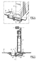
- the rear part of a passenger compartment of a motor vehicle comprises a rear floor 12 and side structure panels 14 right and left (only the left panel is visible in the figure).
- the rear floor 12 and the side structure panels 14 delimit a rear trunk 16 of the vehicle.
- the vehicle further comprises rear seats 18 fixed on the floor 12, in the trunk 16. These rear seats 18 are removable, to promote either the number of people who can take place in the vehicle or a storage volume 20 (the trunk volume 16 not occupied by the rear seats 18).
- the trunk 16 comprises fastening means (not shown) for two rows of three seats each.
- mount up to six seats 18 the storage volume 20 in the trunk 16 is then at its minimum.
- mount no seat the storage volume 20 in the trunk 16 is then at its maximum.
- the split of the trunk 16 between storage volume 20 and rear seats 18 is longitudinal depending on whether the rear seats 18 of one or two rows are mounted, and / or transverse if one or more seats of a row are not mounted.
- the first row of rear seats 18 (the most advanced) is complete, while the second row comprises a single seat 18 disposed on the right of the rear trunk 16.
- the storage volume 20 is constituted by the left rear part of the chest 16.
- the vehicle comprises a removable tray shelf 22 intended to cover the storage space 20 by providing a horizontal wall 22A substantially parallel to the rear floor 12, as well as, if appropriate, if a transverse splitting of the rear trunk 16 is made, a vertical wall 22B, substantially parallel to the structural panels 14.
- the tablet 22 has a generally rectangular shape.
- the shelf 22 is divided by longitudinal parallel joints 24 and transverse 26.
- the expressions “longitudinal” and “transverse” articulations are in relation to the shelf 22.
- the shelf 22 has two longitudinal joints 24 spaced equally in the width of the shelf 22, so as to divide the shelf 22 into three transverse portions (by relative to the general orientation of the vehicle) are equal, as well as three transverse joints 26 dividing the shelf 22 into two longitudinal strips (with respect to the general orientation of the vehicle) central, and two longitudinal strips (with respect to the general orientation of the vehicle), narrower than the central strips, for example five times less narrow.
- the longitudinal joints 24 are constituted by a thinning material of the tablet 22, creating a zone of weakness able to deform elastically.
- Each transverse joint 26 is formed of three hinges 28 aligned but not contiguous. In general, a number of hinges is required corresponding to the number of parts formed by the longitudinal joints 24.
- each transverse joint is interrupted by each longitudinal joint to allow independent movements of the hinge parts relative to each other.
- peripheral strips each define a fastening peripheral edge, respectively, 29A, 29B, opposite to each other.
- the fastener edges 29A, 29B have curved lateral flanges 30A, 30B forming hooks and each defining a recess.
- the lateral flanges and the recesses will be designated hereafter by the same references 30A, 30B.
- the lateral flanges consist of folding of material on the edge of the shelf 22, to fix on the right and / or left the shelf to supports provided longitudinally for this purpose on side panels 14. With reference to the figure 1 , the supports consist for example of longitudinal grooves 31, parallel to this edge 32 of the tablet 22.
- Three hooks are provided on each side (one for each transverse portion of the shelf 22).
- the hooks provided on the horizontal part are referenced 30A, while the hooks provided on the vertical part are referenced 30B.
- indexing grooves 40 of the shelf 22, which may be contiguous, are formed in the floor 12 to receive at the same time each a hook 30B of the vertical portion 22B of the tablet.
- One of the indexing grooves 40 is shown on the figure 2 .
- the three indexing grooves 40 are identical and extend one after the other longitudinally, parallel to the shelf supports of the lateral structure panels 14.
- the three indexing grooves 40 being identical, only one will be described later, with reference to the Figures 2 to 5 .
- the indexing groove 40 has a length and a width equal to or slightly greater respectively than the length and width of a hook 30A or 30B.
- the hook 30B is locked longitudinally and transversely, that is to say in the front-back direction (X axis on the figure 1 ) and in the right-left direction (Y axis on the figure 1 ) with respect to the floor 12.
- the floor 12 further comprises at least one locking device 42 for at least one indexing groove 40.
- the floor 12 comprises three locking devices 42.
- the locking device 42 is of the latch type comprising a movable part 44 constituting the latch bolt.
- the bolt 44 is in the shape of a truncated disc of about one-third.
- the bolt 44 thus comprises an upper surface 46, a circular edge 48 and a straight edge 50 corresponding to the truncation.
- the bolt 44 is disposed in a recess 52 of corresponding shape formed on the floor 12.
- the recess 52 is formed opening into the indexing groove 40.
- the recess 52 has a depth such that the upper surface 46 of the bolt 44 do not protrude from the rest of the floor 12 in particular not to damage the objects deposited on it.
- the bolt 44 is rotatably mounted at its center (the center of the untruncated disc) relative to the floor 12 along a vertical axis XX '.
- This vertical axis XX ' is located so that the truncated edge 50 laterally borders the groove 40 without the bolt 44 encroaching on it. This is the unlocked position of the bolt 44 illustrated on the Figures 2 and 3 .
- Axis XX ' is materialized by a lower pin 51 projecting from the center of the disc, snapped into an orifice 53.
- the bolt 44 is rotatable about the vertical axis XX 'so as to make it take a locking position in which the circular edge 48 projects into the groove 40.
- the bolt 44 also comprises, on its upper surface 46, two depressions 54 arranged symmetrically on either side of the vertical axis of rotation XX ', allowing it to be manually maneuvered.
- the recess 52 and the groove 40 are defined in a single piece 56 attached to the floor 12 and pierced at its center with the orifice 53.
- the insert 56 is inserted by clipping into a single groove. in the floor 12.
- the locking device 42 comprises a latch 60 mounted to move in translation in a guide groove 62, opening perpendicularly into the indexing groove 40.
- the guide groove 62 has a depth such that the bolt 66 of latch 60 does not protrude from the remainder of floor 12.
- Guide groove 62 forms a housing for latch 60.
- the latch 60 comprises a rectangular button 64 and, at the end of the button 64, the bolt 66 directed towards the indexing groove 40.
- the bolt 66 In unlocked position, shown on the figure 6 , the bolt 66 is located at a distance from the indexing groove 40.
- a locking position is obtained by sliding the latch 60 in the guide groove 62, in the direction of the indexing groove 40.
- the bolt 66 In the locking position, the bolt 66 enters the indexing groove 40. Thus, when the hook 30B is received in the indexing groove 40, the bolt 66 engages. In the same way as the first embodiment, the tablet 22 is locked in the vertical direction.
- the guide groove 62 and the indexing groove 40 are preferably defined in an insert, inserted by clipping into a groove of the floor 12.
- the trunk floor comprises only one groove adapted to receive, at the same time, all the hooks 30B of the vertical part of the shelf 22.
- a plurality of locking devices is then arranged on the side of the single groove so as to cooperate each with one of the hooks of the tablet. .
- At least one locking device 42 is provided on each side of the groove 40 in order to be able to lock the shelf 22 as it is folded to the left or right in the trunk 16.
- the distribution of the devices 42 can thus be be substantially symmetrical with respect to the vertical plane carried by the groove 40 or staggered with respect to each other, that is to say offset along the groove 40.
- the invention thus makes it possible to obtain a simple and effective system for fixing the vertical part of a folding trunk shelf.
Landscapes
- Engineering & Computer Science (AREA)
- Mechanical Engineering (AREA)
- Vehicle Step Arrangements And Article Storage (AREA)
Applications Claiming Priority (1)
| Application Number | Priority Date | Filing Date | Title |
|---|---|---|---|
| FR0753620A FR2913223B1 (fr) | 2007-03-02 | 2007-03-02 | Coffre de vehicule automobile. |
Publications (1)
| Publication Number | Publication Date |
|---|---|
| EP1964722A1 true EP1964722A1 (de) | 2008-09-03 |
Family
ID=38577621
Family Applications (1)
| Application Number | Title | Priority Date | Filing Date |
|---|---|---|---|
| EP08151960A Withdrawn EP1964722A1 (de) | 2007-03-02 | 2008-02-26 | Kofferraum eines Kraftfahrzeugs |
Country Status (2)
| Country | Link |
|---|---|
| EP (1) | EP1964722A1 (de) |
| FR (1) | FR2913223B1 (de) |
Citations (4)
| Publication number | Priority date | Publication date | Assignee | Title |
|---|---|---|---|---|
| JPS59190040A (ja) * | 1983-04-12 | 1984-10-27 | Nhk Spring Co Ltd | 荷室等のカバ−装置 |
| EP1180452A2 (de) * | 2000-08-09 | 2002-02-20 | BOS GmbH & Co. KG | Vorrichtung zur Fixierung von formstabilen Koffern in einem Laderaum eines Kraftfahrzeuges |
| FR2861029A1 (fr) | 2003-10-17 | 2005-04-22 | Peugeot Citroen Automobiles Sa | Tablette pliable pour vehicule automobile. |
| US20060022479A1 (en) * | 2004-07-28 | 2006-02-02 | Lear Corporation | Integrated expandable cargo system for vehicles |
-
2007
- 2007-03-02 FR FR0753620A patent/FR2913223B1/fr not_active Expired - Fee Related
-
2008
- 2008-02-26 EP EP08151960A patent/EP1964722A1/de not_active Withdrawn
Patent Citations (4)
| Publication number | Priority date | Publication date | Assignee | Title |
|---|---|---|---|---|
| JPS59190040A (ja) * | 1983-04-12 | 1984-10-27 | Nhk Spring Co Ltd | 荷室等のカバ−装置 |
| EP1180452A2 (de) * | 2000-08-09 | 2002-02-20 | BOS GmbH & Co. KG | Vorrichtung zur Fixierung von formstabilen Koffern in einem Laderaum eines Kraftfahrzeuges |
| FR2861029A1 (fr) | 2003-10-17 | 2005-04-22 | Peugeot Citroen Automobiles Sa | Tablette pliable pour vehicule automobile. |
| US20060022479A1 (en) * | 2004-07-28 | 2006-02-02 | Lear Corporation | Integrated expandable cargo system for vehicles |
Also Published As
| Publication number | Publication date |
|---|---|
| FR2913223A1 (fr) | 2008-09-05 |
| FR2913223B1 (fr) | 2009-06-05 |
Similar Documents
| Publication | Publication Date | Title |
|---|---|---|
| WO2014131964A1 (fr) | Siege pour vehicule automobile comportant un element de dossier avec une partie amovible munie de moyens de rangement | |
| FR3002753A1 (fr) | Vehicule automobile comportant un siege avec un element d'assise amovible pour liberer l'acces a un renfoncement de sa structure interne | |
| EP0869242B1 (de) | Verriegelungsbeschlag für Schiebeflügel | |
| EP1452393B1 (de) | Abnehmbare Hutablage für Fahrzeug und ihre Befestigungsvorrichtung | |
| FR2989407A1 (fr) | Dispositif de commande d'ouverture interieure d'un ouvrant de vehicule. | |
| FR2753663A1 (fr) | Dispositif de montage d'au moins un support d'objets, notamment dans un vehicule automobile | |
| FR3035627A1 (fr) | Dispositif d’arret de charge pivotant a l’interieur de l’habitacle d’un vehicule | |
| FR2918324A1 (fr) | Receptacle, de preference une mallette,une boite, une caisse un panier, une sacoche ou tout element analogue, notamment pour un vehicule. | |
| EP1964722A1 (de) | Kofferraum eines Kraftfahrzeugs | |
| EP4371819A1 (de) | Ausrüstung eines kraftfahrzeugs | |
| EP0724052B1 (de) | Türgriff eines Kraftfahrzeugs zur schnellen Montage durch ein Keil-Nockensystem | |
| FR2565302A1 (fr) | Dispositif d'assujettissement provisoire dans l'espace de deux pieces bord a bord | |
| EP1164676B1 (de) | Vorrichtung zur Befestigung eines elektrischen Geräts auf einem Kabelkanal | |
| FR2999024A1 (fr) | Appareillage electrique et rehausse pour un tel appareillage electrique | |
| EP1160414A1 (de) | Endhalterung für eine Wickelwelle, Verfahren zur Herstellung und Antriebsmechanismus einer Schliess- oder Sonnenschutzeinrichtung mit solcher Vorrichtung | |
| FR3098472A1 (fr) | Ensemble de barres de toit et d’un agencement de coffre d’un véhicule automobile | |
| FR3103155A1 (fr) | Système d’arrimage pour véhicule, accessoire et rail correspondants. | |
| FR2937926A1 (fr) | Support multifonction pour vehicule automobile. | |
| FR2914887A1 (fr) | Vehicule automobile tricorps a surface de charge modulable | |
| FR2796017A1 (fr) | Appui-tete a entraxe modulable et siege comportant un tel appui-tete | |
| FR3137948A1 (fr) | dispositif de fixation | |
| FR3136805A1 (fr) | Rideau de fermeture d’un réceptacle comprenant des éléments rigides articulés | |
| EP1406528B1 (de) | Behälter zum lagern von gegenständen | |
| FR2828156A1 (fr) | Agencement d'une valise dans un coffre de vehicule automobile | |
| EP4596325A1 (de) | Verschlusspaneel für einen kofferraum eines fahrzeugs, das eine verkleidungsplatte umfasst, die eine aufbewahrungs- und haltevorrichtung für einen kleiderbügel umfasst |
Legal Events
| Date | Code | Title | Description |
|---|---|---|---|
| PUAI | Public reference made under article 153(3) epc to a published international application that has entered the european phase |
Free format text: ORIGINAL CODE: 0009012 |
|
| AK | Designated contracting states |
Kind code of ref document: A1 Designated state(s): AT BE BG CH CY CZ DE DK EE ES FI FR GB GR HR HU IE IS IT LI LT LU LV MC MT NL NO PL PT RO SE SI SK TR |
|
| AX | Request for extension of the european patent |
Extension state: AL BA MK RS |
|
| 17P | Request for examination filed |
Effective date: 20090129 |
|
| AKX | Designation fees paid |
Designated state(s): AT BE BG CH CY CZ DE DK EE ES FI FR GB GR HR HU IE IS IT LI LT LU LV MC MT NL NO PL PT RO SE SI SK TR |
|
| GRAP | Despatch of communication of intention to grant a patent |
Free format text: ORIGINAL CODE: EPIDOSNIGR1 |
|
| STAA | Information on the status of an ep patent application or granted ep patent |
Free format text: STATUS: THE APPLICATION IS DEEMED TO BE WITHDRAWN |
|
| 18D | Application deemed to be withdrawn |
Effective date: 20100427 |