EP1969946B1 - Avancement à clip réglable - Google Patents
Avancement à clip réglable Download PDFInfo
- Publication number
- EP1969946B1 EP1969946B1 EP08004493A EP08004493A EP1969946B1 EP 1969946 B1 EP1969946 B1 EP 1969946B1 EP 08004493 A EP08004493 A EP 08004493A EP 08004493 A EP08004493 A EP 08004493A EP 1969946 B1 EP1969946 B1 EP 1969946B1
- Authority
- EP
- European Patent Office
- Prior art keywords
- clip
- drive unit
- strand
- feed
- conveyor apparatus
- Prior art date
- Legal status (The legal status is an assumption and is not a legal conclusion. Google has not performed a legal analysis and makes no representation as to the accuracy of the status listed.)
- Active
Links
Images


Classifications
-
- A—HUMAN NECESSITIES
- A22—BUTCHERING; MEAT TREATMENT; PROCESSING POULTRY OR FISH
- A22C—PROCESSING MEAT, POULTRY, OR FISH
- A22C11/00—Sausage making ; Apparatus for handling or conveying sausage products during manufacture
- A22C11/12—Apparatus for tying sausage skins ; Clipping sausage skins
- A22C11/125—Apparatus for tying sausage skins ; Clipping sausage skins by clipping; Removal of clips
Definitions
- the present invention relates to a clip conveying device for conveying a clip strand consisting of a plurality of clips in a clip machine, in particular a sausage clipper, according to the preamble of claim 1.
- the invention relates to a clip conveying device for conveying a closure clip or clip strand consisting of a plurality of closing clips or clips in a clip machine, in particular a sausage clipper, wherein the clip conveying device comprises a drive unit and a feed or feed mechanism. Has transport element.
- the feed element is coupled with its drive end to the drive unit. It is driven by the drive unit in such a way that its end opposite the drive end describes an elliptical path and engages the gradual conveying of the clip strand in spaces between two clips of the clip strand and this promotes stepwise in the feed direction.
- the sausage meat is fed from a filling machine via a filling tube of a clip machine.
- the clipper the contents in a by a first clip filled on the first sausage end unilaterally closed, tubular packaging casing material and closed by setting a second clip on the second sausage end.
- the packaging casing material of the resulting sausage product is separated from the supply of the remaining packaging casing material and discharged the finished sausage product from the clip machine.
- the clip machine For setting and closing the closing clips or the clip, the clip machine usually has a first closing tool, the die, and a second closing tool, the punch. These are arranged between the mouth opening of the filling tube and the transport device of the clip machine for discharging the finished sausage products.
- the die is below the conveying path of the sausage products and the stamp above this conveying path.
- clips are processed, which are made of an embossed aluminum wire strand.
- the clips are pre-bent in a U-shape and hang together by means of bent at their leg ends webs.
- the thus formed clip strand is fed to the die by a clip conveyor along a guideway, which opens into the region of the associated closing tool.
- the foremost clip is known to be fed by an intermittently engaging advancing element of the die. As long as the foremost clip is still connected to the subsequent strand of the clip, it is stably held by the latter in the die.
- the die When closing, the die is first moved to its closing or stroke end position. In this position, the foremost clip is pressed against the braid of packaging casing material and is clamped between this and the die.
- a clip machine of the type mentioned is known from EP-Offentegungsschrift 1 736 412.
- the clip machine shown there has a closing lever with a first closing tool, the die, which is arranged on the closing lever and pivotable with this.
- a second closing tool, the stamp is arranged to be movable along linear guide means relative to the first closing tool.
- the closure tools are movable for closing clips relative to each other between an open position and a closed position.
- a clip strand is guided in the direction of the die along a guide track beginning near the pivot axis of the closing lever.
- an intermittently acting on the clip strand conveyor in the form of an eccentrically driven lever is arranged at the front end of Verschwinhebels. The conveyor raises the clip strand at its end near the die, pulls it in the direction of the die, thereby inserting the foremost clip of the clip strand into the die.
- the die moves towards the die.
- the first clip is first separated from the following clip strand by means of a shearing device provided on the stamp.
- the front clip is free and is only pressed by the tension of the braid against the die.
- the clip is plastically deformed by a further approach of the punch to the die until the closing tools have approached to the clip height and the clip is closed around the Schlauchzopf around.
- Such known clip conveyor usually have a fixed feed stroke, which is adapted to the clip size. If clips of a different size are to be processed, for example if the calorie of the sausage products changes, it is necessary to adjust the feed length or the feed stroke of the new clip size.
- the known in practice clip conveyor devices have a further disadvantage.
- the clip strand is not locked for a period between the separation of the clip located in the die and the renewed engagement of the feed element in the following gap between two clips of the clip strand in the feed direction. If the clip strand is under tension due to the advancing movement, it can be withdrawn against the advancing direction when the foremost clip is separated from the clip strand in the engagement region of the advancing element, which impedes or prevents a desired engagement.
- Object of the present invention is to provide a clip conveyor for conveying a clip consisting of several clips in a clip machine of the type mentioned above, which is simple and which allows easy adjustment of the feed length and the feed stroke of the clip strand.
- a clip conveyor for conveying a clip consisting of several clips in a clip machine, in particular a sausage clipper, proposed according to the invention which has a drive unit and a feed element, which is coupled with its drive end to the drive unit and the drive unit in the manner is drivable that its end conveyor describes an elliptical path and engages the gradual conveying of the clip strand in spaces between two clips of the clip strand and this promotes stepwise in the feed direction.
- an adjusting device is provided with a pivot axis about which the feed element is pivotable and which is adjustable in its position without tools in such a way that at least one of the two axes, main or minor axis of the feed end of the feed element described elliptical path is changeable.
- the position of the pivot axis of the adjusting device is adjustable by an eccentric.
- the pivot axis is thus adjustable on a circular path, whereby a change in the position position of the pivot axis, a simultaneous adjustment of the feed stroke or the feed length as well as the engagement position of the delivery end of the feed element takes place. This adjustment is advantageous because when changed Clip size next to the feed stroke and the engagement point on the clip strand changes.
- the position of the pivot axis of the adjustment can be adjusted in various ways. If this is done in an advantageous manner from the outside by an actuator, so the adjustment can be done manually.
- the feed element may not be firmly connected to the pivot axis, but must, in order to fulfill the desired function correctly, be slidably guided along the pivot axis.
- the pivot axis of the adjusting device engages in a slot in the feed element. This simple and safe construction ensures the guidance of the feed element.
- the drive unit for the feed element can be formed by various drive elements.
- the drive element is an eccentric.
- the desired elliptical path of the conveying end of the feed element can be particularly easily generated by the use of an eccentric and change in the desired manner.
- the shaft of the drive element rotates about a non-displaceable axis.
- an eccentric of the associated eccentric pin rotates on a fixed in relation to the pivot axis of the adjusting circular path.
- each position of the pivot axis of the adjustment is assigned exactly a certain feed stroke and an associated point of engagement of the delivery end of the feed element.
- the axis of the drive element of the drive unit is additionally adjustable so that at least one of the two axes, main or minor axis, the elliptical path described by the conveying end of the advancing element is variable.
- the circular path of the eccentric pin of the drive element would move accordingly, creating a further adjustment for adjusting the feed stroke and the engagement point of the feed element would be created.
- the feed of the clip strand can occur in this tensile stresses.
- the further provided self-acting retainer which can be brought into engagement with a clip located at the front end of the clip strand, effectively prevents the clip strand from slipping back after the clip located in the die has been separated from the clip strand. In this way, the correct engagement of the feed element in the clip strand is ensured by the thus achieved always the same position of the clip strand.
- the retaining device and the advantageous embodiments explained in more detail below can also be used independently of the setting device described in more detail in a generic clip conveying device, since the possibility of setting the clip conveying device to different clip sizes is independent of the problem. to hold the clip strand in its position after a conveying or advancing step.
- the embodiment of the retaining device can be realized in various ways.
- a particularly advantageous embodiment is achieved in that a recess or second clip pocket is provided on the die next to the first clip of the clip strand when closing fixing the first clip pocket, preferably in the immediately following the foremost clip Clip is held, wherein force applying means for applying a fixing force acting on this clip.
- These force application means can be formed for example by a clip guide which is located on the upper side of the clip line and applies the holding force to the clip located in the second pocket of the die.
- the retaining device is formed by a hook, which, e.g. can be arranged parallel to or below the clip strand. This against the feed direction aligned hooks could be brought out of engagement with the clip strand, for example, by the vertical lifting movement of the clip strand during the feed and engage in the lowering of the clip strand after a successful feed back into this.
- a hook By such a hook, the clip strand is securely fixed and prevented from slipping back against the conveying direction after separation of the clip located in the die.
- the retaining device may also be formed by a hydraulic or pneumatic cylinder.
- the exemplary embodiment of a clip conveying device according to the invention described below is used in, for example, sausage clipper machines of the type mentioned in the introduction.
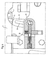
- the clip conveyor 1 as essential components, a drive unit 10, a feed or transport element 20, an adjustment 30 and a retainer 40 on.
- the drive unit 10 which has an eccentric drive element in the illustrated embodiment, is located below the horizontally extending and in a clip guide 4 guided clip strand 2.
- the eccentric is mounted on a rotatably mounted drive shaft 12.
- the eccentric is mounted rotatably and axially fixed so arranged that its eccentric one in the plane of the FIG. 1 describes running circle.
- the eccentric can be set in rotation, for example, by a belt or chain drive, not shown, which is driven by the main machine drive or by the main machine axis. It is also possible that the drive of the eccentric are driven by a likewise not shown hydraulic or pneumatic cylinder or by a turn not shown electric motor. It is usually made of stainless steel.
- the clip guide 4 is formed by a horizontally extending and downwardly open substantially U-shaped profile. In this, the clip strand 2 is held displaceably in the feed direction V and secured against slipping sideways (see. Fig. 1 ).
- the clip guide 4 has a pivot point, not shown, which allows it to be raised together with the clip strand 2 and lowered again when the feed element 20 passes through a feed step explained in more detail below.
- the substantially vertically arranged elongated and lever-like feed element 20 consists of an approximately cuboid flat material whose main plane of extension in the plane of the FIG. 1 lies.
- the feed element 20 is also preferably made of stainless steel. It has at its drive end 22 an eye over which it is axially fixed to the eccentric pin 14 and rotatably connected to the drive unit 10 about its longitudinal axis.
- the conveying end or the conveying tooth 24 of the advancing element 20 is formed by a likewise cuboidal flat material, which, however, is arranged perpendicular to the main extension plane of the advancing element 20.
- a slot 26 is incorporated, which runs centrally on the transport element 20 and in its longitudinal extent.
- the adjustment means 30 consists of a rotatably mounted in the clip lever shaft 32, at its upper end in the illustration, an adjustment member 34 is mounted, by means of which the shaft 32 can be rotated about its longitudinal axis.
- an eccentric 35 is formed on this. It has an axis-parallel to the shaft 32 extending eccentric pin 36 which is aligned in the direction of the feed element 20.
- latching devices in the form of radially arranged bores 38 are further provided, in which an unspecified, spring-loaded locking element 39 engages to fix the selected position of the adjuster 30 and secure against unintentional adjustment (see. Fig. 4 ).
- the adjusting device 30 is arranged in the region of the slot 26 of the advancing element 20 and substantially vertically above the drive unit 10.
- the axis of the shaft 32 of the adjusting device 30 extends horizontally in and perpendicular to the feed direction V.
- the advancing element 20 facing eccentric pin 36 engages the slot 26 and thus forms the pivot axis 36 for the transport element 20.
- the adjustment device 30 is also preferably made of stainless Made of steel.
- actuator 34 Since that in Fig. 2 shown actuator 34 experiences little mechanical stress, it may for example be made of aluminum and about have a correspondingly designed surface to further facilitate manual adjustment of the clip size. As continues in Fig. 2 can be seen, may be provided on the adjusting element 34 a the clip sizes corresponding label.
- the retaining device 40 for the clip strand 2 is formed in the illustrated embodiment, first by a on the die 5 next to the first pocket 5 a, which holds a clip to be closed clip 3 (1st clip of the clip strand), provided second pocket 5 b, which, as this out Fig. 2 can be seen, left of the shearing edge 6 of the die 5 is located. How to continue Fig. 2 can be removed, in this second pocket 5b of the first clip 3 immediately following second clip 3 is arranged. In order for the second clip 3 immediately following the first clip to remain arranged in the second pocket 5b of the die 5, the clip guide 4 continues to extend beyond this second clip 3, as does likewise Fig. 2 is apparent.
- the horizontally extending upper end plate of the clip guide 4 presses on the located in the second pocket 5b of the die 5 clip 3, so that the clip strand is not withdrawn against the feed direction V at Auseingingriffalter the feed element 20.
- the second pocket 5b has the same configuration as the first pocket 5a, ie, their bottom contour curve corresponds to that of a clip 3.
- the leaf spring previously used in the prior art is recognizable, which may optionally be provided in addition.
- the retaining device 40 according to the invention which, as already mentioned above, can be used independently of the adjusting device 30 in a generic clip conveyor, is no longer dependent on this leaf spring. Rather, the second pocket 5b of the die 5 and the clip guide 4 suffices.
- the drive unit 10 rotates in the with A in Fig. 1 marked direction in a clockwise direction about the axis of rotation of the shaft 12.
- the drive end 22 of the feed element 20 describes a in the plane of the Fig. 1 lying circle.
- the conveying end 24 of the advancing element 20 is disengaged from the clip strand 2.
- the feed element 20 is moved due to the guide by the pivot axis 36 in the slot 26 down and pivoted about the pivot axis 36.
- the conveying end 24 of the advancing element 20 upon rotation of the drive unit 10 in a clockwise direction, the conveying end 24 of the advancing element 20 describes an elliptical path in the counterclockwise direction. While the eccentric pin 14 describes the lower half of the circular path about the axis of the rotary shaft 12 of the drive unit 10 starting from the right, the conveying end 24 of the feed element 20 moves on the lower half of the elliptical path from left to right. It gets out of engagement with the clip strand 2 and moves according to the elliptical path down and back up again to intervene, offset by the length of the horizontally extending ellipse axis to the right, in the clip strand 2.
- the die 5 and an unrepresented stamp of the closing tools of the clip machines are moved together to close the inserted in the clip 3, not shown plait packaging wrapper material.
- the clip 3 is sheared off by the interaction of the shearing edge 6 of the die 5 and a corresponding shearing edge of the stamp from the clip strand 2 and pressed around the lying in the clip 3 plait packaging wrapper material, to close this.
- the retaining device 40 prevents the clip strand 2 from slipping backwards counter to the feed direction V by the support of the leg 5 of the clip strand 2 facing the die 5.
- the finished sausage product is transported out of the clip machine.
- the eccentric pin 14 of the drive unit 10 describes in the further course of the production process of a sausage product, the upper half of the circular path.
- the conveying end 24 of the advancing element 20, which is now again in engagement with the clip strand 2 moves on the upper half of the elliptical path of right to left.
- the clip strand 2 is raised together with the clip guide 4 and lowered back into the position shown.
- the clip strand 2 in the guide 4 is displaced to the left by the length of the horizontally extending ellipse axis or by one clip length, and the front clip 3 is moved over the shear edge 6 into the first pocket 5 a of the die 5 and the immediately following second clip 3 in the second pocket 5b of the die 5, which forms the retainer 40 together with the clip guide 4, promoted.
- a clip strand 2 was first inserted into the clip machine for the production process described above, and the adjusting element 34 was turned into the corresponding position corresponding to the size of the inserted clips. If, for example, the caliber of the sausage products to be produced is changed for a further production process, it is usually necessary to use clips of other sizes in addition to other closing tools. Such clips have not only a different leg length, but usually also a different width, so that an adjustment of the clip feed must be made.
- the actuator 34 has a classification corresponding to the selectable clip sizes.
- the desired clip size is adjusted by turning the actuator 34.
- the pivot axis 36 of the feed element 20 is moved on a circular path about the rotational axis of the shaft 32 of the adjusting device 30 (see. Fig. 1 ).
- the pivot axis 36 moves both horizontally and vertically.
- both the feed stroke and the point of engagement of the delivery end 24 of the feed element 20 change
- the horizontal adjustment component causes a shift of the engagement point of the conveying end 24 of the advancing element 20 in the clip strand 2 to the right or left.
- the conveying end 24 of the advancing element 20 describes an ellipse whose main axis also runs through this vertical imaginary line.
- On this line is the point of the highest vertical stroke of the clip strand 2.
- the point of engagement of the conveyor end 24 is in the clip strand 2 and at the same distance to the left of this line is the point at which the conveying end 24 of the advancing member 20 is disengaged from the clip strand 2.
- latching elements may be provided, which are designed in the illustrated embodiment as radially arranged bores 38 in the shaft 32 of the adjusting device 30, in which a spring-loaded locking element 39 engages.
- This securing element 39 is a substantially cylindrical pin which can engage against the tension of a spring 39 a in one of the radial bores 38 in order to prevent unintentional rotation of the shaft 32.
- the spring tension is chosen so that on the one hand prevents rotation of the shaft 32 by the movement of the feed element 20, on the other hand, however, allows an intentional adjustment by manual actuation of the actuating element 34.
- three radial bores are mounted on the shaft 32, for adjusting the clip size setting at three different clip sizes.
- any number of locking positions for the securing element 39 may be provided in order to achieve a corresponding adaptation of the clip size setting to different numbers of clip sizes.
- the invention does not refer to that in the Fig.1 and 2 illustrated embodiment is limited. It is conceivable, for example, for the advancing element 20 to essentially consist of a hollow profile in order, for example, to achieve a reduction in the moved mass, as a result of which vibrations in the clip machine can be reduced.
- the retainer 40 may also be designed as a piston / cylinder assembly, in which case instead of in the Fig. 1 and 2 shown second pocket 5b of the die 5 and the clip guide 4 of the piston is moved hydraulically or pneumatically in the appropriate position. Also can be used instead of hydraulic or pneumatic drives electric drive.
- pivot axis 36 can be adjusted by a linear guide.
- the horizontal and the vertical adjustment component can be weighted differently or one of both completely excluded.
- the locking elements can be designed so that they engage audibly and / or tactually, thereby an accurate adjustment of the desired clip size is facilitated. It can also be provided that the securing element 39 is designed so that it can be actuated from the outside, for example by an actuating element located on the machine. This allows a higher spring tension can be selected for locking and thus a safer locking can be achieved.
Landscapes
- Life Sciences & Earth Sciences (AREA)
- Engineering & Computer Science (AREA)
- Wood Science & Technology (AREA)
- Zoology (AREA)
- Food Science & Technology (AREA)
- Package Closures (AREA)
- Dovetailed Work, And Nailing Machines And Stapling Machines For Wood (AREA)
- Framework For Endless Conveyors (AREA)
Claims (10)
- Dispositif de convoyage de clips pour convoyer une corde de clips (2) se composant d'une pluralité de clips dans une machine de clips, en particulier dans une machine de clips pour saucissons, avec une unité d'actionnement (10) et un élément de transport (20) qui est accouplé avec l'unité d'actionnement (10) par son extrémité d'actionnement (22) et qui peut être actionné par l'unité d'actionnement (10) d'une telle manière que son extrémité de convoyage (24) décrit une trajectoire elliptique et interfère dans des espaces intermédiaries entre deux clips de la corde de clips (2) pour convoyer pas à pas la corde de clips (2) et la convoit pas à pas en direction d'avance (V),
caractérisé en ce qu'il est prévu une installation d'ajustement (30) avec un axe de pivotage (36) autour duquel l'élément de transport (20) est pivotable et lequel est ajustable sans un outil en sa position d'une telle manière qu'au moins un des axes de la trajectoire elliptique décrit par l'extrémité de convoyage (24) est variable. - Dispositif de convoyage de clips selon la revendication 1,
caractérisé en ce que la position de l'axe de pivotage (36) de l'installation d'ajustement (30) est adjustable par un excentrique. - Dispositif de convoyage de clips selon la revendication 1,
caractérisé en ce que la position de l'axe de pivotage (36) de l'installation d'ajustement (30) est adjustable par un guidage linéaire. - Dispositif de convoyage de clips selon une des revendications 1 à 3,
caractérisé en ce que la position de l'axe de pivotage (36) de l'installation d'ajustement (30) est adjustable de l'extérieur par un element de réglage (34). - Dispositif de convoyage de clips selon une des revendications 1 à 4,
caractérisé en ce que l'axe de pivotage (36) de l'installation d'ajustement (30) interfère dans un trou longitudinal (26) dans l'élément de transport (20). - Dispositif de convoyage de clips selon une des revendications 1 à 5,
caractérisé en ce que l'unité d'actionnement (10) contient au moins un excentrique. - Dispositif de convoyage de clips selon une des revendications 1 à 6,
caractérisé en ce que l'unité d'actionnement (10) tourne autour d'un axe fixe (12). - Dispositif de convoyage de clips selon une des revendications 1 à 7,
caractérisé en ce que l'axe (12) de l'unité d'actionnement (10) est ajustable d'une telle manière qu'au moins un des axes, de la trajectoire elliptique décrite par l'extrémité de convoyage (24) de l'élément de transport (20), peut être varié. - Dispositif de convoyage de clips selon une des revendications 1 à 8,
caractérisé en ce qu'il est prévu une installation de retenue (40) operant automatiquement, laquelle peut être mis en interférence avec un clip (3) disposé à l'extrémité antérieure de la corde de clips (2). - Dispositif de convoyage de clips selon la revendication 9,
caractérisé en ce que l'installation de retenue (40) est formée par un creux prévu à une matrice (5) et par un moyen pour appliquer une force, lequel applique une force opérant essentiellement perpendiculaire à la direction d'avance (V) sur la corde de clips (2).
Applications Claiming Priority (1)
| Application Number | Priority Date | Filing Date | Title |
|---|---|---|---|
| DE102007012778A DE102007012778B4 (de) | 2007-03-16 | 2007-03-16 | Einstellbarer Clipvorschub |
Publications (2)
| Publication Number | Publication Date |
|---|---|
| EP1969946A1 EP1969946A1 (fr) | 2008-09-17 |
| EP1969946B1 true EP1969946B1 (fr) | 2011-01-26 |
Family
ID=39577900
Family Applications (1)
| Application Number | Title | Priority Date | Filing Date |
|---|---|---|---|
| EP08004493A Active EP1969946B1 (fr) | 2007-03-16 | 2008-03-11 | Avancement à clip réglable |
Country Status (6)
| Country | Link |
|---|---|
| US (1) | US7926689B2 (fr) |
| EP (1) | EP1969946B1 (fr) |
| BR (1) | BRPI0801513B1 (fr) |
| DE (2) | DE102007012778B4 (fr) |
| ES (1) | ES2356696T3 (fr) |
| RU (1) | RU2399273C2 (fr) |
Families Citing this family (5)
| Publication number | Priority date | Publication date | Assignee | Title |
|---|---|---|---|---|
| ES2576827T3 (es) * | 2010-02-10 | 2016-07-11 | Poly-Clip System Gmbh & Co. Kg | Máquina de grapar de operación manual |
| EP2572585B1 (fr) * | 2011-09-26 | 2016-08-24 | Poly-clip System GmbH & Co. KG | Dispositif de transport avec roues en étoile |
| DE202012004217U1 (de) * | 2012-04-27 | 2013-07-30 | Tipper Tie Technopack Gmbh | Zufuhrvorrichtung für Clipmaschine |
| CN112167303A (zh) * | 2020-10-19 | 2021-01-05 | 石家庄睿普雷健康科技有限公司 | 一种食品封装打卡机 |
| EP4573912A1 (fr) | 2023-12-20 | 2025-06-25 | Sagar Lorenzo Noguera | Machine de fermeture pour fermer des produits de type saucisse |
Family Cites Families (20)
| Publication number | Priority date | Publication date | Assignee | Title |
|---|---|---|---|---|
| US2233839A (en) * | 1938-06-10 | 1941-03-04 | Heurtier Antoine | Moving picture projecting machine |
| US2404875A (en) * | 1944-02-07 | 1946-07-30 | George H Worrall | Kinetograph movement |
| US2420444A (en) * | 1944-08-29 | 1947-05-13 | Vry Corp De | Intermittent mechanism |
| US2506649A (en) * | 1947-02-08 | 1950-05-09 | Arthur E Reeves | Film feed mechanism |
| FR1190749A (fr) * | 1957-01-16 | 1959-10-14 | Werkzeug Und Metallwarenfabrik | Agrafe pour la fermeture étanche à l'air de sacs et dispositif pour l'application desdites agrafes |
| FR1414569A (fr) * | 1964-11-24 | 1965-10-15 | Procédé et dispositif de fermeture continue de saucisses | |
| US3612371A (en) * | 1968-01-20 | 1971-10-12 | Nippon Kogaku Kk | Film transmitting device of miniature movie camera |
| CH481393A (fr) * | 1968-09-27 | 1969-11-15 | Paillard Sa | Mécanisme d'entraînement intermittent d'un film cinématographique |
| FR2123667A5 (fr) * | 1971-01-27 | 1972-09-15 | Eclair Int | |
| US4257328A (en) * | 1979-05-18 | 1981-03-24 | Gavit Stephan E | Strip label printer |
| AT366828B (de) * | 1980-01-04 | 1982-05-10 | Moviecam Kinematograph | Greiferwerk fuer eine filmaufnahmekamera |
| US4357082A (en) * | 1980-12-29 | 1982-11-02 | Amesbury Maurice G | High speed film advancement mechanism and system therefor |
| US4534630A (en) * | 1984-01-31 | 1985-08-13 | Imax Systems Corporation | Wide film transport and register movement |
| US4896960A (en) * | 1988-10-13 | 1990-01-30 | Williamson Geoffry H | High speed transport for large film formats |
| DE10131807C1 (de) * | 2001-06-30 | 2002-11-07 | Poly Clip System Gmbh & Co Kg | Portionierungsvorrichtung |
| CH698066B1 (de) * | 2002-12-11 | 2009-05-15 | Tipper Tie Alpina Ag | Verschliessanordnung für Verschlussclips. |
| DE20314562U1 (de) * | 2003-09-19 | 2003-12-04 | Poly-Clip System Gmbh & Co Kg | Clipmaschinenantrieb |
| DE102004015892B4 (de) * | 2004-03-31 | 2006-02-09 | Poly-Clip System Gmbh & Co. Kg | Verschließmaschinenantrieb mit verstellbarem Anlenkpunkt |
| DE102005029227B4 (de) | 2005-06-23 | 2007-11-08 | Poly-Clip System Gmbh & Co. Kg | Clipmaschine |
| DE102005033437A1 (de) * | 2005-07-18 | 2007-02-01 | Poly-Clip System Gmbh & Co. Kg | System aus einer Clipmaschine und einem Clipvorrat und Verfahren zum Betreiben einer solchen Clipmaschine |
-
2007
- 2007-03-16 DE DE102007012778A patent/DE102007012778B4/de not_active Expired - Fee Related
-
2008
- 2008-03-11 EP EP08004493A patent/EP1969946B1/fr active Active
- 2008-03-11 DE DE502008002438T patent/DE502008002438D1/de active Active
- 2008-03-11 ES ES08004493T patent/ES2356696T3/es active Active
- 2008-03-14 RU RU2008110021/13A patent/RU2399273C2/ru active
- 2008-03-14 US US12/048,643 patent/US7926689B2/en active Active
- 2008-03-17 BR BRPI0801513-9A patent/BRPI0801513B1/pt active IP Right Grant
Also Published As
| Publication number | Publication date |
|---|---|
| US7926689B2 (en) | 2011-04-19 |
| DE102007012778A1 (de) | 2008-09-18 |
| EP1969946A1 (fr) | 2008-09-17 |
| BRPI0801513B1 (pt) | 2017-06-20 |
| BRPI0801513A2 (pt) | 2008-12-16 |
| US20080223694A1 (en) | 2008-09-18 |
| RU2008110021A (ru) | 2009-09-20 |
| ES2356696T3 (es) | 2011-04-12 |
| RU2399273C2 (ru) | 2010-09-20 |
| DE102007012778B4 (de) | 2010-06-24 |
| DE502008002438D1 (de) | 2011-03-10 |
Similar Documents
| Publication | Publication Date | Title |
|---|---|---|
| EP1844659B1 (fr) | Nouage direct d'un dispositif d'agrafe de saucisson et d'alimentation de saucisson | |
| EP1967073B1 (fr) | Réglage d'extension automatique | |
| DE3884944T2 (de) | Verpackungsvorrichtung für den Einsatz von schlauchförmigem Hüllmaterial. | |
| EP1886573B1 (fr) | Machine de fermeture par clip | |
| EP1969945B1 (fr) | Procédé et dispositif de fermeture commandée d'au moins un clip autour d'une section tressée exempte de produit de remplissage entre deux sections tressées fermées par un emballage | |
| DE1461915B2 (de) | Vorrichtung zur Herstellung von Quaderpackungen | |
| EP1969946B1 (fr) | Avancement à clip réglable | |
| EP1736412B2 (fr) | Machine de fermeture par clip | |
| EP2225948B1 (fr) | Dispositif d'entrée pour éléments de suspension | |
| EP0399322A3 (fr) | Appareil de brochage | |
| EP2186415B1 (fr) | Composant de refoulement pour une machine à clips | |
| DE2628322C2 (fr) | ||
| EP0712365B1 (fr) | Dispositif de fermeture d'une attache en plastique en deux parties | |
| EP2103221B1 (fr) | Sections de vis transporteuse | |
| DE102004022716B4 (de) | Vorrichtung zum Herstellen von gefüllten, verschlossenen Schlauchbeutelpackungen | |
| EP2335486A2 (fr) | Dispositif de fermeture pour la formation d'emballages en forme de saucisses | |
| DE102011100597B4 (de) | Manuell höhen- und neigungseinstellbare Auslaufschale | |
| EP1926596A1 (fr) | Dispositifs et procede d'insertion d'au moins une bande de materiau ou d'au moins un tronçon de bande dans un appareil de pliage | |
| EP1312264B1 (fr) | Dispositif de mesure de longeurs avec un dispositif de serrage par clip | |
| WO1987007239A1 (fr) | Procede pour sceller des emballages en forme de boyau, en particulier des peaux de saucisses, au moyen d'etriers de fermeture en forme de u, ainsi qu'un recipient de stockage et dispositif a cet effet | |
| DE102017100511B4 (de) | Vorrichtung und Verfahren zur Herstellung von Doppelschneckengebäckrohlingen aus П-förmigen oder U-förmigen als Teigstränge ausgeführten Teigrohlingen | |
| EP1617726B1 (fr) | Entrainement par courroie crantee elliptique | |
| DE2037881A1 (de) | Verpackungsmaschine | |
| DE20303858U1 (de) | Transportsystem für Verschlußklammern | |
| DE20319755U1 (de) | Elliptischer Zahnriementrieb |
Legal Events
| Date | Code | Title | Description |
|---|---|---|---|
| PUAI | Public reference made under article 153(3) epc to a published international application that has entered the european phase |
Free format text: ORIGINAL CODE: 0009012 |
|
| 17P | Request for examination filed |
Effective date: 20080326 |
|
| AK | Designated contracting states |
Kind code of ref document: A1 Designated state(s): AT BE BG CH CY CZ DE DK EE ES FI FR GB GR HR HU IE IS IT LI LT LU LV MC MT NL NO PL PT RO SE SI SK TR |
|
| AX | Request for extension of the european patent |
Extension state: AL BA MK RS |
|
| 17Q | First examination report despatched |
Effective date: 20090415 |
|
| AKX | Designation fees paid |
Designated state(s): CH DE ES IT LI |
|
| GRAP | Despatch of communication of intention to grant a patent |
Free format text: ORIGINAL CODE: EPIDOSNIGR1 |
|
| GRAS | Grant fee paid |
Free format text: ORIGINAL CODE: EPIDOSNIGR3 |
|
| GRAA | (expected) grant |
Free format text: ORIGINAL CODE: 0009210 |
|
| AK | Designated contracting states |
Kind code of ref document: B1 Designated state(s): CH DE ES IT LI |
|
| REG | Reference to a national code |
Ref country code: CH Ref legal event code: EP |
|
| REF | Corresponds to: |
Ref document number: 502008002438 Country of ref document: DE Date of ref document: 20110310 Kind code of ref document: P |
|
| REG | Reference to a national code |
Ref country code: DE Ref legal event code: R096 Ref document number: 502008002438 Country of ref document: DE Effective date: 20110310 |
|
| REG | Reference to a national code |
Ref country code: ES Ref legal event code: FG2A Ref document number: 2356696 Country of ref document: ES Kind code of ref document: T3 Effective date: 20110412 |
|
| REG | Reference to a national code |
Ref country code: CH Ref legal event code: NV Representative=s name: ZIMMERLI, WAGNER & PARTNER AG |
|
| PLBE | No opposition filed within time limit |
Free format text: ORIGINAL CODE: 0009261 |
|
| STAA | Information on the status of an ep patent application or granted ep patent |
Free format text: STATUS: NO OPPOSITION FILED WITHIN TIME LIMIT |
|
| 26N | No opposition filed |
Effective date: 20111027 |
|
| REG | Reference to a national code |
Ref country code: DE Ref legal event code: R097 Ref document number: 502008002438 Country of ref document: DE Effective date: 20111027 |
|
| REG | Reference to a national code |
Ref country code: CH Ref legal event code: PFA Owner name: POLY-CLIP SYSTEM GMBH & CO. KG Free format text: POLY-CLIP SYSTEM GMBH & CO. KG#WESTERBACHSTRASSE 45#60489 FRANKFURT AM MAIN (DE) -TRANSFER TO- POLY-CLIP SYSTEM GMBH & CO. KG#NIEDECKERSTRASSE 1#65795 HATTERSHEIM (DE) |
|
| REG | Reference to a national code |
Ref country code: DE Ref legal event code: R082 Ref document number: 502008002438 Country of ref document: DE Representative=s name: EISENFUEHR, SPEISER & PARTNER, DE |
|
| REG | Reference to a national code |
Ref country code: DE Ref legal event code: R081 Ref document number: 502008002438 Country of ref document: DE Owner name: POLY-CLIP SYSTEM GMBH & CO. KG, DE Free format text: FORMER OWNER: POLY-CLIP SYSTEM GMBH & CO KG, 60489 FRANKFURT, DE Effective date: 20130827 Ref country code: DE Ref legal event code: R082 Ref document number: 502008002438 Country of ref document: DE Representative=s name: EISENFUEHR SPEISER PATENTANWAELTE RECHTSANWAEL, DE Effective date: 20130827 |
|
| REG | Reference to a national code |
Ref country code: CH Ref legal event code: NV Representative=s name: WAGNER PATENT AG, CH |
|
| P01 | Opt-out of the competence of the unified patent court (upc) registered |
Effective date: 20230519 |
|
| PGFP | Annual fee paid to national office [announced via postgrant information from national office to epo] |
Ref country code: DE Payment date: 20250409 Year of fee payment: 18 |
|
| PGFP | Annual fee paid to national office [announced via postgrant information from national office to epo] |
Ref country code: ES Payment date: 20250416 Year of fee payment: 18 |
|
| PGFP | Annual fee paid to national office [announced via postgrant information from national office to epo] |
Ref country code: IT Payment date: 20250327 Year of fee payment: 18 |
|
| PGFP | Annual fee paid to national office [announced via postgrant information from national office to epo] |
Ref country code: CH Payment date: 20250423 Year of fee payment: 18 |
|
| REG | Reference to a national code |
Ref country code: CH Ref legal event code: U11 Free format text: ST27 STATUS EVENT CODE: U-0-0-U10-U11 (AS PROVIDED BY THE NATIONAL OFFICE) Effective date: 20260401 |