EP1970614B1 - Armature de tuyau souple pour un tuyau souple doté de plusieurs chambres - Google Patents
Armature de tuyau souple pour un tuyau souple doté de plusieurs chambres Download PDFInfo
- Publication number
- EP1970614B1 EP1970614B1 EP08150114A EP08150114A EP1970614B1 EP 1970614 B1 EP1970614 B1 EP 1970614B1 EP 08150114 A EP08150114 A EP 08150114A EP 08150114 A EP08150114 A EP 08150114A EP 1970614 B1 EP1970614 B1 EP 1970614B1
- Authority
- EP
- European Patent Office
- Prior art keywords
- hose
- fitting according
- ring
- hose fitting
- mouth plate
- Prior art date
- Legal status (The legal status is an assumption and is not a legal conclusion. Google has not performed a legal analysis and makes no representation as to the accuracy of the status listed.)
- Not-in-force
Links
Images


Classifications
-
- F—MECHANICAL ENGINEERING; LIGHTING; HEATING; WEAPONS; BLASTING
- F16—ENGINEERING ELEMENTS AND UNITS; GENERAL MEASURES FOR PRODUCING AND MAINTAINING EFFECTIVE FUNCTIONING OF MACHINES OR INSTALLATIONS; THERMAL INSULATION IN GENERAL
- F16L—PIPES; JOINTS OR FITTINGS FOR PIPES; SUPPORTS FOR PIPES, CABLES OR PROTECTIVE TUBING; MEANS FOR THERMAL INSULATION IN GENERAL
- F16L11/00—Hoses, i.e. flexible pipes
- F16L11/22—Multi-channel hoses
-
- F—MECHANICAL ENGINEERING; LIGHTING; HEATING; WEAPONS; BLASTING
- F16—ENGINEERING ELEMENTS AND UNITS; GENERAL MEASURES FOR PRODUCING AND MAINTAINING EFFECTIVE FUNCTIONING OF MACHINES OR INSTALLATIONS; THERMAL INSULATION IN GENERAL
- F16L—PIPES; JOINTS OR FITTINGS FOR PIPES; SUPPORTS FOR PIPES, CABLES OR PROTECTIVE TUBING; MEANS FOR THERMAL INSULATION IN GENERAL
- F16L33/00—Arrangements for connecting hoses to rigid members; Rigid hose-connectors, i.e. single members engaging both hoses
- F16L33/22—Arrangements for connecting hoses to rigid members; Rigid hose-connectors, i.e. single members engaging both hoses with means not mentioned in the preceding groups for gripping the hose between inner and outer parts
- F16L33/223—Arrangements for connecting hoses to rigid members; Rigid hose-connectors, i.e. single members engaging both hoses with means not mentioned in the preceding groups for gripping the hose between inner and outer parts the sealing surfaces being pressed together by means of a member, e.g. a swivel nut, screwed on or into one of the joint parts
-
- F—MECHANICAL ENGINEERING; LIGHTING; HEATING; WEAPONS; BLASTING
- F16—ENGINEERING ELEMENTS AND UNITS; GENERAL MEASURES FOR PRODUCING AND MAINTAINING EFFECTIVE FUNCTIONING OF MACHINES OR INSTALLATIONS; THERMAL INSULATION IN GENERAL
- F16L—PIPES; JOINTS OR FITTINGS FOR PIPES; SUPPORTS FOR PIPES, CABLES OR PROTECTIVE TUBING; MEANS FOR THERMAL INSULATION IN GENERAL
- F16L39/00—Joints or fittings for double-walled or multi-channel pipes or pipe assemblies
- F16L39/02—Joints or fittings for double-walled or multi-channel pipes or pipe assemblies for hoses
Definitions
- Such a fitting is from the DE 35 37 077 C2 known.
- This document describes a spray hose having a plurality of channels and distributed over the length of the channels, under pressure-opening spray slots and attached to the ends of the spray hose fittings.
- the fitting has a number of insertion nipples with inner channels corresponding to the number of channels.
- the outer diameter of the insertion nipple corresponds at least to the inner diameter of the channels.
- the Einstecknippel are together on a likewise continuous Apertured mouth plate attached, and the insertion is enclosed by a clamping device.
- the present invention has for its object to provide a hose fitting of the type described above, which is characterized by high reliability and structurally simple structure by a simplified assembly, in particular by the possibility of mechanical assembly.
- the orifice plate is integral with the Einstecknippeln connected to the ring or integrally with the ring, wherein the ring has a slot which extends in the longitudinal direction so incomplete over the length of the ring, that the male thread portion at his free end has an unslotted end portion.
- the ring has two slots, which are in particular of a similar design and are circumferentially opposite each other on the ring.
- the orifice plate with the Einstecknippeln first firmly connected to the ring, for example, locked or ring and orifice plate with Einstecknippeln are already in one piece, for example as an injection molded part. Thereafter, the tube is inserted through the insertion opening in the ring, wherein the Einstecknippel are inserted into the inner channels of the tube and wherein the orifice plate in the Front end of the spray hose comes to rest.
- the screw sleeve can be screwed onto the male threaded portion of the ring, being ensured by the unslotted end portion in each case, even with mechanical assembly and without the need for the presence of a taper of the male thread portion, that the internal thread of the screw into the external thread of the ring Intervention comes.
- the screwing of the screw causes the slot is compressed again and then the insertion in the assembled state, the outer contour of the tube form-fitting encloses under the formation of a press fit.
- a hose can be used in which the hose chambers are each surrounded by a polymeric material and which is closed at one end by a weld.
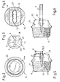
- a hose fitting according to the invention for the manufacture of a hose 1 with at least two, in the illustrated case three, hose chambers 2, 3, 4, in particular for a spray hose determined.
- the hose chambers, which are separated from one another by separating webs 5, 6, may have pressure-opening spray slots which are distributed in sections over the hose length to the individual hose chambers 2, 3, 4.
- Each tube chamber 2, 3, 4 is a Einstecknippel 7, 8, 9 assigned, each having an unspecified inner channel.
- the Einstecknippel 7, 8, 9 are connected to an orifice plate 13 and preferably designed in one piece, the through-openings 10, 11, 12 has.
- the insertion nipple 7, 8, 9 can be the same be formed long or in the ability to assemble promotional - as shown - preferably have a different length, in particular at least one Einstecknippel 8, preferably a centrally arranged Einstecknippel 8, is longer than the other Einstecknippel 7, 9th
- the hose fitting according to the invention further comprises a clamping device 14 which is partly formed of a slotted ring 15 and the other part of a screw-on sleeve 16 which is designed in the manner of a union nut and can be screwed onto the ring 15.
- the ring 15 which has a length L, has at one end a male thread portion 17 extending over at least part of this length L, onto which the screw sleeve 16 can be screwed, and at the other end an insertion opening 18 for the tube 1.
- the screw sleeve 16 is in Fig. 1 shown in two different versions 16a, 16b.
- the screw sleeve 16 is designed as a closure part 16a
- a design 16b is shown in which the screw sleeve 16 has a hose connection part 19, in particular designed as a plug connection part.
- Both for the first embodiment 16 a, as well as for the second embodiment 16 b of the screw can be provided that this - like the item illustration in Fig. 2 shows - are bolted to the ring 15 with the interposition of a sealing ring 20.
- Fig. 3 also shows a detail of the parts connected to the orifice plate 13 Einstecknippel 7, 8, 9, which together form an insert 21 for the ring 15.
- the insert 21 of the orifice plate 13 and Einstecknippeln 7, 8, 9 is fixedly connected to the ring 15, for example, latched, or may be integral with the ring 15.
- the ring has a slot 22, preferably two slots 22, which are in particular of a similar design and each other on the ring 15 circumferentially opposite.
- the slot 22 extends in the longitudinal direction of the Ring 15, but not over the entire length L, but so incomplete that the male threaded portion 17 has an unslotted end portion 23 at its free end.
- Each slot 22 is at least in an assembly of the tube 1 V-shaped counter to the direction of the hose heresteckenden, in particular elastic spring-back, expandable. As a result, a simple insertion of the tube 1 is favored.
- the male threaded portion 17 is formed in the illustrated embodiment of the invention in the sense of a material-saving design, at least in an end unspecified area hollow cylindrical. In this area, the insert part 21 is introduced (assembly step M1).
- the orifice plate 13 in the illustrated embodiment has a circumferential, the stabilization serving edge web 24.
- this edge web 24 can be omitted.
- the tube 1 is then inserted through the insertion opening 18 in the ring 15, wherein the Einstecknippel 7, 8, 9 are inserted into the inner channels of the tube 15.
- the distances and outer diameter of the Einstecknippel 7, 8, 9 must to the inner diameter and the arrangement of the channels 2, 3, 4 correspond.
- the orifice plate 13 comes to lie in the front end region of the spray hose 1. In this case, a simple insertion is possible in that the slot 22 is widened or expandable in a V-shape counter to the direction of the hose 1 to be inserted.
- the slot 22, preferably both slots 22, are arranged such that each slot 22 extends in the assembled state along the narrow side S of the tube 1.
- the screw sleeve 16 for the connection of hoses 1 or - like Fig. 7 shows - be designed as a closure part 16a.
- a hose 1 can be used in a simple and constructively low-cost manner, in which the chambers 2, 3, 4 are made of a polymeric material or are surrounded, at one end 29th , in particular at the end 29, which is opposite to an end with a hose fitting, which has a screw sleeve 16 with a hose connection part 19, is closed by a weld 30.
- a weld can be produced in a technologically less complicated manner by the known welding methods used in polymers and ensures the required pressure-tightness of the hose 1 in the operating state.
- the present invention is not limited to the illustrated embodiment. So z. B. the number and shape of the tube chambers and the cross-sectional contour of the tube 1 differ from the illustrated example, without departing from the scope of the invention.
Landscapes
- Engineering & Computer Science (AREA)
- General Engineering & Computer Science (AREA)
- Mechanical Engineering (AREA)
- Supports For Pipes And Cables (AREA)
- Joints That Cut Off Fluids, And Hose Joints (AREA)
- Rigid Pipes And Flexible Pipes (AREA)
- Lining Or Joining Of Plastics Or The Like (AREA)
Claims (19)
- Accessoire de raccordement pour un tuyau flexible (1) muni d'au moins deux chambres (2, 3, 4), en particulier pour un flexible de pulvérisation, comportant des raccords enfichables (7, 8, 9), associés à chacune des chambres (2, 3, 4) et munis chacun d'un conduit intérieur, et comportant une plaque d'embouchure (13), qui est munie d'ouvertures (10, 11, 12) débouchantes et à laquelle sont reliés les raccords enfichables (7, 8, 9), et comportant un dispositif de serrage (14), formé, d'une part, par une bague (15), qui est munie d'une fente (22) et comprend une longueur (L), une partie à filetage extérieur (17) qui s'étend au niveau d'une extrémité sur au moins une partie de cette longueur (L) et, au niveau de l'autre extrémité, une ouverture d'enfichage (18) pour le tuyau flexible (1), et, d'autre part, par un manchon fileté (16, 16a, 16b) réalisé à la manière d'un écrou d'accouplement et apte à être vissé sur la partie à filetage extérieur (17) de la bague (15), la plaque d'embouchure (13) pouvant, conjointement avec les raccords enfichables (7, 8, 9), être assemblée de manière fixe avec la bague (15) ou être réalisée d'un seul tenant avec la bague (15), caractérisé en ce que la fente (22) de la bague (15) s'étend dans la direction longitudinale incomplètement sur la longueur (L) de la bague (15), de telle sorte que la partie à filetage extérieur (17) comporte, au niveau de son extrémité libre, une zone d'extrémité (23) non fendue.
- Accessoire de raccordement pour tuyau flexible selon la revendication 1,
caractérisé en ce que la bague (15) comporte deux fentes (22), qui sont réalisées en particulier de manière identique et sont disposées en regard l'une de l'autre sur le pourtour de la bague (15). - Accessoire de raccordement pour tuyau flexible selon la revendication 1 ou 2,
caractérisé en ce que chaque fente (22), au moins lors du montage du tuyau flexible (1), peut s'élargir en forme de V, en particulier de manière à revenir élastiquement en position initiale, dans le sens opposé au sens du tuyau flexible (1) à enficher ou est réalisée avec un élargissement en forme de V. - Accessoire de raccordement pour tuyau flexible selon l'une quelconque des revendications 1 à 3,
caractérisé en ce que pour recevoir un tuyau flexible (1) plat, par exemple un tuyau flexible (1) avec au moins trois chambres (2, 3, 4) juxtaposées, qui comporte un côté large (B) et un côté étroit (S), la fente (22), de préférence les deux fentes (22), sont disposées de telle sorte que chaque fente (22), dans la position de montage, s'étend le long du côté étroit (S) du tuyau flexible (1). - Accessoire de raccordement pour tuyau flexible selon l'une quelconque des revendications 1 à 4,
caractérisé en ce que la plaque d'embouchure (13) comporte un rebord (24) périphérique. - Accessoire de raccordement pour tuyau flexible selon l'une quelconque des revendications 1 à 5,
caractérisé en ce que la partie à filetage extérieur (17), au moins dans une zone du côté extrémité, est réalisée en forme de cylindre creux. - Accessoire de raccordement pour tuyau flexible selon la revendication 6,
caractérisé en ce que la zone cylindrique creuse comporte un appui intérieur, tel qu'une nervure intérieure périphérique, pour la plaque d'embouchure (13). - Accessoire de raccordement pour tuyau flexible selon la revendication 6 ou 7,
caractérisé en ce que la zone cylindrique creuse enserre avec sa paroi, de manière ajustée en forme, la plaque d'embouchure (13) et, le cas échéant, le rebord (24). - Accessoire de raccordement pour tuyau flexible selon l'une quelconque des revendications 1 à 8,
caractérisé en ce que la plaque d'embouchure (13) est disposée dans une profondeur axiale à l'intérieur de la bague (15), laquelle n'est pas plus grande, de préférence est aussi grande qu'une longueur axiale (LU) de la zone d'extrémité (23) non fendue. - Accessoire de raccordement pour tuyau flexible selon l'une quelconque des revendications 5 à 9,
caractérisé en ce que le rebord (23) périphérique de la plaque d'embouchure (13) se termine à fleur de la partie à filetage extérieur (17) de la bague (15). - Accessoire de raccordement pour tuyau flexible selon l'une quelconque des revendications 1 à 10,
caractérisé en ce que la plaque d'embouchure (13) est réalisée d'un seul tenant avec les raccords enfichables (7, 8, 9) et, en particulier, en plus, aussi d'un seul tenant avec la bague (15). - Accessoire de raccordement pour tuyau flexible selon l'une quelconque des revendications 1 à 10,
caractérisé en ce que la plaque d'embouchure (13) peut être encliquetée sur la bague (15). - Accessoire de raccordement pour tuyau flexible selon l'une quelconque des revendications 1 à 12,
caractérisé en ce que les raccords enfichables (7, 8, 9) sont réalisés avec des longueurs différentes, en particulier au moins un raccord enfichable (8), de préférence un raccord enfichable (8) disposé au centre, étant plus long que les autres raccords enfichables (7, 9). - Accessoire de raccordement pour tuyau flexible selon l'une quelconque des revendications 1 à 12,
caractérisé en ce que les raccords enfichables (7, 8, 9) sont réalisés avec la même longueur. - Accessoire de raccordement pour tuyau flexible selon l'une quelconque des revendications 1 à 14,
caractérisé en ce qu'au moins un des raccords enfichables (7, 8, 9) est disposé à fleur avec une arête frontale (25) de l'ouverture d'enfichage (18) ou s'avance au-delà de cette arête frontale (25) (débord Ü). - Accessoire de raccordement pour tuyau flexible selon l'une quelconque des revendications 1 à 15,
caractérisé en ce que les raccords enfichables (7, 8, 9), au niveau de leurs extrémités détournées de la plaque d'embouchure (13), comportent des zones annulaires (26, 27, 28) faisant saillie radialement, réalisées en particulier avec une forme conique. - Accessoire de raccordement pour tuyau flexible selon l'une quelconque des revendications 1 à 16,
caractérisé en ce que le contour intérieur de l'ouverture d'enfichage (18) pour le tuyau flexible (1) est réalisé de telle sorte que, dans la position de montage, il enserre, de manière ajustée en forme, le contour extérieur de la section du tuyau flexible (1), moyennant la formation d'un ajustement serré. - Accessoire de raccordement pour tuyau flexible selon l'une quelconque des revendications 1 à 17,
caractérisé en ce que le manchon fileté (16, 16b) comporte un élément d'assemblage fileté (19), réalisé en particulier sous la forme d'un assemblage à enficher. - Accessoire de raccordement pour tuyau flexible selon l'une quelconque des revendications 1 à 17,
caractérisé en ce que le manchon fileté (16, 16b) est réalisé sous la forme d'un élément de fermeture (16a).
Priority Applications (2)
| Application Number | Priority Date | Filing Date | Title |
|---|---|---|---|
| SI200830046T SI1970614T1 (sl) | 2007-01-12 | 2008-01-09 | Cevna armatura za gibko cev z več komorami |
| PL08150114T PL1970614T3 (pl) | 2007-01-12 | 2008-01-09 | Armatura wężowa do węża z wieloma kanałami |
Applications Claiming Priority (1)
| Application Number | Priority Date | Filing Date | Title |
|---|---|---|---|
| DE202007000761U DE202007000761U1 (de) | 2007-01-12 | 2007-01-12 | Schlaucharmatur für einen Schlauch mit mehreren Schlauchkammern und Mehrkammerschlauch zum Anchluss an eine solche Armatur |
Publications (2)
| Publication Number | Publication Date |
|---|---|
| EP1970614A1 EP1970614A1 (fr) | 2008-09-17 |
| EP1970614B1 true EP1970614B1 (fr) | 2010-07-21 |
Family
ID=39400109
Family Applications (1)
| Application Number | Title | Priority Date | Filing Date |
|---|---|---|---|
| EP08150114A Not-in-force EP1970614B1 (fr) | 2007-01-12 | 2008-01-09 | Armature de tuyau souple pour un tuyau souple doté de plusieurs chambres |
Country Status (8)
| Country | Link |
|---|---|
| EP (1) | EP1970614B1 (fr) |
| AT (1) | ATE475045T1 (fr) |
| DE (2) | DE202007000761U1 (fr) |
| DK (1) | DK1970614T3 (fr) |
| ES (1) | ES2346268T3 (fr) |
| PL (1) | PL1970614T3 (fr) |
| PT (1) | PT1970614E (fr) |
| SI (1) | SI1970614T1 (fr) |
Cited By (1)
| Publication number | Priority date | Publication date | Assignee | Title |
|---|---|---|---|---|
| EP4644175A1 (fr) * | 2024-05-01 | 2025-11-05 | Lear Corporation | Connecteur avec pince pour fixer des canaux d'air de vessie gonflable |
Families Citing this family (2)
| Publication number | Priority date | Publication date | Assignee | Title |
|---|---|---|---|---|
| DE102019129828A1 (de) * | 2019-11-05 | 2021-05-06 | Norma Germany Gmbh | Verbinder und Verbinderanordnung für Mehrkammerprofile und/oder -leitungen |
| US12474006B2 (en) | 2022-01-26 | 2025-11-18 | Noetic Technologies Inc. | Fluid manifold connector apparatus |
Family Cites Families (7)
| Publication number | Priority date | Publication date | Assignee | Title |
|---|---|---|---|---|
| GB903304A (en) * | 1959-01-14 | 1962-08-15 | Windolite Ltd | Improvements in or relating to devices for the spraying of water or other fluids |
| GB8316384D0 (en) * | 1983-06-16 | 1983-07-20 | Sanders B | Hose |
| DE3537077A1 (de) * | 1985-04-13 | 1986-10-23 | behkaplast Gesellschaft für Kunststoffverarbeitung mbH, 4056 Schwalmtal | Spruehschlauch |
| DE8606136U1 (de) * | 1986-03-06 | 1986-04-17 | Gardena Kress + Kastner Gmbh, 7900 Ulm | Flachschlauch mit einer Anschlußarmatur |
| DE8811174U1 (de) * | 1988-09-03 | 1990-01-04 | Houben Kunststofftechnik GmbH, 4060 Viersen | Kupplungsstück für Flachschläuche |
| CA2409900C (fr) * | 2002-10-29 | 2005-02-08 | Global Industries Holdings Ltd. | Tuyau d'arrosage plat et raccords pour tuyau d'arrosage plat |
| US6951227B1 (en) * | 2004-04-20 | 2005-10-04 | Cheng-Wen Su | Hose with multiple holes |
-
2007
- 2007-01-12 DE DE202007000761U patent/DE202007000761U1/de not_active Expired - Lifetime
-
2008
- 2008-01-09 EP EP08150114A patent/EP1970614B1/fr not_active Not-in-force
- 2008-01-09 SI SI200830046T patent/SI1970614T1/sl unknown
- 2008-01-09 ES ES08150114T patent/ES2346268T3/es active Active
- 2008-01-09 PT PT08150114T patent/PT1970614E/pt unknown
- 2008-01-09 PL PL08150114T patent/PL1970614T3/pl unknown
- 2008-01-09 DE DE502008000970T patent/DE502008000970D1/de active Active
- 2008-01-09 DK DK08150114.0T patent/DK1970614T3/da active
- 2008-01-09 AT AT08150114T patent/ATE475045T1/de active
Cited By (1)
| Publication number | Priority date | Publication date | Assignee | Title |
|---|---|---|---|---|
| EP4644175A1 (fr) * | 2024-05-01 | 2025-11-05 | Lear Corporation | Connecteur avec pince pour fixer des canaux d'air de vessie gonflable |
Also Published As
| Publication number | Publication date |
|---|---|
| DK1970614T3 (da) | 2010-11-15 |
| ES2346268T3 (es) | 2010-10-13 |
| DE202007000761U1 (de) | 2008-05-15 |
| PL1970614T3 (pl) | 2010-12-31 |
| ATE475045T1 (de) | 2010-08-15 |
| SI1970614T1 (sl) | 2010-08-31 |
| PT1970614E (pt) | 2010-09-03 |
| DE502008000970D1 (de) | 2010-09-02 |
| EP1970614A1 (fr) | 2008-09-17 |
Similar Documents
| Publication | Publication Date | Title |
|---|---|---|
| DE102004032572B4 (de) | Verbindungsanordnung mit Kontaktstift | |
| EP1931904B1 (fr) | Piece de liaison et de raccordement destinee a des tubes ondules | |
| EP3173675B1 (fr) | Raccord de tuyau | |
| EP2724065B1 (fr) | Raccord de tuyau flexible et système de tuyau flexible correspondant | |
| DE102004052475A1 (de) | Zugfeste Steckkupplung | |
| DE19652838A1 (de) | Stecker einer elektrischen Steckverbindung und elektrische Steckverbindung | |
| DE102004014988A1 (de) | Kupplung für Kraftstoffsystemkomponenten | |
| DE19621535A1 (de) | Steckkupplung für Druckmittelsysteme | |
| EP1070215A1 (fr) | Dispositif pour raccorder une tubulure, une piece de robinetterie ou un raccord tubulaire a un tuyau | |
| DE19747959A1 (de) | Steckverbindung | |
| EP0549860B1 (fr) | Dispositif d'accouplement de deux conduites, en particulier pour des conduites de carburant | |
| DE202006012625U1 (de) | Entwässerungsvorrichtung | |
| DE69608289T2 (de) | Verbindungsanordnung für mehrkanalrohrleitungssystem | |
| EP1970614B1 (fr) | Armature de tuyau souple pour un tuyau souple doté de plusieurs chambres | |
| DE20318583U1 (de) | Ladesteckverbindersatz mit Adapter | |
| EP3339928A1 (fr) | Dispositif de connexion et boîte de distribution de fibres de verre | |
| EP4158233B1 (fr) | Fiche de connexion et ensemble fiche formé à partir de celle-ci | |
| EP1769183B1 (fr) | Piece de raccordement et d'assemblage pour tubes ondules | |
| WO2014032194A1 (fr) | Dispositif d'isolation pour l'isolation ultérieure de raccords de tuyaux | |
| WO2015044067A2 (fr) | Dispositif servant à la traversée étanche de lignes à travers un élément de séparation | |
| EP3189263B1 (fr) | Dispositif de raccordement pour une conduite de fluide | |
| EP1006307B1 (fr) | Raccord enfichable | |
| AT388426B (de) | Kupplungsanordnung fuer wenigstens eine rohrleitung sowie dichtunsstopfen hiefuer | |
| EP1467451A1 (fr) | Coupleur de connecteur coaxial | |
| WO2016058791A1 (fr) | Dispositif d'assemblage de tuyaux |
Legal Events
| Date | Code | Title | Description |
|---|---|---|---|
| PUAI | Public reference made under article 153(3) epc to a published international application that has entered the european phase |
Free format text: ORIGINAL CODE: 0009012 |
|
| AK | Designated contracting states |
Kind code of ref document: A1 Designated state(s): AT BE BG CH CY CZ DE DK EE ES FI FR GB GR HR HU IE IS IT LI LT LU LV MC MT NL NO PL PT RO SE SI SK TR |
|
| AX | Request for extension of the european patent |
Extension state: AL BA MK |
|
| 17P | Request for examination filed |
Effective date: 20090302 |
|
| AKX | Designation fees paid |
Designated state(s): AT BE BG CH CY CZ DE DK EE ES FI FR GB GR HR HU IE IS IT LI LT LU LV MC MT NL NO PL PT RO SE SI SK TR |
|
| 17Q | First examination report despatched |
Effective date: 20090618 |
|
| GRAP | Despatch of communication of intention to grant a patent |
Free format text: ORIGINAL CODE: EPIDOSNIGR1 |
|
| RTI1 | Title (correction) |
Free format text: HOSE FITTING FOR A HOSE WITH MULTIPLE CHAMBERS |
|
| GRAS | Grant fee paid |
Free format text: ORIGINAL CODE: EPIDOSNIGR3 |
|
| GRAA | (expected) grant |
Free format text: ORIGINAL CODE: 0009210 |
|
| AK | Designated contracting states |
Kind code of ref document: B1 Designated state(s): AT BE BG CH CY CZ DE DK EE ES FI FR GB GR HR HU IE IS IT LI LT LU LV MC MT NL NO PL PT RO SE SI SK TR |
|
| REG | Reference to a national code |
Ref country code: GB Ref legal event code: FG4D Free format text: NOT ENGLISH |
|
| REG | Reference to a national code |
Ref country code: CH Ref legal event code: EP Ref country code: CH Ref legal event code: NV Representative=s name: BRAUNPAT BRAUN EDER AG |
|
| REG | Reference to a national code |
Ref country code: IE Ref legal event code: FG4D |
|
| REG | Reference to a national code |
Ref country code: NL Ref legal event code: T3 |
|
| REF | Corresponds to: |
Ref document number: 502008000970 Country of ref document: DE Date of ref document: 20100902 Kind code of ref document: P |
|
| REG | Reference to a national code |
Ref country code: PT Ref legal event code: SC4A Free format text: AVAILABILITY OF NATIONAL TRANSLATION Effective date: 20100726 |
|
| REG | Reference to a national code |
Ref country code: GR Ref legal event code: EP Ref document number: 20100401843 Country of ref document: GR |
|
| REG | Reference to a national code |
Ref country code: ES Ref legal event code: FG2A Ref document number: 2346268 Country of ref document: ES Kind code of ref document: T3 |
|
| REG | Reference to a national code |
Ref country code: SE Ref legal event code: TRGR |
|
| REG | Reference to a national code |
Ref country code: DK Ref legal event code: T3 |
|
| LTIE | Lt: invalidation of european patent or patent extension |
Effective date: 20100721 |
|
| REG | Reference to a national code |
Ref country code: PL Ref legal event code: T3 |
|
| PG25 | Lapsed in a contracting state [announced via postgrant information from national office to epo] |
Ref country code: FI Free format text: LAPSE BECAUSE OF FAILURE TO SUBMIT A TRANSLATION OF THE DESCRIPTION OR TO PAY THE FEE WITHIN THE PRESCRIBED TIME-LIMIT Effective date: 20100721 Ref country code: NO Free format text: LAPSE BECAUSE OF FAILURE TO SUBMIT A TRANSLATION OF THE DESCRIPTION OR TO PAY THE FEE WITHIN THE PRESCRIBED TIME-LIMIT Effective date: 20101021 Ref country code: LT Free format text: LAPSE BECAUSE OF FAILURE TO SUBMIT A TRANSLATION OF THE DESCRIPTION OR TO PAY THE FEE WITHIN THE PRESCRIBED TIME-LIMIT Effective date: 20100721 |
|
| PGFP | Annual fee paid to national office [announced via postgrant information from national office to epo] |
Ref country code: MC Payment date: 20101130 Year of fee payment: 4 |
|
| PG25 | Lapsed in a contracting state [announced via postgrant information from national office to epo] |
Ref country code: BG Free format text: LAPSE BECAUSE OF FAILURE TO SUBMIT A TRANSLATION OF THE DESCRIPTION OR TO PAY THE FEE WITHIN THE PRESCRIBED TIME-LIMIT Effective date: 20101021 Ref country code: IS Free format text: LAPSE BECAUSE OF FAILURE TO SUBMIT A TRANSLATION OF THE DESCRIPTION OR TO PAY THE FEE WITHIN THE PRESCRIBED TIME-LIMIT Effective date: 20101121 Ref country code: HR Free format text: LAPSE BECAUSE OF FAILURE TO SUBMIT A TRANSLATION OF THE DESCRIPTION OR TO PAY THE FEE WITHIN THE PRESCRIBED TIME-LIMIT Effective date: 20100721 Ref country code: CY Free format text: LAPSE BECAUSE OF FAILURE TO SUBMIT A TRANSLATION OF THE DESCRIPTION OR TO PAY THE FEE WITHIN THE PRESCRIBED TIME-LIMIT Effective date: 20100721 |
|
| PGFP | Annual fee paid to national office [announced via postgrant information from national office to epo] |
Ref country code: CZ Payment date: 20101203 Year of fee payment: 4 |
|
| PG25 | Lapsed in a contracting state [announced via postgrant information from national office to epo] |
Ref country code: LV Free format text: LAPSE BECAUSE OF FAILURE TO SUBMIT A TRANSLATION OF THE DESCRIPTION OR TO PAY THE FEE WITHIN THE PRESCRIBED TIME-LIMIT Effective date: 20100721 |
|
| PLBE | No opposition filed within time limit |
Free format text: ORIGINAL CODE: 0009261 |
|
| STAA | Information on the status of an ep patent application or granted ep patent |
Free format text: STATUS: NO OPPOSITION FILED WITHIN TIME LIMIT |
|
| PG25 | Lapsed in a contracting state [announced via postgrant information from national office to epo] |
Ref country code: RO Free format text: LAPSE BECAUSE OF FAILURE TO SUBMIT A TRANSLATION OF THE DESCRIPTION OR TO PAY THE FEE WITHIN THE PRESCRIBED TIME-LIMIT Effective date: 20100721 Ref country code: EE Free format text: LAPSE BECAUSE OF FAILURE TO SUBMIT A TRANSLATION OF THE DESCRIPTION OR TO PAY THE FEE WITHIN THE PRESCRIBED TIME-LIMIT Effective date: 20100721 Ref country code: SK Free format text: LAPSE BECAUSE OF FAILURE TO SUBMIT A TRANSLATION OF THE DESCRIPTION OR TO PAY THE FEE WITHIN THE PRESCRIBED TIME-LIMIT Effective date: 20100721 |
|
| PGFP | Annual fee paid to national office [announced via postgrant information from national office to epo] |
Ref country code: PL Payment date: 20110103 Year of fee payment: 4 Ref country code: LU Payment date: 20110215 Year of fee payment: 4 |
|
| 26N | No opposition filed |
Effective date: 20110426 |
|
| BERE | Be: lapsed |
Owner name: MEISTER PLAST G.M.B.H. Effective date: 20110131 |
|
| REG | Reference to a national code |
Ref country code: DE Ref legal event code: R097 Ref document number: 502008000970 Country of ref document: DE Effective date: 20110426 |
|
| PG25 | Lapsed in a contracting state [announced via postgrant information from national office to epo] |
Ref country code: BE Free format text: LAPSE BECAUSE OF NON-PAYMENT OF DUE FEES Effective date: 20110131 |
|
| PG25 | Lapsed in a contracting state [announced via postgrant information from national office to epo] |
Ref country code: MT Free format text: LAPSE BECAUSE OF FAILURE TO SUBMIT A TRANSLATION OF THE DESCRIPTION OR TO PAY THE FEE WITHIN THE PRESCRIBED TIME-LIMIT Effective date: 20100721 |
|
| PGFP | Annual fee paid to national office [announced via postgrant information from national office to epo] |
Ref country code: FR Payment date: 20120217 Year of fee payment: 5 Ref country code: IE Payment date: 20120210 Year of fee payment: 5 Ref country code: CH Payment date: 20120214 Year of fee payment: 5 |
|
| PGFP | Annual fee paid to national office [announced via postgrant information from national office to epo] |
Ref country code: SI Payment date: 20120217 Year of fee payment: 5 Ref country code: PT Payment date: 20120207 Year of fee payment: 5 Ref country code: DE Payment date: 20120328 Year of fee payment: 5 |
|
| PGFP | Annual fee paid to national office [announced via postgrant information from national office to epo] |
Ref country code: GR Payment date: 20120131 Year of fee payment: 5 Ref country code: GB Payment date: 20120201 Year of fee payment: 5 Ref country code: IT Payment date: 20120131 Year of fee payment: 5 Ref country code: SE Payment date: 20120131 Year of fee payment: 5 Ref country code: DK Payment date: 20120131 Year of fee payment: 5 |
|
| PGFP | Annual fee paid to national office [announced via postgrant information from national office to epo] |
Ref country code: NL Payment date: 20120201 Year of fee payment: 5 |
|
| PG25 | Lapsed in a contracting state [announced via postgrant information from national office to epo] |
Ref country code: MC Free format text: LAPSE BECAUSE OF NON-PAYMENT OF DUE FEES Effective date: 20120131 |
|
| PGFP | Annual fee paid to national office [announced via postgrant information from national office to epo] |
Ref country code: ES Payment date: 20120215 Year of fee payment: 5 |
|
| REG | Reference to a national code |
Ref country code: PT Ref legal event code: MM4A Free format text: LAPSE DUE TO NON-PAYMENT OF FEES Effective date: 20130709 |
|
| REG | Reference to a national code |
Ref country code: NL Ref legal event code: V1 Effective date: 20130801 |
|
| REG | Reference to a national code |
Ref country code: DK Ref legal event code: EBP |
|
| REG | Reference to a national code |
Ref country code: CH Ref legal event code: PL |
|
| REG | Reference to a national code |
Ref country code: SE Ref legal event code: EUG |
|
| GBPC | Gb: european patent ceased through non-payment of renewal fee |
Effective date: 20130109 |
|
| PG25 | Lapsed in a contracting state [announced via postgrant information from national office to epo] |
Ref country code: TR Free format text: LAPSE BECAUSE OF FAILURE TO SUBMIT A TRANSLATION OF THE DESCRIPTION OR TO PAY THE FEE WITHIN THE PRESCRIBED TIME-LIMIT Effective date: 20100721 |
|
| REG | Reference to a national code |
Ref country code: GR Ref legal event code: ML Ref document number: 20100401843 Country of ref document: GR Effective date: 20130802 |
|
| REG | Reference to a national code |
Ref country code: IE Ref legal event code: MM4A |
|
| REG | Reference to a national code |
Ref country code: FR Ref legal event code: ST Effective date: 20130930 |
|
| REG | Reference to a national code |
Ref country code: SI Ref legal event code: KO00 Effective date: 20130906 |
|
| PG25 | Lapsed in a contracting state [announced via postgrant information from national office to epo] |
Ref country code: DE Free format text: LAPSE BECAUSE OF NON-PAYMENT OF DUE FEES Effective date: 20130801 Ref country code: SE Free format text: LAPSE BECAUSE OF NON-PAYMENT OF DUE FEES Effective date: 20130110 Ref country code: CZ Free format text: LAPSE BECAUSE OF NON-PAYMENT OF DUE FEES Effective date: 20130109 Ref country code: LI Free format text: LAPSE BECAUSE OF NON-PAYMENT OF DUE FEES Effective date: 20130131 Ref country code: PT Free format text: LAPSE BECAUSE OF NON-PAYMENT OF DUE FEES Effective date: 20130709 Ref country code: NL Free format text: LAPSE BECAUSE OF NON-PAYMENT OF DUE FEES Effective date: 20130801 Ref country code: SI Free format text: LAPSE BECAUSE OF NON-PAYMENT OF DUE FEES Effective date: 20130110 Ref country code: GR Free format text: LAPSE BECAUSE OF NON-PAYMENT OF DUE FEES Effective date: 20130802 Ref country code: CH Free format text: LAPSE BECAUSE OF NON-PAYMENT OF DUE FEES Effective date: 20130131 Ref country code: HU Free format text: LAPSE BECAUSE OF FAILURE TO SUBMIT A TRANSLATION OF THE DESCRIPTION OR TO PAY THE FEE WITHIN THE PRESCRIBED TIME-LIMIT Effective date: 20100721 |
|
| REG | Reference to a national code |
Ref country code: DE Ref legal event code: R119 Ref document number: 502008000970 Country of ref document: DE Effective date: 20130801 |
|
| PG25 | Lapsed in a contracting state [announced via postgrant information from national office to epo] |
Ref country code: GB Free format text: LAPSE BECAUSE OF NON-PAYMENT OF DUE FEES Effective date: 20130109 Ref country code: FR Free format text: LAPSE BECAUSE OF NON-PAYMENT OF DUE FEES Effective date: 20130131 |
|
| PG25 | Lapsed in a contracting state [announced via postgrant information from national office to epo] |
Ref country code: IT Free format text: LAPSE BECAUSE OF NON-PAYMENT OF DUE FEES Effective date: 20130109 |
|
| PG25 | Lapsed in a contracting state [announced via postgrant information from national office to epo] |
Ref country code: DK Free format text: LAPSE BECAUSE OF NON-PAYMENT OF DUE FEES Effective date: 20130131 Ref country code: IE Free format text: LAPSE BECAUSE OF NON-PAYMENT OF DUE FEES Effective date: 20130109 |
|
| REG | Reference to a national code |
Ref country code: AT Ref legal event code: MM01 Ref document number: 475045 Country of ref document: AT Kind code of ref document: T Effective date: 20130109 |
|
| REG | Reference to a national code |
Ref country code: PL Ref legal event code: LAPE |
|
| PG25 | Lapsed in a contracting state [announced via postgrant information from national office to epo] |
Ref country code: AT Free format text: LAPSE BECAUSE OF NON-PAYMENT OF DUE FEES Effective date: 20130109 Ref country code: LU Free format text: LAPSE BECAUSE OF NON-PAYMENT OF DUE FEES Effective date: 20120109 Ref country code: PL Free format text: LAPSE BECAUSE OF NON-PAYMENT OF DUE FEES Effective date: 20130109 |
|
| REG | Reference to a national code |
Ref country code: ES Ref legal event code: FD2A Effective date: 20150708 |
|
| PG25 | Lapsed in a contracting state [announced via postgrant information from national office to epo] |
Ref country code: ES Free format text: LAPSE BECAUSE OF NON-PAYMENT OF DUE FEES Effective date: 20130110 |