EP1970642A2 - System for solar thermic energy regulation and its use - Google Patents
System for solar thermic energy regulation and its use Download PDFInfo
- Publication number
- EP1970642A2 EP1970642A2 EP08380064A EP08380064A EP1970642A2 EP 1970642 A2 EP1970642 A2 EP 1970642A2 EP 08380064 A EP08380064 A EP 08380064A EP 08380064 A EP08380064 A EP 08380064A EP 1970642 A2 EP1970642 A2 EP 1970642A2
- Authority
- EP
- European Patent Office
- Prior art keywords
- fluid
- mobile
- solar
- solar thermal
- thermal energy
- Prior art date
- Legal status (The legal status is an assumption and is not a legal conclusion. Google has not performed a legal analysis and makes no representation as to the accuracy of the status listed.)
- Withdrawn
Links
- 239000012530 fluid Substances 0.000 claims abstract description 19
- 239000000523 sample Substances 0.000 claims abstract description 15
- 230000032683 aging Effects 0.000 description 3
- 238000009835 boiling Methods 0.000 description 2
- 238000010438 heat treatment Methods 0.000 description 2
- 238000012423 maintenance Methods 0.000 description 2
- 239000000463 material Substances 0.000 description 2
- 238000013021 overheating Methods 0.000 description 2
- 230000004224 protection Effects 0.000 description 2
- 238000009825 accumulation Methods 0.000 description 1
- 239000003344 environmental pollutant Substances 0.000 description 1
- 238000001704 evaporation Methods 0.000 description 1
- 230000008020 evaporation Effects 0.000 description 1
- 238000007710 freezing Methods 0.000 description 1
- 230000008014 freezing Effects 0.000 description 1
- 239000007792 gaseous phase Substances 0.000 description 1
- 239000012535 impurity Substances 0.000 description 1
- 238000007689 inspection Methods 0.000 description 1
- 238000009434 installation Methods 0.000 description 1
- 239000007788 liquid Substances 0.000 description 1
- 239000007791 liquid phase Substances 0.000 description 1
- 238000005259 measurement Methods 0.000 description 1
- 230000000737 periodic effect Effects 0.000 description 1
- 231100000719 pollutant Toxicity 0.000 description 1
- 238000010926 purge Methods 0.000 description 1
- 238000000926 separation method Methods 0.000 description 1
- 239000005315 stained glass Substances 0.000 description 1
- 230000009182 swimming Effects 0.000 description 1
- 230000009466 transformation Effects 0.000 description 1
- XLYOFNOQVPJJNP-UHFFFAOYSA-N water Substances O XLYOFNOQVPJJNP-UHFFFAOYSA-N 0.000 description 1
Images

Classifications
-
- F—MECHANICAL ENGINEERING; LIGHTING; HEATING; WEAPONS; BLASTING
- F24—HEATING; RANGES; VENTILATING
- F24S—SOLAR HEAT COLLECTORS; SOLAR HEAT SYSTEMS
- F24S50/00—Arrangements for controlling solar heat collectors
- F24S50/80—Arrangements for controlling solar heat collectors for controlling collection or absorption of solar radiation
-
- E—FIXED CONSTRUCTIONS
- E05—LOCKS; KEYS; WINDOW OR DOOR FITTINGS; SAFES
- E05F—DEVICES FOR MOVING WINGS INTO OPEN OR CLOSED POSITION; CHECKS FOR WINGS; WING FITTINGS NOT OTHERWISE PROVIDED FOR, CONCERNED WITH THE FUNCTIONING OF THE WING
- E05F15/00—Power-operated mechanisms for wings
- E05F15/70—Power-operated mechanisms for wings with automatic actuation
- E05F15/71—Power-operated mechanisms for wings with automatic actuation responsive to temperature changes, rain, wind or noise
-
- E—FIXED CONSTRUCTIONS
- E06—DOORS, WINDOWS, SHUTTERS, OR ROLLER BLINDS IN GENERAL; LADDERS
- E06B—FIXED OR MOVABLE CLOSURES FOR OPENINGS IN BUILDINGS, VEHICLES, FENCES OR LIKE ENCLOSURES IN GENERAL, e.g. DOORS, WINDOWS, BLINDS, GATES
- E06B9/00—Screening or protective devices for wall or similar openings, with or without operating or securing mechanisms; Closures of similar construction
- E06B9/24—Screens or other constructions affording protection against light, especially against sunshine; Similar screens for privacy or appearance; Slat blinds
- E06B9/26—Lamellar or like blinds, e.g. venetian blinds
-
- F—MECHANICAL ENGINEERING; LIGHTING; HEATING; WEAPONS; BLASTING
- F24—HEATING; RANGES; VENTILATING
- F24S—SOLAR HEAT COLLECTORS; SOLAR HEAT SYSTEMS
- F24S40/00—Safety or protection arrangements of solar heat collectors; Preventing malfunction of solar heat collectors
- F24S40/10—Protective covers or shrouds; Closure members, e.g. lids
-
- F—MECHANICAL ENGINEERING; LIGHTING; HEATING; WEAPONS; BLASTING
- F24—HEATING; RANGES; VENTILATING
- F24S—SOLAR HEAT COLLECTORS; SOLAR HEAT SYSTEMS
- F24S40/00—Safety or protection arrangements of solar heat collectors; Preventing malfunction of solar heat collectors
- F24S40/50—Preventing overheating or overpressure
- F24S40/52—Preventing overheating or overpressure by modifying the heat collection, e.g. by defocusing or by changing the position of heat-receiving elements
-
- F—MECHANICAL ENGINEERING; LIGHTING; HEATING; WEAPONS; BLASTING
- F24—HEATING; RANGES; VENTILATING
- F24S—SOLAR HEAT COLLECTORS; SOLAR HEAT SYSTEMS
- F24S50/00—Arrangements for controlling solar heat collectors
- F24S50/40—Arrangements for controlling solar heat collectors responsive to temperature
-
- Y—GENERAL TAGGING OF NEW TECHNOLOGICAL DEVELOPMENTS; GENERAL TAGGING OF CROSS-SECTIONAL TECHNOLOGIES SPANNING OVER SEVERAL SECTIONS OF THE IPC; TECHNICAL SUBJECTS COVERED BY FORMER USPC CROSS-REFERENCE ART COLLECTIONS [XRACs] AND DIGESTS
- Y02—TECHNOLOGIES OR APPLICATIONS FOR MITIGATION OR ADAPTATION AGAINST CLIMATE CHANGE
- Y02E—REDUCTION OF GREENHOUSE GAS [GHG] EMISSIONS, RELATED TO ENERGY GENERATION, TRANSMISSION OR DISTRIBUTION
- Y02E10/00—Energy generation through renewable energy sources
- Y02E10/40—Solar thermal energy, e.g. solar towers
Definitions
- the present invention relates to a system for solar thermal energy regulation and its use in facilities powered by solar thermal energy.
- renewable energies among them light energy or thermal energy.
- the energy produced by solar batteries can be used in various applications, like for heating of sanitary water, swimming pools, central heating or several at the same time.
- the object of the present invention is therefore a system for a solar thermal energy regulation which comprises a screen of mobile blades connected with a thermostatic probe immersed in the fluid of the facility circuit.
- the subject of the present invention allows to keep a suitable facility temperature, what at the same time allows to avoid high temperatures and overheating, which normally cause damages, ageing or significant expansion of the fluid causing its subsequent loss.
- the system is automatic and therefore it does not need any other kind of energy, such as electric or combustible, since the temperature of the fluid warmed by the sunlight in the one which activates the mechanism.
- the system for regulation of the solar thermal energy comprises a screen of mobile blades 1, connected with an autonomous thermostatic probe 2 immersed through its bulb 3 in the fluid of the facility circuit 7.
- said thermostatic probe 2 is immersed in the fluid of the solar thermal battery circuit.
- said thermostatic probe 2 is immersed in the environment fluid.
- the system in a preferred embodiment of the invention, comprises a screen of mobile blades 1, which is situated inside a frame 4 and comprises one or more mobile blades secured through their longitudinal axes and joined with the use of a mobile fastening means 5, preferably a flat, connected with said thermostatic probe 2, preferably with the use of a lever 6.
- Said thermostatic probe which is immersed in the fluid, in the one of the battery circuit or in the one of the environment, detects its temperature and activates the movement of mobile fastening means 5. This way it activates the movement of the blades through their axes the way they open, maintain or close the passage of the light towards the inside of the facility powered by the solar thermal energy. That is how it is possible to achieve the temperature, which is necessary and adequate for the used facility, by simple adjustment of the grade of the blades aperture.
- the opened state of the system has been shown on the figure 2
- the closed state of the system has been shown on the figure 3 .
- the system is powered directly or indirectly by the solar thermal energy and never by electric energy or other combustible or pollutant energies. It is simply the temperature of the fluid warmed by the sunlight which activates the mechanism of thermostatic probe 2, which by means of lever 6, connected by fastening mobile means 5, turns the mobile blades 1 closing the system to a necessary degree when the probe detects a proper temperature, this way preventing passage of the excessive sunlight, or opening the system to a necessary degree when there is a need of the heat, this way allowing increase in the passage of the sunlight.
- the system according to the invention can be used in almost any facilities powered by the solar thermal energy, in a preferred embodiment in solar batteries, but also in other types of solar collectors.
- the system can also be used in different spaces, such as compartments, rooms or halls and the like, having skylights, windows or stained-glass apertures oriented in the sunlight direction. Therefore such spaces, due to exposure on excessive sunlight, are at risk of unnecessary high temperatures in their environments.
- By installation of the system according to the invention it is possible to control the internal temperature caused by the sunlight by controlling its passage.
- the measurements of the system depend on a surface of the facility where it is to be mounted, since it should cover the surface substantially entirely in order to assure its maximum efficiency.
- said system allows to reduce ageing of the solar facility, but above all it does not need to be fed by external energy in order to induce the movement of the blades, since its mechanism is automatic.
Landscapes
- Engineering & Computer Science (AREA)
- Chemical & Material Sciences (AREA)
- Physics & Mathematics (AREA)
- Life Sciences & Earth Sciences (AREA)
- Sustainable Development (AREA)
- Sustainable Energy (AREA)
- Thermal Sciences (AREA)
- Combustion & Propulsion (AREA)
- Mechanical Engineering (AREA)
- General Engineering & Computer Science (AREA)
- Structural Engineering (AREA)
- Civil Engineering (AREA)
- Architecture (AREA)
- Photovoltaic Devices (AREA)
Abstract
Description
- The present invention relates to a system for solar thermal energy regulation and its use in facilities powered by solar thermal energy.
- Nowadays there exists a large demand for use of renewable energies, among them light energy or thermal energy. For example, the energy produced by solar batteries can be used in various applications, like for heating of sanitary water, swimming pools, central heating or several at the same time.
- The goal of the existing systems is a maximum use of the light energy. However such systems require some special protections and safety means in order to ensure their proper use and effective functioning.
- In the presently applied facilities there is known the use of chemically treated fluids in the batteries circuits in order to avoid the risk of freezing. Nevertheless, such chemically treated fluids are usually contaminative.
- It is also known the use of expansion vessels which permit to avoid high pressures caused by the expansion of the fluid. Said expansion used to be caused by overheating originated by an excessive exposure on a sunlight. However said tanks are large and therefore significantly reduce the area which otherwise could be assigned as a space for energy accumulation.
- It is also known the use of security valves to prevent overpressures occurring in the hydraulic circuit caused by an excessive exposure on a sunlight. In such situations said valves would be activated in order to protect the system, but at the same time they would cause the loss of the fluid, which would be released from the circuit and directed outside as a drain. It must also be noted that these liquids are usually contaminative.
- On the other hand, high temperatures can cause boiling of the fluid. In this situation it can be observed its transformation from a liquid phase into a gaseous phase, and its subsequent loss through the bubble separation valve or automatic purge.
- According to the above there is an existing need for a system which would permit the exposure on a sunlight required in each moment, allowing to achieve a previously determined temperature adequate for a facility used. This way it could be avoided the occurrence of possible failures, damages or quick ageing of the facility.
- The object of the present invention is therefore a system for a solar thermal energy regulation which comprises a screen of mobile blades connected with a thermostatic probe immersed in the fluid of the facility circuit.
- The subject of the present invention allows to keep a suitable facility temperature, what at the same time allows to avoid high temperatures and overheating, which normally cause damages, ageing or significant expansion of the fluid causing its subsequent loss. What is more, the system is automatic and therefore it does not need any other kind of energy, such as electric or combustible, since the temperature of the fluid warmed by the sunlight in the one which activates the mechanism.
- Is therefore the aim of the present invention also the use of the system in the facilities powered by the solar thermal energy, in particular in solar batteries or in any spaces.
- Embodiments of the present invention will now be described in detail, by way of example, with reference to the accompanying drawings in which:
-
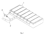
Figure 1 illustrates a general view of the system. -
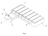
Figure 2 illustrates the system having the mobile blades in the opened state. -
Figure 3 illustrates the system having the mobile blades in the closed state. - The system for regulation of the solar thermal energy according to the invention comprises a screen of
mobile blades 1, connected with an autonomousthermostatic probe 2 immersed through itsbulb 3 in the fluid of thefacility circuit 7. - In one embodiment of the invention, said
thermostatic probe 2 is immersed in the fluid of the solar thermal battery circuit. - In other embodiment of the invention, said
thermostatic probe 2 is immersed in the environment fluid. - The system, in a preferred embodiment of the invention, comprises a screen of
mobile blades 1, which is situated inside aframe 4 and comprises one or more mobile blades secured through their longitudinal axes and joined with the use of a mobile fastening means 5, preferably a flat, connected with saidthermostatic probe 2, preferably with the use of alever 6. - Said thermostatic probe which is immersed in the fluid, in the one of the battery circuit or in the one of the environment, detects its temperature and activates the movement of mobile fastening means 5. This way it activates the movement of the blades through their axes the way they open, maintain or close the passage of the light towards the inside of the facility powered by the solar thermal energy. That is how it is possible to achieve the temperature, which is necessary and adequate for the used facility, by simple adjustment of the grade of the blades aperture.
- The opened state of the system has been shown on the
figure 2 , while the closed state of the system has been shown on thefigure 3 . - The system, subject of the invention, is powered directly or indirectly by the solar thermal energy and never by electric energy or other combustible or pollutant energies. It is simply the temperature of the fluid warmed by the sunlight which activates the mechanism of
thermostatic probe 2, which by means oflever 6, connected by fastening mobile means 5, turns themobile blades 1 closing the system to a necessary degree when the probe detects a proper temperature, this way preventing passage of the excessive sunlight, or opening the system to a necessary degree when there is a need of the heat, this way allowing increase in the passage of the sunlight. - The system according to the invention can be used in almost any facilities powered by the solar thermal energy, in a preferred embodiment in solar batteries, but also in other types of solar collectors. By the way of example, the system can also be used in different spaces, such as compartments, rooms or halls and the like, having skylights, windows or stained-glass apertures oriented in the sunlight direction. Therefore such spaces, due to exposure on excessive sunlight, are at risk of unnecessary high temperatures in their environments. By installation of the system according to the invention it is possible to control the internal temperature caused by the sunlight by controlling its passage.
- The measurements of the system depend on a surface of the facility where it is to be mounted, since it should cover the surface substantially entirely in order to assure its maximum efficiency.
- Thank to the system disclosed in the invention it is possible to eliminate most of the inconveniences associated with the systems known form the prior art. By the way of example, in case of solar batteries, it is possible to avoid high pressures caused by the fluid expansion from the circuit and also the loss of the fluid caused by its evaporation as a result of boiling, since the invention enables sunlight passage regulation towards the inside of the facility.
- Owing to the above mentioned advantages, said system allows to reduce ageing of the solar facility, but above all it does not need to be fed by external energy in order to induce the movement of the blades, since its mechanism is automatic.
- It is also possible to reduce the amount of the materials required for the maintenance of the facility, since the system according to the invention requires practically minimum maintenance, which solely includes simple periodic inspections in order to check its functioning and state of impurities.
- The entire invention can be carried out in practice in other possible embodiments, which can be different in details from the ones as above disclosed, but these shall remain within the demanded scope of patent protection. So it is possible to carry out the invention in any form and dimensions, with the use of any adequate materials, but these shall remain within the field and scope of the invention as defined in the appended patent claims.
Claims (10)
- System for regulation of the solar thermal energy, which comprises a screen of mobile blades (1), connected with a thermostatic probe (2) immersed in the fluid of the facility circuit.
- System according to claim 1, wherein said thermostatic probe (2) is immersed in the fluid of the solar battery circuit.
- System according to claim 1, wherein said thermostatic probe (2) is immersed in the fluid of the environment.
- System according to claim 1, wherein said screen of mobile blades (1) is situated inside a frame (4) and comprises one or more mobile blades secured through their longitudinal axes and joined with the use of a mobile fastening means (5) connected with said thermostatic probe (2).
- System according to claim 4, wherein said mobile fastening means (5) is a flat.
- System according to claim 4, wherein said mobile fastening means (5) are connected with said thermostatic probe (2) with the use of a lever (6).
- System according to claim 4, wherein said thermostatic probe (2) activates the movement of said mobile fastening means (5).
- Use of the system according to any one of the previous claims in facilities powered by the solar thermal energy.
- Use of the system according to claim 8, in solar thermal batteries.
- Use of the system according to claim 8, in the spaces.
Applications Claiming Priority (1)
| Application Number | Priority Date | Filing Date | Title |
|---|---|---|---|
| ES200700631A ES2310470B1 (en) | 2007-03-09 | 2007-03-09 | SOLAR THERMAL ENERGY REGULATION SYSTEM. |
Publications (2)
| Publication Number | Publication Date |
|---|---|
| EP1970642A2 true EP1970642A2 (en) | 2008-09-17 |
| EP1970642A3 EP1970642A3 (en) | 2009-06-24 |
Family
ID=39616472
Family Applications (1)
| Application Number | Title | Priority Date | Filing Date |
|---|---|---|---|
| EP08380064A Withdrawn EP1970642A3 (en) | 2007-03-09 | 2008-03-03 | System for solar thermic energy regulation and its use |
Country Status (2)
| Country | Link |
|---|---|
| EP (1) | EP1970642A3 (en) |
| ES (1) | ES2310470B1 (en) |
Cited By (2)
| Publication number | Priority date | Publication date | Assignee | Title |
|---|---|---|---|---|
| EP2455682A2 (en) | 2010-11-20 | 2012-05-23 | Narva Lichtquellen GmH + Co. KG | System for using solar energy |
| EP2813782A1 (en) | 2013-06-13 | 2014-12-17 | Narva Lichtquellen GmH + Co. KG | Deactivable solar collector |
Citations (1)
| Publication number | Priority date | Publication date | Assignee | Title |
|---|---|---|---|---|
| US4474171A (en) | 1982-03-25 | 1984-10-02 | Caproon Douglas M | Solar energy system with static heat-storage device |
Family Cites Families (9)
| Publication number | Priority date | Publication date | Assignee | Title |
|---|---|---|---|---|
| US2117529A (en) * | 1936-08-22 | 1938-05-17 | Detroit Lubricator Co | Temperature control apparatus |
| US4108157A (en) * | 1975-06-13 | 1978-08-22 | Jerry Gorniak | Solar energy collector |
| US4064867A (en) * | 1976-08-02 | 1977-12-27 | Schlesinger Robert J | Solar heat collector |
| US4255899A (en) * | 1978-09-21 | 1981-03-17 | Tungum Hydraulics Limited | Actuators |
| US4424850A (en) * | 1980-02-28 | 1984-01-10 | Emil Klein | Security proof shutter |
| US4505069A (en) * | 1983-02-18 | 1985-03-19 | Delbert Freeman | Anti-intrusion skylight blind |
| US4823772A (en) * | 1987-10-05 | 1989-04-25 | Erwin Lenz | Apparatus and method for extracting focused solar radiant energy |
| JPH06289932A (en) * | 1993-03-31 | 1994-10-18 | Matsushita Electric Works Ltd | Controller for motor-driven blind |
| DE4410885A1 (en) * | 1993-06-01 | 1994-12-08 | Martin Veitlmeier | Thermo-solar element and method for its manufacture |
-
2007
- 2007-03-09 ES ES200700631A patent/ES2310470B1/en not_active Expired - Fee Related
-
2008
- 2008-03-03 EP EP08380064A patent/EP1970642A3/en not_active Withdrawn
Patent Citations (1)
| Publication number | Priority date | Publication date | Assignee | Title |
|---|---|---|---|---|
| US4474171A (en) | 1982-03-25 | 1984-10-02 | Caproon Douglas M | Solar energy system with static heat-storage device |
Cited By (5)
| Publication number | Priority date | Publication date | Assignee | Title |
|---|---|---|---|---|
| EP2455682A2 (en) | 2010-11-20 | 2012-05-23 | Narva Lichtquellen GmH + Co. KG | System for using solar energy |
| DE102010052103A1 (en) | 2010-11-20 | 2012-05-24 | Narva Lichtquellen Gmbh + Co. Kg | Plant for the use of solar energy |
| DE102010052103B4 (en) * | 2010-11-20 | 2013-08-01 | Narva Lichtquellen Gmbh + Co. Kg | Plant for the use of solar energy |
| EP2813782A1 (en) | 2013-06-13 | 2014-12-17 | Narva Lichtquellen GmH + Co. KG | Deactivable solar collector |
| DE102013009869A1 (en) | 2013-06-13 | 2014-12-31 | Narva Lichtquellen Gmbh + Co. Kg | Shutdown solar collector |
Also Published As
| Publication number | Publication date |
|---|---|
| EP1970642A3 (en) | 2009-06-24 |
| ES2310470B1 (en) | 2010-03-12 |
| ES2310470A1 (en) | 2009-01-01 |
Similar Documents
| Publication | Publication Date | Title |
|---|---|---|
| US4119087A (en) | Solar water heating system | |
| Harrison et al. | A review of strategies for the control of high temperature stagnation in solar collectors and systems | |
| EP2673571B1 (en) | Solar thermal energy capture system with overheating protection and cold temperature bypass | |
| US8820315B2 (en) | Solar heating system with overheating protection | |
| US8220453B2 (en) | Protection system for a solar water heating system | |
| US9110477B2 (en) | Over-temperature protection for flowing fluid systems | |
| IL169971A (en) | Solar collector with integral stagnation temperature control, a solar energy system comprising the same and method of controlling temperature in a solar collector | |
| JP5462009B2 (en) | Solar water heating system | |
| EP2009366B1 (en) | Hot water supplier having a malfunction detection device | |
| EP3111485A2 (en) | A hybrid supplemental solar energy collection and dissipation system with one or more heat pumps | |
| US8726898B2 (en) | Solar thermal collector | |
| US20090293865A1 (en) | Solar heat powered system comprising a circuit for a heat transfer medium | |
| EP4386241B1 (en) | Method of frost protection and valve assembly for frost protection and/or voluntary withdrawal | |
| EP4368913B1 (en) | Compact solar system | |
| ES2310470B1 (en) | SOLAR THERMAL ENERGY REGULATION SYSTEM. | |
| SK842010A3 (en) | Tempering system | |
| WO2017088019A1 (en) | A heat transfer circuit and a valve for use therein | |
| CA2601162A1 (en) | Operating control and / or protection system for fluid heating | |
| Harrison et al. | Limiting stagnation temperatures in flat-plate solar collectors | |
| TR2024011954A1 (en) | SOLAR-POWERED AND ENERGY-EFFICIENT BUILDING HEATING SYSTEM | |
| US9903611B2 (en) | Solar switching system | |
| IL287366A (en) | A Pressure Discharge Mechanism for Water Heating Tank | |
| SI25058A (en) | A system for remote controlling of solar collector and solar rectifiers with an active protection and safeguard of system elementsand processes of water heating | |
| GB2514098A (en) | Overheat protection system for solar thermal collectors | |
| ES2398162A2 (en) | Hidden system for solar capture. (Machine-translation by Google Translate, not legally binding) |
Legal Events
| Date | Code | Title | Description |
|---|---|---|---|
| PUAI | Public reference made under article 153(3) epc to a published international application that has entered the european phase |
Free format text: ORIGINAL CODE: 0009012 |
|
| AK | Designated contracting states |
Kind code of ref document: A2 Designated state(s): AT BE BG CH CY CZ DE DK EE ES FI FR GB GR HR HU IE IS IT LI LT LU LV MC MT NL NO PL PT RO SE SI SK TR |
|
| AX | Request for extension of the european patent |
Extension state: AL BA MK RS |
|
| PUAL | Search report despatched |
Free format text: ORIGINAL CODE: 0009013 |
|
| AK | Designated contracting states |
Kind code of ref document: A3 Designated state(s): AT BE BG CH CY CZ DE DK EE ES FI FR GB GR HR HU IE IS IT LI LT LU LV MC MT NL NO PL PT RO SE SI SK TR |
|
| AX | Request for extension of the european patent |
Extension state: AL BA MK RS |
|
| 17P | Request for examination filed |
Effective date: 20091216 |
|
| 17Q | First examination report despatched |
Effective date: 20100122 |
|
| AKX | Designation fees paid |
Designated state(s): AT BE BG CH CY CZ DE DK EE ES FI FR GB GR HR HU IE IS IT LI LT LU LV MC MT NL NO PL PT RO SE SI SK TR |
|
| STAA | Information on the status of an ep patent application or granted ep patent |
Free format text: STATUS: THE APPLICATION IS DEEMED TO BE WITHDRAWN |
|
| 18D | Application deemed to be withdrawn |
Effective date: 20121002 |