EP1972748A2 - Fassaden-und/oder Lichtdachkonstruktion - Google Patents
Fassaden-und/oder Lichtdachkonstruktion Download PDFInfo
- Publication number
- EP1972748A2 EP1972748A2 EP08004464A EP08004464A EP1972748A2 EP 1972748 A2 EP1972748 A2 EP 1972748A2 EP 08004464 A EP08004464 A EP 08004464A EP 08004464 A EP08004464 A EP 08004464A EP 1972748 A2 EP1972748 A2 EP 1972748A2
- Authority
- EP
- European Patent Office
- Prior art keywords
- façade
- roof construction
- construction according
- socket
- connection profile
- Prior art date
- Legal status (The legal status is an assumption and is not a legal conclusion. Google has not performed a legal analysis and makes no representation as to the accuracy of the status listed.)
- Granted
Links
Images


Classifications
-
- E—FIXED CONSTRUCTIONS
- E06—DOORS, WINDOWS, SHUTTERS, OR ROLLER BLINDS IN GENERAL; LADDERS
- E06B—FIXED OR MOVABLE CLOSURES FOR OPENINGS IN BUILDINGS, VEHICLES, FENCES OR LIKE ENCLOSURES IN GENERAL, e.g. DOORS, WINDOWS, BLINDS, GATES
- E06B3/00—Window sashes, door leaves, or like elements for closing wall or like openings; Layout of fixed or moving closures, e.g. windows in wall or like openings; Features of rigidly-mounted outer frames relating to the mounting of wing frames
- E06B3/54—Fixing of glass panes or like plates
- E06B3/5427—Fixing of glass panes or like plates the panes mounted flush with the surrounding frame or with the surrounding panes
-
- E—FIXED CONSTRUCTIONS
- E06—DOORS, WINDOWS, SHUTTERS, OR ROLLER BLINDS IN GENERAL; LADDERS
- E06B—FIXED OR MOVABLE CLOSURES FOR OPENINGS IN BUILDINGS, VEHICLES, FENCES OR LIKE ENCLOSURES IN GENERAL, e.g. DOORS, WINDOWS, BLINDS, GATES
- E06B1/00—Border constructions of openings in walls, floors, or ceilings; Frames to be rigidly mounted in such openings
- E06B1/04—Frames for doors, windows, or the like to be fixed in openings
- E06B1/36—Frames uniquely adapted for windows
- E06B1/363—Bay windows
-
- E—FIXED CONSTRUCTIONS
- E06—DOORS, WINDOWS, SHUTTERS, OR ROLLER BLINDS IN GENERAL; LADDERS
- E06B—FIXED OR MOVABLE CLOSURES FOR OPENINGS IN BUILDINGS, VEHICLES, FENCES OR LIKE ENCLOSURES IN GENERAL, e.g. DOORS, WINDOWS, BLINDS, GATES
- E06B1/00—Border constructions of openings in walls, floors, or ceilings; Frames to be rigidly mounted in such openings
- E06B1/04—Frames for doors, windows, or the like to be fixed in openings
- E06B1/36—Frames uniquely adapted for windows
- E06B1/38—Frames uniquely adapted for windows for shop, show, or like large windows
Definitions
- the invention relates to a facade and / or Lichtdachkonstrutation with at least one specified on a substructure insulating glass, the edge is provided at least in some areas with a groove into which a support arm of a glass holder engages, which is secured to a screw groove having a connection profile of the substructure.
- glass holders are needed which provide as inconspicuous as possible for a support of the insulating glass panes, wherein the glass holders are mounted either before mounting the insulating glass panes or only afterwards.
- the invention is therefore based on the object, a facade and / or Lichtdachkonstrutation of the type mentioned in such a way that both the assembly of the glass holder and the subsequent attachment of the insulating glass elements can be done in a simple manner and in particular with conventional tools.
- the support arm is pivotally connected to an attachment base of the glass holder, wherein the attachment base has a substantially U-shaped connection element and is fixedly mounted with this on the connection profile.
- the advantage achieved by the invention consists essentially in the fact that the glass holder can first be attached to the connection profile and then the actual fixing of the insulating glass pane can be carried out by the pivotally formed support arm.
- connection element In order to make the attachment of the glass holder on the connection profile particularly simple, it is proposed in the invention that the two legs of the connection element are provided on their inner surfaces with projecting ribs which engage in a toothing on the outer surfaces of the connection profile by clamping.
- the attachment base carries a bearing bush on which the support arm is rotatably supported by means of a socket.
- the pivoting of the support arm is made possible in a simple manner.
- the bearing bush is provided with detents, which engages behind an annular shoulder on the inner circumferential surface of the plug-in sleeve.
- the glass holder can be particularly easy to assemble, moreover, even the possibility exists, first to mount only the top socket of the glass holder, only to then set up the support arm with the socket on the bearing bush.
- the bearing bush is formed by spring blades, which are spaced apart by axially extending cutouts, wherein the latching pawls are arranged at the free ends of the spring blades.
- the socket are provided at its end facing the attachment base with sawtooth gate projections, which are assigned in the attachment socket correspondingly shaped sliding recesses, wherein the slide projections are aligned with the Kulissenaus fundamentalept so that they are in mutual engagement, if the retaining arm engages in the groove of the insulating glass pane. This ensures that upon rotation of the receptacle with the support arms, these are displaced in the direction of the substructure, causing the Insulating glass panes also experience a contact force in the direction of the substructure.
- the link projections are advantageously arranged uniformly distributed over the circumference.
- a stop bar is provided for an axially extending on the plug sleeve stop rib on the top pedestal.
- the socket can rotate only as far on the top socket until the support arm is aligned substantially perpendicular to the edge of the insulating glass pane.
- the glass holder itself is advantageously secured by means of a self-tapping or furrowing, in the screw channel and coaxially extending in the socket screw on the connection profile, which is supported with its head in a receptacle of the receptacle.
- the socket may have either a support arm or two stretched aligned to each other retaining arms, depending on whether it is mounted in the middle of a field of insulating glass panes or at the edge.
- the holding arms are spherically shaped at their free end.
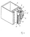
- the only partially reproduced in the drawing facade construction represents a so-called all-glass facade, in which insulating glass panes 1 are enclosed on a reproduced here in the form of a pillar substructure 2, wherein on the outer surface no fastening elements for the insulating glass pane 1 can be seen.
- the insulating glass panes 1 are peripherally provided at least in some areas with a groove 3, in which a support arm 4 of a glass holder 5 engages, wherein the glass holder 5 is fixed to a screw groove having a connection profile 6 of the substructure 2.
- the holding arm 4 of the glass holder 5 is pivotally connected to an attachment base 7 of the glass holder 5, so that the glass holder 5 can be mounted both before and after the attachment of the insulating glass panes 1, as shown in FIGS FIGS. 1 or 3 can be seen.
- the attachment base 7 itself has a substantially U-shaped connecting element 8, with which it is firmly seated on the connection profile 6. These are the two Leg of the connecting element 8 is provided on its inner surfaces with projecting ribs 9, which grip in a toothing 10 on the outer surfaces of the connection profile 6 by clamping.
- the attachment base 7 carries a bearing bush 11 on which the support arm 4 is rotatably supported by means of a socket 12.
- the bushing 11 is provided with detents 13, which engages behind an annular shoulder 14 on the inner circumferential surface of the socket 12. Further, the bearing bush 11 is formed by spring blades, which are spaced apart by axially extending cutouts 15, wherein the latching pawls 13 are arranged at the free ends of the spring blades. This makes it possible to easily push the socket 12 on the bearing bush 11, whereby the spring blades deform temporarily to then engage with their detents 13 behind the annular shoulder 14.
- the plug-in sleeve 12 is provided at its end face facing the attachment base 7 with sawtooth-shaped link projections 16, which are assigned in the attachment socket 7 correspondingly shaped link recesses 17.
- an axial movement stroke of the receptacle 12 is achieved with respect to the bearing bush 11, whereby it is possible to achieve a contact pressure of the insulating glass pane 1 against the substructure 2 during assembly of the glass holder 5.
- the slide projections 16 to the KulissenausEnglishept 17 be aligned so that they are in mutual engagement when the support arm 4 engages in the groove 3 of the insulating glass pane 1.
- the slide projections 16 are arranged uniformly distributed over the circumference.
- a stop bar 18 is further provided for an axially on the socket 12 extending stop rib 19, which serves to ensure during assembly of the glass holder 5 that the support arm 4 in optimal alignment, ie aligned perpendicular to the edge of the insulating glass pane 1 is to ensure maximum retention of the insulating glass pane 1.
- the glass holder 5 itself is secured by means of a self-tapping or furrowing, in the screw channel of the connection profile 6 cross-bolt 20, which extends coaxially in the socket 12.
- the socket 12 is for this purpose provided with a receptacle 21 in which the head of the screw 20 is supported.
- the arrangement of the screw 20 in the socket 12 can be made so that the socket 12 is taken when turning the screw 20 with Raibschluß, the support arms 4 so when turning the screw 20 automatically pivot into the groove 3.
- the plug-in sleeve 12 has two support arms 4 aligned in an aligned manner; If the glass holder 5 is arranged on the edge of a façade surface, however, the socket 12 carries only a support arm 4. To this case, the support arms 4, as in the FIGS. 2a and 2b arranged, spherically shaped at its free end.
Landscapes
- Engineering & Computer Science (AREA)
- Civil Engineering (AREA)
- Structural Engineering (AREA)
- Load-Bearing And Curtain Walls (AREA)
- Securing Of Glass Panes Or The Like (AREA)
- Roof Covering Using Slabs Or Stiff Sheets (AREA)
Abstract
Description
- Die Erfindung betrifft eine Fassaden- und/oder Lichtdachkonstruktion mit wenigstens einer an einer Unterkonstruktion festgelegten Isolierglasscheibe, die randseitig zumindest in Teilbereichen mit einer Nut versehen ist, in die ein Haltearm eines Glashalters eingreift, der an einem eine Schraubnut aufweisenden Anschlußprofil der Unterkonstruktion befestigt ist.
- Insbesondere bei sogenannten Ganzglasfassaden von Gebäuden werden Glashalter benötigt, die auf möglichst unauffällige Weise für eine Halterung der Isolierglasscheiben sorgen, wobei die Glashalter entweder bereits vor Anbringung der Isolierglasscheiben oder auch erst danach montiert werden.
- Aus dem Stand der Technik sind bereits derartige Konstruktionen bekannt, die sich jedoch dadurch auszeichnen, dass die Anbringung der Glashalter umständlich ist bzw. spezielle Werkzeuge erfordern, wodurch die Montage zusätzlich erschwert wird.
- Der Erfindung liegt daher die Aufgabe zugrunde, eine Fassaden- und/oder Lichtdachkonstruktion der eingangs genannten Art derart weiterzuentwickeln, dass sowohl die Montage des Glashalters als auch die anschließende Befestigung der Isolierglaselemente auf einfache Weise und insbesondere mit üblichem Werkzeug erfolgen kann.
- Diese Aufgabe wird nach der Erfindung dadurch gelöst, dass der Haltearm an einem Aufsatzsockel des Glashalters schwenkbar angeschlossen ist, wobei der Aufsatzsockel ein im wesentlichen U-förmiges Anschlußelement aufweist und mit diesem auf das Anschlußprofil fest aufgesetzt ist.
- Der durch die Erfindung erreichte Vorteil besteht im wesentlichen darin, dass der Glashalter zunächst am Anschlußprofil befestigt werden kann und anschließend durch den schwenkbar ausgebildeten Haltearm die eigentliche Fixierung der Isolierglasscheibe erfolgen kann.
- Um die Anbringung des Glashalters am Anschlußprofil besonders einfach zu gestalten, wird im Rahmen der Erfindung vorgeschlagen, dass die beiden Schenkel des Anschlußelements an ihren Innenflächen mit vorstehenden Rippen versehen sind, die klemmend in eine Verzahnung an den Außenflächen des Anschlußprofils greifen.
- Weiter hat es sich im Rahmen der Erfindung als vorteilhaft erwiesen, wenn der Aufsatzsockel eine Lagerbuchse trägt, auf der der Haltearm mittels einer Steckhülse drehbar gelagert ist. Hierdurch wird auf einfache Weise das Verschwenken des Haltearms ermöglicht.
- Von besonderem Vorteil ist es hierbei, wenn die Lagerbuchse mit Rastklinken versehen ist, die eine Ringschulter an der Innenmantelfläche der Steckhülse hintergreift. Auf diese Art und Weise läßt sich der Glashalter besonders einfach zusammensetzen, wobei darüber hinaus sogar die Möglichkeit besteht, zunächst nur den Aufsatzsockel des Glashalters zu montieren, um anschließend erst den Haltearm mit der Steckhülse auf die Lagerbuchse aufzusetzen.
- Hierzu ist es weiter von Vorteil, wenn die Lagerbuchse von Federlamellen gebildet ist, die durch axial verlaufende Freischneidungen voneinander beabstandet sind, wobei die Rastklinken an den freien Enden der Federlamellen angeordnet sind.
- Weiter wird im Rahmen der Erfindung vorgeschlagen, dass die Steckhülse an ihrer zum Aufsatzsockel weisenden Stirnfläche mit sägezahnförmigen Kulissenvorsprüngen versehen sind, denen im Aufsatzsockel entsprechend geformte Kulissenausnehmungen zugeordnet sind, wobei die Kulissenvorsprünge zu den Kulissenausnehmungen so ausgerichtet sind, dass sie in gegenseitigen Eingriff sind, wenn der Haltearm in die Nut der Isolierglasscheibe greift. Hierdurch wird erreicht, dass bei Drehung der Steckhülse mit den Haltearmen diese in Richtung zur Unterkonstruktion hin verlagert werden, wodurch die Isolierglasscheiben eine Anpresskraft ebenfalls in Richtung zur Unterkonstruktion erfahren.
- Die Kulissenvorsprünge sind hierbei vorteilhafterweise gleichmäßig verteilt über den Umfang angeordnet.
- Um eine genaue Ausrichtung der Haltearme nach Befestigung der Isolierglasscheiben sicherzustellen, hat es sich als zweckmäßig erwiesen, wenn am Aufsatzsockel eine Anschlagleiste für eine axial an der Steckhülse verlaufende Anschlagrippe vorgesehen ist. Somit kann sich die Steckhülse nur soweit auf dem Aufsatzsockel verdrehen, bis der Haltearm im wesentlichen senkrecht zum Rand der Isolierglasscheibe ausgerichtet ist.
- Der Glashalter selbst wird zweckmäßigerweise mittels einer selbstschneidenden oder- furchenden, in den Schraubkanal greifenden und koaxial in der Steckhülse verlaufenden Schraube am Anschlußprofil gesichert, die sich mit ihrem Kopf in einer Aufnahme der Steckhülse abstützt.
- Die Steckhülse kann entweder einen Haltearm oder aber zwei gestreckt zueinander ausgerichtete Haltearme aufweisen, je nachdem, ob sie mitten in einem Feld von Isolierglasscheiben oder an deren Rand angebracht wird.
- Um definierte Andruckkräfte zu erreichen, ist es weiter von Vorteil, wenn die Haltearme an ihrem freien Ende ballig geformt sind.
- Im folgenden wird die Erfindung an einem in der Zeichnung dargestellten Ausführungsbeispiel näher erläutert; es zeigen:
- Fig. 1
- eine perspektivische Darstellung einer Fassadenkonstruktion, nur teilweise wiedergegeben,
- Fig. 2
- in den Teilfiguren a bis c den Glashalter in noch nicht zusammengesetztem Zustand,
- Fig. 3
- eine der
Figur 1 entsprechende Darstellung, jedoch ohne Isolierglasscheiben und bei aufgesetztem Glashalter. - Die in der Zeichnung nur teilweise wiedergegebene Fassadenkonstruktion stellt eine sogenannte Ganzglasfassade dar, bei welcher Isolierglasscheiben 1 an einer hier in Form eines Pfostens wiedergebenen Unterkonstruktion 2 eingeschlossen sind, wobei an der Außenfläche keine Befestigungselemente für die Isolierglasscheibe 1 zu sehen sind. Dazu sind die Isolierglasscheiben 1 randseitig zumindest in Teilbereichen mit einer Nut 3 versehen, in die ein Haltearm 4 eines Glashalters 5 eingreift, wobei der Glashalter 5 an einem eine Schraubnut aufweisenden Anschlußprofil 6 der Unterkonstruktion 2 befestigt ist.
- Im einzelnen ist der Haltearm 4 des Glashalters 5 an einem Aufsatzsockel 7 des Glashalters 5 schwenkbar angeschlossen, so dass der Glashalter 5 sowohl vor als auch nach der Anbringung der Isolierglasscheiben 1 montiert werden kann, wie dies aus den
Figuren 1 bzw. 3 zu ersehen ist. - Der Aufsatzsockel 7 selbst weist ein im wesentlichen U-förmiges Anschlußelement 8 auf, mit welchem er auf das Anschlußprofil 6 fest aufgesetzt ist. Dazu sind die beiden Schenkel des Anschlußelements 8 an ihren Innenflächen mit vorstehenden Rippen 9 versehen, die klemmend in eine Verzahnung 10 an den Außenflächen des Anschlußprofils 6 greifen.
- Wie sich insbesondere aus der
Figur 2 ersehen läßt, trägt der Aufsatzsockel 7 eine Lagerbuchse 11, auf der der Haltearm 4 mittels einer Steckhülse 12 drehbar gelagert ist. - Die Lagerbuchse 11 ist mit Rastklinken 13 versehen, die eine Ringschulter 14 an der Innenmantelfläche der Steckhülse 12 hintergreift. Weiter ist die Lagerbuchse 11 von Federlamellen gebildet, die durch axial verlaufende Freischneidungen 15 voneinander beabstandet sind, wobei die Rastklinken 13 an den freien Enden der Federlamellen angeordnet sind. Hierdurch besteht die Möglichkeit, die Steckhülse 12 einfach auf die Lagerbuchse 11 aufzuschieben, wodurch sich die Federlamellen vorübergehend verformen, um anschließend mit ihren Rastklinken 13 hinter der Ringschulter 14 einzugreifen.
- Wie sich weiter aus der
Figur 2 ersehen läßt, ist die Steckhülse 12 an ihrer zum Aufsatzsockel 7 weisenden Stirnfläche mit sägezahnförmigen Kulissenvorsprüngen 16 versehen, denen im Aufsatzsockel 7 entsprechend geformte Kulissenausnehmungen 17 zugeordnet sind. Durch diese Kulissenvorsprünge 16 bzw. Kulissenausnehmungen 17 wird ein axialer Bewegungshub der Steckhülse 12 gegenüber der Lagerbuchse 11 erreicht, wodurch es möglich ist, bei der Montage des Glashalters 5 eine Anpresskraft der Isolierglasscheibe 1 gegen die Unterkonstruktion 2 zu erreichen. Hierzu müssen die Kulissenvorsprünge 16 zu den Kulissenausnehmungen 17 so ausgerichtet sein, dass sie in gegenseitigem Eingriff sind, wenn der Haltearm 4 in die Nut 3 der Isolierglasscheibe 1 greift. - Wie sich weiter aus der Zeichnung ersehen läßt sind die Kulissenvorsprünge 16 hierbei gleichmäßig verteilt über den Umfang angeordnet.
- Am Aufsatzsockel 7 ist weiter eine Anschlagleiste 18 für eine axial an der Steckhülse 12 verlaufende Anschlagrippe 19 vorgesehen, die dazu dient, bei der Montage des Glashalters 5 dafür zu sorgen, dass der Haltearm 4 in optimaler Ausrichtung, also senkrecht zum Rand der Isolierglasscheibe 1 ausgerichtet ist, um maximalen Halt der Isolierglasscheibe 1 zu gewährleisten.
- Der Glashalter 5 selbst wird mittels einer selbstschneidenden oder- furchenden, in den Schraubkanal des Anschlußprofils 6 greifenden Schraube 20 gesichert, die koaxial in der Steckhülse 12 verläuft. Die Steckhülse 12 ist hierzu mit einer Aufnahme 21 versehen, in der sich der Kopf der Schraube 20 abstützt. Die Anordnung der Schraube 20 in der Steckhülse 12 kann dabei so erfolgen, dass die Steckhülse 12 beim Drehen der Schraube 20 unter Raibschluß mitgenommen wird, die Haltearme 4 also beim Eindrehen der Schraube 20 selbsttätig in die Nut 3 einschwenken.
- Bei dem in der Zeichnung dargestellten Ausführungsbeispiel weist die Steckhülse 12 zwei gestreckt zueinander ausgerichtete Haltearme 4 auf; sofern der Glashalter 5 am Rand einer Fassadenfläche angeordnet wird, trägt die Steckhülse 12 dagegen nur einen Haltearm 4. Um hierbei definierte Andruckkraft sicher zu stellen, sind die Haltearme 4, wie in den
Figuren 2a und 2b angeordnet, an ihrem freien Ende ballig geformt.
Claims (11)
- Fassaden- und/oder Lichtdachkonstruktion mit wenigstens einer an einer Unterkonstruktion (2) festgelegten Isolierglasscheibe (1), die randseitig zumindest in Teilbereichen mit einer Nut (3) versehen ist, in die ein Haltearm (4) eines Glashalters (5) eingreift, der an einem eine Schraubnut aufweisenden Anschlußprofil (6) der Unterkonstruktion (2) befestigt ist, dadurch gekennzeichnet, daß der Haltearm (4) an einem Aufsatzsockel (7) des Glashalters (5) schwenkbar angeschlossen ist, wobei der Aufsatzsockel (7) ein im wesentlichen U-förmiges Anschlußelement (8) aufweist und mit diesem auf das Anschlußprofil (6) fest aufgesetzt ist.
- Fassaden- und/oder Lichtdachkonstruktion nach Anspruch 1, dadurch gekennzeichnet, daß die beiden Schenkel des Anschlußelements (8) an ihren Innenflächen mit vorstehenden Rippen (9) versehen sind, die klemmend in eine Verzahnung (10) an den Außenflächen des Anschlußprofils (6) greifen.
- Fassaden- und/oder Lichtdachkonstruktion nach Anspruch 1 oder 2, dadurch gekennzeichnet, daß der Aufsatzsockel (7) eine Lagerbuchse (11) trägt, auf der der Haltearm (4) mittels einer Steckhülse (12) drehbar gelagert ist.
- Fassaden- und/oder Lichtdachkonstruktion nach Anspruch 3, dadurch gekennzeichnet, daß die Lagerbuchse (11) mit Rastklinken (13) versehen ist, die eine Ringschulter (14) an der Innenmantelfläche der Steckhülse (12) hintergreift.
- Fassaden- und/oder Lichtdachkonstruktion nach Anspruch 3 oder 4, dadurch gekennzeichnet, daß die Lagerbuchse (11) von Federlamellen gebildet ist, die durch axial verlaufende Freischneidungen (15) voneinander beabstandet sind, wobei die Rastklinken (13) an den freien Enden der Federlamellen angeordnet sind.
- Fassaden- und/oder Lichtdachkonstruktion nach einem der Ansprüche 3 bis 5, dadurch gekennzeichnet, daß die Steckhülse (12) an ihrer zum Aufsatzsockel (7) weisenden Stirnfläche mit sägezahnförmigen Kulissenvorsprüngen (16) versehen ist, denen im Aufsatzsockel (7) entsprechend geformte Kulissenausnehmungen (17) zugeordnet sind, wobei die Kulissenvorsprünge (16) zu den Kulissenausnehmungen (17) so ausgerichtet sind, daß sie im gegenseitigen Eingriff sind, wenn der Haltearm (4) in die Nut (3) der Isolierglasscheibe (1) greift.
- Fassaden- und/oder Lichtdachkonstruktion nach Anspruch 6, dadurch gekennzeichnet, daß die Kulissenvorsprünge (16) gleichmäßig verteilt über den Umfang angeordnet sind.
- Fassaden- und/oder Lichtdachkonstruktion nach einem der Ansprüche 3 bis 7, dadurch gekennzeichnet, daß am Aufsatzsockel (7) eine Anschlagleiste (18) für eine axial an der Steckhülse (12) verlaufende Anschlagrippe (19) vorgesehen ist.
- Fassaden- und/oder Lichtdachkonstruktion nach einem der Ansprüche 3 bis 8, dadurch gekennzeichnet, daß der Glashalter (5) mittels einer selbstschneidenden oder -furchenden, in die Schraubnut des Anschlußprofils (6) greifenden und koaxial in der Steckhülse (12) verlaufenden Schraube (20) am Anschlußprofil (6) gesichert ist, die sich mit ihrem Kopf in einer Aufnahme (21) der Steckhülse (12) abstützt.
- Fassaden- und/oder Lichtdachkonstruktion nach einem der Ansprüche 1 bis 8, dadurch gekennzeichnet, daß die Steckhülse (12) einen Haltearm (4) oder zwei gestreckt zueinander ausgerichtete Haltearme (4) aufweist.
- Fassaden- und/oder Lichtdachkonstruktion nach einem der Ansprüche 1 bis 8, dadurch gekennzeichnet, daß die Haltearme (4) an ihrem freien Ende ballig geformt sind.
Applications Claiming Priority (1)
| Application Number | Priority Date | Filing Date | Title |
|---|---|---|---|
| DE102007012854A DE102007012854A1 (de) | 2007-03-17 | 2007-03-17 | Fassaden- und/oder Lichtdachkonstruktion |
Publications (3)
| Publication Number | Publication Date |
|---|---|
| EP1972748A2 true EP1972748A2 (de) | 2008-09-24 |
| EP1972748A3 EP1972748A3 (de) | 2010-09-15 |
| EP1972748B1 EP1972748B1 (de) | 2011-05-11 |
Family
ID=39494712
Family Applications (1)
| Application Number | Title | Priority Date | Filing Date |
|---|---|---|---|
| EP08004464A Not-in-force EP1972748B1 (de) | 2007-03-17 | 2008-03-11 | Fassaden-und/oder Lichtdachkonstruktion |
Country Status (4)
| Country | Link |
|---|---|
| EP (1) | EP1972748B1 (de) |
| AT (1) | ATE509176T1 (de) |
| DE (1) | DE102007012854A1 (de) |
| ES (1) | ES2366301T3 (de) |
Cited By (5)
| Publication number | Priority date | Publication date | Assignee | Title |
|---|---|---|---|---|
| WO2009113889A1 (en) * | 2008-03-10 | 2009-09-17 | Fakro Pp Spolka Z O. O. | Covering slat with fastening bar |
| FR2938595A1 (fr) * | 2008-11-20 | 2010-05-21 | Norsk Hydro As | Systeme d'assemblage de trois corps entre eux pour former une piece sensiblement en forme de "t" et application aux murs-rideaux |
| FR2938596A1 (fr) * | 2008-11-20 | 2010-05-21 | Norsk Hydro As | Systeme d'assemblage de trois corps entre eux pour former une piece sensiblement en forme de "t" et application aux murs-rideaux |
| ITMI20090807A1 (it) * | 2009-05-12 | 2010-11-13 | Gastaldello Sistemi S P A | Elemento per il bloccaggio di un elemento lastriforme ad un profilo longitudinale di una facciata continua |
| ITGO20090009A1 (it) * | 2009-11-04 | 2011-05-05 | Carmen Gasparotto | Dispositivo per il fissaggio di vetri doppi in particolare su facciate continue |
Families Citing this family (1)
| Publication number | Priority date | Publication date | Assignee | Title |
|---|---|---|---|---|
| FR3108926B1 (fr) * | 2020-04-03 | 2022-05-27 | Kernex Sas | Module de façade et façade de bâtiment associée |
Family Cites Families (7)
| Publication number | Priority date | Publication date | Assignee | Title |
|---|---|---|---|---|
| SE501974C2 (sv) * | 1993-11-10 | 1995-07-03 | Scandinavian Licence Ab | Glasningssystem för byggnader |
| DE69924602T2 (de) * | 1998-01-19 | 2006-03-02 | Kenny, Simon Joseph, Tullow | Verglasungssystem |
| DE29915574U1 (de) * | 1999-09-04 | 2001-01-18 | Raico Bautechnik GmbH, 87746 Erkheim | Fassade mit Adapterprofil |
| DE19942170A1 (de) * | 1999-09-04 | 2001-03-08 | Raico Bautechnik Gmbh | Fassade mit Befestigungsvorrichtung |
| NL1016724C2 (nl) * | 2000-11-28 | 2002-05-29 | Reynolds Architectuursystemen | Vliesgevel en werkwijze voor de vervaardiging daarvan. |
| GB2373002B (en) * | 2001-03-09 | 2004-04-07 | Levolux At Ltd | Apparatus for and a method of attaching items to curtain walling |
| EP1581715B1 (de) * | 2003-01-08 | 2017-01-11 | SCHÜCO International KG | Fassaden- und/oder lichtdachkonstrution |
-
2007
- 2007-03-17 DE DE102007012854A patent/DE102007012854A1/de not_active Withdrawn
-
2008
- 2008-03-11 EP EP08004464A patent/EP1972748B1/de not_active Not-in-force
- 2008-03-11 AT AT08004464T patent/ATE509176T1/de active
- 2008-03-11 ES ES08004464T patent/ES2366301T3/es active Active
Cited By (7)
| Publication number | Priority date | Publication date | Assignee | Title |
|---|---|---|---|---|
| WO2009113889A1 (en) * | 2008-03-10 | 2009-09-17 | Fakro Pp Spolka Z O. O. | Covering slat with fastening bar |
| FR2938595A1 (fr) * | 2008-11-20 | 2010-05-21 | Norsk Hydro As | Systeme d'assemblage de trois corps entre eux pour former une piece sensiblement en forme de "t" et application aux murs-rideaux |
| FR2938596A1 (fr) * | 2008-11-20 | 2010-05-21 | Norsk Hydro As | Systeme d'assemblage de trois corps entre eux pour former une piece sensiblement en forme de "t" et application aux murs-rideaux |
| EP2189611A1 (de) | 2008-11-20 | 2010-05-26 | Norsk Hydro Asa | Montagesystem von drei Körpern untereinander, um ein Teil mit deutlicher T-Form zu bilden, und Anwendung auf Vorhangfassaden |
| EP2189610A1 (de) | 2008-11-20 | 2010-05-26 | Norsk Hydro ASA | Befestigungsvorrichtung für eine Vorhangwand |
| ITMI20090807A1 (it) * | 2009-05-12 | 2010-11-13 | Gastaldello Sistemi S P A | Elemento per il bloccaggio di un elemento lastriforme ad un profilo longitudinale di una facciata continua |
| ITGO20090009A1 (it) * | 2009-11-04 | 2011-05-05 | Carmen Gasparotto | Dispositivo per il fissaggio di vetri doppi in particolare su facciate continue |
Also Published As
| Publication number | Publication date |
|---|---|
| ATE509176T1 (de) | 2011-05-15 |
| EP1972748B1 (de) | 2011-05-11 |
| ES2366301T3 (es) | 2011-10-19 |
| DE102007012854A1 (de) | 2008-09-18 |
| EP1972748A3 (de) | 2010-09-15 |
Similar Documents
| Publication | Publication Date | Title |
|---|---|---|
| EP1972748B1 (de) | Fassaden-und/oder Lichtdachkonstruktion | |
| EP3345257B1 (de) | Halterahmen für steckverbindermodule | |
| DE2309398C3 (de) | Anordnung für die Axialhalterung eines homokinetischen Gelenks | |
| EP2842446A1 (de) | Schwenkbarer Sonnenschirm | |
| DE2718170B2 (de) | Befestigungsclip fur verkleidete Abdeckplatten, insbesondere fur Kraftfahrzeuge | |
| DE3420528A1 (de) | Stufenlos verstellbare hubvorrichtung | |
| DE10051805A1 (de) | WC-Sitzgelenk | |
| EP0859090A1 (de) | Gleitstück für Brausewandstange | |
| EP2194335A1 (de) | Befestigungssystem für einen solartechnischen Kollektor | |
| DE19908259A1 (de) | Wischmopplatte mit Schwenkkarretiereinrichtung | |
| DE202015004818U1 (de) | Ein multifunktionales Leuchten für Garten -und Strandschirme | |
| DE19942170A1 (de) | Fassade mit Befestigungsvorrichtung | |
| EP1900899A2 (de) | Befestigungsvorrichtung für Aufsatzelemente, insbesondere Insekten-/Partikelschutzgitter | |
| EP1222406A1 (de) | Halter für kopfschrauben | |
| DE29713507U1 (de) | Befestigungsvorrichtung für einen zur Wandmontage von sanitären Elementen verwendeten Anschlußfitting | |
| EP2059371A2 (de) | Schere mit integriertem kabelschneider | |
| DE3228674A1 (de) | Gasfeder mit schnellmontageanschluss | |
| DE10295692B3 (de) | Teleskop-Federeinheit mit einer Feststelleinrichtung | |
| DE202016007363U1 (de) | Schwenkbarer Inbusschlüssel | |
| EP3759303B1 (de) | Montagehalter für führungsschienen | |
| DE102021125772B4 (de) | Abstandhalter, Führungsschiene für einen Raffstore oder eine Jalousie sowie Raffstore und Jalousie und Verfahren hierfür | |
| DE102015122791A1 (de) | Profilschiene mit Griffelement | |
| DE8111079U1 (de) | Ecklager fuer fluegel von fenstern, tueren od. dgl. | |
| DE4304587A1 (de) | Reflektorverstellung für eine Leuchte mit rotationssymmetrischem Reflektor | |
| DE102020126347B3 (de) | Abstandhalter, Führungsschiene für einen Raffstore oder eine Jalousie sowie Raffstore und Jalousie und Verfahren hierfür |
Legal Events
| Date | Code | Title | Description |
|---|---|---|---|
| PUAI | Public reference made under article 153(3) epc to a published international application that has entered the european phase |
Free format text: ORIGINAL CODE: 0009012 |
|
| AK | Designated contracting states |
Kind code of ref document: A2 Designated state(s): AT BE BG CH CY CZ DE DK EE ES FI FR GB GR HR HU IE IS IT LI LT LU LV MC MT NL NO PL PT RO SE SI SK TR |
|
| AX | Request for extension of the european patent |
Extension state: AL BA MK RS |
|
| PUAL | Search report despatched |
Free format text: ORIGINAL CODE: 0009013 |
|
| AK | Designated contracting states |
Kind code of ref document: A3 Designated state(s): AT BE BG CH CY CZ DE DK EE ES FI FR GB GR HR HU IE IS IT LI LT LU LV MC MT NL NO PL PT RO SE SI SK TR |
|
| AX | Request for extension of the european patent |
Extension state: AL BA MK RS |
|
| RIC1 | Information provided on ipc code assigned before grant |
Ipc: E06B 1/38 20060101ALI20100806BHEP Ipc: E06B 3/54 20060101AFI20080618BHEP Ipc: E04B 2/88 20060101ALI20100806BHEP Ipc: E06B 1/36 20060101ALI20100806BHEP Ipc: E04D 3/08 20060101ALI20100806BHEP |
|
| 17P | Request for examination filed |
Effective date: 20100915 |
|
| GRAP | Despatch of communication of intention to grant a patent |
Free format text: ORIGINAL CODE: EPIDOSNIGR1 |
|
| RIC1 | Information provided on ipc code assigned before grant |
Ipc: E04D 3/08 20060101ALI20101028BHEP Ipc: E06B 1/36 20060101ALI20101028BHEP Ipc: E06B 1/38 20060101ALI20101028BHEP Ipc: E04B 2/88 20060101ALI20101028BHEP Ipc: E06B 3/54 20060101AFI20101028BHEP |
|
| GRAS | Grant fee paid |
Free format text: ORIGINAL CODE: EPIDOSNIGR3 |
|
| GRAA | (expected) grant |
Free format text: ORIGINAL CODE: 0009210 |
|
| AK | Designated contracting states |
Kind code of ref document: B1 Designated state(s): AT BE BG CH CY CZ DE DK EE ES FI FR GB GR HR HU IE IS IT LI LT LU LV MC MT NL NO PL PT RO SE SI SK TR |
|
| REG | Reference to a national code |
Ref country code: GB Ref legal event code: FG4D Free format text: NOT ENGLISH |
|
| REG | Reference to a national code |
Ref country code: CH Ref legal event code: EP |
|
| REG | Reference to a national code |
Ref country code: IE Ref legal event code: FG4D |
|
| REG | Reference to a national code |
Ref country code: DE Ref legal event code: R096 Ref document number: 502008003468 Country of ref document: DE Effective date: 20110622 |
|
| REG | Reference to a national code |
Ref country code: NL Ref legal event code: VDEP Effective date: 20110511 |
|
| REG | Reference to a national code |
Ref country code: ES Ref legal event code: FG2A Ref document number: 2366301 Country of ref document: ES Kind code of ref document: T3 Effective date: 20111019 |
|
| PG25 | Lapsed in a contracting state [announced via postgrant information from national office to epo] |
Ref country code: NO Free format text: LAPSE BECAUSE OF FAILURE TO SUBMIT A TRANSLATION OF THE DESCRIPTION OR TO PAY THE FEE WITHIN THE PRESCRIBED TIME-LIMIT Effective date: 20110811 Ref country code: LT Free format text: LAPSE BECAUSE OF FAILURE TO SUBMIT A TRANSLATION OF THE DESCRIPTION OR TO PAY THE FEE WITHIN THE PRESCRIBED TIME-LIMIT Effective date: 20110511 Ref country code: HR Free format text: LAPSE BECAUSE OF FAILURE TO SUBMIT A TRANSLATION OF THE DESCRIPTION OR TO PAY THE FEE WITHIN THE PRESCRIBED TIME-LIMIT Effective date: 20110518 Ref country code: SE Free format text: LAPSE BECAUSE OF FAILURE TO SUBMIT A TRANSLATION OF THE DESCRIPTION OR TO PAY THE FEE WITHIN THE PRESCRIBED TIME-LIMIT Effective date: 20110511 Ref country code: PT Free format text: LAPSE BECAUSE OF FAILURE TO SUBMIT A TRANSLATION OF THE DESCRIPTION OR TO PAY THE FEE WITHIN THE PRESCRIBED TIME-LIMIT Effective date: 20110912 |
|
| PG25 | Lapsed in a contracting state [announced via postgrant information from national office to epo] |
Ref country code: GR Free format text: LAPSE BECAUSE OF FAILURE TO SUBMIT A TRANSLATION OF THE DESCRIPTION OR TO PAY THE FEE WITHIN THE PRESCRIBED TIME-LIMIT Effective date: 20110812 Ref country code: IS Free format text: LAPSE BECAUSE OF FAILURE TO SUBMIT A TRANSLATION OF THE DESCRIPTION OR TO PAY THE FEE WITHIN THE PRESCRIBED TIME-LIMIT Effective date: 20110911 Ref country code: LV Free format text: LAPSE BECAUSE OF FAILURE TO SUBMIT A TRANSLATION OF THE DESCRIPTION OR TO PAY THE FEE WITHIN THE PRESCRIBED TIME-LIMIT Effective date: 20110511 Ref country code: FI Free format text: LAPSE BECAUSE OF FAILURE TO SUBMIT A TRANSLATION OF THE DESCRIPTION OR TO PAY THE FEE WITHIN THE PRESCRIBED TIME-LIMIT Effective date: 20110511 Ref country code: SI Free format text: LAPSE BECAUSE OF FAILURE TO SUBMIT A TRANSLATION OF THE DESCRIPTION OR TO PAY THE FEE WITHIN THE PRESCRIBED TIME-LIMIT Effective date: 20110511 Ref country code: CY Free format text: LAPSE BECAUSE OF FAILURE TO SUBMIT A TRANSLATION OF THE DESCRIPTION OR TO PAY THE FEE WITHIN THE PRESCRIBED TIME-LIMIT Effective date: 20110511 |
|
| REG | Reference to a national code |
Ref country code: IE Ref legal event code: FD4D |
|
| PG25 | Lapsed in a contracting state [announced via postgrant information from national office to epo] |
Ref country code: NL Free format text: LAPSE BECAUSE OF FAILURE TO SUBMIT A TRANSLATION OF THE DESCRIPTION OR TO PAY THE FEE WITHIN THE PRESCRIBED TIME-LIMIT Effective date: 20110511 |
|
| PG25 | Lapsed in a contracting state [announced via postgrant information from national office to epo] |
Ref country code: EE Free format text: LAPSE BECAUSE OF FAILURE TO SUBMIT A TRANSLATION OF THE DESCRIPTION OR TO PAY THE FEE WITHIN THE PRESCRIBED TIME-LIMIT Effective date: 20110511 Ref country code: CZ Free format text: LAPSE BECAUSE OF FAILURE TO SUBMIT A TRANSLATION OF THE DESCRIPTION OR TO PAY THE FEE WITHIN THE PRESCRIBED TIME-LIMIT Effective date: 20110511 Ref country code: IE Free format text: LAPSE BECAUSE OF FAILURE TO SUBMIT A TRANSLATION OF THE DESCRIPTION OR TO PAY THE FEE WITHIN THE PRESCRIBED TIME-LIMIT Effective date: 20110511 |
|
| PG25 | Lapsed in a contracting state [announced via postgrant information from national office to epo] |
Ref country code: SK Free format text: LAPSE BECAUSE OF FAILURE TO SUBMIT A TRANSLATION OF THE DESCRIPTION OR TO PAY THE FEE WITHIN THE PRESCRIBED TIME-LIMIT Effective date: 20110511 Ref country code: RO Free format text: LAPSE BECAUSE OF FAILURE TO SUBMIT A TRANSLATION OF THE DESCRIPTION OR TO PAY THE FEE WITHIN THE PRESCRIBED TIME-LIMIT Effective date: 20110511 Ref country code: PL Free format text: LAPSE BECAUSE OF FAILURE TO SUBMIT A TRANSLATION OF THE DESCRIPTION OR TO PAY THE FEE WITHIN THE PRESCRIBED TIME-LIMIT Effective date: 20110511 Ref country code: DK Free format text: LAPSE BECAUSE OF FAILURE TO SUBMIT A TRANSLATION OF THE DESCRIPTION OR TO PAY THE FEE WITHIN THE PRESCRIBED TIME-LIMIT Effective date: 20110511 |
|
| PLBE | No opposition filed within time limit |
Free format text: ORIGINAL CODE: 0009261 |
|
| STAA | Information on the status of an ep patent application or granted ep patent |
Free format text: STATUS: NO OPPOSITION FILED WITHIN TIME LIMIT |
|
| 26N | No opposition filed |
Effective date: 20120214 |
|
| REG | Reference to a national code |
Ref country code: DE Ref legal event code: R097 Ref document number: 502008003468 Country of ref document: DE Effective date: 20120214 |
|
| PG25 | Lapsed in a contracting state [announced via postgrant information from national office to epo] |
Ref country code: MC Free format text: LAPSE BECAUSE OF NON-PAYMENT OF DUE FEES Effective date: 20120331 |
|
| REG | Reference to a national code |
Ref country code: CH Ref legal event code: PL |
|
| PG25 | Lapsed in a contracting state [announced via postgrant information from national office to epo] |
Ref country code: CH Free format text: LAPSE BECAUSE OF NON-PAYMENT OF DUE FEES Effective date: 20120331 Ref country code: LI Free format text: LAPSE BECAUSE OF NON-PAYMENT OF DUE FEES Effective date: 20120331 |
|
| PG25 | Lapsed in a contracting state [announced via postgrant information from national office to epo] |
Ref country code: BG Free format text: LAPSE BECAUSE OF FAILURE TO SUBMIT A TRANSLATION OF THE DESCRIPTION OR TO PAY THE FEE WITHIN THE PRESCRIBED TIME-LIMIT Effective date: 20110811 |
|
| PG25 | Lapsed in a contracting state [announced via postgrant information from national office to epo] |
Ref country code: MT Free format text: LAPSE BECAUSE OF FAILURE TO SUBMIT A TRANSLATION OF THE DESCRIPTION OR TO PAY THE FEE WITHIN THE PRESCRIBED TIME-LIMIT Effective date: 20110511 |
|
| PG25 | Lapsed in a contracting state [announced via postgrant information from national office to epo] |
Ref country code: HR Free format text: LAPSE BECAUSE OF FAILURE TO SUBMIT A TRANSLATION OF THE DESCRIPTION OR TO PAY THE FEE WITHIN THE PRESCRIBED TIME-LIMIT Effective date: 20110511 |
|
| PG25 | Lapsed in a contracting state [announced via postgrant information from national office to epo] |
Ref country code: TR Free format text: LAPSE BECAUSE OF FAILURE TO SUBMIT A TRANSLATION OF THE DESCRIPTION OR TO PAY THE FEE WITHIN THE PRESCRIBED TIME-LIMIT Effective date: 20110511 |
|
| PG25 | Lapsed in a contracting state [announced via postgrant information from national office to epo] |
Ref country code: LU Free format text: LAPSE BECAUSE OF NON-PAYMENT OF DUE FEES Effective date: 20120311 |
|
| PG25 | Lapsed in a contracting state [announced via postgrant information from national office to epo] |
Ref country code: HU Free format text: LAPSE BECAUSE OF FAILURE TO SUBMIT A TRANSLATION OF THE DESCRIPTION OR TO PAY THE FEE WITHIN THE PRESCRIBED TIME-LIMIT Effective date: 20080311 |
|
| REG | Reference to a national code |
Ref country code: GB Ref legal event code: 732E Free format text: REGISTERED BETWEEN 20141023 AND 20141029 |
|
| REG | Reference to a national code |
Ref country code: FR Ref legal event code: TP Owner name: SAPA AS, NO Effective date: 20141124 |
|
| REG | Reference to a national code |
Ref country code: DE Ref legal event code: R082 Ref document number: 502008003468 Country of ref document: DE Representative=s name: PATENTANWAELTE FAY & DZIEWIOR, DE |
|
| REG | Reference to a national code |
Ref country code: DE Ref legal event code: R082 Ref document number: 502008003468 Country of ref document: DE Representative=s name: PATENTANWAELTE FAY & DZIEWIOR, DE Effective date: 20150105 Ref country code: DE Ref legal event code: R081 Ref document number: 502008003468 Country of ref document: DE Owner name: SAPA AS, NO Free format text: FORMER OWNER: HYDRO ALUMINIUM AS, OSLO, NO Effective date: 20150105 |
|
| REG | Reference to a national code |
Ref country code: ES Ref legal event code: PC2A Owner name: SAPA AS Effective date: 20150226 |
|
| REG | Reference to a national code |
Ref country code: AT Ref legal event code: PC Ref document number: 509176 Country of ref document: AT Kind code of ref document: T Owner name: SAPA AS, NO Effective date: 20150820 |
|
| REG | Reference to a national code |
Ref country code: FR Ref legal event code: PLFP Year of fee payment: 9 |
|
| REG | Reference to a national code |
Ref country code: FR Ref legal event code: PLFP Year of fee payment: 10 |
|
| REG | Reference to a national code |
Ref country code: FR Ref legal event code: PLFP Year of fee payment: 11 |
|
| REG | Reference to a national code |
Ref country code: DE Ref legal event code: R082 Ref document number: 502008003468 Country of ref document: DE Representative=s name: EISENFUEHR SPEISER PATENTANWAELTE RECHTSANWAEL, DE |
|
| PGFP | Annual fee paid to national office [announced via postgrant information from national office to epo] |
Ref country code: FR Payment date: 20230222 Year of fee payment: 16 Ref country code: AT Payment date: 20230224 Year of fee payment: 16 |
|
| PGFP | Annual fee paid to national office [announced via postgrant information from national office to epo] |
Ref country code: IT Payment date: 20230206 Year of fee payment: 16 Ref country code: GB Payment date: 20230203 Year of fee payment: 16 Ref country code: DE Payment date: 20230202 Year of fee payment: 16 Ref country code: BE Payment date: 20230203 Year of fee payment: 16 |
|
| PGFP | Annual fee paid to national office [announced via postgrant information from national office to epo] |
Ref country code: ES Payment date: 20230517 Year of fee payment: 16 |
|
| REG | Reference to a national code |
Ref country code: DE Ref legal event code: R119 Ref document number: 502008003468 Country of ref document: DE |
|
| REG | Reference to a national code |
Ref country code: AT Ref legal event code: MM01 Ref document number: 509176 Country of ref document: AT Kind code of ref document: T Effective date: 20240311 |
|
| GBPC | Gb: european patent ceased through non-payment of renewal fee |
Effective date: 20240311 |
|
| REG | Reference to a national code |
Ref country code: BE Ref legal event code: MM Effective date: 20240331 |
|
| PG25 | Lapsed in a contracting state [announced via postgrant information from national office to epo] |
Ref country code: DE Free format text: LAPSE BECAUSE OF NON-PAYMENT OF DUE FEES Effective date: 20241001 |
|
| PG25 | Lapsed in a contracting state [announced via postgrant information from national office to epo] |
Ref country code: BE Free format text: LAPSE BECAUSE OF NON-PAYMENT OF DUE FEES Effective date: 20240331 |
|
| PG25 | Lapsed in a contracting state [announced via postgrant information from national office to epo] |
Ref country code: GB Free format text: LAPSE BECAUSE OF NON-PAYMENT OF DUE FEES Effective date: 20240311 |
|
| PG25 | Lapsed in a contracting state [announced via postgrant information from national office to epo] |
Ref country code: FR Free format text: LAPSE BECAUSE OF NON-PAYMENT OF DUE FEES Effective date: 20240331 |
|
| PG25 | Lapsed in a contracting state [announced via postgrant information from national office to epo] |
Ref country code: AT Free format text: LAPSE BECAUSE OF NON-PAYMENT OF DUE FEES Effective date: 20240311 |
|
| PG25 | Lapsed in a contracting state [announced via postgrant information from national office to epo] |
Ref country code: GB Free format text: LAPSE BECAUSE OF NON-PAYMENT OF DUE FEES Effective date: 20240311 Ref country code: FR Free format text: LAPSE BECAUSE OF NON-PAYMENT OF DUE FEES Effective date: 20240331 Ref country code: DE Free format text: LAPSE BECAUSE OF NON-PAYMENT OF DUE FEES Effective date: 20241001 Ref country code: BE Free format text: LAPSE BECAUSE OF NON-PAYMENT OF DUE FEES Effective date: 20240331 Ref country code: AT Free format text: LAPSE BECAUSE OF NON-PAYMENT OF DUE FEES Effective date: 20240311 |
|
| REG | Reference to a national code |
Ref country code: ES Ref legal event code: FD2A Effective date: 20250425 |
|
| PG25 | Lapsed in a contracting state [announced via postgrant information from national office to epo] |
Ref country code: IT Free format text: LAPSE BECAUSE OF NON-PAYMENT OF DUE FEES Effective date: 20240311 |
|
| PG25 | Lapsed in a contracting state [announced via postgrant information from national office to epo] |
Ref country code: ES Free format text: LAPSE BECAUSE OF NON-PAYMENT OF DUE FEES Effective date: 20240312 |