EP1975593A1 - Recipient de trituration d'echantillons, outil et procede en faisant usage - Google Patents
Recipient de trituration d'echantillons, outil et procede en faisant usage Download PDFInfo
- Publication number
- EP1975593A1 EP1975593A1 EP07706808A EP07706808A EP1975593A1 EP 1975593 A1 EP1975593 A1 EP 1975593A1 EP 07706808 A EP07706808 A EP 07706808A EP 07706808 A EP07706808 A EP 07706808A EP 1975593 A1 EP1975593 A1 EP 1975593A1
- Authority
- EP
- European Patent Office
- Prior art keywords
- sample
- trituration
- vessel
- tubular body
- rod
- Prior art date
- Legal status (The legal status is an assumption and is not a legal conclusion. Google has not performed a legal analysis and makes no representation as to the accuracy of the status listed.)
- Granted
Links
Images


Classifications
-
- G—PHYSICS
- G01—MEASURING; TESTING
- G01N—INVESTIGATING OR ANALYSING MATERIALS BY DETERMINING THEIR CHEMICAL OR PHYSICAL PROPERTIES
- G01N1/00—Sampling; Preparing specimens for investigation
- G01N1/28—Preparing specimens for investigation including physical details of (bio-)chemical methods covered elsewhere, e.g. G01N33/50, C12Q
- G01N1/286—Preparing specimens for investigation including physical details of (bio-)chemical methods covered elsewhere, e.g. G01N33/50, C12Q involving mechanical work, e.g. chopping, disintegrating, compacting, homogenising
-
- B—PERFORMING OPERATIONS; TRANSPORTING
- B02—CRUSHING, PULVERISING, OR DISINTEGRATING; PREPARATORY TREATMENT OF GRAIN FOR MILLING
- B02C—CRUSHING, PULVERISING, OR DISINTEGRATING IN GENERAL; MILLING GRAIN
- B02C19/00—Other disintegrating devices or methods
- B02C19/08—Pestle and mortar
-
- G—PHYSICS
- G01—MEASURING; TESTING
- G01N—INVESTIGATING OR ANALYSING MATERIALS BY DETERMINING THEIR CHEMICAL OR PHYSICAL PROPERTIES
- G01N1/00—Sampling; Preparing specimens for investigation
- G01N1/28—Preparing specimens for investigation including physical details of (bio-)chemical methods covered elsewhere, e.g. G01N33/50, C12Q
- G01N1/286—Preparing specimens for investigation including physical details of (bio-)chemical methods covered elsewhere, e.g. G01N33/50, C12Q involving mechanical work, e.g. chopping, disintegrating, compacting, homogenising
- G01N2001/2866—Grinding or homogeneising
Definitions
- the present invention relates to a sample trituration vessel for triturating an organic sample derived from an animal or a plant therein with high efficiency, and art related thereto.
- the present invention is suitable for triturating a sample relatively hard (for example, plant-leaves immersed in buffer).
- the present invention is suitable for a case where an orange farmer triturates a sample (for example, leaves of an orange) in or near his/her orange field in order to detect whether or not the orange is suffered from a specific disease.
- the immunochromatography method is frequently used as technology of qualitatively or quantitatively analyzing a substance to be detected in a liquid sample (especially, in an organic ingredient) in view of simple and rapid operation of the method. More concretely, a substance, which is specific to both labeled reagent and the substance to be detected, is arranged at a predetermined zone of a test piece flowably/not flowably. Upon application of a sample to a sample-applying portion provided at the predetermined zone of the test piece, the predetermined (detection) zone is formed such that a sign indicating a detection result will appear thereat.
- the inventors of the present invention have technological repertories in the field of detectors according to the immunochromatography method, and have made every effort to develop trituration of samples, which is a portal portion of the detectors.
- Comparative example 1 A sample immersed in buffer is put into a mortar, and the sample is ground with a pestle. This example is widely used in the above-mentioned fields, and there are the following problems.
- the diameter of the mortar is usually about 90mm. When there are many samples, a large space is needed for trituration thereof.
- the sample easily tends to be attached to the outer surfaces of the mortar and pestle, thereby increasing loss of the sample. When the sample is very little, fall of detection precision may be caused.
- the set of the mortar and pestle is expensive (about 500 Japanese Yen).
- Comparative example 2 A pestle (including a pole, and a conical head furnished there-with) and a vessel utilized for centrifugal separation are used. Since tools are smaller than those of Comparative example 1, this example has advantage because loss of a small quantity of sample is less than that of Comparative example 1.
- an object of the present invention is to provide a sample trituration vessel that even when the sample is relatively hard, enables triturating the sample easily and with high efficiency.
- a first aspect of the present invention provides a sample trituration vessel used for homogenization, comprising: a tubular body including an opening at one end of the tubular body and a bottom part at the other end of the tubular body, wherein a rugged portion is formed on inside of the tubular body.
- a second aspect of the present invention provides a trituration vessel as defined in the first aspect, wherein the rugged portion is formed so as to be able to meet another rugged portion formed on a trituration rod.
- the sample trituration vessel itself can exert shearing effect on the sample, thereby enabling triturating of the sample easily and with high efficiency even when the sample is relatively hard.
- a third aspect of the present invention provides a trituration vessel as defined in the first aspect, wherein the tubular body is formed of flexible material, and upon application of external force from outside to the tubular body, the tubular body is deformed, thereby breaking down a sample held within the tubular body.
- the sample in the tubular body is able to be broken, thereby enabling triturating of the sample with high efficiency even when the sample is relatively hard.
- a fourth aspect of the present invention provides a trituration vessel as defined in the first aspect, wherein the rugged portion is composed of a plurality of protrusions.
- the plurality of protrusions are able to come in touch with the sample, thereby enabling triturating of the sample with high efficiency even when the sample is relatively hard.
- a fifth aspect of the present invention provides a trituration vessel as defined in the first aspect, wherein the rugged portion forms a shape of stairs to constitute a rough face.
- the rough face is able to come in touch with the sample, thereby enabling triturating of the sample with high efficiency even when the sample is relatively hard.
- a sixth aspect of the present invention provides a trituration vessel as defined in the first aspect, wherein the rugged portion is formed at an inner side of the bottom part.
- the sample is able to come in touch with the sample while pressing the sample against the bottom part, thereby enabling triturating of the sample with high efficiency even when the sample is relatively hard.
- a seventh aspect of the present invention provides a trituration vessel as defined in the first aspect, wherein a conical tapered portion is provided near the bottom part of the tubular body.
- Providing the conical tapered portion causes the sample to concentrate near a center of the bottom part when the sample settles down, thereby enabling triturating of the sample with high efficiency even when the sample is relatively hard.
- An eighth aspect of the present invention provides a trituration vessel as defined in the seventh aspect, wherein the rugged portion is formed at an inner side of the tapered portion.
- the mortar-like tapered portion can exert shearing effect on the sample, thereby enabling triturating of the sample with high efficiency even when the sample is relatively hard.
- a ninth aspect of the present invention provides a trituration vessel as defined in the first aspect, wherein the tubular portion is formed of transparent or translucent material.
- an operator can triturate the sample with high efficiency while observing a state of the sample held within the tubular portion from outside of the tubular portion.
- a tenth aspect of the present invention provides a sample trituration tool, comprising: the sample trituration vessel as defined in the first aspect; and a trituration rod for being inserted into the sample trituration vessel and further for triturating the sample held within the sample trituration vessel, wherein the trituration rod comprises: a rod body; and a head portion provided at an apical end of the rod body, and wherein another rugged portion that meets the rugged portion of the sample trituration vessel is provided at the head portion.
- the rugged portion of the sample trituration vessel and the other rugged portion of the trituration rod can pinch the sample with each other to exert shearing effect on the sample.
- the sample is triturated with high efficiency even when the sample is relatively hard.
- the rugged portion of the sample trituration vessel can exert shearing effect on the sample, thereby enabling triturating of the sample with high efficiency even when the sample is relatively hard.
- sample trituration vessel has the same excellent portability as that of other detectors according to the immunochromatography method.
- the sample can be triturated with high efficiency at a spot (for example, immediately near fruit trees with fear of infection, or the like).
- a detection result with the detector can be obtained.
- the detection of infection and countermeasures against escalation thereof can be put into practice rapidly and easily. This is very helpful to farmers and persons relating thereto.
- FIG. 1 is a sectional view of a sample trituration vessel in Embodiment 1 of the present invention.
- a sample trituration tool of Embodiment 1 is equipped with a trituration rod 1 and a sample trituration vessel 5.
- the trituration rod 1 comprises: a rod body 2 having a cylindrical and tapered shape; and a head portion 3 provided at a lower end of the rod body 2.
- a rugged portion 4 is formed at a lower end of the head portion 3.
- the rugged portion 4 is composed of a plurality of protrusions.
- the sample trituration vessel 5 is equipped with a tubular body 7.
- the tubular body 7 has an opening 6 at an upper end and a bottom part 8 at a lower end, respectively.
- the tubular body 7 is formed in a manner such that the head portion 3 of the trituration rod 1 can be inserted therein.
- a rugged portion 9 is formed on an upper surface of the bottom portion 8 upward (that is, meeting the rugged portion 4 of the head portion 3).
- the rugged portion 9 is composed of a plurality of protrusions like the rugged portion 4.
- the rugged portion 4 and the rugged portion 9 have positional relationship that pinches the sample 10 with each other.
- the rugged portion 4 presses the sample 10 to break down the sample 10.
- the rugged portion 4 and the rugged portion 9 exert shearing effect on the sample 10.
- the sample 10 is triturated with high efficiency even when the sample 10 is relatively hard (for example, leaves of a plant).
- the well-triturated sample can proceed to the next process (for example, detection process utilizing a detector according to the immunochromatography method).
- the trituration rod 1 and the sample trituration vessel 5 are injection molding products made from synthetic resin. In this way, these elements can be manufactured cheaply and disposable usage thereof can be adopted. These elements can be made stronger than a bag to be hard to be broken.
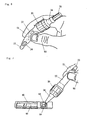
- FIG. 2 is a sectional view of a sample trituration vessel in Embodiment 2 of the present invention
- Fig. 3 is a front view of a trituration rod in the same.
- a trituration rod 40 of this Embodiment is equipped with a cylindrical and tapered rod body 41, and a head portion 43 provided at a lower end of the rod body 41.
- a first rugged portion 44 is formed at a lower end of the head portion 43.
- the first rugged portion 44 is composed of a plurality of protrusions.
- a slanted surface of the head portion 43 has a shape of a cone becoming narrow downward (that is, tapering off).
- a plenty of grooves are cut on the surface to form a second rugged portion 45.
- a plurality of vertical grooves are cut on an upper part of the rod body 41 to form a gripping part 42. Thereby, a hand of an operator gripping the trituration rod 40 is hard to slip.
- the sample trituration vessel of this Embodiment is equipped with a sample trituration vessel 20, a cap 30, and a nozzle 34.
- the sample trituration vessel 20 includes a tubular body 22 having an opening 21 at an upper end and a bottom part 23 at a lower end, respectively. Near the bottom part 23 of the tubular body 22, a tapered portion 24 that has a shape of a cone becoming narrow downward (that is, tapering off) is formed.
- the head portion 43 of the trituration rod 40 can be inserted from the opening 21 to the second rugged portion 26.
- the second rugged portion 45 is brought into contact with the second rugged portion 26.
- a first rugged portion 25 is formed on an upper surface of the bottom portion 23 upward (that is, meeting the first rugged portion 44 of the trituration rod 40).
- the first rugged portion 25 is composed of a plurality of protrusions like the first rugged portion 44.
- a flange 27 projecting in a radial direction is circumferentially provided at an upper part of the tubular body 22.
- a rib 28 connects the flange 27 and a lateral surface of the tubular body 22. The flange 27 and the rib 28, however, may be omitted.
- a male screw member 29 is formed on a part on the lateral surface of the tubular body 22 higher than the flange 27.
- a female screw member 31 corresponding to the male screw member 29 is formed on the cap 30. Accordingly, the male screw member 29 is screwed into the female screw member 31 when the cap 30 is downward rotated from the top of the tubular body 22. Then, the opening 21 is closed with the cap 30, and an inner space of the tubular body 22 is sealed.
- the sample trituration vessel 20 Prior to using the sample trituration vessel 20, for example, the sample trituration vessel 20 should be contained with a packing bag. In this case, it is preferable for the cap 30 to keep the sealing condition.
- the cap 30 is put off, and buffer 37 is poured into the tubular body 22. Then, the buffer 37 within the tubular body 22 keeps this state of being held thereby.
- the buffer 37 may have been poured prior to the use.
- the cap 30 may be put off In this Embodiment, however, the following is available.
- a notch 32 is provided protruding from a center of an upper end of the cap 30.
- a slit groove 33 is cut at a lower end of the notch 32, thereby making the neighborhood of the slit groove 33 weak adventurously.
- the notch 32 can be easily cut off when the notch 32 is folded bordering on the slit groove 33.
- an upper part of the opening 21 is connected with the exterior. This enables to insert the sample and the trituration rod into the tubular body 22 via a hole opened by removing the notch 32 without putting the cap 30 off.
- the nozzle 34 is put on the cap 30 when trituration of the sample has been completed.
- An applying port 35 having a shape of a tapering funnel is formed at an upper part of the nozzle 34.
- a filter 36 for removing impurity contained in the buffer 37 is equipped with a middle part of the nozzle 34. Accordingly, when an operator puts the nozzle 34 on, turns the applying port 35 down, and squeezes the tubular body 22 with his/her hand, the buffer 37 reaches the filter 36 via the opening 21 and the hole opened by removing the notch 34. The filter 36 removes impurity, and then the buffer 37 is expelled to outside from the applying port 35.
- the second rugged portion 26 may be constituted of a rough surface having the shape of stairs. This is preferable because not only the sample can be triturated with high efficiency contacting the sample with the rough surface but also this can make it easy to release the sample trituration vessel 20 from a die when the sample trituration vessel 20 is an injection molding product made from synthetic resin.
- the tubular body 22 may not be tapered as described in Embodiment 1. At least a part of the internal surface of the tubular body 22 may be formed as shown in Fig. 5 . These arrangements are preferable because not only the sample can be triturated with high efficiency when the sample is relatively hard but also these arrangements can make it easy to release the sample trituration vessel 20 from a die when the sample trituration vessel 20 is an injection molding product made from synthetic resin.
- the tubular body 22 is formed of transparent or translucent resin (flexible material). Accordingly, as shown in Fig. 6 , when an operator adds an external force to the tubular body 22 using his/her thumb 50, forefinger 51, or the like, the tubular body 22 is deformed so as to be able to break down the sample held within the tubular body 22.
- the tubular body 22 is transparent or translucence. The operator can see the state of buffer 37 from outside of the tubular body 22. The operator, therefore, can preferably perform trituration while adjusting pressure thereto.
- the nozzle cap 38 is removed as illustrated in Fig. 7 , and the buffer 37 filtered with the filter 36 is applied to a movable detector, which is preferable based on the immunochromatography method in view of easy and rapid operation thereof.
- the detector shown in Fig. 7 comprises: a holder 60; and a test piece 61 held by the holder 60.
- a sample-applying part of the test piece 61 exposes to the exterior via a sample-applying port 62 made in a jig equipped with the holder 60. It is, therefore, enough for the operator to merely apply the buffer 37 filtered with the filter 36 via the sample-applying port 62.
- Anti-SDV monoclonal antibodies were prepared according to the method of Kohler-Milstein (Nature, 256, 495-497, 1975 ). Antibody-producing cells were extracted from a spleen of a mouse immunized by SDV, and then were fused with mouse myeloma cells separately prepared, thereby obtaining hybridoma cells producing anti-SDV monoclonal antibodies 4E6 and hybridoma cells producing anti-SDV monoclonal antibodies 2G2. The hybridoma cells were cultured respectively, and were injected in the abdominal cavity of a mouse, thereby obtaining ascites thereof. Ammonium sulfate fraction and protein G column purification are performed on the obtained ascites, thereby obtaining anti-SDV monoclonal antibodies 4E6 and anti-SDV monoclonal antibodies 2G2.
- Colloidal gold was produced according to the method of G Frens (Nature, 241, 20-22, 1973 ). 40 milliliter of the anti-SDV monoclonal antibodies 2G2 are mixed to 10 microgram of colloidal gold at room temperature, thereby preparing colloidal gold (label component)-combined anti-SDV monoclonal antibodies.
- nitrocellulose membrane (Millipore Corp.: SCHF (trademark)) in the shape of lines, thereby forming a detection zone.
- the membrane was blocking-processed using casein solution, thereby preparing anti-SDV monoclonal antibody-turned in solid phase membrane.
- a piece of filter paper (applying portion), the colloidal gold-conjugated with anti-SDV monoclonal antibody-applied pad, the anti-SDV monoclonal antibody-turned in solid phase membrane, and another piece of filter paper were pasted on synthetic resin with adhesive in a manner such that each end of which overlaps 3 mm, thereby producing a test piece 61.
- the test piece 61 was fixed on a holder 60, thereby producing a detector.
- inflected trees 1 and 2 are orange trees inflected with fruit tree viruses SDV
- uninflected trees 1 and 2 are orange trees uninflected with fruit tree viruses SDV
- the result of sensitivity test with respect to these orange trees is as follows: Tree Name, Trituration Dilution ratio of trituration liquid *1 *2 *4 *8 *16 *32 *64 Inflected tree 1
- the pharynx is wiped with a cotton swab to extract fluid.
- the cotton swab is dipped into a vessel holding buffer therein.
- the cotton swab is squeezed from outside of the vessel to extract fluid that has penetrated with the cotton swab to the buffer, and then detection is performed using the buffer.
- the sample trituration vessel according to the present invention can be used as such a vessel. In this way, it is expected that efficiency of extracting a substance to be detected from the cotton swab is improved owing to the operation of the rugged portion.
- the inventors performed model experiment (1) and experiment using samples (2) with respect to influenza detection to obtain results thereof.
- the results are reported as follows.
- the procedures of the experiment are as follows.
- the same buds equipped with cotton swabs at ends are prepared, and then model mucus or suction liquid from a nasal cavity, which may include a substance to be detected, are put on tips of the cotton swabs.
- the same composition and amount of buffer solution is applied to a first vessel (hereinafter, "Comparative example 5") that is a vessel the rugged portion 9 of which has been removed from the vessel 5 of Fig. 1 , or a second vessel (hereinafter, “Example of the present invention”) of the vessel 20 of Fig. 2 .
- Extraction process of Comparative example 5 is as follows.
- the cotton swab on which the model mucus or the suction liquid from the nasal cavity is put is inserted into the bottom of the first vessel, and then fingers press the first vessel from outside and rub the cotton swab five times.
- Extraction process of Example of the present invention is as follows.
- the cotton swab on which the model mucus or the suction liquid from the nasal cavity is put is inserted into the bottom of the second vessel, and then fingers pinch the second vessel from outside and rotate the cotton bud from side to side five times.
- extraction rates belong to a range between 59.6 % and 92.6%, and 78.6% of average value is obtained.
- extraction rates belong to a range between 4.4% and 15.6%, and 8.2% of average value is obtained. That is, very higher extraction rates can be obtained according to Example of the present invention than Comparative example 5. Needless to say, the higher extraction rate is obtained, the more detection precision improves.
- Comparative example 5 since the cotton swab is rubbed by fingers, strong power of fingers is needed.
- the present invention has advantage that strong power is not needed and extraction process is easy. More concretely, according to Comparative example 5, the bottom of the vessel is shaped into a cylinder whose radius is greater than that of the cotton swab, and side portion of the vessel is hard to be deformed being disturbed by the bottom face of the vessel. It is also difficult to press the cotton swab. It is thought that the sample is not solved out enough even when the operator tries to rub and soften the cotton swab. On the other hand, according to Example of the present invention, since the bottom of the vessel is tapered and the rugged portion 26 is also formed, it is thought that merely rotating the bud easily causes a sufficient amount of the sample to solve out, thereby remarkably improving the extraction ratio.
- samples 1 to 3 are samples of influenza A type positive, and sample 4 is a sample of influenza B type positive.
- Extraction buffer or the like was the same as the model experiment. The sample was prepared by diluting extracted buffer in a series of the power of two, and then measurement was performed using influenza detection kits (product made by Mizuho medy Co., LTD., trademark: Quick Chaser Flu, No. 67500).
- Sample 1 has very high viscosity among Samples 1 to 4, and Sample 3 has high viscosity next thereto. Higher viscosity of the sample is, the higher effect the vessel according to the present invention earns.
Landscapes
- Physics & Mathematics (AREA)
- Health & Medical Sciences (AREA)
- Life Sciences & Earth Sciences (AREA)
- Chemical & Material Sciences (AREA)
- Analytical Chemistry (AREA)
- Biochemistry (AREA)
- General Health & Medical Sciences (AREA)
- General Physics & Mathematics (AREA)
- Immunology (AREA)
- Pathology (AREA)
- Engineering & Computer Science (AREA)
- Food Science & Technology (AREA)
- Sampling And Sample Adjustment (AREA)
- Investigating Or Analysing Biological Materials (AREA)
Applications Claiming Priority (2)
| Application Number | Priority Date | Filing Date | Title |
|---|---|---|---|
| JP2006012526 | 2006-01-20 | ||
| PCT/JP2007/050481 WO2007083617A1 (fr) | 2006-01-20 | 2007-01-16 | Recipient de trituration d'echantillons, outil et procede en faisant usage |
Publications (3)
| Publication Number | Publication Date |
|---|---|
| EP1975593A1 true EP1975593A1 (fr) | 2008-10-01 |
| EP1975593A4 EP1975593A4 (fr) | 2014-12-17 |
| EP1975593B1 EP1975593B1 (fr) | 2019-10-16 |
Family
ID=38287570
Family Applications (1)
| Application Number | Title | Priority Date | Filing Date |
|---|---|---|---|
| EP07706808.8A Ceased EP1975593B1 (fr) | 2006-01-20 | 2007-01-16 | Recipient de trituration d'echantillons et outil |
Country Status (3)
| Country | Link |
|---|---|
| US (1) | US8402846B2 (fr) |
| EP (1) | EP1975593B1 (fr) |
| WO (1) | WO2007083617A1 (fr) |
Cited By (1)
| Publication number | Priority date | Publication date | Assignee | Title |
|---|---|---|---|---|
| EP4059592A1 (fr) * | 2021-03-16 | 2022-09-21 | Swissmeca SA | Éprouvette, ainsi que dispositif et procédé de dispersion et d'homogénéisation |
Families Citing this family (14)
| Publication number | Priority date | Publication date | Assignee | Title |
|---|---|---|---|---|
| DE102008034085B4 (de) * | 2008-07-21 | 2016-03-31 | Kabe-Labortechnik Gmbh | Vorrichtung zur veterinärmedizinischen Probennahme |
| JP5080395B2 (ja) * | 2008-08-01 | 2012-11-21 | 積水メディカル株式会社 | 検体容器 |
| US8709359B2 (en) | 2011-01-05 | 2014-04-29 | Covaris, Inc. | Sample holder and method for treating sample material |
| EP3149151B1 (fr) * | 2014-05-30 | 2021-08-04 | Pressure Biosciences, Inc. | Dispositifs et procédés de préparation d'échantillon |
| JPWO2016031899A1 (ja) * | 2014-08-28 | 2017-06-15 | アルフレッサファーマ株式会社 | 検体試験容器用ノズルキャップ、ならびにそれを用いた検体試験容器および検体試験キット |
| ES2978108T3 (es) * | 2014-09-04 | 2024-09-05 | Becton Dickinson Co | Dispositivos y métodos para disociar una muestra de tejido biológico |
| US10422728B2 (en) | 2014-09-26 | 2019-09-24 | Denka Seiken Co. | Sample extraction kit and sample extraction method |
| EP3288459B1 (fr) * | 2015-04-29 | 2023-09-20 | Revvity Health Sciences, Inc. | Appareil de prélèvement et de distribution de spécimens |
| US10996146B2 (en) | 2017-06-01 | 2021-05-04 | Becton, Dickinson And Company | Devices for dissociating a biological tissue sample and methods of use thereof |
| CN112304720B (zh) * | 2019-07-26 | 2025-04-25 | 长江大学 | 一种植物营养成分测量装置 |
| CN111198117A (zh) * | 2020-01-22 | 2020-05-26 | 西南大学 | 一种简易双木棒交叉磨土制样方法 |
| CN114323829B (zh) * | 2021-11-10 | 2024-04-26 | 武汉市华大百果蔬农贸有限责任公司 | 一种带折叠功能的便携式前处理设备 |
| CN114950612B (zh) * | 2022-03-28 | 2024-08-06 | 上海国创医药股份有限公司 | 一种健脾止遗用的原材料研磨装置 |
| US11860070B1 (en) * | 2023-05-19 | 2024-01-02 | James L. Peterson | Volatile organic chemical in solid sample collection, processing, and measurement apparatus and method |
Family Cites Families (16)
| Publication number | Priority date | Publication date | Assignee | Title |
|---|---|---|---|---|
| US3786820A (en) * | 1973-02-20 | 1974-01-22 | R Kopfer | Mixer and applicator for fingernail repair material |
| JPS63112974A (ja) | 1986-10-31 | 1988-05-18 | Sakuma Seisakusho:Kk | 試料加工装置 |
| JPH075143B2 (ja) | 1989-05-26 | 1995-01-25 | 株式会社ミネロン | 電子部品収納容器 |
| US5114858A (en) * | 1990-06-26 | 1992-05-19 | E. I. Du Pont De Nemours And Company | Cellular component extraction process in a disposable filtration vessel |
| JP3000661B2 (ja) | 1990-11-15 | 2000-01-17 | 株式会社村田製作所 | 傾斜機能型誘電体セラミックス |
| JPH07113596B2 (ja) * | 1992-01-16 | 1995-12-06 | 島久薬品株式会社 | 破砕分散用袋 |
| IT1260682B (it) * | 1993-09-28 | 1996-04-22 | Consult T S S N C Di Roggero G | Dispositivo trituratore meccanico di materiale biologico |
| US5533683A (en) * | 1993-12-09 | 1996-07-09 | Biomedical Polymers, Inc. | Tissue grinding system |
| US5478311A (en) * | 1993-12-15 | 1995-12-26 | Klearman; Jeffrey D. | Hand held combination pill crushing and dispensing device |
| JP3468617B2 (ja) | 1995-06-26 | 2003-11-17 | ネクスタ株式会社 | 破砕袋 |
| JPH1090131A (ja) | 1996-09-12 | 1998-04-10 | Eiken Kizai Kk | 環境清浄度検査用拭き取り器具 |
| JP4043275B2 (ja) * | 2002-04-19 | 2008-02-06 | シスメックス株式会社 | 試料破砕具とそれを用いた試料調製装置 |
| JP4029280B2 (ja) * | 2002-09-06 | 2008-01-09 | 東洋紡績株式会社 | 試料粉砕具 |
| WO2005056748A1 (fr) * | 2003-12-08 | 2005-06-23 | Covaris, Inc. | Appareil et procedes de preparation d'echantillon |
| JP3853794B2 (ja) * | 2004-03-02 | 2006-12-06 | 株式会社ニッピ | 試料破砕器具及び試料破砕方法 |
| US7735763B2 (en) * | 2007-09-17 | 2010-06-15 | First Wave Products Group, Llc | Pill crusher with pill holder verification and safety features |
-
2007
- 2007-01-16 EP EP07706808.8A patent/EP1975593B1/fr not_active Ceased
- 2007-01-16 US US12/087,679 patent/US8402846B2/en not_active Expired - Fee Related
- 2007-01-16 WO PCT/JP2007/050481 patent/WO2007083617A1/fr not_active Ceased
Cited By (1)
| Publication number | Priority date | Publication date | Assignee | Title |
|---|---|---|---|---|
| EP4059592A1 (fr) * | 2021-03-16 | 2022-09-21 | Swissmeca SA | Éprouvette, ainsi que dispositif et procédé de dispersion et d'homogénéisation |
Also Published As
| Publication number | Publication date |
|---|---|
| US8402846B2 (en) | 2013-03-26 |
| US20090084202A1 (en) | 2009-04-02 |
| WO2007083617A1 (fr) | 2007-07-26 |
| EP1975593A4 (fr) | 2014-12-17 |
| EP1975593B1 (fr) | 2019-10-16 |
Similar Documents
| Publication | Publication Date | Title |
|---|---|---|
| EP1975593A1 (fr) | Recipient de trituration d'echantillons, outil et procede en faisant usage | |
| JP5203611B2 (ja) | 試料摩砕容器並びにそれを用いる用具及び方法 | |
| DE60032907T2 (de) | Wegwerf-testbehälter mit probenabgabevorrichtung | |
| CN1495420B (zh) | 自动重新密封的容器盖 | |
| DE69524324T2 (de) | Pipettierspitze | |
| EP2398591B1 (fr) | Dispositif et procédé de préparation de composants sanguins | |
| EP0734767A2 (fr) | Récepient pour le traitement à contamination réduite de liquides | |
| JP5542184B2 (ja) | 管内の生体サンプルのための液体処理プランジャ | |
| US20110015543A1 (en) | Fluid sample collection system | |
| US11448571B2 (en) | Specimen collection tip, specimen preparation container and specimen preparation kit | |
| CN104677689B (zh) | 吸取器、使用该吸取器的采样稀释装置、分析系统及采样分析方法 | |
| CN205741020U (zh) | 一种适用于pcr多联管的开盖装置 | |
| EP2754493B1 (fr) | Chambre destinée à contenir un échantillon avec une lame intégrée | |
| DE102013000901B4 (de) | Vorrichtung zur Aufnahme und Abgabe von Speichel | |
| DE19626234A1 (de) | Vorrichtung zur kontaminationsfreien Zu- und Abfuhr von Flüssigkeiten | |
| CN205007293U (zh) | 一种痰液样本处理装置 | |
| CN109307758A (zh) | 一种白细胞检测试剂盒 | |
| CN106290934A (zh) | 标本的处理、运输及检测方法 | |
| DE10128460A1 (de) | Vorrichtung und Verfahren zum Sammeln von kleinen wässrigen Flüssigkeitsproben | |
| CN216322026U (zh) | 输血科交叉配血试验用一次性取样滴管套 | |
| DE102016009414A1 (de) | Vorrichtung zur Überführung von Probematerial in eine Flüssigkeit | |
| CN201716224U (zh) | 拭子标本处理管 | |
| CN101013069A (zh) | 一种少量游离细胞或微小样品收集器 | |
| CN108192813A (zh) | 一种微量核酸洗脱收集装置 | |
| CN107828639A (zh) | 具有预处理功能的加样器及样本预处理、加样方法 |
Legal Events
| Date | Code | Title | Description |
|---|---|---|---|
| PUAI | Public reference made under article 153(3) epc to a published international application that has entered the european phase |
Free format text: ORIGINAL CODE: 0009012 |
|
| 17P | Request for examination filed |
Effective date: 20080807 |
|
| AK | Designated contracting states |
Kind code of ref document: A1 Designated state(s): DE FR GB |
|
| RIN1 | Information on inventor provided before grant (corrected) |
Inventor name: NARAHARA, KENJI Inventor name: MIMORI, TOMOHIRO |
|
| DAX | Request for extension of the european patent (deleted) | ||
| RBV | Designated contracting states (corrected) |
Designated state(s): DE FR GB |
|
| A4 | Supplementary search report drawn up and despatched |
Effective date: 20141119 |
|
| RIC1 | Information provided on ipc code assigned before grant |
Ipc: G01N 1/28 20060101AFI20141113BHEP |
|
| 17Q | First examination report despatched |
Effective date: 20171215 |
|
| GRAP | Despatch of communication of intention to grant a patent |
Free format text: ORIGINAL CODE: EPIDOSNIGR1 |
|
| RIC1 | Information provided on ipc code assigned before grant |
Ipc: G01N 1/28 20060101AFI20190607BHEP Ipc: B02C 19/08 20060101ALN20190607BHEP |
|
| GRAJ | Information related to disapproval of communication of intention to grant by the applicant or resumption of examination proceedings by the epo deleted |
Free format text: ORIGINAL CODE: EPIDOSDIGR1 |
|
| GRAJ | Information related to disapproval of communication of intention to grant by the applicant or resumption of examination proceedings by the epo deleted |
Free format text: ORIGINAL CODE: EPIDOSDIGR1 |
|
| RIC1 | Information provided on ipc code assigned before grant |
Ipc: G01N 1/28 20060101AFI20190620BHEP Ipc: B02C 19/08 20060101ALN20190620BHEP |
|
| INTG | Intention to grant announced |
Effective date: 20190703 |
|
| INTG | Intention to grant announced |
Effective date: 20190703 |
|
| INTC | Intention to grant announced (deleted) | ||
| GRAJ | Information related to disapproval of communication of intention to grant by the applicant or resumption of examination proceedings by the epo deleted |
Free format text: ORIGINAL CODE: EPIDOSDIGR1 |
|
| GRAL | Information related to payment of fee for publishing/printing deleted |
Free format text: ORIGINAL CODE: EPIDOSDIGR3 |
|
| GRAR | Information related to intention to grant a patent recorded |
Free format text: ORIGINAL CODE: EPIDOSNIGR71 |
|
| GRAS | Grant fee paid |
Free format text: ORIGINAL CODE: EPIDOSNIGR3 |
|
| RIC1 | Information provided on ipc code assigned before grant |
Ipc: B02C 19/08 20060101ALN20190729BHEP Ipc: G01N 1/28 20060101AFI20190729BHEP |
|
| GRAA | (expected) grant |
Free format text: ORIGINAL CODE: 0009210 |
|
| INTG | Intention to grant announced |
Effective date: 20190904 |
|
| AK | Designated contracting states |
Kind code of ref document: B1 Designated state(s): DE FR GB |
|
| REG | Reference to a national code |
Ref country code: GB Ref legal event code: FG4D |
|
| REG | Reference to a national code |
Ref country code: DE Ref legal event code: R096 Ref document number: 602007059364 Country of ref document: DE |
|
| REG | Reference to a national code |
Ref country code: DE Ref legal event code: R097 Ref document number: 602007059364 Country of ref document: DE |
|
| PLBE | No opposition filed within time limit |
Free format text: ORIGINAL CODE: 0009261 |
|
| STAA | Information on the status of an ep patent application or granted ep patent |
Free format text: STATUS: NO OPPOSITION FILED WITHIN TIME LIMIT |
|
| 26N | No opposition filed |
Effective date: 20200717 |
|
| PGFP | Annual fee paid to national office [announced via postgrant information from national office to epo] |
Ref country code: DE Payment date: 20240119 Year of fee payment: 18 Ref country code: GB Payment date: 20240124 Year of fee payment: 18 |
|
| PGFP | Annual fee paid to national office [announced via postgrant information from national office to epo] |
Ref country code: FR Payment date: 20240118 Year of fee payment: 18 |
|
| REG | Reference to a national code |
Ref country code: DE Ref legal event code: R119 Ref document number: 602007059364 Country of ref document: DE |
|
| GBPC | Gb: european patent ceased through non-payment of renewal fee |
Effective date: 20250116 |
|
| PG25 | Lapsed in a contracting state [announced via postgrant information from national office to epo] |
Ref country code: DE Free format text: LAPSE BECAUSE OF NON-PAYMENT OF DUE FEES Effective date: 20250801 |
|
| PG25 | Lapsed in a contracting state [announced via postgrant information from national office to epo] |
Ref country code: GB Free format text: LAPSE BECAUSE OF NON-PAYMENT OF DUE FEES Effective date: 20250116 |
|
| PG25 | Lapsed in a contracting state [announced via postgrant information from national office to epo] |
Ref country code: FR Free format text: LAPSE BECAUSE OF NON-PAYMENT OF DUE FEES Effective date: 20250131 |