EP1984935B1 - Low-pressure mercury vapor discharge lamp with amalgam - Google Patents
Low-pressure mercury vapor discharge lamp with amalgam Download PDFInfo
- Publication number
- EP1984935B1 EP1984935B1 EP07705734A EP07705734A EP1984935B1 EP 1984935 B1 EP1984935 B1 EP 1984935B1 EP 07705734 A EP07705734 A EP 07705734A EP 07705734 A EP07705734 A EP 07705734A EP 1984935 B1 EP1984935 B1 EP 1984935B1
- Authority
- EP
- European Patent Office
- Prior art keywords
- lamp
- amalgam
- discharge
- electrode
- lamp system
- Prior art date
- Legal status (The legal status is an assumption and is not a legal conclusion. Google has not performed a legal analysis and makes no representation as to the accuracy of the status listed.)
- Revoked
Links
- 229910000497 Amalgam Inorganic materials 0.000 title claims abstract description 81
- QSHDDOUJBYECFT-UHFFFAOYSA-N mercury Chemical compound [Hg] QSHDDOUJBYECFT-UHFFFAOYSA-N 0.000 title claims abstract description 41
- 238000010438 heat treatment Methods 0.000 claims abstract description 72
- 239000004020 conductor Substances 0.000 claims description 23
- XLYOFNOQVPJJNP-UHFFFAOYSA-N water Substances O XLYOFNOQVPJJNP-UHFFFAOYSA-N 0.000 claims description 15
- 229910052753 mercury Inorganic materials 0.000 claims description 10
- 238000004659 sterilization and disinfection Methods 0.000 claims description 6
- 239000002351 wastewater Substances 0.000 claims description 4
- 239000003570 air Substances 0.000 claims description 2
- 230000001105 regulatory effect Effects 0.000 claims description 2
- 238000007789 sealing Methods 0.000 claims description 2
- 230000002070 germicidal effect Effects 0.000 description 33
- 230000005855 radiation Effects 0.000 description 14
- 230000007423 decrease Effects 0.000 description 12
- 239000007789 gas Substances 0.000 description 7
- XKRFYHLGVUSROY-UHFFFAOYSA-N Argon Chemical compound [Ar] XKRFYHLGVUSROY-UHFFFAOYSA-N 0.000 description 4
- 238000000576 coating method Methods 0.000 description 4
- 239000000203 mixture Substances 0.000 description 3
- 229910052786 argon Inorganic materials 0.000 description 2
- QVQLCTNNEUAWMS-UHFFFAOYSA-N barium oxide Chemical compound [Ba]=O QVQLCTNNEUAWMS-UHFFFAOYSA-N 0.000 description 2
- 238000010276 construction Methods 0.000 description 2
- 230000001276 controlling effect Effects 0.000 description 2
- 239000003651 drinking water Substances 0.000 description 2
- 235000020188 drinking water Nutrition 0.000 description 2
- 235000013305 food Nutrition 0.000 description 2
- 238000005286 illumination Methods 0.000 description 2
- 239000011261 inert gas Substances 0.000 description 2
- 239000000976 ink Substances 0.000 description 2
- 238000009434 installation Methods 0.000 description 2
- 238000012423 maintenance Methods 0.000 description 2
- 229910052751 metal Inorganic materials 0.000 description 2
- 239000002184 metal Substances 0.000 description 2
- IATRAKWUXMZMIY-UHFFFAOYSA-N strontium oxide Chemical compound [O-2].[Sr+2] IATRAKWUXMZMIY-UHFFFAOYSA-N 0.000 description 2
- 241000894006 Bacteria Species 0.000 description 1
- 238000004378 air conditioning Methods 0.000 description 1
- BRPQOXSCLDDYGP-UHFFFAOYSA-N calcium oxide Chemical compound [O-2].[Ca+2] BRPQOXSCLDDYGP-UHFFFAOYSA-N 0.000 description 1
- ODINCKMPIJJUCX-UHFFFAOYSA-N calcium oxide Inorganic materials [Ca]=O ODINCKMPIJJUCX-UHFFFAOYSA-N 0.000 description 1
- 239000000292 calcium oxide Substances 0.000 description 1
- 239000011248 coating agent Substances 0.000 description 1
- 230000001419 dependent effect Effects 0.000 description 1
- 239000003344 environmental pollutant Substances 0.000 description 1
- 238000002474 experimental method Methods 0.000 description 1
- 230000006870 function Effects 0.000 description 1
- 229910052738 indium Inorganic materials 0.000 description 1
- APFVFJFRJDLVQX-UHFFFAOYSA-N indium atom Chemical compound [In] APFVFJFRJDLVQX-UHFFFAOYSA-N 0.000 description 1
- 238000004519 manufacturing process Methods 0.000 description 1
- 239000000463 material Substances 0.000 description 1
- 239000000155 melt Substances 0.000 description 1
- 231100000719 pollutant Toxicity 0.000 description 1
- 239000000843 powder Substances 0.000 description 1
- 230000001681 protective effect Effects 0.000 description 1
- 239000000126 substance Substances 0.000 description 1
- WFKWXMTUELFFGS-UHFFFAOYSA-N tungsten Chemical compound [W] WFKWXMTUELFFGS-UHFFFAOYSA-N 0.000 description 1
- 229910052721 tungsten Inorganic materials 0.000 description 1
- 239000010937 tungsten Substances 0.000 description 1
- 238000009423 ventilation Methods 0.000 description 1
- 238000004065 wastewater treatment Methods 0.000 description 1
- 238000004804 winding Methods 0.000 description 1
Images


Classifications
-
- H—ELECTRICITY
- H01—ELECTRIC ELEMENTS
- H01J—ELECTRIC DISCHARGE TUBES OR DISCHARGE LAMPS
- H01J61/00—Gas-discharge or vapour-discharge lamps
- H01J61/02—Details
- H01J61/24—Means for obtaining or maintaining the desired pressure within the vessel
- H01J61/28—Means for producing, introducing, or replenishing gas or vapour during operation of the lamp
-
- H—ELECTRICITY
- H01—ELECTRIC ELEMENTS
- H01J—ELECTRIC DISCHARGE TUBES OR DISCHARGE LAMPS
- H01J61/00—Gas-discharge or vapour-discharge lamps
- H01J61/02—Details
- H01J61/52—Cooling arrangements; Heating arrangements; Means for circulating gas or vapour within the discharge space
- H01J61/523—Heating or cooling particular parts of the lamp
-
- H—ELECTRICITY
- H01—ELECTRIC ELEMENTS
- H01J—ELECTRIC DISCHARGE TUBES OR DISCHARGE LAMPS
- H01J61/00—Gas-discharge or vapour-discharge lamps
- H01J61/70—Lamps with low-pressure unconstricted discharge having a cold pressure < 400 Torr
- H01J61/72—Lamps with low-pressure unconstricted discharge having a cold pressure < 400 Torr having a main light-emitting filling of easily vaporisable metal vapour, e.g. mercury
Definitions
- the invention relates to a lamp system comprising a low-pressure mercury vapor discharge lamp, the lamp comprising at least one discharge vessel enclosing, in a gastight manner, a discharge space provided with a filling of mercury and a rare gas, the discharge vessel having a first end section and a second end section, a first electrode arranged at the first end section and a second electrode arranged at the second end section for maintaining a discharge along a discharge path between the first electrode and the second electrode, an amalgam for regulating the mercury vapor pressure in the discharge vessel and having an optimal temperature range, a heating element arranged at the first end section for heating the amalgam to a temperature within its optimal temperature range, and an electronic circuit arranged to generate an electrical discharge current for maintaining the discharge, and an electrical heating current for heating the heating element independently of the electrical discharge current.
- the invention further relates to a water treatment system or an air treatment system comprising said lamp system.
- the invention also relates to a low-pressure mercury vapor discharge lamp for said lamp system.
- the invention also further
- mercury constitutes the primary component for the generation of ultraviolet (UV) radiation.
- a luminescent layer comprising a luminescent material, for example a fluorescent powder, may be present on an inner wall of the discharge vessel to convert UV radiation to radiation of other wavelengths, for example, to UV-B and UV-A radiation for tanning purposes or to visible radiation for general illumination purposes.
- Such discharge lamps are therefore also referred to as fluorescent lamps.
- the ultraviolet light generated may be used for manufacturing germicidal lamps (UV - C).
- the discharge vessel of a low-pressure mercury vapor discharge lamp is usually circular and comprises both elongate and compact embodiments.
- the tubular discharge vessel of compact fluorescent lamps comprises a collection of relatively short straight parts having a relatively small diameter, which straight parts are connected together by means of bridge parts or via bent parts.
- the means for maintaining a discharge in the discharge space may be electrodes arranged in the discharge space.
- external electrodes can be applied.
- External electrodes can be provided as a conductive coating at the end parts of the discharge vessel.
- the conductive coatings function as a capacitive electrode, between which a discharge extends during lamp operation along the axial distance between the external electrodes.
- Low-pressure mercury vapor discharge germicidal lamps predominantly generate UV-C radiation, and these types of lamps are used for disinfection of water and air, disinfection of foods, curing of inks and coatings, and destroying of pollutants in water and air.
- the principal radiation that is generated in such lamps has a wavelength of 254 nm, which prevents the growth of, for example, moulds and bacteria.
- the mercury vapor pressure greatly affects the operation of a low-pressure mercury vapor discharge (germicidal) lamp.
- a predetermined range of the mercury vapor pressure inside the discharge vessel is required.
- the mercury vapor pressure can be controlled within this predetermined range for a relatively broad temperature range, allowing operating the lamp at a high efficiency and hence a relatively high radiation output within this temperature range.
- the designation "optimal temperature range" for an amalgam is used to refer to the temperature range where the mercury vapor pressure is such that the radiation output of the lamp is at least 90 % of the maximal radiation output, i.e. under operating conditions where the mercury vapor pressure is optimal.
- Lamp efficiency is defined as the UV-C output power divided by the lamp input power.
- the published international patent application WO2004/089429A2 discloses a low-pressure mercury vapor discharge germicidal lamp with an amalgam positioned in an end section of the lamp, allowing efficient operation of the lamp over a relatively wide temperature range.
- the published patent application US5,095,336 discloses a fluorescent lamp with three amalgam patches internal to the lamp. Two patches are located at opposite ends of the lamp, and a third patch is centrally located. Each patch has an associated thermistor and an external heating element. The path temperature which correlates with the optimum lamp operating temperature is continuously monitored and adjustments are made to the heating elements to maintain the patches at desired optimum temperature. As a result an optimum axial illumination output of the lamp is provided.
- the temperature may change in such a way that the temperature of the amalgam is outside its optimal temperature range.
- a (germicidal) lamp has to be dimmable, i.e. reduction in the input power of the lamp in order to reduce the UV radiation output under conditions where a maximal output is not required. In case the lamp is dimmed, the temperature of the lamp will decrease.
- germicidal lamps for waste water treatment, for disinfection of drinking water, or for air treatment
- a decrease in the temperature of the water or air causes the temperature of the lamp to decrease.
- the positioning of the (germicidal) lamp i.e. horizontal versus vertical positioning of the lamp, also influences the temperature of the amalgam. Under these conditions the efficiency of the lamp decreases when the temperature of the amalgam becomes below its optimal temperature range.
- a lamp system characterized in that the amalgam is arranged at the first end section outside the discharge path and in that the lamp further comprises a control circuit for generating at least one control signal to activate the electronic circuit to generate the electrical heating current in dependence on at least the dimming level of the lamp.
- the amalgam is placed in the end section of the lamp, behind the electrode, in a relatively cool region of the lamp.
- the amalgam is positioned at the first end section such that in case the lamp operates at maximal input power, the temperature of the amalgam will not exceed the maximum value of its optimal temperature range, so that an optimal mercury-vapor pressure is achieved.
- the heating element is positioned adjacent to the amalgam.
- a control circuit activates the electronic circuit of the lamp system to generate an electric current that causes the heating element to heat the amalgam, resulting in an increase of the temperature of the amalgam to within its optimal temperature range.
- Lamp systems according to the invention operate at a relatively high efficiency over a relatively broad range of operating conditions, such as dimming level, temperature of the surroundings and positioning of the lamp, allowing to minimize the number of (germicidal) lamps required for a specific application, and thus reducing installation costs as well as maintenance costs.
- Another preferred embodiment of the lamp system according to the invention is characterized in that the first electrode and the second electrode are arranged in the discharge space.
- the heating element is arranged to heat the amalgam independently of the first electrode.
- the heating element is a filament circuit.
- Another preferred embodiment of the lamp system according to the invention is characterized in that the first electrode is further arranged to operate as the heating element.
- the first electrode for heating the amalgam, a relatively simple construction for controlling the amalgam temperature is provided.
- Another preferred embodiment of the lamp system according to the invention is characterized in that the first end section comprises a pressed end for sealing the first end section in a gastight manner, and that the amalgam is positioned in a recess of the pressed end on the side facing the discharge vessel.
- Another preferred embodiment of the lamp system according to the invention is characterized by a container, encapsulating the amalgam, adjacent to the heating element and having a gas opening enabling the exchange of mercury with the discharge space.
- Another preferred embodiment of the lamp system according to the invention is characterized by current supply conductors that issue through the first end section to outside the discharge vessel, the first electrode being coupled to the current supply conductors and the amalgam being supported by at least one current supply conductor.
- the amalgam is positioned at a fixed distance from the heating element, at a position where the temperature differences in case of dimming the lamp or in case of a change in temperature of the surroundings of the lamp, for example, are relatively small compared to other positions within the discharge space. Furthermore, in case the lamp is positioned in a vertical position, the amalgam is kept in its position during use of the lamp, even under operating conditions that cause the amalgam to melt.
- control circuit is further programmable to generate the at least one control signal in dependence on the measured voltage level of the lamp.
- the measured lamp voltage level is an indication of the efficiency of the lamp.
- a drop in the measured lamp voltage level is hence an indication that the temperature of the amalgam will decrease and heating of the amalgam may be required.
- control circuit is further programmable to generate the at least one control signal in dependence on the temperature level of the surroundings of the lamp.
- the temperature of the amalgam can be kept within its optimal temperature range.
- Another preferred embodiment of the lamp system according to the invention is characterized by a temperature sensor for measuring the temperature level at a position near the amalgam, and by the control circuit being programmable to generate the at least one control signal in dependence on the temperature level provided by the temperature sensor.
- a water treatment system or an air treatment system comprises at least one lamp system according to the invention.
- Lamp systems according to the invention operate at a relatively high efficiency over a relatively wide temperature range of the lamp and a wide range of operating conditions, allowing to minimize the number of germicidal lamps required for a specific water treatment system or air treatment system and thus reducing installation costs as well as maintenance costs.
- GB1062141 discloses an amalgam that can be moved with respect to the electrode.
- WO03/060950 discloses a heating element outside the lamp, the use of an electrode as the heating element is not disclosed.
- US5274305 discloses an amalgam with a separate heating element, in series with the electrode.
- FIG 1 is a schematic drawing of an embodiment of a lamp system according to the invention.
- the lamp system comprises a low-pressure mercury vapor discharge lamp 2 according to Figures 2 - 6 .
- the system further comprises a lamp ballast 38 for energizing the lamp 2.
- the lamp ballast 38 comprises a controller 40 and a heating circuit 42.
- the controller 40 and/or the heating circuit 42 may be a separate device.
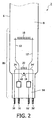
- FIGS 2 and 3 are schematic drawings of a first and a second embodiment, respectively, of a low-pressure mercury vapor discharge (germicidal) lamp for the lamp system as shown in Figure 1 .
- the lamp 2 has a gas discharge vessel 6 that encloses, in a gastight manner, a discharge space 8 containing a filling of mercury and an inert gas, for example argon. For clarity reasons, only a part of the lamp 2 is shown.
- the lamp 2 has two electrodes, of which only electrode 10, 30 is shown. Electrode 10, 30 is positioned in a first end section 28 of the germicidal lamp 2, and a second electrode is positioned in a second end section of the lamp, for maintaining a discharge in the discharge space 8. Alternatively, the electrodes are external electrodes.
- the electrode 10, 30 is a winding of tungsten covered with an electron-emitting substance, for example a mixture of barium oxide, calcium oxide and strontium oxide.
- Current-supply conductors 12, 12' are coupled to the electrode 10, 30 and pass through the sealed end 14 of the lamp to the exterior.
- the current-supply conductors 12, 12' are connected to contact pins 16, 16'.
- the sealed end 14 has a recess 20, in which an amalgam 18 is positioned.
- the recess 20 has an opening facing the discharge space 8 for exchange of mercury between the amalgam 18 and the discharge space 8.
- the lamp 2 further comprises a filament circuit 22 that is positioned adjacent to the amalgam 18.
- current-supply conductors 24, 24' are coupled to the filament circuit 22 and pass through the sealed end 14 to the exterior.
- the current-supply conductors 24, 24' are connected to contact pins 26, 26'.
- the filament 22 is integrated into the current supply conductor 12'.
- the lamp ballast 38 is arranged to generate a discharge current for energizing the electrode 10, 30, via contact pins 16, 16' and current-supply conductors 12, 12'. Using this discharge current, a gas discharge is maintained between the electrode 10, 30 and the other electrode during normal operation of the lamp.
- the lamp ballast 38 is further arranged to generate a first heating current via the heating circuit 42, independently of the discharge current, for heating the filament circuit 22, via contact pins 26, 26' and current-supply conductors 24, 24'( Figure 2 ) or via contact pins 16, 16' and current-supply conductors 12, 12' ( Figure 3 ). It is noted that in the embodiment of Figure 3 , the same heating current is applied to the filament circuit 22 and the electrode 30, but this heating current can be generated independently of the discharge current.
- the controller 40 is arranged to generate a control signal to activate the ballast to generate the first heating current.
- the lamp ballast 38 may also generate a second heating current for heating the electrode 10, 30, for example during start-up of the lamp 2, via contact pins 16, 16' and current-supply conductors 12, 12'.
- the amalgam 18 has a specific optimal temperature range, depending on its composition. For example, for an amalgam comprising Indium, this range is from 110 to 140 °C.
- the amalgam is positioned at the first end section 28 such that in case the germicidal lamp 2 operates at maximal input power, the temperature of the amalgam will not exceed the maximum value of its optimal temperature range, so that an optimal mercury-vapor pressure is achieved.
- a shield is positioned between the filament circuit 22 and the electrode 10, to create a separate chamber in which the filament circuit 22 is positioned.
- the shield has openings for allowing exchange of mercury between the amalgam 18 and the discharge space 8.
- the filament circuit 22 is positioned around at least a part of the sealed end 14 and is energized via current-supply conductors 24, 24'.
- the filament circuit is positioned inside at least a part of the sealed end 14. During operation, the filament circuit 22 heats the amalgam 18 inside the recess 20 by heating the sealed end 14.
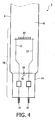
- FIGs 4 , 5 and 6 are schematic drawings of a third, fourth and fifth embodiment, respectively, of a low-pressure mercury vapor discharge (germicidal) lamp for a lamp system according to Figure 1 .
- the lamp 2 has a gas discharge vessel 6 that encloses a discharge space 8 containing a filling of mercury and an inert gas mixture, for example argon.
- the lamp 2 has two electrodes, of which only electrode 30 is shown. Electrode 30 is positioned in a first end section 28 of the lamp 2, and a second electrode is positioned in a second end section of the lamp, for maintaining a discharge in the discharge space 8.
- the electrodes are external electrodes.
- Current-supply conductors 12, 12' are coupled to the electrode 30 and pass through the sealed end 14 of the lamp to the exterior.
- the current-supply conductors 12, 12' are connected to contact pins 16, 16'.
- the lamp ballast 38 is arranged to generate a discharge current for energizing the electrode 30, via contact pins 16, 16' and current-supply conductors 12, 12'. Using this discharge current, a gas discharge is maintained between the two electrodes during normal operation of the lamp.
- the lamp ballast 38 is further arranged to generate a first heating current via the heating circuit 42, independently of the discharge current, for heating the electrode 30, via contact pins 16, 16' and current-supply conductors 12, 12'.
- the controller 40 is arranged to generate a control signal to activate the ballast to generate the first heating current.
- the lamp ballast 38 may also generate a second heating current for heating the electrode 30, for example during start-up of the lamp 2, via contact pins 16, 16' and current-supply conductors 12, 12'.
- the lamp 2 comprises an amalgam 18 that is positioned at the first end section 28 such that in case the germicidal lamp 2 operates at maximal input power, the temperature of the amalgam will not exceed the maximum value of its optimal temperature range, so that an optimal mercury-vapor pressure is achieved.
- the amalgam 18 is positioned in a recess 20 in the sealed end 14.
- the sealed end 14 has a relatively uniform temperature at varying operation conditions of the germicidal lamp 2.
- the amalgam 18 is positioned in a container 32 that is coupled to a metal strip 34.
- the other end of the metal strip 34 is connected to the sealed end 14.
- the container 32 has an opening for exchange of mercury between the amalgam 18 and the discharge space.
- the amalgam 18 is positioned in a container 32 that is coupled to the current-supply conductor 12 via a strip 36 of a non-electrically conducting material.
- the controller 40 is programmable to generate the control signal in dependence on the dimming level of the (germicidal) lamp 2.
- the temperature profile along the longitudinal axis of the lamp 2 changes.
- the temperature of the amalgam 18 decreases and goes outside its optimal temperature range at a certain critical dimming level of the lamp 2.
- the controller 40 can be programmed in such a way that, at this dimming level, the controller generates a control signal to trigger the ballast 38 to generate a first heating current to the filament circuit 22 of Figures 2 and 3 or to the electrode 30 of Figures 4 , 5 and 6 , respectively, for heating the amalgam 18.
- the level of the first heating current, as generated by the heating circuit 42, is chosen such that the temperature of the amalgam 18 will increase to a level within its optimal temperature range.
- the relationship between the level of the first heating current and the dimming level, in order to achieve a temperature of the amalgam within its optimal temperature range, has to be determined separately by means of standard experiments and can subsequently be programmed into the controller. This relationship depends on, amongst others, the distance between the filament circuit 22 of Figures 2 and 3 or the electrode 30 of Figures 4 , 5 and 6 and the amalgam 18, the diameter of the lamp, and the construction of the filament circuit 22 of Figures 2 and 3 or the electrode 30 of Figures 4 , 5 and 6 .
- the controller 40 In case the dimming level is subsequently increased to above the critical dimming level, the controller 40 generates a signal to trigger the ballast 38 to shut down the first heating current.
- the controller 40 is programmable to generate the control signal in dependence on the temperature level of the surroundings of the (germicidal) lamp, for example the water temperature. In case the temperature of the surroundings decreases, the temperature profile along the longitudinal axis of the lamp 2 changes. As a result, the temperature of the amalgam 18 decreases and goes outside its optimal temperature range at a certain temperature of the surroundings.
- the controller 40 can be programmed in such a way that at this temperature level of the surroundings of the lamp 2, the controller 40 generates a control signal to trigger the ballast to generate a first heating current to the filament circuit 22 of Figures 2 and 3 or to the electrode 30 of Figures 4 , 5 and 6 , respectively, for heating the amalgam 18.
- the level of the first heating current, as generated by the heating circuit 42, is chosen such that the temperature of the amalgam 18 will increase to a level within its optimal temperature range.
- the controller 40 is programmable to generate the control signal in dependence on both the dimming level of the (germicidal) lamp 2 and the temperature of the surroundings of the germicidal lamp 2.
- the relationship between the required level of the first heating current and the dimming level of the lamp 2 and/or the temperature of the surroundings of the lamp can be determined separately and programmed into the controller 40 in a way known to the person skilled in the art.
- the controller 40 is programmable to generate the control signal in dependence on the measured voltage level of the (germicidal) lamp 2. In case the measured voltage level of the lamp 2 drops, this is an indication of a reduction in the efficiency of the lamp. As a result, the temperature profile along the longitudinal axis of the lamp 2 changes. The temperature of the amalgam 18 decreases and goes outside its optimal temperature range at a certain critical measured voltage level of the lamp 2.
- the controller 40 can be programmed in such a way that at this measured lamp voltage level the controller generates a control signal to trigger the ballast 38 to generate a first heating current to the filament circuit 22 of Figures 2 and 3 or to the electrode 30 of Figures 4 , 5 and 6 , respectively, for heating the amalgam 18.
- the (germicidal) lamp 2 further comprises a temperature sensor for measuring the temperature level at a position in the discharge vessel near the amalgam, and the controller 40 is programmable to generate the control signal in dependence on the temperature level.
- the controller 40 In case the measured temperature level indicates that the temperature of the amalgam is below its optimal temperature range, due to dimming of the lamp for example, the controller 40 generates a control signal to trigger the ballast 38 to generate a first heating current to heat the amalgam to a temperature level inside its optimal temperature range. The moment the temperature level, as measured, indicates that the temperature of the amalgam is within its optimal temperature range, the controller 40 generates a control signal to trigger the ballast 38 to shut down the first heating current.
- Figure 7 shows the relative lamp efficiency, i.e. the actual lamp efficiency divided by the lamp efficiency achieved when the radiation output is maximal, versus the lamp input power in Watt for a low-pressure mercury vapor discharge lamp according to the prior art and a lamp system according to the invention.
- Line 44 shows the relative lamp efficiency versus the lamp input power for a low-pressure mercury-vapor discharge lamp according to the prior art.
- the relative efficiency increases to reach a maximum, and decreases at further increasing lamp input power.
- the temperature of the amalgam is within its optimal temperature range and hence a lamp efficiency of 90 % or higher is achieved.
- Line 46 shows the relative lamp efficiency versus the lamp input power for a lamp system according to the invention, comprising a lamp according to Figures 2 - 6 .
- the amalgam is maintained at a temperature within its optimal temperature range when the lamp input power decreases and hence the relative lamp efficiency is maintained at a value of 90 % or higher.
- FIG 8 is a schematic drawing of a water treatment system or an air treatment system according to the invention, comprising a plurality of germicidal lamps 2.
- the germicidal lamps 2 are placed vertically into a container 44. Alternatively, the germicidal lamps 2 can be placed in a horizontal position.
- the water or air 46 flows around the germicidal lamps 2, is irradiated by the germicidal lamps 2, and the generated UV radiation disinfects and/or purifies the water or air.
- the germicidal lamps 2 have contact pins on one side of the lamp. Alternatively, they have contact pins on both sides of the lamp.
- the germicidal lamps 2 each have their own lamp ballast, not shown in Figure 8 .
- a single ballast is shared by two or more germicidal lamps 2.
- the germicidal lamps 2 may be placed into a protective sleeve.
- the water treatment system may be used for treating waste water or for treating drinking water, for example.
- the air treatment system can be used in air conditioning systems or ventilation systems, for example.
- the germicidal lamps 2 can be used in a system for disinfection of food, or a system for curing inks or coatings.
Landscapes
- Discharge Lamp (AREA)
- Disinfection, Sterilisation Or Deodorisation Of Air (AREA)
- Physical Water Treatments (AREA)
- Circuit Arrangements For Discharge Lamps (AREA)
- Non-Portable Lighting Devices Or Systems Thereof (AREA)
- Apparatus For Disinfection Or Sterilisation (AREA)
Abstract
Description
- The invention relates to a lamp system comprising a low-pressure mercury vapor discharge lamp, the lamp comprising at least one discharge vessel enclosing, in a gastight manner, a discharge space provided with a filling of mercury and a rare gas, the discharge vessel having a first end section and a second end section, a first electrode arranged at the first end section and a second electrode arranged at the second end section for maintaining a discharge along a discharge path between the first electrode and the second electrode, an amalgam for regulating the mercury vapor pressure in the discharge vessel and having an optimal temperature range, a heating element arranged at the first end section for heating the amalgam to a temperature within its optimal temperature range, and an electronic circuit arranged to generate an electrical discharge current for maintaining the discharge, and an electrical heating current for heating the heating element independently of the electrical discharge current. The invention further relates to a water treatment system or an air treatment system comprising said lamp system. The invention also relates to a low-pressure mercury vapor discharge lamp for said lamp system. The invention also further relates to the use of said lamp system.
- In low-pressure mercury vapor discharge lamps, mercury constitutes the primary component for the generation of ultraviolet (UV) radiation. A luminescent layer comprising a luminescent material, for example a fluorescent powder, may be present on an inner wall of the discharge vessel to convert UV radiation to radiation of other wavelengths, for example, to UV-B and UV-A radiation for tanning purposes or to visible radiation for general illumination purposes. Such discharge lamps are therefore also referred to as fluorescent lamps. Alternatively, the ultraviolet light generated may be used for manufacturing germicidal lamps (UV - C). The discharge vessel of a low-pressure mercury vapor discharge lamp is usually circular and comprises both elongate and compact embodiments. Generally, the tubular discharge vessel of compact fluorescent lamps comprises a collection of relatively short straight parts having a relatively small diameter, which straight parts are connected together by means of bridge parts or via bent parts. The means for maintaining a discharge in the discharge space may be electrodes arranged in the discharge space. Alternatively, external electrodes can be applied. External electrodes can be provided as a conductive coating at the end parts of the discharge vessel. The conductive coatings function as a capacitive electrode, between which a discharge extends during lamp operation along the axial distance between the external electrodes.
- Low-pressure mercury vapor discharge germicidal lamps predominantly generate UV-C radiation, and these types of lamps are used for disinfection of water and air, disinfection of foods, curing of inks and coatings, and destroying of pollutants in water and air. The principal radiation that is generated in such lamps has a wavelength of 254 nm, which prevents the growth of, for example, moulds and bacteria.
- The mercury vapor pressure greatly affects the operation of a low-pressure mercury vapor discharge (germicidal) lamp. For an efficient operation of the lamp, a predetermined range of the mercury vapor pressure inside the discharge vessel is required. By using an amalgam, the mercury vapor pressure can be controlled within this predetermined range for a relatively broad temperature range, allowing operating the lamp at a high efficiency and hence a relatively high radiation output within this temperature range. In the description and claims of the current invention, the designation "optimal temperature range" for an amalgam is used to refer to the temperature range where the mercury vapor pressure is such that the radiation output of the lamp is at least 90 % of the maximal radiation output, i.e. under operating conditions where the mercury vapor pressure is optimal. Lamp efficiency is defined as the UV-C output power divided by the lamp input power. The published international patent application
WO2004/089429A2 discloses a low-pressure mercury vapor discharge germicidal lamp with an amalgam positioned in an end section of the lamp, allowing efficient operation of the lamp over a relatively wide temperature range. The published patent applicationUS5,095,336 discloses a fluorescent lamp with three amalgam patches internal to the lamp. Two patches are located at opposite ends of the lamp, and a third patch is centrally located. Each patch has an associated thermistor and an external heating element. The path temperature which correlates with the optimum lamp operating temperature is continuously monitored and adjustments are made to the heating elements to maintain the patches at desired optimum temperature. As a result an optimum axial illumination output of the lamp is provided. However, under certain conditions the temperature may change in such a way that the temperature of the amalgam is outside its optimal temperature range. For example, in certain applications a (germicidal) lamp has to be dimmable, i.e. reduction in the input power of the lamp in order to reduce the UV radiation output under conditions where a maximal output is not required. In case the lamp is dimmed, the temperature of the lamp will decrease. Furthermore, when using germicidal lamps for waste water treatment, for disinfection of drinking water, or for air treatment, a decrease in the temperature of the water or air causes the temperature of the lamp to decrease. The positioning of the (germicidal) lamp, i.e. horizontal versus vertical positioning of the lamp, also influences the temperature of the amalgam. Under these conditions the efficiency of the lamp decreases when the temperature of the amalgam becomes below its optimal temperature range. - It is an object of the invention to provide an efficient lamp system that at least partially solves the above-mentioned problem.
- This object is achieved with a lamp system according to the invention, characterized in that the amalgam is arranged at the first end section outside the discharge path and in that the lamp further comprises a control circuit for generating at least one control signal to activate the electronic circuit to generate the electrical heating current in dependence on at least the dimming level of the lamp. The amalgam is placed in the end section of the lamp, behind the electrode, in a relatively cool region of the lamp. The amalgam is positioned at the first end section such that in case the lamp operates at maximal input power, the temperature of the amalgam will not exceed the maximum value of its optimal temperature range, so that an optimal mercury-vapor pressure is achieved. The heating element is positioned adjacent to the amalgam. In case the temperature of the amalgam decreases to below its optimal temperature range as a result of dimming the lamp, a control circuit activates the electronic circuit of the lamp system to generate an electric current that causes the heating element to heat the amalgam, resulting in an increase of the temperature of the amalgam to within its optimal temperature range. Lamp systems according to the invention operate at a relatively high efficiency over a relatively broad range of operating conditions, such as dimming level, temperature of the surroundings and positioning of the lamp, allowing to minimize the number of (germicidal) lamps required for a specific application, and thus reducing installation costs as well as maintenance costs.
- It is noted that an electronic circuit for energizing a gas discharge lamp that generates an electrical discharge current independently of an electrical heating current is known per se. For example, British patent application
GB2316246A WO03/045117A1 Figure 3 , for operating a discharge lamp having a first switch mode power supply for supplying a discharge current to the lamp and a second switch mode power supply for heating the electrodes of the lamp. The second switch mode power supply is equipped with a power control loop comprising a memory for storing at least one electrode heating reference value. - Another preferred embodiment of the lamp system according to the invention is characterized in that the first electrode and the second electrode are arranged in the discharge space.
- Another preferred embodiment of the lamp system according to the invention is characterized in that the heating element is arranged to heat the amalgam independently of the first electrode. Another preferred embodiment of the lamp system according to the invention is characterized in that the heating element is a filament circuit. By using a separate filament circuit for heating the amalgam, the temperature of the amalgam can be controlled independently of that of the electrodes of the lamp.
- Another preferred embodiment of the lamp system according to the invention is characterized in that the first electrode is further arranged to operate as the heating element. By using the first electrode for heating the amalgam, a relatively simple construction for controlling the amalgam temperature is provided.
- Another preferred embodiment of the lamp system according to the invention is characterized in that the first end section comprises a pressed end for sealing the first end section in a gastight manner, and that the amalgam is positioned in a recess of the pressed end on the side facing the discharge vessel. Another preferred embodiment of the lamp system according to the invention is characterized by a container, encapsulating the amalgam, adjacent to the heating element and having a gas opening enabling the exchange of mercury with the discharge space. Another preferred embodiment of the lamp system according to the invention is characterized by current supply conductors that issue through the first end section to outside the discharge vessel, the first electrode being coupled to the current supply conductors and the amalgam being supported by at least one current supply conductor. In these embodiments, the amalgam is positioned at a fixed distance from the heating element, at a position where the temperature differences in case of dimming the lamp or in case of a change in temperature of the surroundings of the lamp, for example, are relatively small compared to other positions within the discharge space. Furthermore, in case the lamp is positioned in a vertical position, the amalgam is kept in its position during use of the lamp, even under operating conditions that cause the amalgam to melt.
- Another preferred embodiment of the lamp system according to the invention is characterized in that the control circuit is further programmable to generate the at least one control signal in dependence on the measured voltage level of the lamp. The measured lamp voltage level is an indication of the efficiency of the lamp. A drop in the measured lamp voltage level is hence an indication that the temperature of the amalgam will decrease and heating of the amalgam may be required.
- Another preferred embodiment of the lamp system according to the invention is characterized in that the control circuit is further programmable to generate the at least one control signal in dependence on the temperature level of the surroundings of the lamp. In case the temperature of the waste water or the air surrounding the lamp, for example, changes to a lower level, the temperature of the amalgam can be kept within its optimal temperature range.
- Another preferred embodiment of the lamp system according to the invention is characterized by a temperature sensor for measuring the temperature level at a position near the amalgam, and by the control circuit being programmable to generate the at least one control signal in dependence on the temperature level provided by the temperature sensor. By using the temperature value at a position near the amalgam for controlling the heating element, a direct and more accurate control of the temperature of the amalgam can be obtained under a broad range of conditions.
- According to the invention, a water treatment system or an air treatment system comprises at least one lamp system according to the invention. Lamp systems according to the invention operate at a relatively high efficiency over a relatively wide temperature range of the lamp and a wide range of operating conditions, allowing to minimize the number of germicidal lamps required for a specific water treatment system or air treatment system and thus reducing installation costs as well as maintenance costs. As the amalgam is positioned within a relatively cool region of the discharge space, it can be prevented that the amalgam melts during operation of the germicidal lamps and consequently moves out of position when the germicidal lamp is used in a vertical position.
- According to the invention, use of the lamp system according to claim 1 for disinfection of water, waste water or air is claimed by claim 13.
- It is noted that
GB1062141 WO03/060950 US5274305 , discloses an amalgam with a separate heating element, in series with the electrode. -
-
Figure 1 is a schematic drawing of an embodiment of a lamp system according to the invention. -
Figure 2 is a schematic drawing of a first embodiment of a low-pressure mercury vapor discharge lamp for a system according toFigure 1 . -
Figure 3 is a schematic drawing of a second embodiment of a low-pressure mercury vapor discharge lamp for a system according toFigure 1 . -
Figure 4 is a schematic drawing of a third embodiment of a low-pressure mercury vapor discharge lamp for a system according toFigure 1 . -
Figure 5 is a schematic drawing of a fourth embodiment of a low-pressure mercury vapor discharge lamp for a system according toFigure 1 . -
Figure 6 is a schematic drawing of a fifth embodiment of a low-pressure mercury vapor discharge lamp for a system according toFigure 1 . -
Figure 7 shows the relative lamp efficiency versus the lamp input power for a low-pressure mercury vapor discharge lamp according to the prior art and a lamp system according to the invention. -
Figure 8 is a schematic drawing of a water treatment system or air treatment system according to the invention. - The Figures are purely diagrammatic and not drawn to scale. Notably, some dimensions are shown strongly exaggerated for the sake of clarity. Similar components in the Figures are denoted by the same reference numerals as much as possible.
-
Figure 1 is a schematic drawing of an embodiment of a lamp system according to the invention. The lamp system comprises a low-pressure mercuryvapor discharge lamp 2 according toFigures 2 - 6 . The system further comprises alamp ballast 38 for energizing thelamp 2. Thelamp ballast 38 comprises acontroller 40 and aheating circuit 42. In an alternative embodiment, thecontroller 40 and/or theheating circuit 42 may be a separate device. -
Figures 2 and3 are schematic drawings of a first and a second embodiment, respectively, of a low-pressure mercury vapor discharge (germicidal) lamp for the lamp system as shown inFigure 1 . Thelamp 2 has agas discharge vessel 6 that encloses, in a gastight manner, adischarge space 8 containing a filling of mercury and an inert gas, for example argon. For clarity reasons, only a part of thelamp 2 is shown. Thelamp 2 has two electrodes, of which only electrode 10, 30 is shown.Electrode first end section 28 of thegermicidal lamp 2, and a second electrode is positioned in a second end section of the lamp, for maintaining a discharge in thedischarge space 8. Alternatively, the electrodes are external electrodes. Theelectrode supply conductors electrode end 14 of the lamp to the exterior. The current-supply conductors pins 16, 16'. The sealedend 14 has arecess 20, in which anamalgam 18 is positioned. Therecess 20 has an opening facing thedischarge space 8 for exchange of mercury between theamalgam 18 and thedischarge space 8. Thelamp 2 further comprises afilament circuit 22 that is positioned adjacent to theamalgam 18. Referring toFigure 2 , current-supply conductors 24, 24'are coupled to thefilament circuit 22 and pass through the sealedend 14 to the exterior. The current-supply conductors 24, 24' are connected to contactpins 26, 26'. Referring toFigure 3 , thefilament 22 is integrated into thecurrent supply conductor 12'. Referring again toFigures 2 and3 , thelamp ballast 38 is arranged to generate a discharge current for energizing theelectrode supply conductors electrode lamp ballast 38 is further arranged to generate a first heating current via theheating circuit 42, independently of the discharge current, for heating thefilament circuit 22, via contact pins 26, 26' and current-supply conductors 24, 24'(Figure 2 ) or via contact pins 16, 16' and current-supply conductors Figure 3 ). It is noted that in the embodiment ofFigure 3 , the same heating current is applied to thefilament circuit 22 and theelectrode 30, but this heating current can be generated independently of the discharge current. Thecontroller 40 is arranged to generate a control signal to activate the ballast to generate the first heating current. In addition, thelamp ballast 38 may also generate a second heating current for heating theelectrode lamp 2, via contact pins 16, 16' and current-supply conductors amalgam 18 has a specific optimal temperature range, depending on its composition. For example, for an amalgam comprising Indium, this range is from 110 to 140 °C. The amalgam is positioned at thefirst end section 28 such that in case thegermicidal lamp 2 operates at maximal input power, the temperature of the amalgam will not exceed the maximum value of its optimal temperature range, so that an optimal mercury-vapor pressure is achieved. Referring toFigure 2 , in an alternative embodiment, a shield, not shown inFigure 2 , is positioned between thefilament circuit 22 and theelectrode 10, to create a separate chamber in which thefilament circuit 22 is positioned. The shield has openings for allowing exchange of mercury between theamalgam 18 and thedischarge space 8. Referring again toFigure 2 , in an alternative embodiment thefilament circuit 22 is positioned around at least a part of the sealedend 14 and is energized via current-supply conductors 24, 24'. In a further alternative embodiment, the filament circuit is positioned inside at least a part of the sealedend 14. During operation, thefilament circuit 22 heats theamalgam 18 inside therecess 20 by heating the sealedend 14. -
Figures 4 ,5 and6 are schematic drawings of a third, fourth and fifth embodiment, respectively, of a low-pressure mercury vapor discharge (germicidal) lamp for a lamp system according toFigure 1 . Referring toFigures 4 ,5 and6 , for clarity reasons, only a part of thelamp 2 is shown. Thelamp 2 has agas discharge vessel 6 that encloses adischarge space 8 containing a filling of mercury and an inert gas mixture, for example argon. Thelamp 2 has two electrodes, of which only electrode 30 is shown.Electrode 30 is positioned in afirst end section 28 of thelamp 2, and a second electrode is positioned in a second end section of the lamp, for maintaining a discharge in thedischarge space 8. Alternatively, the electrodes are external electrodes. Current-supply conductors electrode 30 and pass through the sealedend 14 of the lamp to the exterior. The current-supply conductors 12, 12'are connected to contactpins 16, 16'. Thelamp ballast 38 is arranged to generate a discharge current for energizing theelectrode 30, via contact pins 16, 16' and current-supply conductors lamp ballast 38 is further arranged to generate a first heating current via theheating circuit 42, independently of the discharge current, for heating theelectrode 30, via contact pins 16, 16' and current-supply conductors controller 40 is arranged to generate a control signal to activate the ballast to generate the first heating current. In addition, thelamp ballast 38 may also generate a second heating current for heating theelectrode 30, for example during start-up of thelamp 2, via contact pins 16, 16' and current-supply conductors lamp 2 comprises anamalgam 18 that is positioned at thefirst end section 28 such that in case thegermicidal lamp 2 operates at maximal input power, the temperature of the amalgam will not exceed the maximum value of its optimal temperature range, so that an optimal mercury-vapor pressure is achieved. Referring toFigure 4 , theamalgam 18 is positioned in arecess 20 in the sealedend 14. The sealedend 14 has a relatively uniform temperature at varying operation conditions of thegermicidal lamp 2. Referring toFigure 5 , theamalgam 18 is positioned in acontainer 32 that is coupled to ametal strip 34. The other end of themetal strip 34 is connected to the sealedend 14. Thecontainer 32 has an opening for exchange of mercury between theamalgam 18 and the discharge space. Referring toFigure 6 , theamalgam 18 is positioned in acontainer 32 that is coupled to the current-supply conductor 12 via astrip 36 of a non-electrically conducting material. - In an embodiment of the lamp system according to the invention, the
controller 40 is programmable to generate the control signal in dependence on the dimming level of the (germicidal)lamp 2. In case thelamp 2 is dimmed in order to reduce the radiation output, the temperature profile along the longitudinal axis of thelamp 2 changes. As a result, the temperature of theamalgam 18 decreases and goes outside its optimal temperature range at a certain critical dimming level of thelamp 2. Thecontroller 40 can be programmed in such a way that, at this dimming level, the controller generates a control signal to trigger theballast 38 to generate a first heating current to thefilament circuit 22 ofFigures 2 and3 or to theelectrode 30 ofFigures 4 ,5 and6 , respectively, for heating theamalgam 18. The level of the first heating current, as generated by theheating circuit 42, is chosen such that the temperature of theamalgam 18 will increase to a level within its optimal temperature range. The relationship between the level of the first heating current and the dimming level, in order to achieve a temperature of the amalgam within its optimal temperature range, has to be determined separately by means of standard experiments and can subsequently be programmed into the controller. This relationship depends on, amongst others, the distance between thefilament circuit 22 ofFigures 2 and3 or theelectrode 30 ofFigures 4 ,5 and6 and theamalgam 18, the diameter of the lamp, and the construction of thefilament circuit 22 ofFigures 2 and3 or theelectrode 30 ofFigures 4 ,5 and6 . In case the dimming level is subsequently increased to above the critical dimming level, thecontroller 40 generates a signal to trigger theballast 38 to shut down the first heating current. In an alternative embodiment of the lamp system falling outside the scope of the invention, thecontroller 40 is programmable to generate the control signal in dependence on the temperature level of the surroundings of the (germicidal) lamp, for example the water temperature. In case the temperature of the surroundings decreases, the temperature profile along the longitudinal axis of thelamp 2 changes. As a result, the temperature of theamalgam 18 decreases and goes outside its optimal temperature range at a certain temperature of the surroundings. Thecontroller 40 can be programmed in such a way that at this temperature level of the surroundings of thelamp 2, thecontroller 40 generates a control signal to trigger the ballast to generate a first heating current to thefilament circuit 22 ofFigures 2 and3 or to theelectrode 30 ofFigures 4 ,5 and6 , respectively, for heating theamalgam 18. The level of the first heating current, as generated by theheating circuit 42, is chosen such that the temperature of theamalgam 18 will increase to a level within its optimal temperature range. In a further alternative embodiment falling within the scope of the invention, thecontroller 40 is programmable to generate the control signal in dependence on both the dimming level of the (germicidal)lamp 2 and the temperature of the surroundings of thegermicidal lamp 2. The relationship between the required level of the first heating current and the dimming level of thelamp 2 and/or the temperature of the surroundings of the lamp can be determined separately and programmed into thecontroller 40 in a way known to the person skilled in the art. In another further, non-inventive, alternative embodiment, thecontroller 40 is programmable to generate the control signal in dependence on the measured voltage level of the (germicidal)lamp 2. In case the measured voltage level of thelamp 2 drops, this is an indication of a reduction in the efficiency of the lamp. As a result, the temperature profile along the longitudinal axis of thelamp 2 changes. The temperature of theamalgam 18 decreases and goes outside its optimal temperature range at a certain critical measured voltage level of thelamp 2. Thecontroller 40 can be programmed in such a way that at this measured lamp voltage level the controller generates a control signal to trigger theballast 38 to generate a first heating current to thefilament circuit 22 ofFigures 2 and3 or to theelectrode 30 ofFigures 4 ,5 and6 , respectively, for heating theamalgam 18. In another further alternative embodiment of the lamp system falling outside the scope of the invention, the (germicidal)lamp 2 further comprises a temperature sensor for measuring the temperature level at a position in the discharge vessel near the amalgam, and thecontroller 40 is programmable to generate the control signal in dependence on the temperature level. In case the measured temperature level indicates that the temperature of the amalgam is below its optimal temperature range, due to dimming of the lamp for example, thecontroller 40 generates a control signal to trigger theballast 38 to generate a first heating current to heat the amalgam to a temperature level inside its optimal temperature range. The moment the temperature level, as measured, indicates that the temperature of the amalgam is within its optimal temperature range, thecontroller 40 generates a control signal to trigger theballast 38 to shut down the first heating current. -
Figure 7 shows the relative lamp efficiency, i.e. the actual lamp efficiency divided by the lamp efficiency achieved when the radiation output is maximal, versus the lamp input power in Watt for a low-pressure mercury vapor discharge lamp according to the prior art and a lamp system according to the invention.Line 44 shows the relative lamp efficiency versus the lamp input power for a low-pressure mercury-vapor discharge lamp according to the prior art. At increasing lamp input power, the relative efficiency increases to reach a maximum, and decreases at further increasing lamp input power. Within a relatively small range of the lamp input power, the temperature of the amalgam is within its optimal temperature range and hence a lamp efficiency of 90 % or higher is achieved.Line 46 shows the relative lamp efficiency versus the lamp input power for a lamp system according to the invention, comprising a lamp according toFigures 2 - 6 . The amalgam is maintained at a temperature within its optimal temperature range when the lamp input power decreases and hence the relative lamp efficiency is maintained at a value of 90 % or higher. -
Figure 8 is a schematic drawing of a water treatment system or an air treatment system according to the invention, comprising a plurality ofgermicidal lamps 2. Thegermicidal lamps 2 are placed vertically into acontainer 44. Alternatively, thegermicidal lamps 2 can be placed in a horizontal position. The water orair 46 flows around thegermicidal lamps 2, is irradiated by thegermicidal lamps 2, and the generated UV radiation disinfects and/or purifies the water or air. Thegermicidal lamps 2 have contact pins on one side of the lamp. Alternatively, they have contact pins on both sides of the lamp. Thegermicidal lamps 2 each have their own lamp ballast, not shown inFigure 8 . In an alternative embodiment, a single ballast is shared by two or moregermicidal lamps 2. Thegermicidal lamps 2 may be placed into a protective sleeve. The water treatment system may be used for treating waste water or for treating drinking water, for example. The air treatment system can be used in air conditioning systems or ventilation systems, for example. - In an alternative embodiment, the
germicidal lamps 2 can be used in a system for disinfection of food, or a system for curing inks or coatings. - It should be noted that the above-mentioned embodiments illustrate rather than limit the invention, and that those skilled in the art will be able to design many alternative embodiments without departing from the scope of the appended claims. In the claims, any reference signs placed between parentheses shall not be construed as limiting the claim. The word "comprising" does not exclude the presence of elements or steps other than those listed in a claim. The word "a" or "an" preceding an element does not exclude the presence of a plurality of such elements. In the device claim enumerating several means, several of these means can be embodied by one and the same item of hardware. The mere fact that certain measures are recited in mutually different dependent claims does not indicate that a combination of these measures cannot be used to advantage.
Claims (13)
- A lamp system comprising a low-pressure mercury vapor discharge lamp, the lamp comprising:- at least one discharge vessel (6) enclosing, in a gastight manner, a discharge space (8) provided with a filling of mercury and a rare gas, the discharge vessel having a first end section (28) and a second end section,- a first electrode (10, 30) arranged at the first end section and a second electrode arranged at the second end section for maintaining a discharge along a discharge path between the first electrode and the second electrode,- an amalgam (18) for regulating the mercury vapor pressure in the discharge vessel and having an optimal temperature range,- a heating element (22) arranged at the first end section for heating the amalgam to a temperature within its optimal temperature range,- an electronic circuit (38) arranged to generate an electrical discharge current for maintaining the discharge, and an electrical heating current for heating the heating element (22), independently of the electrical discharge current,characterized in that:- the amalgam (18) is arranged at the first end section outside the discharge path,and in that the lamp system further comprises:- a control circuit (40) for generating at least one control signal to activate the electronic circuit to generate the electrical heating current in dependence on at least the dimming level of the lamp.
- A lamp system according to claim 1, characterized in that the first electrode (10, 30) and the second electrode are arranged in the discharge space.
- A lamp system according to claim 1 or 2, characterized in that the heating element (22) is arranged to heat the amalgam (18) independently of the first electrode (10).
- A lamp system according to claim 3, characterized in that the heating element (22) is a filament circuit.
- A lamp system according to claim 1 or 2, characterized in that the first electrode is further arranged to operate as the heating element.
- A lamp system according to claim 3 or 5, characterized in that the first end section comprises a pressed end (14) for sealing the first end section in a gastight manner, and that the amalgam (18) is positioned in a recess (20) of the pressed end on the side facing the discharge vessel (6).
- A lamp system according to claim 3 or 5, characterized by a container (32), encapsulating the amalgam adjacent to the heating element and having a gas opening enabling the exchange of mercury with the discharge space.
- A lamp system according to claims 3 to 5, characterized by current supply conductors (12, 12') that issue through the first end section to outside the discharge vessel, the first electrode (10, 30) being coupled to the current supply conductors and the amalgam (18) being supported by at least one current supply conductor (12).
- A lamp system according to claim 6, 7 or 8, characterized in that the control circuit (40) is further programmable to generate the at least one control signal in dependence on the measured voltage level of the lamp.
- A lamp system according to claim 6, 7 or 8, characterized in that the control circuit (40) is further programmable to generate the at least one control signal in dependence on the temperature level of the surroundings of the lamp.
- A lamp system according to claim 6, 7 or 8, characterized by:- a temperature sensor for measuring the temperature level at a position near the amalgam,- the control circuit (40) being further programmable to generate the at least one control signal in dependence on the temperature level provided by the temperature sensor.
- A water treatment system or an air treatment system comprising at least one lamp system according to anyone of the claims 1 to 11.
- Use of a lamp system according to claim 1 for disinfection of water, waste water or air.
Priority Applications (2)
| Application Number | Priority Date | Filing Date | Title |
|---|---|---|---|
| EP07705734A EP1984935B1 (en) | 2006-02-10 | 2007-01-30 | Low-pressure mercury vapor discharge lamp with amalgam |
| EP12152823.6A EP2447981B2 (en) | 2006-02-10 | 2007-01-30 | Low-pressure mercury vapor discharge lamp with amalgam, lamp system, water treatment system, use of a lamp system |
Applications Claiming Priority (3)
| Application Number | Priority Date | Filing Date | Title |
|---|---|---|---|
| EP06101521 | 2006-02-10 | ||
| PCT/IB2007/050304 WO2007091187A1 (en) | 2006-02-10 | 2007-01-30 | Low-pressure mercury vapor discharge lamp with amalgam |
| EP07705734A EP1984935B1 (en) | 2006-02-10 | 2007-01-30 | Low-pressure mercury vapor discharge lamp with amalgam |
Related Child Applications (2)
| Application Number | Title | Priority Date | Filing Date |
|---|---|---|---|
| EP12152823.6A Division EP2447981B2 (en) | 2006-02-10 | 2007-01-30 | Low-pressure mercury vapor discharge lamp with amalgam, lamp system, water treatment system, use of a lamp system |
| EP12152823.6 Division-Into | 2012-01-27 |
Publications (2)
| Publication Number | Publication Date |
|---|---|
| EP1984935A1 EP1984935A1 (en) | 2008-10-29 |
| EP1984935B1 true EP1984935B1 (en) | 2012-06-27 |
Family
ID=37684944
Family Applications (2)
| Application Number | Title | Priority Date | Filing Date |
|---|---|---|---|
| EP07705734A Revoked EP1984935B1 (en) | 2006-02-10 | 2007-01-30 | Low-pressure mercury vapor discharge lamp with amalgam |
| EP12152823.6A Active EP2447981B2 (en) | 2006-02-10 | 2007-01-30 | Low-pressure mercury vapor discharge lamp with amalgam, lamp system, water treatment system, use of a lamp system |
Family Applications After (1)
| Application Number | Title | Priority Date | Filing Date |
|---|---|---|---|
| EP12152823.6A Active EP2447981B2 (en) | 2006-02-10 | 2007-01-30 | Low-pressure mercury vapor discharge lamp with amalgam, lamp system, water treatment system, use of a lamp system |
Country Status (5)
| Country | Link |
|---|---|
| US (1) | US8018130B2 (en) |
| EP (2) | EP1984935B1 (en) |
| JP (2) | JP4981819B2 (en) |
| CN (2) | CN101379586B (en) |
| WO (1) | WO2007091187A1 (en) |
Cited By (2)
| Publication number | Priority date | Publication date | Assignee | Title |
|---|---|---|---|---|
| EP2779210A1 (en) | 2013-03-14 | 2014-09-17 | Heraeus Noblelight GmbH | Mercury vapour discharge lamp and method for its production |
| WO2020148597A1 (en) | 2019-01-18 | 2020-07-23 | Trojan Technologies Group Ulc | Lamp sensor modulation of a power supply |
Families Citing this family (23)
| Publication number | Priority date | Publication date | Assignee | Title |
|---|---|---|---|---|
| JP2009262098A (en) * | 2008-04-28 | 2009-11-12 | Ne Chemcat Corp | Exhaust gas clarifying method using selective reduction catalyst |
| DE102009014942B3 (en) * | 2009-03-30 | 2010-08-26 | Heraeus Noblelight Gmbh | Dimmable amalgam lamp and method of operating the amalgam lamp in dimming |
| FR2957909B1 (en) * | 2010-03-29 | 2012-07-20 | Rc Lux | LIQUID DISPENSER AND METHOD OF OPERATING A DISPENSER OF A LIQUID |
| DE102010014040B4 (en) | 2010-04-06 | 2012-04-12 | Heraeus Noblelight Gmbh | Method for operating an amalgam lamp |
| US8648530B2 (en) * | 2011-06-30 | 2014-02-11 | General Electric Company | Amalgam temperature maintaining device for dimmable fluorescent lamps |
| RU2497227C2 (en) * | 2012-01-27 | 2013-10-27 | Виктор Александрович Долгих | Generation method of emission on resonant junctions of atoms of metals |
| AU2013266576A1 (en) * | 2012-05-21 | 2015-01-22 | Hayward Industries, Inc. | Dynamic ultraviolet lamp ballast system |
| CN104202867A (en) * | 2014-08-04 | 2014-12-10 | 深圳市聚智德科技有限公司 | Automatic sterilization lamp |
| DE102015107694A1 (en) | 2015-05-18 | 2016-11-24 | Zed Ziegler Electronic Devices Gmbh | Gas discharge lamp and device for its temperature |
| JP6692522B2 (en) * | 2015-12-10 | 2020-05-13 | 岩崎電気株式会社 | Low-pressure mercury lamp and device using the same |
| EP3211656B1 (en) * | 2016-02-23 | 2018-09-19 | Xylem IP Management S.à.r.l. | Low-pressure ultraviolet radiator with multiple filaments |
| EP3267466B1 (en) * | 2016-07-08 | 2019-09-11 | Xylem Europe GmbH | Uv mercury low-pressure lamp with amalgam deposit |
| KR102414268B1 (en) | 2016-07-22 | 2022-06-29 | 엘지전자 주식회사 | Air conditioner |
| KR102393890B1 (en) | 2016-07-22 | 2022-05-03 | 엘지전자 주식회사 | Air conditioner |
| KR102477412B1 (en) | 2016-07-22 | 2022-12-15 | 엘지전자 주식회사 | Ultraviolet sterilization module, and air conditioner having the same |
| KR20180010877A (en) | 2016-07-22 | 2018-01-31 | 엘지전자 주식회사 | Ultraviolet rays sterilization module and air conditioner comprising the same |
| HUE062894T2 (en) | 2018-01-24 | 2023-12-28 | Xylem Europe Gmbh | Germicidal amalgam lamp with temperature sensor for optimized operation |
| DE102020203417A1 (en) * | 2020-03-17 | 2021-09-23 | Heraeus Noblelight Gmbh | Low pressure mercury vapor discharge lamp and lamp system |
| US11769658B2 (en) * | 2020-07-28 | 2023-09-26 | Trojan Technologies Group Ulc | Lamp with temperature control |
| CN113380601A (en) * | 2021-07-14 | 2021-09-10 | 佛山市耀清紫外科技有限公司 | External solid mercury alloy ultraviolet lamp and production process thereof |
| US12187626B2 (en) | 2021-09-20 | 2025-01-07 | Sudhish Madapur SWAIN | Apparatus and method for purifying water |
| US12582733B2 (en) | 2023-03-12 | 2026-03-24 | Tru-D Smartuvc, Llc | Parallel heating system and method for amalgam lamps |
| CN118403710B (en) * | 2024-05-15 | 2025-01-07 | 兴化市润禾食品有限公司 | Breaker for food processing |
Family Cites Families (39)
| Publication number | Priority date | Publication date | Assignee | Title |
|---|---|---|---|---|
| US3336502A (en) | 1963-12-31 | 1967-08-15 | Sylvania Electric Prod | Automatic heater control system for amalgam pressure control of fluorescent lamps |
| US3619697A (en) * | 1964-07-09 | 1971-11-09 | Westinghouse Electric Corp | Mercury vapor discharge lamp and pressure-regulating means therefor |
| US3851207A (en) | 1972-08-01 | 1974-11-26 | Gen Electric | Stabilized high intensity sodium vapor lamp |
| US3859555A (en) * | 1974-04-08 | 1975-01-07 | Gte Sylvania Inc | Fluorescent lamp containing-amalgam-forming material |
| US4117299A (en) * | 1977-02-17 | 1978-09-26 | Westinghouse Electric Corp. | Method of tipping refractory metal tubulation |
| JPS5586063A (en) * | 1978-12-22 | 1980-06-28 | Mitsubishi Electric Corp | Discharge lamp |
| US4437041A (en) | 1981-11-12 | 1984-03-13 | General Electric Company | Amalgam heating system for solenoidal electric field lamps |
| JPS60127633A (en) * | 1983-12-12 | 1985-07-08 | Toshiba Corp | Production of metal vapor discharge lamp |
| JPS6171540A (en) * | 1984-09-17 | 1986-04-12 | Toshiba Corp | Fluorescent lamp device |
| JPS6362144A (en) | 1986-09-02 | 1988-03-18 | Matsushita Electronics Corp | Electric bulb type fluorescent lamp |
| JPH01253198A (en) | 1988-03-31 | 1989-10-09 | Toshiba Lighting & Technol Corp | Discharge lamp lighting device |
| US4827313A (en) | 1988-07-11 | 1989-05-02 | Xerox Corporation | Mechanism and method for controlling the temperature and output of an amalgam fluorescent lamp |
| JPH03208251A (en) * | 1990-01-11 | 1991-09-11 | Toshiba Lighting & Technol Corp | Chipless discharge tube |
| US5095336A (en) * | 1990-11-08 | 1992-03-10 | Xerox Corporation | Temperature control of a fluorescent lamp having a central and two end amalgam patches |
| US5274305A (en) * | 1991-12-04 | 1993-12-28 | Gte Products Corporation | Low pressure mercury discharge lamp with thermostatic control of mercury vapor pressure |
| US5294867A (en) * | 1992-03-13 | 1994-03-15 | Gte Products Corporation | Low pressure mercury vapor discharge lamp containing an amalgam |
| ES2109425T3 (en) * | 1992-10-21 | 1998-01-16 | Koninkl Philips Electronics Nv | LIGHTING SET AND LOW PRESSURE DISCHARGE LAMP WITHOUT ELECTRODE SUITABLE FOR USE IN SUCH SET. |
| GB2316246A (en) | 1996-08-05 | 1998-02-18 | Bf Goodrich Avionics Systemc I | Intensity control for fluorescent lamps |
| JPH1074488A (en) * | 1996-08-30 | 1998-03-17 | Matsushita Electron Corp | Mercury discharge lamp device |
| JPH10312772A (en) * | 1997-05-14 | 1998-11-24 | Matsushita Electron Corp | Low pressure mercury discharge lamp and manufacture thereof |
| JPH1110157A (en) * | 1997-06-26 | 1999-01-19 | Toshiba Lighting & Technol Corp | Sterilizer and hot water circulation bath system |
| JP3275797B2 (en) * | 1997-09-10 | 2002-04-22 | 松下電器産業株式会社 | Low pressure mercury vapor discharge lamp |
| JPH11273622A (en) * | 1998-03-24 | 1999-10-08 | Toshiba Lighting & Technology Corp | Low pressure mercury vapor discharge lamp unit and fluid sterilizer |
| JP2000173537A (en) * | 1998-09-29 | 2000-06-23 | Toshiba Lighting & Technology Corp | Low pressure mercury vapor discharge lamp and lighting equipment |
| AU5032700A (en) * | 1999-05-21 | 2000-12-12 | Life Spring Limited Partnership | User-activated ultra-violet water treatment unit |
| JP4025462B2 (en) * | 1999-06-11 | 2007-12-19 | 株式会社日本フォトサイエンス | Low pressure mercury vapor discharge lamp and ultraviolet irradiation apparatus using the same |
| EP1452073A1 (en) | 2001-11-23 | 2004-09-01 | Koninklijke Philips Electronics N.V. | Device for heating electrodes of a discharge lamp |
| DE10201617C5 (en) * | 2002-01-16 | 2010-07-08 | Wedeco Ag Water Technology | Amalgam-doped low-pressure mercury UV emitter |
| JP2003234084A (en) | 2002-02-07 | 2003-08-22 | Hitachi Ltd | Fluorescent lamp and lighting device using the same |
| JP2003346712A (en) | 2002-05-29 | 2003-12-05 | Hitachi Lighting Ltd | Fluorescent lamp, and lighting device using the same |
| CN1288941C (en) | 2002-10-08 | 2006-12-06 | 马士科技有限公司 | A device for rapidly reaching maximum brightness for fluorescent lamps |
| JP4082238B2 (en) * | 2003-02-24 | 2008-04-30 | 松下電器産業株式会社 | High pressure discharge lamp lighting device |
| US7095167B2 (en) * | 2003-04-03 | 2006-08-22 | Light Sources, Inc. | Germicidal low pressure mercury vapor discharge lamp with amalgam location permitting high output |
| US20070145880A1 (en) * | 2003-06-26 | 2007-06-28 | Koninklijke Philips Electronics N.V. | Low pressure mercury vapor discharge lamp |
| EP1652213A2 (en) * | 2003-07-29 | 2006-05-03 | Koninklijke Philips Electronics N.V. | Low-pressure mercury vapor discharge lamp having determined probability of failure |
| US20080252218A1 (en) * | 2004-02-05 | 2008-10-16 | Koninklijke Philips Electronic, N.V. | Low-Pressure Mercury Vapor Discharge Lamp |
| JP2005327565A (en) * | 2004-05-13 | 2005-11-24 | Feelux Co Ltd | Dimming control device for illuminating lamp using temperature compensation |
| JP2006231150A (en) * | 2005-02-23 | 2006-09-07 | Ebara Corp | Photocatalyst, method for manufacturing the same and method and apparatus for treating water by using the same |
| CN1710702A (en) | 2005-06-20 | 2005-12-21 | 马士科技有限公司 | Three-filament fluorescent lamp |
-
2007
- 2007-01-30 CN CN2007800048935A patent/CN101379586B/en active Active
- 2007-01-30 EP EP07705734A patent/EP1984935B1/en not_active Revoked
- 2007-01-30 US US12/278,291 patent/US8018130B2/en active Active
- 2007-01-30 JP JP2008553861A patent/JP4981819B2/en active Active
- 2007-01-30 CN CN201210281644.3A patent/CN102832099B/en active Active
- 2007-01-30 WO PCT/IB2007/050304 patent/WO2007091187A1/en not_active Ceased
- 2007-01-30 EP EP12152823.6A patent/EP2447981B2/en active Active
-
2012
- 2012-02-16 JP JP2012031920A patent/JP5596720B2/en active Active
Cited By (3)
| Publication number | Priority date | Publication date | Assignee | Title |
|---|---|---|---|---|
| EP2779210A1 (en) | 2013-03-14 | 2014-09-17 | Heraeus Noblelight GmbH | Mercury vapour discharge lamp and method for its production |
| DE102013102600A1 (en) | 2013-03-14 | 2014-10-02 | Heraeus Noblelight Gmbh | Mercury vapor discharge lamp and method for its production |
| WO2020148597A1 (en) | 2019-01-18 | 2020-07-23 | Trojan Technologies Group Ulc | Lamp sensor modulation of a power supply |
Also Published As
| Publication number | Publication date |
|---|---|
| US8018130B2 (en) | 2011-09-13 |
| EP2447981A1 (en) | 2012-05-02 |
| EP2447981B2 (en) | 2020-08-05 |
| CN102832099B (en) | 2016-03-23 |
| JP4981819B2 (en) | 2012-07-25 |
| CN101379586B (en) | 2013-03-27 |
| US20090026965A1 (en) | 2009-01-29 |
| JP2009526357A (en) | 2009-07-16 |
| CN101379586A (en) | 2009-03-04 |
| EP2447981B1 (en) | 2013-07-10 |
| EP1984935A1 (en) | 2008-10-29 |
| CN102832099A (en) | 2012-12-19 |
| WO2007091187A1 (en) | 2007-08-16 |
| JP2012109264A (en) | 2012-06-07 |
| JP5596720B2 (en) | 2014-09-24 |
Similar Documents
| Publication | Publication Date | Title |
|---|---|---|
| EP1984935B1 (en) | Low-pressure mercury vapor discharge lamp with amalgam | |
| CN101253600B (en) | Ultraviolet spotlight and radiation source module and processing system containing the ultraviolet spotlight | |
| KR102824911B1 (en) | mercury discharge lamp | |
| JP5517107B2 (en) | Amalgam type low-pressure mercury lamp and its lamp lighting power supply | |
| US20070145880A1 (en) | Low pressure mercury vapor discharge lamp | |
| KR100687946B1 (en) | Flash discharge lamp and light energy irradiation device | |
| CA2753011C (en) | Dimmable amalgam lamp and method for operating the amalgam lamp while dimmed | |
| EP3267466B1 (en) | Uv mercury low-pressure lamp with amalgam deposit | |
| KR102127274B1 (en) | Low pressure UV emitter with multiple filaments | |
| US20060175975A1 (en) | Fluorescent lamp with auxiliary discharge and method for manufacturing the same | |
| EP2260504B1 (en) | Discharge tube for compact fluorescent lamp | |
| JP6692522B2 (en) | Low-pressure mercury lamp and device using the same | |
| CN1830058A (en) | Fluorescent lamp with auxiliary discharge and method for manufacturing the same |
Legal Events
| Date | Code | Title | Description |
|---|---|---|---|
| PUAI | Public reference made under article 153(3) epc to a published international application that has entered the european phase |
Free format text: ORIGINAL CODE: 0009012 |
|
| 17P | Request for examination filed |
Effective date: 20080910 |
|
| AK | Designated contracting states |
Kind code of ref document: A1 Designated state(s): AT BE BG CH CY CZ DE DK EE ES FI FR GB GR HU IE IS IT LI LT LU LV MC NL PL PT RO SE SI SK TR |
|
| 17Q | First examination report despatched |
Effective date: 20100621 |
|
| GRAP | Despatch of communication of intention to grant a patent |
Free format text: ORIGINAL CODE: EPIDOSNIGR1 |
|
| GRAS | Grant fee paid |
Free format text: ORIGINAL CODE: EPIDOSNIGR3 |
|
| GRAA | (expected) grant |
Free format text: ORIGINAL CODE: 0009210 |
|
| AK | Designated contracting states |
Kind code of ref document: B1 Designated state(s): AT BE BG CH CY CZ DE DK EE ES FI FR GB GR HU IE IS IT LI LT LU LV MC NL PL PT RO SE SI SK TR |
|
| DAX | Request for extension of the european patent (deleted) | ||
| REG | Reference to a national code |
Ref country code: GB Ref legal event code: FG4D |
|
| REG | Reference to a national code |
Ref country code: CH Ref legal event code: EP |
|
| REG | Reference to a national code |
Ref country code: AT Ref legal event code: REF Ref document number: 564592 Country of ref document: AT Kind code of ref document: T Effective date: 20120715 |
|
| REG | Reference to a national code |
Ref country code: IE Ref legal event code: FG4D |
|
| REG | Reference to a national code |
Ref country code: GB Ref legal event code: 746 Effective date: 20120724 |
|
| REG | Reference to a national code |
Ref country code: DE Ref legal event code: R096 Ref document number: 602007023586 Country of ref document: DE Effective date: 20120830 |
|
| REG | Reference to a national code |
Ref country code: DE Ref legal event code: R084 Ref document number: 602007023586 Country of ref document: DE Effective date: 20120714 |
|
| PG25 | Lapsed in a contracting state [announced via postgrant information from national office to epo] |
Ref country code: SE Free format text: LAPSE BECAUSE OF FAILURE TO SUBMIT A TRANSLATION OF THE DESCRIPTION OR TO PAY THE FEE WITHIN THE PRESCRIBED TIME-LIMIT Effective date: 20120627 Ref country code: FI Free format text: LAPSE BECAUSE OF FAILURE TO SUBMIT A TRANSLATION OF THE DESCRIPTION OR TO PAY THE FEE WITHIN THE PRESCRIBED TIME-LIMIT Effective date: 20120627 Ref country code: LT Free format text: LAPSE BECAUSE OF FAILURE TO SUBMIT A TRANSLATION OF THE DESCRIPTION OR TO PAY THE FEE WITHIN THE PRESCRIBED TIME-LIMIT Effective date: 20120627 |
|
| REG | Reference to a national code |
Ref country code: NL Ref legal event code: VDEP Effective date: 20120627 |
|
| REG | Reference to a national code |
Ref country code: AT Ref legal event code: MK05 Ref document number: 564592 Country of ref document: AT Kind code of ref document: T Effective date: 20120627 |
|
| REG | Reference to a national code |
Ref country code: LT Ref legal event code: MG4D Effective date: 20120627 |
|
| PG25 | Lapsed in a contracting state [announced via postgrant information from national office to epo] |
Ref country code: GR Free format text: LAPSE BECAUSE OF FAILURE TO SUBMIT A TRANSLATION OF THE DESCRIPTION OR TO PAY THE FEE WITHIN THE PRESCRIBED TIME-LIMIT Effective date: 20120928 Ref country code: LV Free format text: LAPSE BECAUSE OF FAILURE TO SUBMIT A TRANSLATION OF THE DESCRIPTION OR TO PAY THE FEE WITHIN THE PRESCRIBED TIME-LIMIT Effective date: 20120627 Ref country code: SI Free format text: LAPSE BECAUSE OF FAILURE TO SUBMIT A TRANSLATION OF THE DESCRIPTION OR TO PAY THE FEE WITHIN THE PRESCRIBED TIME-LIMIT Effective date: 20120627 |
|
| PG25 | Lapsed in a contracting state [announced via postgrant information from national office to epo] |
Ref country code: CY Free format text: LAPSE BECAUSE OF FAILURE TO SUBMIT A TRANSLATION OF THE DESCRIPTION OR TO PAY THE FEE WITHIN THE PRESCRIBED TIME-LIMIT Effective date: 20120627 Ref country code: CZ Free format text: LAPSE BECAUSE OF FAILURE TO SUBMIT A TRANSLATION OF THE DESCRIPTION OR TO PAY THE FEE WITHIN THE PRESCRIBED TIME-LIMIT Effective date: 20120627 Ref country code: EE Free format text: LAPSE BECAUSE OF FAILURE TO SUBMIT A TRANSLATION OF THE DESCRIPTION OR TO PAY THE FEE WITHIN THE PRESCRIBED TIME-LIMIT Effective date: 20120627 Ref country code: BE Free format text: LAPSE BECAUSE OF FAILURE TO SUBMIT A TRANSLATION OF THE DESCRIPTION OR TO PAY THE FEE WITHIN THE PRESCRIBED TIME-LIMIT Effective date: 20120627 Ref country code: AT Free format text: LAPSE BECAUSE OF FAILURE TO SUBMIT A TRANSLATION OF THE DESCRIPTION OR TO PAY THE FEE WITHIN THE PRESCRIBED TIME-LIMIT Effective date: 20120627 Ref country code: SK Free format text: LAPSE BECAUSE OF FAILURE TO SUBMIT A TRANSLATION OF THE DESCRIPTION OR TO PAY THE FEE WITHIN THE PRESCRIBED TIME-LIMIT Effective date: 20120627 Ref country code: IS Free format text: LAPSE BECAUSE OF FAILURE TO SUBMIT A TRANSLATION OF THE DESCRIPTION OR TO PAY THE FEE WITHIN THE PRESCRIBED TIME-LIMIT Effective date: 20121027 Ref country code: RO Free format text: LAPSE BECAUSE OF FAILURE TO SUBMIT A TRANSLATION OF THE DESCRIPTION OR TO PAY THE FEE WITHIN THE PRESCRIBED TIME-LIMIT Effective date: 20120627 |
|
| PG25 | Lapsed in a contracting state [announced via postgrant information from national office to epo] |
Ref country code: PT Free format text: LAPSE BECAUSE OF FAILURE TO SUBMIT A TRANSLATION OF THE DESCRIPTION OR TO PAY THE FEE WITHIN THE PRESCRIBED TIME-LIMIT Effective date: 20121029 Ref country code: IT Free format text: LAPSE BECAUSE OF FAILURE TO SUBMIT A TRANSLATION OF THE DESCRIPTION OR TO PAY THE FEE WITHIN THE PRESCRIBED TIME-LIMIT Effective date: 20120627 Ref country code: PL Free format text: LAPSE BECAUSE OF FAILURE TO SUBMIT A TRANSLATION OF THE DESCRIPTION OR TO PAY THE FEE WITHIN THE PRESCRIBED TIME-LIMIT Effective date: 20120627 |
|
| PG25 | Lapsed in a contracting state [announced via postgrant information from national office to epo] |
Ref country code: NL Free format text: LAPSE BECAUSE OF FAILURE TO SUBMIT A TRANSLATION OF THE DESCRIPTION OR TO PAY THE FEE WITHIN THE PRESCRIBED TIME-LIMIT Effective date: 20120627 |
|
| PLBI | Opposition filed |
Free format text: ORIGINAL CODE: 0009260 |
|
| PG25 | Lapsed in a contracting state [announced via postgrant information from national office to epo] |
Ref country code: ES Free format text: LAPSE BECAUSE OF FAILURE TO SUBMIT A TRANSLATION OF THE DESCRIPTION OR TO PAY THE FEE WITHIN THE PRESCRIBED TIME-LIMIT Effective date: 20121008 Ref country code: DK Free format text: LAPSE BECAUSE OF FAILURE TO SUBMIT A TRANSLATION OF THE DESCRIPTION OR TO PAY THE FEE WITHIN THE PRESCRIBED TIME-LIMIT Effective date: 20120627 |
|
| 26 | Opposition filed |
Opponent name: HERAEUS NOBLELIGHT GMBH Effective date: 20130322 |
|
| PLAX | Notice of opposition and request to file observation + time limit sent |
Free format text: ORIGINAL CODE: EPIDOSNOBS2 |
|
| REG | Reference to a national code |
Ref country code: DE Ref legal event code: R026 Ref document number: 602007023586 Country of ref document: DE Effective date: 20130322 |
|
| PG25 | Lapsed in a contracting state [announced via postgrant information from national office to epo] |
Ref country code: BG Free format text: LAPSE BECAUSE OF FAILURE TO SUBMIT A TRANSLATION OF THE DESCRIPTION OR TO PAY THE FEE WITHIN THE PRESCRIBED TIME-LIMIT Effective date: 20120927 |
|
| PG25 | Lapsed in a contracting state [announced via postgrant information from national office to epo] |
Ref country code: MC Free format text: LAPSE BECAUSE OF NON-PAYMENT OF DUE FEES Effective date: 20130131 |
|
| REG | Reference to a national code |
Ref country code: CH Ref legal event code: PL |
|
| PLAF | Information modified related to communication of a notice of opposition and request to file observations + time limit |
Free format text: ORIGINAL CODE: EPIDOSCOBS2 |
|
| RAP2 | Party data changed (patent owner data changed or rights of a patent transferred) |
Owner name: KONINKLIJKE PHILIPS N.V. |
|
| REG | Reference to a national code |
Ref country code: IE Ref legal event code: MM4A |
|
| PG25 | Lapsed in a contracting state [announced via postgrant information from national office to epo] |
Ref country code: LI Free format text: LAPSE BECAUSE OF NON-PAYMENT OF DUE FEES Effective date: 20130131 Ref country code: CH Free format text: LAPSE BECAUSE OF NON-PAYMENT OF DUE FEES Effective date: 20130131 |
|
| PLBB | Reply of patent proprietor to notice(s) of opposition received |
Free format text: ORIGINAL CODE: EPIDOSNOBS3 |
|
| PG25 | Lapsed in a contracting state [announced via postgrant information from national office to epo] |
Ref country code: IE Free format text: LAPSE BECAUSE OF NON-PAYMENT OF DUE FEES Effective date: 20130130 |
|
| REG | Reference to a national code |
Ref country code: DE Ref legal event code: R082 Ref document number: 602007023586 Country of ref document: DE Representative=s name: MEISSNER, BOLTE & PARTNER GBR, DE |
|
| REG | Reference to a national code |
Ref country code: DE Ref legal event code: R082 Ref document number: 602007023586 Country of ref document: DE Representative=s name: MEISSNER BOLTE PATENTANWAELTE RECHTSANWAELTE P, DE Effective date: 20140328 Ref country code: DE Ref legal event code: R081 Ref document number: 602007023586 Country of ref document: DE Owner name: PHILIPS LIGHTING HOLDING B.V., NL Free format text: FORMER OWNER: KONINKLIJKE PHILIPS ELECTRONICS N.V., EINDHOVEN, NL Effective date: 20140328 Ref country code: DE Ref legal event code: R081 Ref document number: 602007023586 Country of ref document: DE Owner name: KONINKLIJKE PHILIPS N.V., NL Free format text: FORMER OWNER: KONINKLIJKE PHILIPS ELECTRONICS N.V., EINDHOVEN, NL Effective date: 20140328 Ref country code: DE Ref legal event code: R082 Ref document number: 602007023586 Country of ref document: DE Representative=s name: MEISSNER, BOLTE & PARTNER GBR, DE Effective date: 20140328 |
|
| REG | Reference to a national code |
Ref country code: FR Ref legal event code: CA Effective date: 20141126 Ref country code: FR Ref legal event code: CD Owner name: KONINKLIJKE PHILIPS N.V., NL Effective date: 20141126 |
|
| RDAF | Communication despatched that patent is revoked |
Free format text: ORIGINAL CODE: EPIDOSNREV1 |
|
| APAH | Appeal reference modified |
Free format text: ORIGINAL CODE: EPIDOSCREFNO |
|
| APBM | Appeal reference recorded |
Free format text: ORIGINAL CODE: EPIDOSNREFNO |
|
| APBP | Date of receipt of notice of appeal recorded |
Free format text: ORIGINAL CODE: EPIDOSNNOA2O |
|
| PG25 | Lapsed in a contracting state [announced via postgrant information from national office to epo] |
Ref country code: TR Free format text: LAPSE BECAUSE OF FAILURE TO SUBMIT A TRANSLATION OF THE DESCRIPTION OR TO PAY THE FEE WITHIN THE PRESCRIBED TIME-LIMIT Effective date: 20120627 |
|
| APBQ | Date of receipt of statement of grounds of appeal recorded |
Free format text: ORIGINAL CODE: EPIDOSNNOA3O |
|
| PG25 | Lapsed in a contracting state [announced via postgrant information from national office to epo] |
Ref country code: LU Free format text: LAPSE BECAUSE OF NON-PAYMENT OF DUE FEES Effective date: 20130130 Ref country code: HU Free format text: LAPSE BECAUSE OF FAILURE TO SUBMIT A TRANSLATION OF THE DESCRIPTION OR TO PAY THE FEE WITHIN THE PRESCRIBED TIME-LIMIT; INVALID AB INITIO Effective date: 20070130 |
|
| REG | Reference to a national code |
Ref country code: FR Ref legal event code: PLFP Year of fee payment: 10 |
|
| REG | Reference to a national code |
Ref country code: GB Ref legal event code: 732E Free format text: REGISTERED BETWEEN 20161006 AND 20161012 |
|
| REG | Reference to a national code |
Ref country code: FR Ref legal event code: PLFP Year of fee payment: 11 |
|
| REG | Reference to a national code |
Ref country code: DE Ref legal event code: R082 Ref document number: 602007023586 Country of ref document: DE Representative=s name: MEISSNER BOLTE PATENTANWAELTE RECHTSANWAELTE P, DE Ref country code: DE Ref legal event code: R081 Ref document number: 602007023586 Country of ref document: DE Owner name: PHILIPS LIGHTING HOLDING B.V., NL Free format text: FORMER OWNER: KONINKLIJKE PHILIPS N.V., EINDHOVEN, NL |
|
| REG | Reference to a national code |
Ref country code: FR Ref legal event code: PLFP Year of fee payment: 12 |
|
| PGFP | Annual fee paid to national office [announced via postgrant information from national office to epo] |
Ref country code: FR Payment date: 20190128 Year of fee payment: 13 Ref country code: GB Payment date: 20190130 Year of fee payment: 13 |
|
| PGFP | Annual fee paid to national office [announced via postgrant information from national office to epo] |
Ref country code: DE Payment date: 20190401 Year of fee payment: 13 |
|
| REG | Reference to a national code |
Ref country code: DE Ref legal event code: R064 Ref document number: 602007023586 Country of ref document: DE Ref country code: DE Ref legal event code: R103 Ref document number: 602007023586 Country of ref document: DE |
|
| APBU | Appeal procedure closed |
Free format text: ORIGINAL CODE: EPIDOSNNOA9O |
|
| RAP2 | Party data changed (patent owner data changed or rights of a patent transferred) |
Owner name: KONINKLIJKE PHILIPS N.V. |
|
| RDAG | Patent revoked |
Free format text: ORIGINAL CODE: 0009271 |
|
| STAA | Information on the status of an ep patent application or granted ep patent |
Free format text: STATUS: PATENT REVOKED |
|
| REG | Reference to a national code |
Ref country code: FI Ref legal event code: MGE |
|
| 27W | Patent revoked |
Effective date: 20191125 |
|
| GBPR | Gb: patent revoked under art. 102 of the ep convention designating the uk as contracting state |
Effective date: 20191125 |