EP1988248A2 - Dichtungsgehäuse und Dichtung mit seitlichen Dichtungsprofilen - Google Patents
Dichtungsgehäuse und Dichtung mit seitlichen Dichtungsprofilen Download PDFInfo
- Publication number
- EP1988248A2 EP1988248A2 EP08007444A EP08007444A EP1988248A2 EP 1988248 A2 EP1988248 A2 EP 1988248A2 EP 08007444 A EP08007444 A EP 08007444A EP 08007444 A EP08007444 A EP 08007444A EP 1988248 A2 EP1988248 A2 EP 1988248A2
- Authority
- EP
- European Patent Office
- Prior art keywords
- seal
- housing
- groove
- door
- housing part
- Prior art date
- Legal status (The legal status is an assumption and is not a legal conclusion. Google has not performed a legal analysis and makes no representation as to the accuracy of the status listed.)
- Withdrawn
Links
- 238000007789 sealing Methods 0.000 claims abstract description 53
- XAGFODPZIPBFFR-UHFFFAOYSA-N aluminium Chemical compound [Al] XAGFODPZIPBFFR-UHFFFAOYSA-N 0.000 claims description 2
- 229910052782 aluminium Inorganic materials 0.000 claims description 2
- 229920001971 elastomer Polymers 0.000 claims description 2
- 239000000806 elastomer Substances 0.000 claims description 2
- 239000006260 foam Substances 0.000 claims description 2
- 238000000034 method Methods 0.000 claims description 2
- 238000004026 adhesive bonding Methods 0.000 claims 1
- 239000000779 smoke Substances 0.000 description 5
- 239000002023 wood Substances 0.000 description 5
- 239000007787 solid Substances 0.000 description 2
- 238000003780 insertion Methods 0.000 description 1
- 230000037431 insertion Effects 0.000 description 1
- 238000003801 milling Methods 0.000 description 1
- 230000035515 penetration Effects 0.000 description 1
- 230000001960 triggered effect Effects 0.000 description 1
Images


Classifications
-
- E—FIXED CONSTRUCTIONS
- E06—DOORS, WINDOWS, SHUTTERS, OR ROLLER BLINDS IN GENERAL; LADDERS
- E06B—FIXED OR MOVABLE CLOSURES FOR OPENINGS IN BUILDINGS, VEHICLES, FENCES OR LIKE ENCLOSURES IN GENERAL, e.g. DOORS, WINDOWS, BLINDS, GATES
- E06B7/00—Special arrangements or measures in connection with doors or windows
- E06B7/16—Sealing arrangements on wings or parts co-operating with the wings
- E06B7/18—Sealing arrangements on wings or parts co-operating with the wings by means of movable edgings, e.g. draught sealings additionally used for bolting, e.g. by spring force or with operating lever
- E06B7/20—Sealing arrangements on wings or parts co-operating with the wings by means of movable edgings, e.g. draught sealings additionally used for bolting, e.g. by spring force or with operating lever automatically withdrawn when the wing is opened, e.g. by means of magnetic attraction, a pin or an inclined surface, especially for sills
- E06B7/215—Sealing arrangements on wings or parts co-operating with the wings by means of movable edgings, e.g. draught sealings additionally used for bolting, e.g. by spring force or with operating lever automatically withdrawn when the wing is opened, e.g. by means of magnetic attraction, a pin or an inclined surface, especially for sills with sealing strip being moved to a retracted position by elastic means, e.g. springs
Definitions
- the invention relates to a seal housing for a self-releasing when closing a door or a window seal for mounting in a groove of a door leaf or window sash, with a housing part having a longitudinal slot for arranging a movable sealing profile of the seal.
- the invention further relates to a gasket for mounting in a groove of a door leaf of a window or window sash of a window, the gasket being suitable and adapted to be automatically triggered and lowered when closing a door or a window, the gasket having a gasket housing.
- the invention also relates to an arrangement of a door leaf for a door with a groove and with a seal, wherein in the groove the self-releasing when closing the door seal is arranged.
- seals are used with self-closing when closing the door lowerable sealing profiles in front doors, apartment doors and interior doors to prevent drafts, noise and / or smoke entering.
- Such a seal with an automatically lowerable sealing profile is for example from the patent specification with the publication number EP 1 460 232 B1 known.
- the seal disclosed in this patent like many other seals, is inserted in a groove at the bottom of the door leaf.
- the groove is milled into the wood. Due to humidity or due to other influences, the door may deform in the area of the groove. For example, the phenomenon of so-called "chipping" of the groove is known.
- “Chipping” is when the wood deforms in the region of the groove so that the groove has a smaller width in the region of the opening than in the groove bottom. It is also known that the doors are curved at the ends provided with the groove in the axial direction of the groove deform. These types of deformations hinder or prevent the insertion of a seal in the groove. It is therefore currently common practice that the grooves in the lower ends of the door wings are milled wider than would be necessary according to the outer dimensions of the gasket. It is then possible despite the deformations in the region of the wood in the region of the groove to insert the seal in the groove. It goes without saying that the wood can then deform only in the tolerance range which is predetermined by the larger cut-out of the groove on the outer dimensions of the seal.
- the invention was based on the background of the described disadvantage of the prior art, the object of a seal housing, a seal and an arrangement of a door and a gasket so evolve that a draft or a sound or smoke through the gap between the seal and the walls of the groove is not possible.
- This object is achieved in that arranged on one or more outer sides of the housing part of the seal housing in the longitudinal direction extending lateral sealing profiles which are suitable and adapted to seal a resulting after assembly of the seal in the groove between the outer sides of the housing air gap , These lateral sealing profiles apply to the walls of the groove.
- lateral sealing profiles apply to the walls of the groove.
- An advantage of such a seal is that this seal is removable and reassemblable at any time, without having to worry about a new seal of the gap between the walls of the groove and the seal housing, since the lateral sealing profiles readily provide for resealing.
- the lateral sealing profiles of a seal according to the invention after the assembly of the seals in doors can compensate for changes in the gap dimensions, without causing leaks.
- the seal housing according to the invention can be designed so that the lateral sealing profiles are connected by positive engagement with the housing part of the seal housing.
- the sealing profiles can be clipped into the housing part, for example. It is also possible that the lateral sealing profiles are glued to the housing part. It is also conceivable that the sealing profiles are extruded together with the housing part or portions of the housing part in the two-component method. This is particularly useful when both the lateral sealing profiles and the housing part made of plastic or at least partially made of plastic.
- the housing part may consist entirely or partially of aluminum and / or plastic.
- the lateral sealing profiles are preferably made of an elastomer.
- they can be made of foam.
- Two or more lateral sealing profiles of a seal housing according to the invention may be connected to one another.
- the side sealing profiles can also consist of a single piece.
- the sealing profiles may be hollow profiles or sealing lips.
- An inventive seal housing forms together with the other known components, such as the sealing strip and the mechanism for automatically lifting the sealing strip a seal according to the invention.
- a seal according to the invention may comprise mounting brackets which are suitable and adapted for fastening the seal to a door leaf.
- the seal comprises fastening means, which are arranged captive on the seal housing in the groove of the door leaf before mounting the seal.
- Such a seal according to the invention together with a door leaf for a door, forms an arrangement according to the invention.
- the depth of the groove may be greater than the height of the housing part of the seal housing of the seal. If this is the case, the seal can be mounted in the groove base. It is also possible that the seal housing is finally mounted with the edge of the groove. Of course, any assembly in a position between the position of the seal housing in the groove base or at the groove edge is possible.
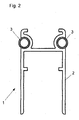
- FIGS. 1 to 5 illustrated sealing housing 1 have a housing part 2 and two attached thereto lateral sealing profiles 3.
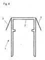
- the housing parts 2 are in the seal housings 1 according to the Fig. 1 . 4 and 5 identically formed.
- the housing parts are made of a cross-sectionally substantially U-shaped profile. On the inside of the mutually parallel legs each opposite a collar is formed, which serves to receive a movable sealing strip and the movable sealing strip and the housing part 2 connecting mechanism.
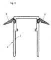
- the housing parts 2 of the seal housing 1 according to the Fig. 2 and 3 differ from the housing parts 2 of the seal housing 1 according to the FIGS. 1 . 4 and 5 in that on the housing parts 2 according to the Figures 2 and 3 Holding structures for the positive attachment of the lateral sealing profiles 3 has.
- Fig. 3 are undercut channels formed in the outer sides of the legs of the housing part 2, in which the lateral sealing profiles 3 are clipped or retracted with corresponding support structures.
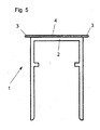
- the two lateral sealing profiles 3 are integrally connected to each other via a web 4.
- the lateral sealing profiles 3 of the seal housing 1, as shown in the Fig. 1 to 5 are shown is common that they protrude laterally beyond the housing part 2. Thus, they are suitable and adapted to seal an air gap between the outer sides of the legs of the housing parts 2 and the side walls of a groove in a door, so as to allow the passage of air, smoke and / or sound from one side of the door through this air gap on the prevent other side of the door.
- the lateral sealing profiles 3 are deformed after dem.EinTERa the seal in a groove of the door leaf, as in particular in comparison with the example of Fig. 6 is recognizable.
- the Fig. 6 shows the sealing of the air gap through the lateral sealing profiles 3 relative to the lateral wall of the groove 9 of the door leaf 5.
- a sealing strip is arranged, which is connected via a conventional mechanism with the housing part 2 of the seal housing 1.
- the sealing strip is automatically lowered over the mechanism when closing the door and automatically raised when the door is opened. Wear the sealing strips a total of three sealing profiles, the seal in the closed state of the door between the lower end of the door leaf 5 and the floor or between the upper end of the door leaf 5 and a frame or ceiling remaining gap.
- the seal housing 1 corresponds to the in Fig. 4 shown seal housing 1 largely.
Landscapes
- Engineering & Computer Science (AREA)
- Civil Engineering (AREA)
- Structural Engineering (AREA)
- Specific Sealing Or Ventilating Devices For Doors And Windows (AREA)
Abstract
Description
- Die Erfindung betrifft ein Dichtungsgehäuse für eine beim Schließen einer Tür oder eines Fensters selbsttätig auslösenden Dichtung zur Montage in einer Nut eines Türflügels oder eines Fensterflügels, mit einem Gehäuseteil, das einen Längsschlitz zum Anordnen eines beweglichen Dichtungsprofils der Dichtung aufweist. Die Erfindung betrifft ferner eine Dichtung zur Montage in einer Nut eines Türflügels einer Tür oder eines Fensterflügels eines Fensters, wobei die Dichtung geeignet und eingerichtet ist beim Schließen einer Tür oder eines Fensters selbsttätig auszulösen und abgesenkt zu werden, wobei die Dichtung ein Dichtungsgehäuse aufweist. Die Erfindung betrifft schließlich auch eine Anordnung aus einem Türflügel für eine Tür mit einer Nut und mit einer Dichtung, wobei in der Nut die beim Schließen der Tür selbsttätig auslösende Dichtung angeordnet ist.
- In großer Vielzahl werden Dichtungen mit selbsttätig beim Schließen der Tür absenkbaren Dichtungsprofilen bei Haustüren, Wohnungsabschlusstüren und Innentüren eingesetzt, um Zugluft, Schalleintritt und/oder Raucheintritt zu verhindern. Eine derartige Dichtung mit einem selbsttätig absenkbaren Dichtprofil ist beispielsweise aus der Patentschrift mit der Veröffentlichungsnummer
EP 1 460 232 B1 bekannt. Die in dieser Patentschrift offenbarte Dichtung wird wie auch viele andere Dichtungen in einer Nut am unteren Ende des Türflügels eingesetzt. Bei Holztüren, sei es aus Massivholz oder aus Türen mit einem massiven unteren Ende wird die Nut in das Holz eingefräst. Aufgrund von Feuchtigkeit oder aber aufgrund von anderen Einflüssen kann es zu Verformungen der Tür im Bereich der Nut kommen. Bekannt ist beispielsweise das Phänomen des sogenannten "Zuschnäbelns" der Nut. Als "Zuschnäbeln" wird bezeichnet, wenn sich das Holz im Bereich der Nut so verformt, dass die Nut eine geringere Breite im Bereich der Öffnung als im Nutgrund hat. Ebenso ist es bekannt, dass sich die Türen an den mit der Nut versehenen Enden in axialer Richtung der Nut bogenförmig verformen. Diese Arten von Verformungen behindern oder verhindern das Einsetzen einer Dichtung in die Nut. Es ist daher derzeit üblich, dass die Nuten in den unteren Enden der Türflügel breiter gefräst werden als dies nach den Außenabmessungen der Dichtung notwendig wäre. Es ist dann trotz der Verformungen im Bereich des Holzes im Bereich der Nut möglich, die Dichtung in die Nut einzusetzen. Es ist dabei selbstverständlich, dass sich das Holz dann nur in dem Toleranzbereich verformen kann, der durch die größere Ausfräsung der Nut über die Außenmaße der Dichtung vorgegeben ist. - Das größere Ausfräsen der Nut gegenüber den Außenmaßen der Dichtung führt jedoch dazu, dass nach erfolgter Montage der Dichtung in der Nut des Türflügels ein Luftspalt zwischen der Außenseite des Dichtungsgehäuses und den Seitenwänden der Nut verbleibt. Dieser Luftspalt ermöglicht allerdings einen Luftzug und einen Schall-und/oder Raucheintritt. Die Aufgabe der Dichtung war es jedoch, genau dieses zu verhindern.
- Der Erfindung lag vor dem Hintergrund der geschilderte Nachteil des Standes der Technik die Aufgabe zugrunde, ein Dichtungsgehäuse, eine Dichtung und eine Anordnung aus einem Türflügel und einer Dichtung so fortzuentwickeln, dass ein Luftzug oder ein Schall- oder Raucheintritt durch den Spalt zwischen der Dichtung und den Wänden der Nut nicht möglich ist.
- Diese Aufgabe wird erfindungsgemäß dadurch gelöst, dass an einer oder mehreren Außenseiten des Gehäuseteils des Dichtungsgehäuses sich in Längsrichtung erstreckende seitliche Dichtungsprofile angeordnet sind, die geeignet und eingerichtet sind, einen sich nach der Montage der Dichtung in der Nut zwischen den Außenseiten des Gehäuses ergebenen Luftspalt abzudichten. Diese seitlichen Dichtungsprofile legen sich dazu an die Wandungen der Nut an. Ein Luftzug oder ein Durchdringen von Schall oder Rauch ist damit verhindert. Ein Vorteil einer derartigen Dichtung ist, dass diese Dichtung jederzeit demontierbar und wieder montierbar ist, ohne dass für eine neue Abdichtung des Spalts zwischen den Wandungen der Nut und dem Dichtungsgehäuse gesorgt werden muss, da die seitlichen Dichtungsprofile ohne weiteres für ein erneutes Abdichten sorgen.
- Außerdem können die seitlichen Dichtungsprofile einer erfindungsgemäßen Dichtung nach der Montage der Dichtungen in Türen Änderungen der Spaltmaße ausgleichen, ohne dass es zu Undichtigkeiten kommt.
- Das erfindungsgemäße Dichtungsgehäuse kann so ausgebildet sein, dass die seitlichen Dichtungsprofile durch Formschluss mit dem Gehäuseteil des Dichtungsgehäuses verbunden sind. Die Dichtungsprofile können beispielsweise in das Gehäuseteil eingeklippst sein. Ebenso ist es möglich, dass die seitlichen Dichtungsprofile an dem Gehäuseteil angeklebt werden. Denkbar ist aber auch, dass die Dichtungsprofile zusammen mit dem Gehäuseteil oder Abschnitten des Gehäuseteils im Zweikomponentenverfahren stranggepresst sind. Dieses bietet sich insbesondere dann an, wenn sowohl die seitlichen Dichtungsprofile als auch das Gehäuseteil aus Kunststoff oder zumindest zum Teil aus Kunststoff hergestellt sind.
- Gemäß der Erfindung kann das Gehäuseteil ganz oder abschnittsweise aus Aluminium'und/oder Kunststoff bestehen.
- Die seitlichen Dichtungsprofile sind vorzugsweise aus einem Elastomer hergestellt. Sie können beispielsweise aus Schaumstoff bestehen.
- Zwei oder mehrere seitliche Dichtungsprofile eines erfindungsgemäßen Dichtungsgehäuses können miteinander verbunden sein. Die seitlichen Dichtungsprofile können ebenso aus einem einzigen Stück bestehen.
- Gemäß der Erfindung kann es sich bei den Dichtungsprofilen um Hohlpröfile oder um Dichtlippen handeln.
- Ein erfindungsgemäßes Dichtungsgehäuse bildet zusammen mit den anderen bekannten Komponenten, wie zum Beispiel der Dichtleiste und dem Mechanismus zum selbsttätigen Anheben der Dichtleiste eine erfindungsgemäße Dichtung. Eine derartige erfindungsgemäße Dichtung kann Befestigungswinkel umfassen, die zur Befestigung der Dichtung an einem Türflügel geeignet und eingerichtet sind. In einer bevorzugten Ausführung umfasst die Dichtung Befestigungsmittel, die vor der Montage der Dichtung in der Nut des Türflügels unverlierbar an dem Dichtungsgehäuse angeordnet sind.
- Eine derartige erfindungsgemäße Dichtung bildet zusammen mit einem Türflügel für eine Tür eine erfindungsgemäße Anordnung. Bei einer erfindungsgemäßen Anordnung kann die Tiefe der Nut größer sein als die Höhe des Gehäuseteils des Dichtungsgehäuses der Dichtung. Ist dies der Fall, kann die Dichtung im Nutgrund montiert sein. Ebenso ist es möglich, dass das Dichtungsgehäuse mit dem Rand der Nut abschließend montiert ist. Natürlich ist auch jede Montage in einer Position zwischen der Position des Dichtungsgehäuses im Nutgrund beziehungsweise am Nutrand möglich.
- Erfindungsgemäße Dichtungsgehäuse und eine erfindungsgemäße Anordnung aus einem Türflügel und einer erfindungsgemäßen Dichtung mit einem erfindungsgemäßen Dichtungsgehäuse sind anhand der Zeichnungen näher beschrieben. Es zeigt:
- Fig. 1 bis Fig. 5
- verschiedene Ausführungen von erfindungsgemäßen Dichtungsgehäusen und
- Fig. 6
- die erfindungsgemäße Anordnung.
- Die in den
Figuren 1 bis 5 dargestellten erfindungsgemäßen Dichtungsgehäuse 1 weisen ein Gehäuseteil 2 und jeweils zwei daran angebrachte seitliche Dichtungsprofile 3 auf. - Die Gehäuseteile 2 sind bei den Dichtungsgehäusen 1 gemäß den
Fig. 1 ,4 und5 identisch ausgebildet. Die Gehäuseteile sind aus einem im Querschnitt im Wesentlichen U-förmigen Profil hergestellt. Auf der Innenseite der parallel zueinander verlaufenden Schenkel ist einander gegenüberliegend jeweils ein Bund ausgebildet, der der Aufnahme einer beweglichen Dichtleiste und den die bewegliche Dichtleiste und das Gehäuseteil 2 verbindenden Mechanismus dient. - Die Gehäuseteile 2 der Dichtungsgehäuse 1 gemäß den
Fig. 2 und3 unterscheiden sich von den Gehäuseteilen 2 der Dichtungsgehäuse 1 gemäß denFiguren 1 ,4 und5 dadurch, dass an den Gehäuseteilen 2 gemäß denFiguren 2 und3 Haltestrukturen für die formschlüssige Befestigung der seitlichen Dichtungsprofile 3 aufweist. - Bei dem Ausführungsbeispiel gemäß
Fig. 2 sind Kanäle vorgesehen, in welche im Querschnitt ringförmige als Hohlprofile ausgebildete seitliche Dichtungsprofile 3 eingeklemmt sind. - Bei dem Ausführungsbeispiel gemäß
Fig. 3 sind in die Außenseiten der Schenkel des Gehäuseteils 2 hinterschnittene Kanäle eingeformt, in welche die seitlichen Dichtungsprofile 3 mit korrespondierenden Haltestrukturen eingeklippst oder eingezogen sind. - Bei den Ausführungsbeispielen gemäß
Fig, 1 ,4 und5 sind die seitlichen Dichtungsprofile an den Gehäuseteilen 2 angeklebt. - Beim Ausführungsbeispiel gemäß
Fig. 5 sind die beiden seitlichen Dichtungsprofile 3 über einen Steg 4 einstückig miteinander verbunden. - Den seitlichen Dichtungsprofilen 3 der Dichtungsgehäuse 1, wie sie in den
Fig. 1 bis 5 dargestellt sind, ist gemeinsam, dass sie seitlich über das Gehäuseteil 2 hinausragen. Damit sind sie geeignet und eingerichtet, einen Luftspalt zwischen den Außenseiten der Schenkel der Gehäuseteile 2 und den Seitenwänden einer Nut in einem Türflügel abzudichten, um so den Durchtritt von Luft, Rauch und/oder Schall von der einen Seite der Tür durch diesen Luftspalt auf die andere Seite der Tür zu verhindern. Die seitlichen Dichtungsprofile 3 sind nach dem.Einsetzen der Dichtung in eine Nut des Türflügels verformt, wie insbesondere auch im Vergleich mit dem Beispiel derFig. 6 erkennbar ist. - Die
Fig. 6 zeigt die Abdichtung des Luftspaltes durch die seitlichen Dichtprofile 3 gegenüber der seitlichen Wand der Nut 9 des Türflügels 5. In dem Dichtungsgehäuse ist eine Dichtleiste angeordnet, die über einen üblichen Mechanismus mit dem Gehäuseteil 2 des Dichtungsgehäuses 1 verbunden ist. Die Dichtleiste ist über dem Mechanismus beim Schließen der Tür automatisch absenkbar und beim Öffnen der Tür automatisch anhebbar. Die Dichtleisten tragen insgesamt drei Dichtprofile, die im geschlossenen Zustand der Tür einen zwischen dem unteren Ende des Türflügels 5 und dem Fußboden oder aber zwischen dem oberen Ende des Türflügels 5 und einer Zarge oder einer Decke verbleibenden Spalt abzudichten. - Das Dichtungsgehäuse 1 entspricht dem in
Fig. 4 dargestellten Dichtungsgehäuse 1 weitgehend.
Claims (19)
- Dichtungsgehäuse (1) für eine beim Schließen einer Tür oder eines Fensters selbsttätig auslösenden Dichtung (6) zur Montage in einer Nut (9) eines Türflügels (5) oder eines Fensterflügels, mit einem Gehäuseteil (2), das einen Längsschlitz (8) zum Anordnen zumindest eines beweglichen Dichtungsprofils (7) der Dichtung (6) aufweist,
dadurch gekennzeichnet, dass
an einer oder mehreren Außenseiten des Gehäuseteils (2) sich in Längsrichtung erstreckende seitliche Dichtungsprofile (3) angeordnet sind, die geeignet und eingerichtet sind, einen sich nach der Montage der Dichtung (6) in der Nut (9) zwischen den Außenseiten des Gehäuseteils (2) ergebenden Luftspalt (8) abzudichten. - Dichtungsgehäuse (1) nach Anspruch 1, dadurch gekennzeichnet, dass die seitlichen Dichtungsprofile (3) durch Formschluss mit dem Gehäuseteil (2) verbunden sind.
- Dichtungsgehäuse (1) nach Anspruch 1, dadurch gekennzeichnet, dass die seitlichen Dichtungsprofile (3) durch Kleben mit dem Gehäuseteil (2) verbunden sind.
- Dichtungsgehäuse (1) nach Anspruch 1, dadurch gekennzeichnet, dass die seitlichen Dichtungsprofile (3) zusammen mit dem Gehäuseteil (2) oder Abschnitten des Gehäuseteils (2) im Zwei-Komponenten-Verfahren stranggepresst sind.
- Dichtungsgehäuse (1) nach einem der Ansprüche 1 bis 4, dadurch gekennzeichnet, dass das Gehäuseteil (2) ganz oder abschnittsweise aus Aluminium besteht.
- Dichtungsgehäuse (1) nach einem der Ansprüche 1 bis 5, dadurch gekennzeichnet, dass das Gehäuseteil (2) ganz oder abschnittsweise aus Kunststoff besteht.
- Dichtungsgehäuse (1) nach einem der Ansprüche 1 bis 6, dadurch gekennzeichnet, dass die seitlichen Dichtungsprofile (3) aus einem Elastomer bestehen.
- Dichtungsgehäuse (1) nach einem der Ansprüche 1 bis 7, dadurch gekennzeichnet, dass die seitlichen Dichtungsprofile (3) aus Schaumstoff bestehen.
- Dichtungsgehäuse (1) nach einem der Ansprüche 1 bis 8, das die seitlichen Dichtungsprofile (3) miteinander verbunden sind.
- Dichtungsgehäuse (1) nach einem der Ansprüche 1 bis 9, dadurch gekennzeichnet, dass die seitlichen Dichtungsprofile (3) aus einem Stück bestehen.
- Dichtungsgehäuse (1) nach einem der Ansprüche 1 bis 10, dadurch gekennzeichnet, dass die Dichtungsprofile (3) Hohlprofile sind.
- Dichtungsgehäuse (1) nach einem der Ansprüche 1 bis 11, dadurch gekennzeichnet, dass die Dichtungsprofile (3) Dichtlippen sind.
- Dichtung (6) zur Montage in einer Nut (9) eines Türflügels (5) einer Tür oder eines Fensterflügels eines Fensters, wobei die Dichtung (6) geeignet und eingerichtet ist beim Schließen einer Tür oder eines Fensters selbsttätig auszulösen und die Dichtung (6) ein Dichtungsgehäuse (1) aufweist,
dadurch gekennzeichnet, dass
das Dichtungsgehäuse (1) nach einem der Ansprüche 1 bis 12 ausgebildet ist. - Dichtung (6) nach Anspruch 13, dadurch gekennzeichnet, dass die Dichtung (6) Befestigungswinkel umfasst, die zur Befestigung der Dichtung (6) an einem Türflügel (5) geeignet und eingerichtet sind.
- Dichtung (6) nach Anspruch 13 oder 14, dadurch gekennzeichnet, dass die Dichtung (6) Befestigungsmittel umfasst, die vor der Montage der Dichtung in der Nut (9) des Türflügels (5) unverlierbar an dem Dichtungsgehäuse (1) angeordnet sind.
- Anordnung aus einem Türflügel (5) für eine Tür mit einer Nut (9) und mit einer Dichtung (6), wobei in der Nut (9) die beim Schließen der Tür selbsttätig auslösende Dichtung (6) angeordnet ist,
dadurch gekennzeichnet, dass
die Dichtung (6) nach Anspruch 13 ausgebildet ist. - Anordnung nach Anspruch 14, dadurch gekennzeichnet, dass die Tiefe der Nut (9) größer in als die Höhe des Gehäuseteils (2) des Dichtungsgehäuses (1) der Dichtung (6).
- Anordnung nach Anspruch 15, dadurch gekennzeichnet, dass die Dichtung (6) im Nutgrund montiert ist.
- Anordnung nach Anspruch 15, dadurch gekennzeichnet, dass das Dichtungsgehäuse (1) mit dem Rand der Nut (9) abschließend montiert ist.
Applications Claiming Priority (1)
| Application Number | Priority Date | Filing Date | Title |
|---|---|---|---|
| DE200720006336 DE202007006336U1 (de) | 2007-05-03 | 2007-05-03 | Dichtungsgehäuse und Dichtung mit seitlichen Dichtungsprofilen |
Publications (2)
| Publication Number | Publication Date |
|---|---|
| EP1988248A2 true EP1988248A2 (de) | 2008-11-05 |
| EP1988248A3 EP1988248A3 (de) | 2010-12-22 |
Family
ID=38375414
Family Applications (1)
| Application Number | Title | Priority Date | Filing Date |
|---|---|---|---|
| EP08007444A Withdrawn EP1988248A3 (de) | 2007-05-03 | 2008-04-16 | Dichtungsgehäuse und Dichtung mit seitlichen Dichtungsprofilen |
Country Status (2)
| Country | Link |
|---|---|
| EP (1) | EP1988248A3 (de) |
| DE (1) | DE202007006336U1 (de) |
Cited By (1)
| Publication number | Priority date | Publication date | Assignee | Title |
|---|---|---|---|---|
| EP2554774A1 (de) | 2011-08-02 | 2013-02-06 | Planet GDZ AG | Dichtung für eine schwellenlose Tür |
Families Citing this family (2)
| Publication number | Priority date | Publication date | Assignee | Title |
|---|---|---|---|---|
| IT1393882B1 (it) * | 2009-04-29 | 2012-05-11 | Geron | Assieme di fissaggio per guarnizioni |
| NL2012920B1 (nl) * | 2014-05-30 | 2016-06-09 | Elton Bv | Deurafdichting, deur met deurafdichting en werkwijze voor het vervaardigen daarvan. |
Citations (1)
| Publication number | Priority date | Publication date | Assignee | Title |
|---|---|---|---|---|
| EP1460232B1 (de) | 2003-03-19 | 2006-08-23 | Manfred Kross | Bodendichtung in einem Türblatt |
Family Cites Families (2)
| Publication number | Priority date | Publication date | Assignee | Title |
|---|---|---|---|---|
| DE3237524C2 (de) * | 1982-10-09 | 1986-08-07 | Fa. F. Athmer, 5760 Arnsberg | Fußbodenseitige Türdichtungsvorrichtung |
| ATE553277T1 (de) * | 2003-05-08 | 2012-04-15 | Roto Gluske Bkv Gmbh | Bodendichtung mit federband |
-
2007
- 2007-05-03 DE DE200720006336 patent/DE202007006336U1/de not_active Expired - Lifetime
-
2008
- 2008-04-16 EP EP08007444A patent/EP1988248A3/de not_active Withdrawn
Patent Citations (1)
| Publication number | Priority date | Publication date | Assignee | Title |
|---|---|---|---|---|
| EP1460232B1 (de) | 2003-03-19 | 2006-08-23 | Manfred Kross | Bodendichtung in einem Türblatt |
Cited By (3)
| Publication number | Priority date | Publication date | Assignee | Title |
|---|---|---|---|---|
| EP2554774A1 (de) | 2011-08-02 | 2013-02-06 | Planet GDZ AG | Dichtung für eine schwellenlose Tür |
| EP2840221A1 (de) | 2011-08-02 | 2015-02-25 | Planet GDZ AG | Dichtung für eine schwellenlose Türe |
| EP2843176A1 (de) | 2011-08-02 | 2015-03-04 | Planet GDZ AG | Dichtung für eine schwellenlose Tür |
Also Published As
| Publication number | Publication date |
|---|---|
| EP1988248A3 (de) | 2010-12-22 |
| DE202007006336U1 (de) | 2007-08-16 |
Similar Documents
| Publication | Publication Date | Title |
|---|---|---|
| EP2921634B1 (de) | Dichtung für Türen zum Abdichten eines Luftspaltes zwischen einem Türflügel einerseits und einem Türahmen, einem Fußboden, einer Zimmerdecke, einem Sturz o.ä. andererseits | |
| EP1936097B1 (de) | Türdichtungssystem | |
| EP3259428B1 (de) | Dichtungsvorrichtung für fenster- und türelemente | |
| EP2088275B1 (de) | Seitendichtungsprofil insbesondere für Rahmenprofile und damit ausgestattete Schiebetüranlagen | |
| DE1509553A1 (de) | Fensterkonstruktion | |
| EP4299870A1 (de) | Blendrahmen für eine tür mit extrusionsrahmen und schwelle, tür mit einem derartigen blendrahmen und verfahren zur herstellung dieser tür | |
| EP1988248A2 (de) | Dichtungsgehäuse und Dichtung mit seitlichen Dichtungsprofilen | |
| EP3165701A1 (de) | Belüftungselement für fenster mit als schikane wirkender klappe | |
| EP3019684B1 (de) | Türdichtungssystem | |
| DE10207157B4 (de) | Verbindungselement zur stirnseitigen Verbindung von zwei Teilen | |
| EP4345239A1 (de) | Rahmen zum einfassen mindestens einer scheibe und vorrichtung umfassend den rahmen und eine zarge | |
| EP1863999B1 (de) | Flügel einer tür oder eines fensters | |
| DE102011008765A1 (de) | Profilanordnung, Rahmen und Rahmenanordnung | |
| EP2072744B1 (de) | Zargenprofil für eine Hebe-Schiebetür | |
| CH711428B1 (de) | Modulares System für Schränke und/oder Regale. | |
| EP2666952B1 (de) | Tür- oder Fensterfugenabdichtungsprofil | |
| DE8601985U1 (de) | Torblatt mit Belüftungsöffnungen | |
| EP2060726A2 (de) | Hohlkammerprofil | |
| DE19753638C2 (de) | Blend- oder Flügelrahmen für Fenster oder Türen | |
| AT510431B1 (de) | Blindzarge | |
| EP2426302B1 (de) | Türzarge, insbesondere für Brandschutzzwecke | |
| DE10322029B4 (de) | Profilsystem | |
| DE102015102582B3 (de) | Vorsatztür oder -fenster, insbesondere Insektenschutztür oder -fenster | |
| DE102016102606A1 (de) | Profil für Fenster- und Türrahmen | |
| DE2541040A1 (de) | Schaukasten |
Legal Events
| Date | Code | Title | Description |
|---|---|---|---|
| PUAI | Public reference made under article 153(3) epc to a published international application that has entered the european phase |
Free format text: ORIGINAL CODE: 0009012 |
|
| AK | Designated contracting states |
Kind code of ref document: A2 Designated state(s): AT BE BG CH CY CZ DE DK EE ES FI FR GB GR HR HU IE IS IT LI LT LU LV MC MT NL NO PL PT RO SE SI SK TR |
|
| AX | Request for extension of the european patent |
Extension state: AL BA MK RS |
|
| PUAL | Search report despatched |
Free format text: ORIGINAL CODE: 0009013 |
|
| AK | Designated contracting states |
Kind code of ref document: A3 Designated state(s): AT BE BG CH CY CZ DE DK EE ES FI FR GB GR HR HU IE IS IT LI LT LU LV MC MT NL NO PL PT RO SE SI SK TR |
|
| AX | Request for extension of the european patent |
Extension state: AL BA MK RS |
|
| AKY | No designation fees paid | ||
| REG | Reference to a national code |
Ref country code: DE Ref legal event code: R108 |
|
| REG | Reference to a national code |
Ref country code: DE Ref legal event code: R108 Effective date: 20110831 |
|
| STAA | Information on the status of an ep patent application or granted ep patent |
Free format text: STATUS: THE APPLICATION IS DEEMED TO BE WITHDRAWN |
|
| 18D | Application deemed to be withdrawn |
Effective date: 20110623 |