EP1988376B1 - Dispositif de roulement à rouleaux avec capteur - Google Patents
Dispositif de roulement à rouleaux avec capteur Download PDFInfo
- Publication number
- EP1988376B1 EP1988376B1 EP08008132.6A EP08008132A EP1988376B1 EP 1988376 B1 EP1988376 B1 EP 1988376B1 EP 08008132 A EP08008132 A EP 08008132A EP 1988376 B1 EP1988376 B1 EP 1988376B1
- Authority
- EP
- European Patent Office
- Prior art keywords
- displacement
- detector
- peripheral surface
- displacement detector
- outer peripheral
- Prior art date
- Legal status (The legal status is an assumption and is not a legal conclusion. Google has not performed a legal analysis and makes no representation as to the accuracy of the status listed.)
- Ceased
Links
- 238000005096 rolling process Methods 0.000 title claims description 150
- 238000006073 displacement reaction Methods 0.000 claims description 592
- 238000001514 detection method Methods 0.000 claims description 230
- 230000002093 peripheral effect Effects 0.000 claims description 182
- 229910000976 Electrical steel Inorganic materials 0.000 claims description 9
- 229910000831 Steel Inorganic materials 0.000 claims description 5
- 239000000463 material Substances 0.000 claims description 5
- 239000010959 steel Substances 0.000 claims description 5
- 125000006850 spacer group Chemical group 0.000 description 39
- 238000012545 processing Methods 0.000 description 29
- 238000000034 method Methods 0.000 description 21
- 238000004519 manufacturing process Methods 0.000 description 16
- 230000035945 sensitivity Effects 0.000 description 15
- 230000014509 gene expression Effects 0.000 description 11
- 230000008859 change Effects 0.000 description 8
- 239000011159 matrix material Substances 0.000 description 7
- 238000010586 diagram Methods 0.000 description 6
- 238000012937 correction Methods 0.000 description 5
- 230000007423 decrease Effects 0.000 description 5
- 230000003321 amplification Effects 0.000 description 4
- 230000000694 effects Effects 0.000 description 4
- 230000004907 flux Effects 0.000 description 4
- 238000003780 insertion Methods 0.000 description 4
- 230000037431 insertion Effects 0.000 description 4
- 238000003199 nucleic acid amplification method Methods 0.000 description 4
- 230000036316 preload Effects 0.000 description 4
- 238000007789 sealing Methods 0.000 description 4
- 239000003990 capacitor Substances 0.000 description 3
- 230000015556 catabolic process Effects 0.000 description 3
- 238000006731 degradation reaction Methods 0.000 description 3
- 230000035699 permeability Effects 0.000 description 3
- 238000005299 abrasion Methods 0.000 description 2
- 229920003023 plastic Polymers 0.000 description 2
- 239000004033 plastic Substances 0.000 description 2
- 239000000843 powder Substances 0.000 description 2
- 230000008569 process Effects 0.000 description 2
- 230000004044 response Effects 0.000 description 2
- OKTJSMMVPCPJKN-UHFFFAOYSA-N Carbon Chemical compound [C] OKTJSMMVPCPJKN-UHFFFAOYSA-N 0.000 description 1
- 241000123069 Ocyurus chrysurus Species 0.000 description 1
- 230000004323 axial length Effects 0.000 description 1
- 229910052799 carbon Inorganic materials 0.000 description 1
- 239000000470 constituent Substances 0.000 description 1
- 238000011161 development Methods 0.000 description 1
- 230000018109 developmental process Effects 0.000 description 1
- 230000005674 electromagnetic induction Effects 0.000 description 1
- 238000005498 polishing Methods 0.000 description 1
- 238000003825 pressing Methods 0.000 description 1
- 239000000725 suspension Substances 0.000 description 1
- 230000009466 transformation Effects 0.000 description 1
Images


Classifications
-
- G—PHYSICS
- G01—MEASURING; TESTING
- G01L—MEASURING FORCE, STRESS, TORQUE, WORK, MECHANICAL POWER, MECHANICAL EFFICIENCY, OR FLUID PRESSURE
- G01L5/00—Apparatus for, or methods of, measuring force, work, mechanical power, or torque, specially adapted for specific purposes
- G01L5/0009—Force sensors associated with a bearing
- G01L5/0023—Force sensors associated with a bearing by using magnetic sensors
-
- F—MECHANICAL ENGINEERING; LIGHTING; HEATING; WEAPONS; BLASTING
- F16—ENGINEERING ELEMENTS AND UNITS; GENERAL MEASURES FOR PRODUCING AND MAINTAINING EFFECTIVE FUNCTIONING OF MACHINES OR INSTALLATIONS; THERMAL INSULATION IN GENERAL
- F16C—SHAFTS; FLEXIBLE SHAFTS; ELEMENTS OR CRANKSHAFT MECHANISMS; ROTARY BODIES OTHER THAN GEARING ELEMENTS; BEARINGS
- F16C19/00—Bearings with rolling contact, for exclusively rotary movement
- F16C19/52—Bearings with rolling contact, for exclusively rotary movement with devices affected by abnormal or undesired conditions
- F16C19/522—Bearings with rolling contact, for exclusively rotary movement with devices affected by abnormal or undesired conditions related to load on the bearing, e.g. bearings with load sensors or means to protect the bearing against overload
-
- F—MECHANICAL ENGINEERING; LIGHTING; HEATING; WEAPONS; BLASTING
- F16—ENGINEERING ELEMENTS AND UNITS; GENERAL MEASURES FOR PRODUCING AND MAINTAINING EFFECTIVE FUNCTIONING OF MACHINES OR INSTALLATIONS; THERMAL INSULATION IN GENERAL
- F16C—SHAFTS; FLEXIBLE SHAFTS; ELEMENTS OR CRANKSHAFT MECHANISMS; ROTARY BODIES OTHER THAN GEARING ELEMENTS; BEARINGS
- F16C19/00—Bearings with rolling contact, for exclusively rotary movement
- F16C19/02—Bearings with rolling contact, for exclusively rotary movement with bearing balls essentially of the same size in one or more circular rows
- F16C19/14—Bearings with rolling contact, for exclusively rotary movement with bearing balls essentially of the same size in one or more circular rows for both radial and axial load
- F16C19/18—Bearings with rolling contact, for exclusively rotary movement with bearing balls essentially of the same size in one or more circular rows for both radial and axial load with two or more rows of balls
- F16C19/181—Bearings with rolling contact, for exclusively rotary movement with bearing balls essentially of the same size in one or more circular rows for both radial and axial load with two or more rows of balls with angular contact
- F16C19/183—Bearings with rolling contact, for exclusively rotary movement with bearing balls essentially of the same size in one or more circular rows for both radial and axial load with two or more rows of balls with angular contact with two rows at opposite angles
- F16C19/184—Bearings with rolling contact, for exclusively rotary movement with bearing balls essentially of the same size in one or more circular rows for both radial and axial load with two or more rows of balls with angular contact with two rows at opposite angles in O-arrangement
- F16C19/186—Bearings with rolling contact, for exclusively rotary movement with bearing balls essentially of the same size in one or more circular rows for both radial and axial load with two or more rows of balls with angular contact with two rows at opposite angles in O-arrangement with three raceways provided integrally on parts other than race rings, e.g. third generation hubs
-
- F—MECHANICAL ENGINEERING; LIGHTING; HEATING; WEAPONS; BLASTING
- F16—ENGINEERING ELEMENTS AND UNITS; GENERAL MEASURES FOR PRODUCING AND MAINTAINING EFFECTIVE FUNCTIONING OF MACHINES OR INSTALLATIONS; THERMAL INSULATION IN GENERAL
- F16C—SHAFTS; FLEXIBLE SHAFTS; ELEMENTS OR CRANKSHAFT MECHANISMS; ROTARY BODIES OTHER THAN GEARING ELEMENTS; BEARINGS
- F16C2326/00—Articles relating to transporting
- F16C2326/01—Parts of vehicles in general
- F16C2326/02—Wheel hubs or castors
Definitions
- the invention relates to a rolling bearing device with a sensor having raceway members, rolling elements, and a sensor unit, and particularly, to a hub unit having a sensor unit.
- This hub unit includes a rotating raceway ring, a fixed raceway ring, and one displacement sensor, and the displacement sensor is provided in the fixed raceway ring.
- an outer peripheral surface of the fixed raceway ring has a hole that extends radially, and the displacement sensor is inserted into the hole.
- a detection surface of the displacement sensor is directed to an outer peripheral surface of the rotating raceway ring.
- the displacement sensor detects a gap between the rotating raceway ring and the fixed raceway ring that changes depending on any displacement of the outer peripheral surface of the rotating raceway ring to be generated when a load acts on a wheel of a vehicle (specifically, an electric signal that changes in response to this gap).
- the hub unit calculates a vertical load that acts on the wheel on the basis of a gap detected by the displacement sensor.
- the request for improve the sensitivity of the sensor unit to precisely measure the load applied to a rolling bearing exists in the rolling bearing device with a sensor.
- US 6 471 407 B1 discloses a rolling bearing unit for supporting a wheel, comprising a stationary race which has a stationary peripheral surface formed with a stationary raceway, being not rotatable during use, and supported by a suspension, a rotatable race which has a rotatable peripheral surface formed with a rotatable raceway, being rotatable with the wheel fixed thereto, rolling elements which are rotatably provided between the stationary raceway and rotatable raceway, a vibration sensor which is supported by the stationary race, a sensor rotor which is supported by the rotatable race and has circumferential characteristics changing alternately and a rotation speed sensor which is supported by the stationary race and has a detection portion facing the sensor rotor.
- US 2007/058892 A1 discloses a rolling bearing device according to the preamble part of claim 1.
- the object of the invention is to provide a rolling bearing device with a sensor capable of finding moment loads and axial translational loads that act on a raceway member with high sensitivity.
- the present invention provides the following arrangements.
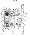
- Fig. 1 is an axial sectional view of a hub unit that is a first embodiment of a rolling bearing device with a sensor of the invention.
- the axial end surface of the inner ring 2 on the side of the large-diameter shaft portion 21 abuts on the stepped portion 22.
- a nut 63 serving as a first tubular portion is screwed to the thread of the small-diameter shaft portion 19.
- An axial end surface of the inner ring 2 opposite the large-diameter shaft portion 21 abuts on an axial end surface of the nut 63 on the side of the large-diameter shaft portion 21.
- the outer ring 3 is located radially outside the large-diameter shaft portion 21.
- An inner peripheral surface of the outer ring 3 has an angular first raceway groove 44 serving as a raceway surface, and an angular second raceway groove 45 serving as a raceway surface.
- the outer ring 3 has a body-attaching flange 75 for fixation to a vehicle body.
- the sensor unit 10 has a first displacement detector 70, a second displacement defector 71, and a target member 73.
- the first and second displacement detectors 70 and 71 are fixed to an inner peripheral surface of the tubular member 52.
- the target member 73 is composed of a nut 63 serving as a first tubular member, a first spacer 190 serving as a third tubular member, a second tubular member 191, a second spacer 192 serving as the third tubular member, and a fixing nut 193.
- the second tubular member 191 is formed by axially stacking a plurality of silicon steel plates without any gap.
- the second tubular member 191 is externally fitted and fixed to the outer peripheral surface of the nut 63 by press fitting.
- An axial end surface of the second tubular member 191 on the side of the inner ring 2 abuts on an axial end surface of the first spacer 190 opposite the inner ring 2.
- the second spacer 192 is made of a nonmagnetic material, such as plastics.
- the second spacer 192 is externally fitted and fixed to the outer peripheral surface of the nut 63 by press fitting.
- An axial end surface of the second spacer 190 on the side of the inner ring 2 abuts on an axial end surface of the second tubular member 191 opposite the inner ring 2.
- the outer diameter of an outer peripheral surface of the first spacer 190 is made approximately equal to the outer diameter of an outer peripheral surface of the second spacer 192, while the outer diameter of the outer peripheral surface of the first spacer 190 is madder smaller than the outer diameter of an outer peripheral surface of the second tubular member 191.
- the outer peripheral surface of the first spacer 190 is connected to the outer peripheral surface of the second tubular member 191 via a stepped portion, and the outer peripheral surface of the second tubular member 191 is connected to the outer peripheral surface of the second spacer 192. via a stepped portion.
- the inner shaft 1, the inner ring 2, and the target member 73 constitute the second raceway member, while the outer peripheral surface of the first spacer 190, the outer peripheral surface of the second tubular member 191, and the outer peripheral surface of the second spacer 192 constitute a displacement-detected portion.
- the nut 63 is adapted to move on the small-diameter shaft portion 19 axially toward the middle-diameter shaft portion 20 as it is fastened using a hexagonal wrench that is a fastening tool.
- the sensor unit 10 has a first displacement detector 70, and a second displacement detector 71.
- the first and second displacement detectors 70 and 71 are fixed to the inner peripheral surface of the tubular member 52.
- the first displacement detector 70 is located closer to the lid member 53 in the axial direction than the second displacement detector 71.
- the first displacement detector 70 is located at a distance axially from the second displacement detector 71.
- the first displacement detector 70 substantially overlaps the second displacement detector 71 axially.
- the first displacement detector 70 has a sensor ring 83, and four displacement sensors 84
- the second displacement detector 71 has a sensor ring 93 and four displacement sensors 94.
- the sensor ring 83 and the sensor ring 93 are fixed to a flange 57 of the tubular member 52 by locking screws 59 with an annular spacer 58 interposed therebetween.
- Fig. 3 is a view illustrating a circumferential arrangement configuration, of the four displacement sensors 84.
- the four displacement sensors 94 also have the same circumferential arrangement structure as the four displacement sensors 84.
- reference number 75 in Fig. 3 denotes a flange of the .outer ring 3 denoted by 75 in Fig. 1 .
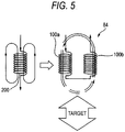
- each of the displacement sensors 84 is composed of a coil element 100a and a coil element 100b that are arranged in proximity to each other in the circumferential direction, to make a pair.
- the four displacement sensors 84 are installed in a position that substantially radially faces the portion of the target member 73 that is located on the vertical topmost side, a position that substantially radially faces the portion of the target member 73 that is located on the vertical bottommost side, a position that substantially radially faces the foremost position of a vehicle to which a rolling bearing device is attached in the target member 73, and a position that substantially radially faces the rearmost position of the vehicle to which the rolling bearing device is attached in the target member 73, in a state where the rolling bearing device (hub unit in the first embodiment) is installed in a predetermined position.
- the four displacement sensors 84 substantially overlap the four displacement sensors 94 axially.
- two sets of coil elements 100a and coil elements 100b that are located in the vertical direction are connected to an oscillator 130.
- An alternating current during a fixed period is supplied to the two sets of coil elements 100a and coil elements 100b from the oscillator 130.
- a synchronizing capacitor 131 is connected in parallel to the two sets of coil elements 100a and the coil elements 100b.
- an axial central portion of the detection surface A1 of the displacement sensor 84 substantially faces a contact portion between the second spacer 192 and the second tubular member 191 radially, while an axial central portion of the detection surface A2 of the displacement sensor 94 substantially faces a contact portion between the first spacer 190 and the second tubular member 191 radially.
- a front-and-rear horizontal direction of the wheel is defined as an x-axis direction
- a right-and-left horizontal direction (axial direction) of the wheel is defined as a y-axis direction
- an up-and-down direction of the wheel is defined as a z-axis direction.
- a suffix "i" is used for displacement detection values of the four displacement sensors 84 on the inner side
- a suffix "o” is used for the four displacement sensors 94 on the outer side.
- a sensor 84 installed in a position that substantially radially faces the foremost position of a vehicle to which the hub unit is attached in the target member 73 is called sensor 84f ("f" is an abbreviation of "front")
- a sensor 84 installed in a position that substantially radially faces the rearmost position of the vehicle to which the hub unit is attached in the target member 73 is called sensor 84r (“r” is an abbreviation of "rear")
- a sensor 84 installed in a position that substantially radially faces the portion of the target member 73 that is located on the vertical topmost side is called sensor 84t (“t” is an abbreviation of "top”)
- a sensor 84 installed in a position that substantially radially faces the portion of the target member 73 that is located on the vertical bottommost side is called sensor 84b (“b” is an abbreviation of "bottom”).
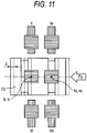
- Fig. 11 is a view schematically showing the positional relationship between the target member 73 and some displacement sensors in a case where a translational load Fy in the y-axis direction has acted on the wheel.
- an independent variable (sFy) corresponding to the translational load Fy in the y-axis direction will be explained with reference to Fig. 11 .
- Displacement detection values of displacement in the x-axis direction, and displacement detection values of displacement in the z-axis direction are found as follows.
- a difference between a displacement detection value f of a front sensor and a displacement detection value r of a rear sensor is defined as a displacement detection value of displacement in the x-axis direction
- a difference between a displacement detection value t of a top sensor and a displacement detection value b of a bottom sensor is defined as a displacement detection value of displacement in the z-axis direction. Since temperature affects outputs of the front and rear sensors and outputs of the top and bottom sensors, respectively, by the same amount in the same direction, a temperature drift is eliminated by taking differences as described above.
- displacement sensors 84t, 84b, 84f, 84r, 94t, 94b, 94f and 94r are arranged on the inner side and on the outer side.
- displacement detection values of displacement in the x-axis direction and displacement detection values of displacement in the z-axis direction are acquired.
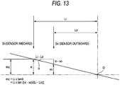
- Fig. 13 is a view showing the relationship of various variables in the state of pure moment where only the moment load Mz around the z-axis acts.
- the independent variable (sMx) corresponding to the moment load Mx around the x-axis direction is found as follows.
- kx in the Expression (4) is a value defined in Fig. 15 , is a correction coefficient introduced to the same effect as kz, and is a correction coefficient obtained by dividing the inclination of a zi straight line by the inclination of an mx straight line.
- This kx is calculated from a view showing the relationship between Mx, and displacement detection values of mx and zi in a case where only the moment load Mx around the x-axis is made to act, like 16.
- the first displacement detector 70 and the second displacement detector 71 that are spaced axially from each other are provided. Therefore, not only translational loads based on axial translational displacement can be calculated on the basis of a detection signal of the first displacement detector 70, and a detection signal of the second displacement detection signal 71, but also changes in displacement depending on the axial position of the rolling bearing device can be detected, and moment loads that act on the rolling bearing device can be calculated on the basis of the change in displacement. Further, since the moment loads that act on the wheel in addition to the translational loads that act on the hub unit can be calculated, operation control during traveling of a vehicle can be precisely performed.
- the second tubular member 191 is formed by axially stacking a plurality of silicon steel plates.
- an eddy current is not generated in the second tubular member 191 in the middle of detection of displacement of a displacement-detected portion using the law of electromagnetic induction. Accordingly, the energy loss when a displacement signal is acquired can be reduced, and the sensitivity of the displacement detectors can be enhanced.
- the second tubular portion has a structure in which magnetic properties are good, passage of magnetic fluxes is easy, and an eddy current is hardly generated, i.e., a structure in which silicon steel plates are axially stacked, the loss of an electric signal resulting from the generation of an eddy current can be reduced, and the sensitivity of the sensors can be made high.
- the eight displacement sensors 84t, 84b, 84f, 84r, 94t, 94b, 94f, and 94r can be simply fixed to the rolling bearing device only by fixing the case member 6 to the outer peripheral surface of the outer ring 1.
- the target member 73 in the sensor unit 10 can be simply fixed to the inner shaft 1 and the inner ring 2.
- the positions of the first and second displacement detectors 70 and 71 relative to the case member 6 will be determined precisely in advance. Accordingly, positioning of the sensor unit 10 to the target member 73 can be made precisely and easily, and the sensor unit 10 can be easily mounted to the hub unit.
- both two raceway grooves may be formed not in the inner ring but in the inner shaft.
- the rolling bearing device is a hub unit
- the rolling bearing devices with a sensor of this invention is not limited the hub unit, and may be any kinds of bearing devices, such as a magnetic bearing device (turbo molecular pump), other than the hub unit. This is because it is needless to say that the configuration of the invention described in the first embodiment can be applied to various bearing devices with the needs for measuring a plurality of moment loads or translational loads.
- the rolling elements of a rolling bearing with a sensor to be manufactured are balls.
- the rolling elements of the rolling bearing with a sensor to be manufactured may be rollers or may include rollers and balls.
- the hexagonal wrench insertion hole 205 opened to one axial end surface of the nut 63 is formed in the nut 63.
- an engaging hole such as a torque wrench insertion hole opened to one axial end surface of the nut, other than the hexagonal wrench insertion hole opened to one axial end surface of the nut, is formed in the nut.
- a sealing unit (not shown) that extends radially is installed between a raceway surface axially closest to a target member, and the target member and the displacement-detected portion of the target member 73 is cut and polished in a state where the target member 73 is fixed to the inner shaft 1 when the displacement-detected portion is processed, any variation in the precision of respective members at the time of processing can be canceled, and processing precision can be made high.
- a sealing unit (not shown) that extends radially is installed between a raceway surface axially closest to a target member, and the target member, and the displacement-detected portion of the target member 73 is cut and polished in a state where the target member 73 is fixed to the inner shaft 1 and the inner shaft 1 is rotated when the displacement-detected portion is processed, the runout (decentering) of the rolling bearing device can be suppressed; which is more preferable.
- a second embodiment of the present invention will be described with reference to Figs. 20 to 33 .
- the portions which are the same as those portions in the first embodiment ( Figs. 1 to 19 ) will be denoted with the same reference numerals, and a portion of the description will be omitted.
- Fig. 20 is an axial sectional view of a hub unit of a rolling bearing device according to the second embodiment of the invention.
- An outer peripheral surface of the inner ring 2 has a cylindrical outer peripheral surface 26 at the opposite side of large-diameter shaft portion 21 in the axial direction.
- the cylindrical outer peripheral surface 26 communicates through a step portion 30 to a raceway shoulder portion 29 located at the opposite side of the large-diameter shaft portion 21 of the raceway groove 28.
- the raceway shoulder portion 29 has a cylindrical outer peripheral surface 35.
- An outer diameter of the cylindrical outer surface 26 located at the axial end of the outer peripheral surface of the inner ring 2 is smaller than an outer diameter of the cylindrical outer surface 35 of the raceway shoulder portion 29.
- Fig. 21 is an enlarged sectional view around the first displacement detector 70 in Fig. 20 .
- the second displacement detector 71 is located closer to a wheel (the rotor-attaching flange 50) than the first displacement detector 70.
- the first and second displacement detectors 70 and 71 are fixed to the inner peripheral surface of the tubular member 52.
- the first displacement detector 70 is the same as the second displacement detector 71, and the first displacement detector 70 is arranged at a distance axially from the second displacement detector 71.
- the whole first displacement detector 70 overlaps the second displacement detector 71 substantially axially.
- Fig. 22 is a view showing the relationship of a relative position between the first displacement detector 70 and the second displacement detector 71, and the target member 73, and showing the structure of the outer peripheral surface of the target member 73.
- the outer peripheral surface of the target member 73 has a first annular groove 134 and a second annular groove 135.
- the first cylindrical surface portion 151 corresponds to a bottom surface of the first annular groove 134
- the second cylindrical surface portion 152 corresponds to a bottom surface of the second annular groove 135.
- Fig. 23 is a view showing the surface of the annular portion 150 in detail.
- Fig. 24 is an axial sectional view passing through the annular portion 150 and the first displacement detector 70, illustrating a circumferential arrangement configuration of the displacement sensors 84.
- the displacement sensors 94 also have the same circumferential arrangement structure as the displacement sensors 84. The description of the structure and suffixes of the displacement sensors 94 is omitted by the description of the structure and suffixes of the displacement sensors 84 to be made below.
- the four displacement sensors 84 are arranged at equal intervals in the circumferential direction of the inner shaft 1. Specifically, the displacement sensors 84 are installed in a position that radially faces the portion of the target member 73 that is located on the vertical topmost side, a position that radially faces the portion of the magnet 73 that is located on the vertical bottommost side, a position that radially faces the foremost position of a vehicle to which the hub unit is attached in the target member 73, and a position that radially faces the rearmost position of the vehicle to which the hub unit is attached in the target member 73, in a state where the hub unit is installed in a predetermined position.
- a sensor 84 installed in a position that radially faces the portion of the target member 73 that is located on the vertical topmost side is defined as a sensor 84t
- a sensor 84 installed in a position that radially faces the portion of the target member 73 that is located on the vertical bottommost side is defined as a sensor 84b
- a sensor 84 installed in a position that radially faces the foremost position of a vehicle to which the hub unit is attached in the target member 73 is defined as a sensor 84f
- a sensor 84 installed in a position that substantially radially faces the rearmost position of the vehicle to which the hub unit is attached in the target member 73 is defined as a sensor 84r.
- the displacement sensor 84t has a magnetic pole 99t and a coil 100t
- the displacement sensor 84b has a magnetic pole 99b and a coil 100b
- a displacement sensor 84f has a magnetic pole 99f and a coil 100f
- the displacement sensor 84r has a magnetic pole 99r and a coil 100r
- Each of the magnetic poles 99t, 99b, 99f, and 99r is connected to the inner peripheral surface of the sensor ring 83. and extends radially. Further, the coil 100t is wound around the magnetic pole 99t, the coil 100b is wound around the magnetic pole 99b, the coil 100f is wound around the magnetic pole 99f, and the coil 100r is wound around the magnetic pole 99r.
- a radial inner end surface of each of the magnetic poles 99t, 99b, 99f, and 99r radially faces the outer peripheral surface of the target member 71 via a gap.
- the radial inner end surface of each of the magnetic poles 99t, 99b, 99f, and 99r is a detection surface in each of the displacement sensors 84t, 84b, 84f, and 84r.
- the detection surface of the first displacement detector 70 is constituted by the radial inner end surface of the magnetic pole 99t, the radial inner end surface of the magnetic pole 99b, the radial inner end surface of the magnetic pole 99f, and the radial inner end surface of the magnetic pole 99r.
- the first displacement detector 70 and the second displacement detector 71 have eight displacement sensors 84t, 84b, 84f, 84r, 94t. 94b, 94f, and 94r in total.
- the eight displacement sensors 84t, 84b, 84f, 84r, 94t, 94b, 94f, and 94r are the same.
- a convex located between the first groove 190 and the second groove 191 is defined as an intermediate convex 192
- a straight line passing through a circumferential midpoint 193 of the intermediate convex 192 and a center 194 of the annular portion 150 is defined as a convex center passing line
- the distance between a straight line parallel to the convex center passing line and passing through one circumferential end of the first groove 190, and a straight line parallel to the convex center passing line and passing through the other circumferential and of the first groove 190 is defined as A [mm]
- the two displacement sensors 94t and 94b that are located in the vertical direction are connected to an oscillator 130.
- An alternating current during a fixed period is supplied to the displacement sensors 94t and 94b from the oscillator 130:
- a synchronizing capacitor 131 is connected in parallel to the displacement sensors 94t and 94b.
- the values of envelopes of output voltages of the displacement sensor 94t and the displacement sensor 94b (hereinafter, in each displacement sensor, the values of an envelope of output voltages of the displacement sensor, which will be explained below in detail, are called displacement detection values), and taking them as output voltages (displacement detection values) corresponding to the vertical direction, noises of a temperature drift are eliminated, and the sensitivity of a displacement signal in the vertical direction is improved about twice by differential amplification.
- the inductance L of each of the displacement sensors 84t, 84b, 84f, 84r, 94t, 94b, 94f and 94r changes, and the output voltages changes. Accordingly, by detecting changes in the output voltages, the radial gap from the detection surface of each of the displacement sensors 84 and 94 to the target member 73 is detected.
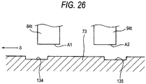
- Fig. 26 is a view showing the positional relationship among a detection surface A1 of the displacement sensor 84t, a detection surface A2 of the displacement sensor 94t, the first annular groove 134, and the second annular groove 135.
- the positional relationship among a detection surface of a displacement sensor 84b, a detection surface of a displacement sensor 94b, the first annular groove 134, and the second annular groove 135 is the same as the positional relationship among the detection surface A1 of the displacement sensor 84t, the detection surface A2 of the displacement sensor 94t, the first annular groove 134, and the second annular groove 135.
- the positional relationship among a detection surface of a displacement sensor 84f, a detection surface of a displacement sensor 94f, the first annular groove 134, and the second annular groove 135 is the same as the positional relationship among the detection surface A1 of the displacement sensor 84t, the detection surface A2 of the displacement sensor 94t, the first annular groove 134, and the second annular groove 135.
- the positional relationship among a detection surface of a displacement sensor 84r, a detection surface of a displacement sensor 94r, the first annular groove 134, and the second annular groove 135 is the same as the positional relationship among the detection surface A1 of the displacement sensor 84t, the detection surface A2 of the displacement sensor 94t, the first annular groove 1, and the second annular groove 135.
- a central portion of the detection surface A1 substantially coincides with the edge of the first annular groove 134 on the side of the second annular groove 135, and a central portion of the detection surface A2 substantially coincides with the edge of the second annular groove 135 on the side of the first annular groove 134.
- the displacement detection value of the second raceway member is amplified. This can enhance the detection sensitivity of the axial displacement of the sensor unit 10.
- the first annular groove on the inner side may be shifted to the outer side from the detection surface of the first displacement detector, and the second annular groove on the outer side may be shifted to the inner side from the detection surface of the second displacement detector. Even in this case, the same operational effects as the above ones can be obtained.
- the sensor unit 10 has a signal processing section 140, and the respective.displacement sensors 84t, 84b, 84f, 84r, 94t, 94b, 94f, and 94r are connected to the signal processing section 140 via signal lines 36 that pass through the lid member 53 of the case member 6.
- Output voltages (displacement detection values) obtained from the respective displacement sensors 84t, 84b, 84f, 84r, 94t, 94b, 94f, and 94r are calculated by an operation method in the signal processing section 140, and thereby, moment loads and translational loads in individual directions, which act on the wheel, are calculated.
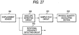
- Fig. 27 is a view showing, in the respective displacement sensors 84t, 84b, 84f, 84r, 94t, 94b, 94f and 94r, a method of extracting the displacement detection values from detection values of the respective displacement sensors, and a method of calculating the rotational speed of the inner shaft 1 from the detection values of the respective displacement sensors 84t, 84b, 84f, 84r, 94t, 94b, 94f and 94r.
- the displacement sensors 84b, 84f, 84r, 94t, 94b, 94f, and 94r also perform the same processing as the displacement sensor 84t.
- the description of the signal processing of the displacement sensors 84b, 84f, 84r, 94t, 94b, 94f and 94r is omitted by the description of the signal processing of the displacement sensor 84t.
- Fig. 28 is a view showing an example of detection values of the displacement sensor 84t.
- the detection values of displacement sensor 84t includes a rotation pulse signal resulting from irregularities that appear in the outer peripheral surface of the annular portion 150 due to the grooves 155 formed in the annular portion 150, and load signals related to the position of the first cylindrical surface portion 151, the position of the second cylindrical surface portion 152, and the positions of convexes of the outer peripheral surface of the annular portion 150, relative to the detection surface of the displacement sensor 84t.
- Fig. 27 detection values from the displacement sensor 84t are input to a well-known envelope detecting circuit 250 as an example of a displacement signal detector.
- Fig. 29 is a view showing output signals of the envelope detecting circuit 250.
- an envelope of detection values of the displacement sensor 84t is extracted by the envelope detecting circuit 250, and the information on the positions of the grooves 155 of the outer peripheral surface of the annular portion 150 in the information on the positions of the outer peripheral surface of the annular portion 150 are removed, while only the information on the positions of the convexes of the outer peripheral surface of the annular portion 150 is picked up.
- the load signals shown in Fig. 29 are displacement detection values used for calculation of the plurality of loads that are described above. In this way, displacement detection values are found by the respective displacement sensors 84t, 84b, 84f, 84r, 94t, 94b, 94f and 94r, and the values are processed in the gap detecting circuit shown in Fig. 25 . Thereafter, the signals processed in the gap detecting circuit are processed in a well-known sample hold circuit 251 (referto Fig. 27 ). Then, analog signals are properly converted into digital signals by a physical quantity calculating section 252 (refer to Fig. 27 ), and the respective loads Fx, Fy, Fz, Mx, and Mz are calculated in the process shown in Fig. 17 .
- the detection values from displacement sensor 84t are input to the rotational frequency detecting circuit 253 serving as a rotation signal detection section.
- the rotational frequency detecting circuit 253 compares, the detection values from the displacement sensor 84t with a predetermined value as a threshold value, and then converts the detection values from the displacement sensor 84t into pulse signals in which a high signal and a low signal are repeated.
- Fig. 29 is a view showing an example of output signals of the rotational frequency detecting circuit 253. High signals in the pulse signals are generated on the basis of detection of the grooves 155 of the annular portion 150, while low signals in the pulse signals are generated on the basis of detection of the convexes of the annular portion 150. On the basis of the period of the above pulse signals, the rotational speed of the annular portion 150, i.e., the inner shaft 1 is calculated.
- the gap detecting circuit, the sample hold circuit 251, and the physical quantity calculating section 252 constitute a moment load calculating section. Further, the gap detecting circuit, the envelope detecting circuit 250, the sample hold circuit 251, and the physical quantity calculating section 252 are included in the signal processing section 140.
- the first displacement detector 70 and the second displacement detector 71 that are spaced axially from each other are provided. Therefore, not only translational loads based on axial translational displacement can be calculated on the basis of a detection signal of the first displacement detector 70, and a detection signal of the second displacement detection signal 71, but also changes in displacement depending on the axial position of the rolling bearing device can be detected, and moment loads that act on the rolling bearing device can be calculated on the basis of the change in displacement.
- the displacement-detected portion that is an outer peripheral surface of the target member 73 has an annular portion 150 having a plurality of grooves 155 that are arranged at intervals from each other in a circumferential direction of the displacement-detected portion and extend axially
- the sensor unit 10 has a rotational frequency detector 253 that detects a signal associated with the relative rotation of the annular portion 150 on the basis of an output of at least one of the first displacement detector 70 and the second displacement detector 71, and an envelope detecting circuit 250 that detects a signal associated with the displacement of the displacement-detected portion from an output of the first displacement detector 70, and detects a signal associated with the displacement of the displacement-detected portion from an output of the second displacement detector 71.
- the rolling bearing device can be made compact, and the manufacturing cost of the rolling bearing device can be suppressed.
- the axial translational displacement of the rolling bearing device can be easily and simply detected, and the axial translational loads thereof can be easily detected, by detecting the axial position of the stepped portion 156 between the annular portion 150 and the first cylindrical surface portion 151, and the axial position of the stepped portion 157 between the annular portion 150 and the second cylindrical surface portion 152.
- the surface of the annular portion 150 has a structure in which magnetic properties are good, passage of magnetic fluxes is easy, and an eddy current is hardly generated, i.e., a structure in which a plurality of silicon steel plates 200 (although silicon steel plates are used in the above embodiment, any kind of steel places may be used) are axially stacked, the loss of an electric signal resulting from the generation of an eddy current can be reduced, and the sensitivity of the sensors can be made high.
- the annular portion 150 can be easily grooved. Further, since C ⁇ A+ B is satisfied, the resolution of pulse signals can be made high. Further, since B ⁇ C is satisfied, the rotational speed for short time can be calculated.
- the displacement-detected portion is the outer peripheral surface of the target member 73 that is separate from the inner shaft 1.
- the displacement-detected portion may be a portion of an outer peripheral surface of the inner shaft, not the target member.
- the inner ring 2 that is separate from the inner shaft 1 is adapted to fit to the inner shaft 1.
- the second raceway member may be constituted by only the inner shaft, not the inner ring, or may be constituted by the inner shaft and the target member, and the inner shaft may have two raceway surfaces on the outer peripheral surface of the inner shaft.
- a ⁇ B, C ⁇ A + B, and B ⁇ C are satisfied.
- a ⁇ B may be satisfied
- C ⁇ A + B may be satisfied
- B ⁇ C may be satisfied.
- the sensor unit that can be used in the invention is not limited to the sensor unit 10 used in the above embodiment, and may be sensor units whose portions are shown in Figs. 31, 32, and 33 .
- the annular grooves 134 and 135 may not be formed in the target member 473, but annular striped portion 434 and 435 that have larger (or smaller) permeability than its surrounding constituent material may be formed in positions where the annular grooves 134 and 135 existed.
- the annular striped portion 434 and 435 can be formed by changing carbon content in the case of, for example, steel.
- convex portions 541 and 542 whose outer peripheral surfaces are cylinder surfaces may be formed in the positions of the target member 573 where the annular grooves 134 and 135 were formed in the above embodiment, and an annular portion 550 the outer diameter of a convex portion of which is smaller than the convex portions 541 and 542 may be formed in the position where the annular portion 150 was formed.
- inclined portions 643 and 644 the directions of inclination of which are opposite to each other in an axial section may be formed on an outer peripheral surface of a target member 673, and an annular portion having a groove may be formed in a portion of each of the inclined portions 643 and 644.
- Fig. 33 shows that joined portions of both the inclined portions 643 and 644 are formed in the shape of a valley, the joined portions may be formed as both inclined portions that are formed in the shape of a chevron.
- the sensor unit that can be used in the invention is not limited to the inductance-type displacement sensor that has been described in the embodiment. That is, the sensor unit that can be used in the invention may be any kinds of displacement sensors as long as they are non-contact-type sensor units that can detect a gap.
- the rolling bearing device is a hub unit.
- the rolling bearing devices with a sensor of this invention is not limited.the hub unit, and may be any kinds of bearing devices, such as a magnetic bearing device, other than the hub unit. This is because it is needless to say that the configuration of the invention described in the embodiment can be applied to various bearing devices with the needs for measuring a plurality of moment loads or translational loads.
- the rolling elements of a rolling bearing with a sensor to be manufactured are balls.
- the rolling elements of the rolling bearing with a sensor to be manufactured may be rollers or may include rollers and balls.
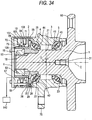
- Fig. 34 is an axial sectional view of a hub unit of a rolling bearing device according to a third embodiment the invention.
- An outer peripheral surface of the inner ring 2 has a cylindrical outer peripheral surface 26 at the opposite side of large-diameter shaft portion 21 in the axial direction.
- the cylindrical outer peripheral surface 26 communicates through a step portion 30 to a raceway shoulder portion 29 located at the opposite side of the large-diameter shaft portion 21 of the raceway groove 28.
- the raceway shoulder portion 29 has a cylindrical outer peripheral surface 35.
- An outer diameter of the cylindrical outer surface 26 located at the axial end of the outer peripheral surface of the inner ring 2 is smaller than an.outer diameter of the cylindrical outer surface 35 of the raceway shoulder portion 29.
- the inner shaft 1, the inner ring 2, and the magnet fixing member 109 constitute a second raceway member.
- the tubular magnet 73 is externally fitted and fixed to an outer peripheral surface of the magnet fixing member 109.
- Fig. 35 is an enlarged sectional view around the displacement detectors 70 and 71 in Fig. 34 .
- the second displacement detector 71 is located closer to a wheel (a wheel-attaching flange 50) than the first displacement detector 70.
- the first displacement detector 70 is the same as the second displacement detector 71, and the first displacement detector 70 is arranged at a distance axially from the second displacement detector 71.
- the whole first displacement detector 70 overlaps the second displacement detector 71 substantially axially.
- the first displacement detector 70 is composed of four hall elements (hereinafter referred to as "first hall elements") 84, while the second displacement detector 71 has four hall elements (hereinafter referred to as “second hall elements”) 94.
- the first displacement detector 70 and second displacement detector 71 can be fixed to the case member 6 via the columnar first fixing portion 107 and the second columnar fixing portion 108. Accordingly, only by fixing the case member 6 to the outer peripheral surface of the outer ring 3 as described above after the first displacement detector 70 and the second displacement detector 71 are fixed to the case member 6, the first and second displacement detectors 70 and 71 can be simply fixed to the hub unit. That is, it is not necessary to individually attach the displacement detectors 70 and 71 to the outer ring 3, and it is also not necessary to provide the outer ring 3 with an attachment structure, such as through-holes, for mounting the displacement detectors 70 and 71. Further, since the positions of the displacement detectors 70 and 71 relative to the case member 6 are determined in advance, the displacement detectors 70 and 71 with respect to the magnet 73 can be exactly and easily positioned.
- Fig. 36 is a view showing the relationship of a relative position between the first displacement detector 70 and the second displacement detector 71, and the magnet 73.
- the magnet 73 is a so-called a pulser ring. N poles and S poles are alternately located in a circumferential direction on the outer peripheral surface of the magnet 73, while S poles and N poles are alternately located in the circumferential direction on the inner peripheral surface of the magnet 73, As shown in Fig. 36 , an N-pole portion of the outer peripheral surface of the magnet 73 radially faces an S-pole portion of the inner peripheral surface of the magnet 73, and an S-pole portion of the outer peripheral surface of the magnet 73 radially faces an N-pole portion of the inner peripheral surface of the magnet 73.
- each of the first hall elements 84 radially faces one axial end surface of the magnet 73 at a distance therefrom, while an axial central portion in the radial inner end surface of each of the second hall elements 94 radially faces the other axial end surface of the magnet 73 at a distance therefrom.
- Fig. 37 is a radial sectional view passing through the magnet 73 and the first hall elements 84, and is a view for explaining a circumferential arrangement configuration of the first hall elements 84.
- the second hall elements 94 also have the same circumferential arrangement structure as the first hall elements 84. The description of the structure and suffixes of the second hall elements 94 is omitted by the description of the structure and suffixes of the first hall elements 84.
- the four first hall elements 84 are arranged at equal intervals in the circumferential direction of the inner shaft 1. Specifically, the first hall elements 84 are installed in a position that radially faces the portion of the magnet 73 that is located on the vertical topmost side, a position that radially faces the portion of the magnet 73 that is located on the vertical bottommost side, a position that radially faces the foremost position of a vehicle to which the hub unit is attached in the magnet 73, and a position that radially faces the rearmost position of the vehicle to which the hub unit is attached in the magnet 73, in a state where the hub unit is installed in a predetermined position.
- a first hall element 84 installed in a position that radially faces the portion of the magnet 73 that is located on the vertical topmost side is defined as a first hall element 84t
- a first hall element 84 installed in a position that radially faces the portion of the magnet 73 that is located on the vertical bottommost side is defined as a first hall element 84b
- a first hall element 84 installed in a position that radially faces the foremost position of a vehicle to which the hub unit is attached in the magnet 73 is defined as a first hall element 84f
- a first hall element 84 installed in a position that substantially radially faces the rearmost position of the vehicle to which the hub unit is attached in the magnet 73 is defined as a first hall element 84r.
- the first displacement detector 70 and the second displacement detector 71 have eight hall-elements in total, i.e., the first hall elements 84t, 84b, 84f, and 84r, and the second hall elements 94t, 94b, 94f, and 94r.
- the eight hall elements 84t, 84b, 84f, 84r, 94t, 94b, 94f, and 94r are the same.
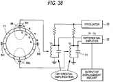
- Fig. 38 is a view showing an example of a gap detecting circuit connected to the first displacement detector 70.
- the same gap detecting circuit as one connected to the first displacement detector 70 is also connected to the second displacement detector 71.
- the two first hall elements 84t and 84b that are located in the vertical direction are connected to an oscillator 130.
- An alternating current during.a fixed period is supplied to the first hall elements 84tand 84b from the oscillator 130.
- a synchronizing capacitor 131 is connected in parallel to the first hall elements 84t and 84b.
- a differential amplifier 132 the values of envelopes of output voltages of the first hall elements 84t and the first hall elements 84b (hereinafter, in each hall element, the values of an envelope of output voltages of the hall element, which will be explained below in detail, are called displacement detection values), and taking them as output voltages (displacement detection values) corresponding to the vertical direction, noises of a temperature drift are eliminated, and the sensitivity of a displacement signal in the vertical direction is improved about twice by differential amplification.
- the radial gap from the hall elements 84t, 84b, 84f, 84r, 94t, 94b, 94f, and 94r to the magnet 73, and the radial overlap between the hall elements 84t, 84b, 84f, 84r, 94t, 94b, 94f and 94r, and the magnet change the magnitudes of the magnetic forces detected by the hall elements 84t, 84b, 84f, 84r, 94t, 94b, 94f, and 94r change, and output voltages from the hall elements 84t, 84b, 84f, 84r, 94t, 94b, 94f, and 94r change.
- the axial positions of the magnet 73 with respect to the first and second hall elements 84t and 94t are set so that the displacement detection values to be detected by the first hall element 84t and the second hall element 94t may be changed in positive/negative opposite directions.
- the axial translational amount (this is an axial displacement, and has a correlation with a translational load) of the inner ring 2 (inner shaft 1) is detected.
- the operation method for calculating the displacement detection values is substantially identical to the operation method according to the first embodiment. Therefore, the description thereof is omitted.
- the first hall elements 84t, 84b, 84f, and 84r correspond to the displacement sensor 84t, 84b, 84f, and 84r in the first embodiment
- the second:hall element 94t, 94b, 94f, and 94r correspond to the displacement sensor 94t, 94b, 94f, and 94r in the first embodiment.
- Fig. 40 is a view showing an example of detection values of the first hall element 84t.
- the detection values of the first hall element 84t include a rotation pulse signal resulting from N poles and S poles alternately magnetized in the circumferential direction by the magnet 73, and a load signal related to the position of the magnet 73 to the first hall element 84t.
- detection values from the first hall element 84t are input to a well-known envelope detecting circuit 250 serving as an example of a displacement signal detector.
- An envelope of detection values of the first hall element 84t is extracted by the envelope detecting circuit 250, and only a load signal related to the position of the magnet 73 to the first hall element 84t is picked up.
- the detection values from the first hall element 84t are input to a rotational frequency detecting circuit 253 serving as a rotation signal detection section.
- the rotational frequency detecting circuit 253 compares, the detection values from the first hall element 84t with a predetermined value as a threshold value, and then converts the detection values from the first hall element 84t into pulse signals in which a high signal and a low signal are repeated.
- the rotational speed of an annular portion 150 i.e., the inner shaft 1 is calculated.
- the gap detecting circuit, the sample hold circuit 251, and the physical quantity calculating section 252 constitute a moment load calculating section. Further, the gap detecting circuit, the envelope detecting circuit 250, the sample hold circuit 251, and the physical quantity calculating section 252 are included in the signal processing section 140.
- the first displacement detector 70 and the second displacement detector 71 that are spaced axially from each other are provided. Therefore, not only translational loads based on.axial translational displacement can be calculated on the basis of a detection signal of the first displacement detector 70, and a detection signal of the second displacement detection signal 71, but also changes in displacement depending on the axial position of the rolling bearing device can be detected, and moment loads that act on the rolling bearing device can be calculated on the basis of the change in displacement.
- the cylindrical magnet 73 is externally fitted to an outer peripheral surface of the magnet fixing member 109 that forms a portion of the second raceway member, N poles and S poles are alternately located in a circumferential direction on an outer peripheral surface of the magnet 73, while S poles and N poles are alternately located in the circumferential direction on an inner peripheral surface of the magnet 73, and when the magnet 73 is relatively rotated, the first hall elements 84t, 84b, 84f, and 84r and the second hall elements 94t, 94b, 94f and 94r are arranged in positions where magnetic information generated by the N poles and the S poles can be read.
- the first displacement detector 70 and the second displacement detector 71 are the same, the whole first displacement detector 70 overlaps the second displacement detector 71 substantially axially, and the first displacement detector 70 has four same hall elements 84t, 84b, 84f, and 84r that are disposed at equal intervals in the circumferential direction. Therefore, changes in displacement depending on the axial position of the rolling bearing device can be easily and precisely detected. Accordingly, moment loads can be precisely detected.
- moment loads that act on a wheel can be calculated in the moment load calculating section. Accordingly, the rotational speed of the wheel, and the moment loads that act on the wheel can be calculated, and operation control during traveling of a vehicle can be precisely performed on the basis of such information.
- the moment load calculating section calculates, in each of the first hall elements. 84t, 84b, 84f, and 84r, differences between signals associated with the displacement of the magnet 73, of the first hall elements 84t, 84b, 84f, and 84r and signals associated with the displacement of the magnet 73, of the second hall elements 94t, 94b, 94f, and 94r that overlap the first hall elements 84t, 84b, 84f, and 84r substantially axially, and then calculates moment loads that act on a wheel on the basis of the differences. Therefore, the sensitivity of detection of displacement in a detection direction can be approximately doubled, and the noise of a temperature drift in the detection direction can be removed.
- the tubular magnet 73 is fixed to the outer peripheral surface of the magnet fixing member 109 fixed to the inner ring 2.
- the tubular magnet may be fixed to the outer peripheral surface of the inner shaft, and the outer peripheral surface of the inner ring.
- the inner ring 2 that is separate from the inner shaft 1 is adapted to fit to the inner shaft 1.
- the second raceway member may be constituted by only the inner shaft, not the inner ring, or the inner shaft may have two raceway surfaces on the outer peripheral surface of the inner shaft.
- the outer ring 3 constitutes a fixed raceway ring
- the inner shaft 2 and the like on the inner circumferential side constitutes a rotating raceway ring
- the inner shaft and the like on the inner circumferential side may constitute the fixed raceway ring
- the outer ring may constitute the rotating raceway ring.
- the rolling elements of a rolling bearing with a sensor to be manufactured are balls.
- the rolling elements of the rolling bearing with a sensor to be manufactured may be rollers or may include rollers and balls.
- Fig. 41 is an axial sectional view of a rolling bearing device manufactured by a manufacturing method of a rolling bearing device according to a fourth embodiment of the invention.
- This rolling bearing device is a hub unit
- This rolling bearing device includes an inner shaft 1, an inner ring 2, an outer ring 3, a plurality of first balls 4 serving as first rolling elements, a plurality of second balls 5 serving as second rolling elements, a case member 6, a shielding plate 7 serving as a sealing unit, and a displacement sensor unit 10.
- the inner shaft 1 has a first center hole 30 and a second center hole 31.
- the first center hole 30 is formed in an axial central portion of an axial end surface of the inner shaft 1 on the side of the small-diameter shaft portion 19, while the second center hole 31 is formed in an axial central portion of an axial end surface of the inner shaft 1 on the side of the large-diameter shaft portion 21.
- the first center hole 30 has a substantially semi-spherical shape, while the second center hole 31 has a cylindrical portion, and extends by a predetermined distance axially.
- the inner shaft 1 has a wheel-attaching flange 50 for attaching a wheel (not shown) to an axial end thereof on the side of the large-diameter shaft portion 21.
- the inner ring 2 is externally fitted and fixed to an outer peripheral surface of the middle-diameter shaft portion 20 of the inner shaft 1.
- An axial end surface of the inner ring 2 on the side of the large-diameter shaft portion 21 abuts on the stepped portion 22.
- the inner ring 2 has an angular raceway groove 28 serving as an outer circumferential raceway surface in its outer peripheral surface on the side of the large-diameter.shaft portion 21.
- the outer diameter of the raceway groove 28 becomes large as being separated from the large-diameter shaft portion 22.
- An axial portion of an outer peripheral surface of the inner ring 2 opposite the large-diameter shaft portion 21 has a cylindrical outer peripheral surface 26, and the cylindrical outer peripheral surface 26 is connected to a raceway shoulder 29 of the raceway groove 28, which is located opposite the large-diameter shaft portion 21, via a stepped portion 30.
- the raceway shoulder 29 has a cylindrical outer peripheral surface. The outer diameter of the cylindrical outer peripheral surface 26 is smaller than the outer diameter of the cylindrical outer peripheral surface of the raceway shoulder 29.
- the shielding plate 7 seals a gap between an axial end of an inner peripheral surface of the outer ring 3 on the side of the first raceway groove 44, and the cylindrical outer peripheral surface of the raceway shoulder 29 of the inner ring 2 by a labyrinth seal.
- the shielding plate 7 has a substantially L-shaped section, and has an axially extending portion and a radially extending portion.
- the axially extending portion has a tubular shape and extends axially.
- the radially extending portion extends radially inward from one end of the axially extending portion.
- a cylindrical outer peripheral surface of the axially extending portion is internally fitted and fixed to an end of an inner peripheral surface of the outer ring 3 on the side of the small-diameter shaft portion 19. Meanwhile, the radially extending portion radially faces the cylindrical outer peripheral surface of the raceway shoulder 29 via a slight gap.
- Fig. 42 is an enlarged sectional view around the displacement sensor unit 10 in Fig. 41 .
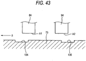
- Fig. 43 is a view showing the positional relationship among a detection surface A1 of the displacement sensor 84, a detection surface A2 of the displacement sensor 94, the first annular groove 134, and the second annular groove 135.
- the displacement sensor unit 10 is configured such that the displacement sensor 84 and the displacement sensor 94 are arranged adjacent to each other axially, in an axial section, the inclination of the target member 73 with respect to the detection surfaces A1 and A2 can be detected in 4 sets of two displacement sensors 84 and 94 that substantially axially overlap each other.
- the displacement sensor unit 10 is adapted to calculate a translational load in an up-and-down direction of a wheel, a translational load in an axial direction of the wheel, and a translational load in a front-back direction of the wheel, but also to detect moment loads (specifically, a moment load around the up-and-down direction of the wheel and a moment load around the front-back direction of the wheel) that act on the rolling bearing device on the basis of the inclination.
- a central portion of the detection surface A1 on the lid member 53 substantially coincides with the edge of the first annular groove 134 on the side of the second annular groove 135, and a central portion of the detection surface A2 substantially coincides with the edge of the second annular groove 135 on the side of the first annular groove 134.
- the detection surface A1 of the displacement sensor on the side of the lid member axially overlaps a portion of the first annular groove on the side of the lid member
- a portion of the detection surface A2 of the displacement sensor on the side of the rolling elements axially overlaps a portion of the second annular groove on the side of the rolling elements, the same operational effects as the fourth embodiment can be obtained.
- the inner ring 2 is externally fitted and fixed to the middle-diameter shaft portion 20 of the inner shaft 1.
- the first balls 4, the second balls 5, and the outer ring 5 are assembled to an inner shaft assembly in which the inner ring 2 is externally fitted to the inner shaft 1.
- the nut 63 is screwed to the thread of the small-diameter shaft portion 19 of the inner shaft 1 whereby the inner ring 2 is screwed to the axial large-diameter shaft portion 21 with the nut 63, thereby setting a preload between the raceway groove 28 of the inner ring 2 and the first raceway groove 44 of the outer ring 3 to a predetermined preload, and setting a preload between the raceway groove 23 of the inner shaft 1 and the second raceway groove 45 of the outer ring to a predetermined preload.
- the one end of the target member 73 is externally fitted and fixed to the cylindrical outer peripheral surface 26 of the inner ring 2 by pressing fitting.
- the shielding plate denoted by 7 in Fig. 41 is internally fitted and fixed to the axial end of the inner peripheral surface of the outer ring 3 on the side of the small-diameter shaft portion 19 by press fitting, thereby forming a labyrinth seal between the axial end of the inner peripheral surface of the outer ring 3 on the side of the small-diameter shaft portion 19 and the cylindrical outer peripheral surface of the raceway shoulder 29 of the inner ring 2.
- the wheel-attaching flange 50 of the inner shaft 1 is held with a chuck device that is not shown whereby a torque is given to the inner shaft 1 using the chuck device, thereby rotating the inner shaft 1 around the central axis of the second center hole 31 on the basis of the central axis of the second center hole 31.
- the outer peripheral surface of the target member 73 is cut in the state where the inner shaft 1 is rotating around the central axis, thereby roughly forming the first annular groove 134 and the second annular portion 135 in the outer peripheral surface of the target member 73, and thereafter, the outer peripheral surface of the target member 73 is precisely polished in a predetermined shape.
- the tubular member 52 of the case member 6 with which the sensor body 60 becomes integral is fixed to the outer peripheral surface of the outer ring 3 with locking screws 55 (refer to Fig. 41 ), thereby forming a rolling bearing device.
- the manufacturing method of the rolling bearing device with the sensor of the fourth embodiment after axial one end of the inner peripheral surface of the tubular target member 73 is press-fitted to the cylindrical outer peripheral surface 26 that is one end of the outer peripheral surface of the inner ring 2, the outer peripheral.surface of the target member 73 is processed. Therefore, the press-fitting of the target member 73 to the inner ring 2 does not affect the dimensions of the target member 73 of the rolling bearing device after manufacture, so that the outer peripheral surface of the target member 73 can be precisely positioned in a predetermined position.
- the target member 73 is processed in a distorted state. Therefore, any degradation of positioning precision of the outer peripheral surface resulting from the distortion caused by the press fitting, which is conventionally generated in a case where press-fitting is performed after processing, does not occur. Further, in a case where press-fitting is performed after processing, the degradation of positioning precision of the outer peripheral surface of the target member degrades due to the precision of the position of the outer peripheral surface of the target member. In the invention, however, the target member is processed after press-fitting of the target member. Therefore, any degradation of positioning precision of the outer peripheral surface of the target member resulting from the precision of the position of the outer peripheral surface of the inner ring does not occur.
- the outer peripheral surface of the target member 73 that is press-fitted to the cylindrical outer peripheral surface 26 that is one end of the outer peripheral surface of the inner ring 2 is processed in a state where the inner shaft 1 is rotated around about the central axis of the inner shaft 1. Therefore, in comparison with a case where the outer peripheral surface of the target member is processed without rotating the inner shaft, any runout of the rolling bearing device can be efficiently removed during the processing of the outer peripheral surface of the target member 73, and accordingly, the rotation variation of the rolling bearing device after manufacture can be suppressed.
- the outer peripheral surface of the target member 73 is processed after a gap between the outer ring 3 and the inner ring 2 is sealed by the shielding plate 7. Therefore, abrasion powder of the target member 73 generated by processing (including polishing) does not reach the first and second balls 3 and 4, or the raceway grooves 23 and 28, 44, and 45, and accordingly, the first and second balls 3 and 4 or the raceway grooves 23, 28, 44, and 45 can be surely protected from the abrasion powder.
- the inner shaft 1 is rotated on the basis of the second center hole 31 that extends axially and has an axial length. Therefore, it becomes easy to make a rotation centerline to be used as the reference of the rotation of the inner shaft 1 more precisely coincide with the central axis of the inner shaft 1. Accordingly, runout (decentering) of the rolling bearing device can be further suppressed.
- the sensor body 60 can be fixed to the rolling bearing device only by fixing the case member 6 to the outer peripheral surface of the outer ring 1 as described above. Accordingly, it is not necessary to individually attach the sensor body 60 to the outer ring 3, and it is also not necessary to provide the outer ring 3 with an attachment structure, such as through-holes, for mounting the sensors. Further, since the position of the sensor body 60 relative to the case member 6 is determined in advance, the sensor body 60 with respect to the target member 73 can be exactly and easily positioned.
- an axial end on the side of the target member 73 between the inner ring 2 and the outer ring 3 is sealed by the shielding plate 6 after the target member 73 is press-fitted to the inner ring 2.
- the target member 73 is press-fitted to the outer peripheral surface of the inner ring 2 after the axial opening on the side of the target member 73 between the inner ring 2 and the outer ring 3 is sealed by a sealing unit.
- centering of the inner shaft 1 when the inner shaft 1 is rotated is made using the second center hole 31 of the inner shaft 2.
- the centering of the inner shaft when the inner shaft is rotated may be made on the basis of the portion of the inner shaft, such as an axial end surface of the inner shaft, other than the second center hole of the inner shaft.
- the rolling elements of a rolling bearing with a sensor to be manufactured are balls.
- the rolling elements of the rolling bearing with a sensor to be manufactured may be rollers or may include rollers and balls.
Landscapes
- Engineering & Computer Science (AREA)
- General Engineering & Computer Science (AREA)
- Chemical & Material Sciences (AREA)
- Analytical Chemistry (AREA)
- Mechanical Engineering (AREA)
- Physics & Mathematics (AREA)
- General Physics & Mathematics (AREA)
- Rolling Contact Bearings (AREA)
Claims (9)
- Dispositif de roulement à rouleaux avec un capteur comprenant :- un premier élément de chemin de roulement (3) comprenant une surface périphérique intérieure ayant une surface de chemin de roulement (44, 45) ;- un second élément de chemin de roulement comprenant une surface périphérique extérieure ayant une surface de chemin de roulement (23) ;- une partie de détection de déplacement annulaire (73) prévue séparément du second élément de chemin de roulement et disposée sur la surface périphérique extérieure du second élément de chemin de roulement ;- des éléments de roulement (4, 5) agencés entre les surfaces de chemins de roulement du premier et du second éléments de chemins de roulement ; et- une unité de capteur (10) qui détecte le déplacement radial et le déplacement axial de la partie de détection de déplacement (73),- dans lequel l'unité de capteur (10) comprend :caractérisé en ce que- un premier détecteur de déplacement (70) ayant une surface de détection tournée radialement vers la partie de détection de déplacement (73) ;- un second détecteur de déplacement (71) situé axialement à une distance du premier détecteur de déplacement (70), et ayant une surface de détection tournée radialement vers la partie de détection de déplacement (73) ;- un détecteur de signal de rotation qui détecte un signal associé à la rotation de la partie annulaire (150) par rapport à au moins l'un du premier détecteur de déplacement (70) et du second détecteur de déplacement (71), sur la base d'une sortie d'au moins l'un du premier détecteur de déplacement et du second détecteur de déplacement, et- un détecteur de signal de déplacement qui détecte un signal associé au déplacement de la partie de détection de déplacement (73) sur la base d'une sortie du premier détecteur de déplacement (70), et détecte un signal associé au déplacement de la partie de détection de déplacement (73) sur la base d'une sortie du second détecteur de déplacement (71), dans lequel la partie de détection de déplacement (73) est reliée à une partie annulaire (150) ayant une pluralité de rainures (134, 135) qui sont agencées à des intervalles les unes des autres dans une direction circonférentielle de la partie de détection de déplacement (73) et s'étendent axialement,- la partie de détection de déplacement (73) comprend une première partie de surface cylindrique reliée à la partie annulaire par le biais d'une partie échelonnée, et une seconde partie de surface cylindrique reliée à la partie annulaire opposée à la première partie de surface cylindrique par le biais d'une partie échelonnée (156), et située sensiblement sur la même surface cylindrique que la première partie de surface cylindrique (151),- chacune des rainures (134, 135) s'étend axialement entre une extrémité axiale de la partie annulaire (150) et l'autre extrémité axiale de la partie annulaire,- le premier détecteur de déplacement (70) et le second détecteur de déplacement (71) se chevauchent de manière sensiblement axiale,- la surface de détection du premier détecteur de déplacement (70) chevauche radialement une extrémité de la première partie de surface cylindrique (151) sur le côté de la partie annulaire (150), et chevauche radialement une extrémité de la partie annulaire (150) sur le côté de la première partie de surface cylindrique, et- la surface de détection du second détecteur de déplacement (71) chevauche radialement une extrémité de la seconde partie de surface cylindrique (152) sur le côté de la partie annulaire (150), et chevauche radialement une extrémité de la partie annulaire (150) sur le côté de la seconde partie de surface cylindrique (152).
- Dispositif de roulement à rouleaux selon la revendication 1, dans lequel une surface de la partie annulaire est formée en empilant axialement une pluralité de plaques d'acier.
- Dispositif de roulement à rouleaux selon la revendication 1, dans lequel- la pluralité de rainures (134, 135) possèdent sensiblement la même largeur, et sont agencées à des intervalles identiques dans la direction circonférentielle,- le premier détecteur de déplacement (70) et le second détecteur de déplacement (71) se chevauchent de manière sensiblement axiale,- chacun du premier détecteur de déplacement (70) et du second détecteur de déplacement (71) comprend quatre capteurs de déplacement agencés à des intervalles identiques dans la direction circonférentielle, et- A < B, C < A + B, et B < C sont satisfaits- où, sur une vue radiale en coupe qui passe par la partie annulaire et le premier détecteur de déplacement (70), lorsque les deux rainures adjacentes dans la direction circonférentielle sont définies comme une première rainure et une seconde rainure, une courbure située entre la première rainure et la seconde rainure est définie comme une courbure intermédiaire, une ligne droite passant par un point intermédiaire circonférentiel de la courbure intermédiaire et un centre de la partie annulaire est définie comme une ligne passant par le centre de la courbure, une distance entre une ligne droite parallèle à la ligne passant par le centre de la courbure et passant par une extrémité circonférentielle de la première rainure, et une ligne droite parallèle à la ligne passant par le centre de la courbure et passant par l'autre extrémité circonférentielle de la première rainure est représentée par A, une distance entre une ligne droite parallèle à la ligne passant par le centre de la courbure et passant par une extrémité circonférentielle de la courbure intermédiaire, et une ligne droite parallèle au centre de la courbure et passant par l'autre extrémité circonférentielle de la courbure intermédiaire est représentée par B, et un quart d'une longueur circonférentielle de la surface de détection du premier détecteur de déplacement (70) est représenté par C.
- Dispositif de roulement à rouleaux selon la revendication 1, dans lequel- le second élément de chemin de roulement (1) comprend une bride de fixation de rotor (50) destinée à fixer un rotor, et le premier élément de chemin de roulement (3) comprend une bride de fixation de châssis destinée à fixer un châssis de véhicule,- la pluralité de rainures sont agencées à des intervalles identiques dans la direction circonférentielle,- le premier détecteur de déplacement (70) et le second détecteur de déplacement (71) se chevauchent de manière sensiblement axiale,- chacun du premier détecteur de déplacement (70) et du second détecteur de déplacement (71) comprend quatre capteurs de déplacement agencés à des intervalles identiques dans la direction circonférentielle ;- le détecteur de signal de déplacement détecte, dans chacun des capteurs de déplacement, les signaux associés au déplacement de la partie de détection de déplacement sur la base des signaux délivrés par chacun des capteurs de déplacement,- les capteurs de déplacement du second détecteur de déplacement (71) chevauchent de manière sensiblement axiale les capteurs de déplacement du premier détecteur de déplacement (70), et- l'unité de capteur possède une section de calcul de charge momentanée qui reçoit des signaux de la part du détecteur de signal de déplacement, calcule, dans chacun des capteurs de déplacement du premier détecteur de déplacement, les différences entre les signaux associés au déplacement de la partie de détection de déplacement par rapport aux capteurs de déplacement du premier détecteur de déplacement et les signaux associés au déplacement de la partie de détection de déplacement par rapport aux capteurs de déplacement du second détecteur de déplacement, et calcule une pluralité de charges momentanées qui agissent sur le dispositif de roulement à rouleaux sur la base des différences calculées.
- Dispositif de roulement à rouleaux selon la revendication 1, dans lequel- la partie de détection de déplacement (73) comprend un aimant cylindrique placé de manière externe sur la surface périphérique extérieure du second élément de chemin de roulement ;- l'unité de capteur (10) comprend :- un premier détecteur de déplacement (70) ayant un premier élément de Hall ou une pluralité de premiers éléments de Hall dont les positions d'existence axiales sont sensiblement les mêmes ; et- un second détecteur de déplacement (71) ayant un second élément de Hall ou une pluralité de seconds éléments de Hall dont les positions d'existence axiales sont sensiblement les mêmes, et situé axialement à une distance du premier détecteur de déplacement ;- les pôles N et les pôles S sont situés de manière alternée dans une direction circonférentielle de l'aimant sur une surface périphérique extérieure de l'aimant, tandis que les pôles S et les pôles N sont situés de manière alternée dans la direction circonférentielle sur une surface périphérique intérieure de l'aimant de sorte que les pôles N de la surface périphérique extérieure de l'aimant soit tournés vers les pôles S de la surface périphérique intérieure de l'aimant dans une direction radiale de l'aimant, et que les pôles S de la surface périphérique extérieure de l'aimant soient tournés vers les pôles N de la surface périphérique intérieure de l'aimant dans la direction radiale de l'aimant, et- au moins une partie du premier élément de Hall est tournée radialement vers une extrémité axiale de l'aimant, et au moins une partie du second élément de Hall est tournée radialement vers l'autre extrémité axiale de l'aimant.
- Dispositif de roulement à rouleaux selon la revendication 5, dans lequel- le premier détecteur de déplacement (70) et le second détecteur de déplacement (71) se chevauchent de manière sensiblement axiale,- le premier détecteur de déplacement (70) comprend les quatre premiers éléments de Hall, et le second détecteur de déplacement (71) comprend les quatre seconds éléments de Hall, et- les quatre premiers éléments de Hall sont agencés à des intervalles réguliers dans la direction circonférentielle.
- Dispositif de roulement à rouleaux selon la revendication 6, dans lequel- le second élément de chemin de roulement comprend une bride de fixation de rotor (50) destinée à fixer un rotor, et le premier élément de chemin de roulement (3) comprend une bride de fixation de châssis destinée à fixer un châssis de véhicule,- le détecteur de signal de déplacement détecte, dans chacun des quatre premiers éléments de Hall et des quatre seconds éléments de Hall, les signaux associés au déplacement de l'aimant sur la base des signaux délivrés par les premiers ou les seconds éléments de Hall, et- l'unité de capteur (10) possède une section de calcul de charge momentanée qui reçoit des signaux de la part des détecteurs de signaux de déplacement, calcule, dans chacun des premiers éléments de Hall, les différences entre les signaux associés au déplacement de l'aimant par rapport aux premiers éléments de Hall et les signaux associés au déplacement de l'aimant par rapport aux seconds éléments de Hall, et calcule les charges momentanées qui agissent sur le dispositif de roulement à rouleaux sur la base des différences calculées.
- Dispositif de roulement à rouleaux selon la revendication 1, dans lequel- le second élément de chemin de roulement comprend un arbre intérieur,- un premier élément tubulaire (52) est vissé sur une extrémité axiale d'une surface périphérique extérieure de l'arbre intérieur ;- un second élément tubulaire (191) est fixé sur une surface périphérique extérieure du premier élément tubulaire (52) et formé en empilant axialement une pluralité de plaques d'acier au silicium ; et- une paire de troisièmes éléments tubulaires est fixée sur la surface périphérique extérieure du premier élément tubulaire (52), est située sur les côtés opposés du second élément tubulaire (191), et est composée d'un matériau non magnétique,- la partie de détection de déplacement est constituée d'une surface périphérique extérieure du second élément tubulaire (191) et des surfaces périphériques extérieures de la paire de troisièmes éléments tubulaires,- une extrémité ouverte d'une surface périphérique intérieure du premier élément tubulaire (52) est munie d'un orifice d'engagement,- un diamètre extérieur de la surface périphérique extérieure du second élément tubulaire (191) est supérieur à un diamètre extérieur de la paire de troisièmes éléments tubulaires.
- Dispositif de roulement à rouleaux selon la revendication 8, dans lequel- le second élément tubulaire (191) bute axialement contre la paire de troisièmes éléments tubulaires sur les côtés opposés du second élément tubulaire,- un diamètre extérieur des surfaces périphériques extérieures de la paire de troisièmes éléments tubulaires est sensiblement constant,- le premier détecteur de déplacement (70) et le second détecteur de déplacement (71) se chevauchent de manière sensiblement axiale,- la surface de détection du premier détecteur de déplacement (70) chevauche radialement une extrémité axiale du second élément tubulaire sur le côté de l'un des troisièmes éléments tubulaires, et chevauche radialement une extrémité axiale de l'un des troisièmes éléments tubulaires sur le côté du second élément tubulaire, et- la surface de détection du second détecteur de déplacement (71) chevauche radialement l'autre extrémité axiale du second élément tubulaire sur le côté de l'autre troisième élément tubulaire, et chevauche radialement l'autre extrémité axiale de l'autre troisième élément tubulaire sur le côté du second élément tubulaire (191).
Applications Claiming Priority (4)
| Application Number | Priority Date | Filing Date | Title |
|---|---|---|---|
| JP2007120986A JP2008275507A (ja) | 2007-05-01 | 2007-05-01 | センサ付き転がり軸受装置 |
| JP2007120989A JP2008275510A (ja) | 2007-05-01 | 2007-05-01 | センサ付き転がり軸受装置 |
| JP2007120984A JP4840246B2 (ja) | 2007-05-01 | 2007-05-01 | センサ付き転がり軸受装置の製造方法 |
| JP2007120985A JP4962126B2 (ja) | 2007-05-01 | 2007-05-01 | センサ付き転がり軸受装置 |
Publications (3)
| Publication Number | Publication Date |
|---|---|
| EP1988376A2 EP1988376A2 (fr) | 2008-11-05 |
| EP1988376A3 EP1988376A3 (fr) | 2010-12-15 |
| EP1988376B1 true EP1988376B1 (fr) | 2017-06-07 |
Family
ID=39645687
Family Applications (1)
| Application Number | Title | Priority Date | Filing Date |
|---|---|---|---|
| EP08008132.6A Ceased EP1988376B1 (fr) | 2007-05-01 | 2008-04-28 | Dispositif de roulement à rouleaux avec capteur |
Country Status (2)
| Country | Link |
|---|---|
| US (1) | US8167499B2 (fr) |
| EP (1) | EP1988376B1 (fr) |
Families Citing this family (18)
| Publication number | Priority date | Publication date | Assignee | Title |
|---|---|---|---|---|
| JP2006258711A (ja) * | 2005-03-18 | 2006-09-28 | Ntn Corp | センサ付車輪用軸受 |
| WO2009055326A1 (fr) * | 2007-10-22 | 2009-04-30 | The Timken Company | Extrémité de roue détectant un couple d'entraînement |
| EP2413121B1 (fr) | 2009-03-26 | 2020-08-26 | NTN Corporation | Roulement de roue avec capteur |
| DE102011075548B4 (de) * | 2011-05-10 | 2015-12-17 | Schaeffler Technologies AG & Co. KG | Lager mit einer Energieerfassungseinheit, insbesondere Pendelrollen-Lager zur Lagerung einer Walze |
| US9134141B2 (en) | 2012-12-06 | 2015-09-15 | Industrial Technology Research Institute | Measurement device |
| CN103332206A (zh) * | 2013-06-27 | 2013-10-02 | 南车四方车辆有限公司 | 动车轴承温度检测图谱仪及动车车辆 |
| CN103630361B (zh) * | 2013-12-19 | 2016-06-08 | 重庆大学 | 基于瞬变速度的智能轴承监测系统及其方法 |
| WO2015090479A1 (fr) | 2013-12-20 | 2015-06-25 | Aktiebolaget Skf | Système de détermination de charge d'un palier d'élément roulant |
| US9856967B2 (en) * | 2014-04-11 | 2018-01-02 | Cnh Industrial America Llc | Torque estimation for work machine power train |
| CN104483129B (zh) * | 2014-12-19 | 2017-02-01 | 洛阳铭昊测控科技有限公司 | Abs轴承试验机 |
| ES2538155B1 (es) * | 2015-02-19 | 2016-04-26 | Laulagun Bearings, S.A. | Rodamiento con dispositivo de medición de holguras |
| GB201516035D0 (en) * | 2015-09-10 | 2015-10-28 | Agco Int Gmbh | Vehicle axle wheel |
| EP3203191A1 (fr) * | 2016-02-03 | 2017-08-09 | Siemens Aktiengesellschaft | Capteur de palier magnetique |
| CN107327486A (zh) * | 2017-08-29 | 2017-11-07 | 南京磁谷科技有限公司 | 一种磁轴承盒形骨架 |
| JP6704887B2 (ja) * | 2017-10-17 | 2020-06-03 | 株式会社神戸製鋼所 | 軸受状態検出装置 |
| CN109340260B (zh) * | 2018-12-05 | 2023-09-26 | 湖南开启时代科技股份有限公司 | 一种五自由度磁悬浮轴承双反互补电励磁控制器 |
| CN111306188B (zh) * | 2020-04-03 | 2021-12-17 | 大连交通大学 | 一种电动汽车超声悬浮轮毂轴承 |
| TWI806228B (zh) | 2021-11-08 | 2023-06-21 | 財團法人工業技術研究院 | 用於高速旋轉機械的感測器裝置 |
Citations (1)
| Publication number | Priority date | Publication date | Assignee | Title |
|---|---|---|---|---|
| US20070058892A1 (en) * | 2005-09-14 | 2007-03-15 | Jtekt Corporation | Sensor-equipped rolling bearing assembly |
Family Cites Families (12)
| Publication number | Priority date | Publication date | Assignee | Title |
|---|---|---|---|---|
| JPS5570720A (en) * | 1978-11-22 | 1980-05-28 | Masuzo Masuda | Loading weight measuring and excess weight prevention unit for automobile |
| JPH0587822A (ja) | 1991-09-26 | 1993-04-06 | Ntn Corp | 転がり軸受の回転速度検出装置 |
| DE19919006C2 (de) * | 1999-04-27 | 2003-08-14 | Fag Kugelfischer Ag & Co Kg | Einrichtung zum Messen von Lagerdaten |
| JP2001021577A (ja) * | 1999-07-12 | 2001-01-26 | Nsk Ltd | 車輪支持用転がり軸受ユニット |
| JP3952881B2 (ja) | 2002-03-28 | 2007-08-01 | 日本精工株式会社 | 荷重測定装置付車輪支持用転がり軸受ユニット |
| JP2005099003A (ja) | 2003-08-29 | 2005-04-14 | Koyo Seiko Co Ltd | センサ付きハブユニット |
| US7686516B2 (en) * | 2004-05-26 | 2010-03-30 | Nsk Ltd. | Rolling bearing unit with load measuring unit |
| JP4844010B2 (ja) | 2004-05-26 | 2011-12-21 | 日本精工株式会社 | 荷重測定装置付転がり軸受ユニット |
| JP2006258711A (ja) * | 2005-03-18 | 2006-09-28 | Ntn Corp | センサ付車輪用軸受 |
| JP5306577B2 (ja) | 2005-03-31 | 2013-10-02 | 株式会社豊田中央研究所 | 自動車ホイール用の軸受及び荷重測定方法 |
| JP4887882B2 (ja) | 2005-04-22 | 2012-02-29 | 日本精工株式会社 | 転がり軸受ユニットの変位測定装置及び荷重測定装置 |
| JP4911967B2 (ja) * | 2005-12-13 | 2012-04-04 | Ntn株式会社 | センサ付き車輪用軸受 |
-
2008
- 2008-04-28 EP EP08008132.6A patent/EP1988376B1/fr not_active Ceased
- 2008-04-30 US US12/149,353 patent/US8167499B2/en not_active Expired - Fee Related
Patent Citations (2)
| Publication number | Priority date | Publication date | Assignee | Title |
|---|---|---|---|---|
| US20070058892A1 (en) * | 2005-09-14 | 2007-03-15 | Jtekt Corporation | Sensor-equipped rolling bearing assembly |
| EP1764521A2 (fr) * | 2005-09-14 | 2007-03-21 | JTEKT Corporation | Ensemble à roulement muni de capteur |
Also Published As
| Publication number | Publication date |
|---|---|
| US20080273823A1 (en) | 2008-11-06 |
| US8167499B2 (en) | 2012-05-01 |
| EP1988376A2 (fr) | 2008-11-05 |
| EP1988376A3 (fr) | 2010-12-15 |
Similar Documents
| Publication | Publication Date | Title |
|---|---|---|
| EP1988376B1 (fr) | Dispositif de roulement à rouleaux avec capteur | |
| US7520183B2 (en) | Hub unit with sensor | |
| EP1550813B1 (fr) | Unite de roulement a rouleaux avec capteur et unite de moyeu avec capteur | |
| US8578791B2 (en) | Sensor-equipped bearing for wheel | |
| US7212927B2 (en) | Load-measuring device for rolling bearing unit and rolling bearing unit for load measurement | |
| US7882752B2 (en) | Sensor-equipped bearing for wheel | |
| EP2085756B1 (fr) | Dispositif de palier à roulement pour une roue | |
| EP1764521A2 (fr) | Ensemble à roulement muni de capteur | |
| US8021052B2 (en) | Sensor-equipped bearing for wheel | |
| US20060045406A1 (en) | Sensor-equipped wheel support bearing assembly | |
| US7819026B2 (en) | Sensor-equipped wheel support bearing assembly | |
| JP4962126B2 (ja) | センサ付き転がり軸受装置 | |
| US7270016B2 (en) | Sensor-equipped rolling bearing unit | |
| JP4363103B2 (ja) | センサ付きハブユニット | |
| JP4239758B2 (ja) | センサ付きハブユニット | |
| JP2008275510A (ja) | センサ付き転がり軸受装置 | |
| JP2009133680A (ja) | センサ付き転がり軸受装置 | |
| EP1988377B1 (fr) | Dispositif de roulement à rouleaux avec capteur | |
| JP2008275507A (ja) | センサ付き転がり軸受装置 | |
| JP3988702B2 (ja) | センサ付きハブユニット | |
| JP2006177834A (ja) | センサ付き転がり軸受ユニット | |
| JP2005048823A (ja) | センサ付きハブユニット | |
| JP4840246B2 (ja) | センサ付き転がり軸受装置の製造方法 | |
| JP2008275509A (ja) | センサ付き転がり軸受装置 | |
| JP2008275508A (ja) | センサ付き転がり軸受装置 |
Legal Events
| Date | Code | Title | Description |
|---|---|---|---|
| PUAI | Public reference made under article 153(3) epc to a published international application that has entered the european phase |
Free format text: ORIGINAL CODE: 0009012 |
|
| AK | Designated contracting states |
Kind code of ref document: A2 Designated state(s): AT BE BG CH CY CZ DE DK EE ES FI FR GB GR HR HU IE IS IT LI LT LU LV MC MT NL NO PL PT RO SE SI SK TR |
|
| AX | Request for extension of the european patent |
Extension state: AL BA MK RS |
|
| PUAL | Search report despatched |
Free format text: ORIGINAL CODE: 0009013 |
|
| AK | Designated contracting states |
Kind code of ref document: A3 Designated state(s): AT BE BG CH CY CZ DE DK EE ES FI FR GB GR HR HU IE IS IT LI LT LU LV MC MT NL NO PL PT RO SE SI SK TR |
|
| AX | Request for extension of the european patent |
Extension state: AL BA MK RS |
|
| 17P | Request for examination filed |
Effective date: 20110415 |
|
| AKX | Designation fees paid |
Designated state(s): DE FR |
|
| 17Q | First examination report despatched |
Effective date: 20160518 |
|
| REG | Reference to a national code |
Ref country code: DE Ref legal event code: R079 Ref document number: 602008050542 Country of ref document: DE Free format text: PREVIOUS MAIN CLASS: G01L0005000000 Ipc: F16C0019180000 |
|
| GRAP | Despatch of communication of intention to grant a patent |
Free format text: ORIGINAL CODE: EPIDOSNIGR1 |
|
| STAA | Information on the status of an ep patent application or granted ep patent |
Free format text: STATUS: GRANT OF PATENT IS INTENDED |
|
| RIC1 | Information provided on ipc code assigned before grant |
Ipc: F16C 19/52 20060101ALI20161104BHEP Ipc: F16C 19/18 20060101AFI20161104BHEP Ipc: G01L 5/00 20060101ALI20161104BHEP |
|
| INTG | Intention to grant announced |
Effective date: 20161214 |
|
| GRAS | Grant fee paid |
Free format text: ORIGINAL CODE: EPIDOSNIGR3 |
|
| GRAA | (expected) grant |
Free format text: ORIGINAL CODE: 0009210 |
|
| STAA | Information on the status of an ep patent application or granted ep patent |
Free format text: STATUS: THE PATENT HAS BEEN GRANTED |
|
| AK | Designated contracting states |
Kind code of ref document: B1 Designated state(s): DE FR |
|
| GRAA | (expected) grant |
Free format text: ORIGINAL CODE: 0009210 |
|
| REG | Reference to a national code |
Ref country code: DE Ref legal event code: R096 Ref document number: 602008050542 Country of ref document: DE |
|
| REG | Reference to a national code |
Ref country code: DE Ref legal event code: R097 Ref document number: 602008050542 Country of ref document: DE |
|
| PLBE | No opposition filed within time limit |
Free format text: ORIGINAL CODE: 0009261 |
|
| STAA | Information on the status of an ep patent application or granted ep patent |
Free format text: STATUS: NO OPPOSITION FILED WITHIN TIME LIMIT |
|
| 26N | No opposition filed |
Effective date: 20180308 |
|
| PG25 | Lapsed in a contracting state [announced via postgrant information from national office to epo] |
Ref country code: FR Free format text: LAPSE BECAUSE OF NON-PAYMENT OF DUE FEES Effective date: 20180430 |
|
| PGFP | Annual fee paid to national office [announced via postgrant information from national office to epo] |
Ref country code: DE Payment date: 20230228 Year of fee payment: 16 |
|
| REG | Reference to a national code |
Ref country code: DE Ref legal event code: R119 Ref document number: 602008050542 Country of ref document: DE |
|
| PG25 | Lapsed in a contracting state [announced via postgrant information from national office to epo] |
Ref country code: DE Free format text: LAPSE BECAUSE OF NON-PAYMENT OF DUE FEES Effective date: 20241105 |
|
| PG25 | Lapsed in a contracting state [announced via postgrant information from national office to epo] |
Ref country code: DE Free format text: LAPSE BECAUSE OF NON-PAYMENT OF DUE FEES Effective date: 20241105 |