EP1990220B1 - Coupling hook particularly for the lower arms of a three-point linkage of a tractor - Google Patents
Coupling hook particularly for the lower arms of a three-point linkage of a tractor Download PDFInfo
- Publication number
- EP1990220B1 EP1990220B1 EP08155666A EP08155666A EP1990220B1 EP 1990220 B1 EP1990220 B1 EP 1990220B1 EP 08155666 A EP08155666 A EP 08155666A EP 08155666 A EP08155666 A EP 08155666A EP 1990220 B1 EP1990220 B1 EP 1990220B1
- Authority
- EP
- European Patent Office
- Prior art keywords
- coupling
- catch
- ball
- operating lever
- throat
- Prior art date
- Legal status (The legal status is an assumption and is not a legal conclusion. Google has not performed a legal analysis and makes no representation as to the accuracy of the status listed.)
- Active
Links
Images



Classifications
-
- A—HUMAN NECESSITIES
- A01—AGRICULTURE; FORESTRY; ANIMAL HUSBANDRY; HUNTING; TRAPPING; FISHING
- A01B—SOIL WORKING IN AGRICULTURE OR FORESTRY; PARTS, DETAILS, OR ACCESSORIES OF AGRICULTURAL MACHINES OR IMPLEMENTS, IN GENERAL
- A01B59/00—Devices specially adapted for connection between animals or tractors and agricultural machines or implements
- A01B59/04—Devices specially adapted for connection between animals or tractors and agricultural machines or implements for machines pulled or pushed by a tractor
- A01B59/042—Devices specially adapted for connection between animals or tractors and agricultural machines or implements for machines pulled or pushed by a tractor having pulling means arranged on the rear part of the tractor
- A01B59/043—Devices specially adapted for connection between animals or tractors and agricultural machines or implements for machines pulled or pushed by a tractor having pulling means arranged on the rear part of the tractor supported at three points, e.g. by quick-release couplings
-
- B—PERFORMING OPERATIONS; TRANSPORTING
- B60—VEHICLES IN GENERAL
- B60D—VEHICLE CONNECTIONS
- B60D1/00—Traction couplings; Hitches; Draw-gear; Towing devices
- B60D1/01—Traction couplings or hitches characterised by their type
- B60D1/04—Hook or hook-and-hasp couplings
-
- A—HUMAN NECESSITIES
- A01—AGRICULTURE; FORESTRY; ANIMAL HUSBANDRY; HUNTING; TRAPPING; FISHING
- A01B—SOIL WORKING IN AGRICULTURE OR FORESTRY; PARTS, DETAILS, OR ACCESSORIES OF AGRICULTURAL MACHINES OR IMPLEMENTS, IN GENERAL
- A01B59/00—Devices specially adapted for connection between animals or tractors and agricultural machines or implements
- A01B59/002—Details, component parts
- A01B59/006—Latched hooks
Definitions
- the present invention relates to a coupling hook particularly for the lower arms of a three-point linkage of a tractor, which is intended to attach an implement to a tractor by means of a coupling ball or similar, which coupling hook includes
- a quick-release coupling for a tractor's three-point linkage has been under development for a long time already.
- coupling balls to which the tractor's upper arms and lower arms are connected, installed in the implement to be coupled, are used in a quick-release coupling.
- the ends of the upper arms and lower arms incorporate special coupling hooks for the quick-release coupling.
- the operating lever must be returned manually to the locking position, before the hook can receive and lock the coupling ball.
- the driver must therefore get up from the driver's seat for this purpose. If the operating lever remains raised, there is then a danger that it will be broken when the hook strikes the drawbar.
- the present invention is intended to create a new type of coupling-hook mechanism, particularly for the lower arm of a three-point linkage of a tractor, which is reliable and the operation of which is easy and natural, and by means of which the said hazardous situation can be avoided.
- the characteristic features of the coupling hook according to the invention are stated in the accompanying Claim 1.
- the coupling hook according to the invention differs from known coupling hooks particularly in that the catch mechanism returns automatically to the locking state if the coupling ball is raised.
- the coupling hood is able to receive the coupling ball, after which the locking is in effect.
- the coupling hook according to the invention is shown without a cover, which in the final product is welded onto the coupling hook.
- the coupling hook (Category 3, ISO 11001) is shown slightly smaller than in reality.
- the coupling hook itself is also attached to the lower arm by welding.
- the coupling hook includes a body 1, in which there is a coupling throat 27 and a housing 25, Figure 1a .
- the operating mechanism of the catch 2 is mainly in the housing 25.
- the coupling throat 27 is conventional and is arranged particularly to receive the coupling ball 11.
- the coupling ball is installed permanently in the implement, or is fitted to a conventional three-point-coupling pin. As such, a quick coupling can be made even without a coupling ball, which is, however, not to be recommended.
- the coupling ball is marked with the reference number 11.
- the housing 25, to which the catch 2 together with its operating mechanism is fitted, is formed in the coupling hook, which is manufactured as a forged piece.
- the catch 2 is pivoted in the housing 25 with the aid of a pin 4.
- the pin 4 is a very asymmetrical position close to the coupling throat 27.
- the catch 2 extends far inside the housing and always seeks to rotate with the aid of gravity to receive the coupling ball, i.e. its end next to the housing tends to drop downwards.
- the upper lobe 2.3 of the catch 2 protrudes from the opening of the housing 25 on top of the coupling ball 11 and prevents the coupling ball 11 from rising out of the coupling throat 27, if the rotation of the catch 2 is prevented.
- the counter surface 23 of the operating lever prevents the surface 22 of the catch 2 from moving and rotating, thus fully ensuring the retention of the coupling ball 11 in its coupling throat.
- the counter surface 23 receives the force and the operating lever 3 transmits it to the pin 6 of the housing.
- the support surface 20 of the catch 2 on the coupling ball 11 side covers 60 - 120°, preferably 80 - 100° of the circumference of the coupling ball 11.
- the operating lever 3 Being restricted by the pin 6 and the slot 9, the operating lever 3 can move in different directions in the housing, except that in its lower position the pin 7 restricts its area of movement.
- the compression spring 9 seeks to push the operating lever downwards to the locking position, unless it is lifted on top of the pin 7 according to Figure 1b .
- the locking catch is locked by the pull catch, i.e. it cannot rotate, despite the force acting on the ball.
- the catch mechanism itself is otherwise the same as in the above, except that the coupling hook is equipped with a hydraulic operating device 29, which in this case is installed in a vertically drilled hole in the arm.
- the same reference numbers as above are used for components that are functionally similar.
- the end of the lower arm 26 is shown by broken lines.
- the weight distribution of the catch 2 is further emphasized by means of a recess 2.1, by means of which the weight is reduced on the coupling-throat side.
- the diameter of the pin 14 is 12 mm and the moment measured from the catch 0,02 Nm, i.e.
- This value should generally be 0,03 - 0,3, preferably in the range 0,06 - 0,15 Nm/kg, so that the catch 2 will rotate reliably with the aid of gravity.
- the catch can be equipped with a spring to rotate it, which will, however, complicate the construction.
- the operating lever 3 can move vertically in the slot 9 guided by the pin 6.
- the operating device 29 is hydraulic and has a piston 34, which is sealed in a cylinder by means of a ring seal 35.
- the hydraulic pressure is brought to the connector 36.
- the piston rod 33 drives a pin 32, which in turn drives the lower fork 31 of the operating lever.
- the operating lever 3 raised by the operating device 29 does not prevent the catch 2 from rotating and the locking opening.
- the coupling ball can rise out of the throat.
- the mechanism again remains automatically in the locking state to receive the coupling ball 11.
Landscapes
- Life Sciences & Earth Sciences (AREA)
- Engineering & Computer Science (AREA)
- Mechanical Engineering (AREA)
- Zoology (AREA)
- Soil Sciences (AREA)
- Environmental Sciences (AREA)
- Transportation (AREA)
- Agricultural Machines (AREA)
- Load-Engaging Elements For Cranes (AREA)
- Mechanical Operated Clutches (AREA)
- Lock And Its Accessories (AREA)
Abstract
Description
- The present invention relates to a coupling hook particularly for the lower arms of a three-point linkage of a tractor, which is intended to attach an implement to a tractor by means of a coupling ball or similar, which coupling hook includes
- a body, in which there is a housing for a catch mechanism and a coupling throat arranged to receive particularly the said coupling ball;
- a catch rotating around a fixed pin in the housing, the end of which catch protrudes out of the housing into the coupling throat, in order to lock the coupling ball into the coupling throat, whereas in the free position it can rotate, thus permitting the coupling ball to rise out of the coupling throat;
- an operating lever operating the catch, for moving the catch from the retention position to the free position and back again, and in which retention position the operating lever prevents the catch from rotating out of the coupling throat.
- A quick-release coupling for a tractor's three-point linkage has been under development for a long time already. Generally, coupling balls, to which the tractor's upper arms and lower arms are connected, installed in the implement to be coupled, are used in a quick-release coupling. The ends of the upper arms and lower arms incorporate special coupling hooks for the quick-release coupling.
- In the solutions described, the operating lever must be returned manually to the locking position, before the hook can receive and lock the coupling ball. The driver must therefore get up from the driver's seat for this purpose. If the operating lever remains raised, there is then a danger that it will be broken when the hook strikes the drawbar.
- Publications
DE 2414441 , (disclosing all features of the preamble of claim 1)DE 3928699 , andUS 5050684 (Jean Walterscheid Gmbh), as well asGB 2 192 122 - Of course, the coupling hook should keep the implement locked even under considerable stress. Ease of use cannot be created at the cost of reliability.
- The present invention is intended to create a new type of coupling-hook mechanism, particularly for the lower arm of a three-point linkage of a tractor, which is reliable and the operation of which is easy and natural, and by means of which the said hazardous situation can be avoided. The characteristic features of the coupling hook according to the invention are stated in the accompanying
Claim 1. The coupling hook according to the invention differs from known coupling hooks particularly in that the catch mechanism returns automatically to the locking state if the coupling ball is raised. The coupling hood is able to receive the coupling ball, after which the locking is in effect. - In the following, the invention is examined in detail with reference to the accompanying drawings showing some embodiments of the invention, in which
- Figure 1a
- In the locking position, the locking catch transmits the lifting force, acting on the ball, to the pull catch and from there to two tubular pins.
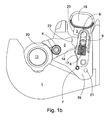
- Figure 1b
- The pull catch has been raised and locked on top of the lower tubular pin. The locking catch is then free to rotate.
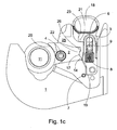
- Figure 1c
- When an implement is uncoupled, the locking catch rotates and automatically releases the pulling catch from the lock of the upper position.
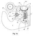
- Figure Id
- The implement has been completely detached form the hook and both the pull catch and the locking catch are in the lower position.
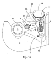
- Figure 1e
- When an implement is coupled, the locking catch causes the pull catch to rise by an amount that is greatest immediately before the locking catch locks.
- Figures 2a - 2b
- A second embodiment, equipped with an operating device operating the operating lever.
- In the figures, the coupling hook according to the invention is shown without a cover, which in the final product is welded onto the coupling hook. In addition, the coupling hook (
Category 3, ISO 11001) is shown slightly smaller than in reality. - The coupling hook itself is also attached to the lower arm by welding. The coupling hook includes a
body 1, in which there is acoupling throat 27 and ahousing 25,Figure 1a . The operating mechanism of thecatch 2 is mainly in thehousing 25. Thecoupling throat 27 is conventional and is arranged particularly to receive thecoupling ball 11. Usually the coupling ball is installed permanently in the implement, or is fitted to a conventional three-point-coupling pin. As such, a quick coupling can be made even without a coupling ball, which is, however, not to be recommended. In addition, with the aid of the coupling ball possible small differences of angle between the pin and the lower arm can be eliminated. In the figures, the coupling ball is marked with thereference number 11. - The
housing 25, to which thecatch 2 together with its operating mechanism is fitted, is formed in the coupling hook, which is manufactured as a forged piece. Thecatch 2 is pivoted in thehousing 25 with the aid of apin 4. Thepin 4 is a very asymmetrical position close to thecoupling throat 27. Thecatch 2 extends far inside the housing and always seeks to rotate with the aid of gravity to receive the coupling ball, i.e. its end next to the housing tends to drop downwards. In the position ofFigure 1a , the upper lobe 2.3 of thecatch 2 protrudes from the opening of thehousing 25 on top of thecoupling ball 11 and prevents thecoupling ball 11 from rising out of thecoupling throat 27, if the rotation of thecatch 2 is prevented. - According to
Figure 1a , thecounter surface 23 of the operating lever prevents thesurface 22 of thecatch 2 from moving and rotating, thus fully ensuring the retention of thecoupling ball 11 in its coupling throat. Thecounter surface 23 receives the force and theoperating lever 3 transmits it to thepin 6 of the housing. Thesupport surface 20 of thecatch 2 on thecoupling ball 11 side covers 60 - 120°, preferably 80 - 100° of the circumference of thecoupling ball 11. - Being restricted by the
pin 6 and theslot 9, theoperating lever 3 can move in different directions in the housing, except that in its lower position thepin 7 restricts its area of movement. Thecompression spring 9 seeks to push the operating lever downwards to the locking position, unless it is lifted on top of thepin 7 according toFigure 1b . - According to
Figure 1b , when theoperating lever 3 is lifted off thelower surface 19 on top of thepin 7, thecatch 2 can now rotate freely and the ball can rise out of the coupling throat. However, it should be noted that, when the catch rotates, thelobe 14 of the catch immediately begins to push on thesurface 17 and thus push theoperating lever 3 off thepin 7. Once thatsurface 19 of thecatch 2 finally slides off the top of the pin 7 (Figure 1c ), theoperating lever 3 drops downwards with the aid of thespring 8 and gravity, until thelobe 21 of theoperating lever 3 meets the lobe 26 (not shown) of thecatch 2. As the catch rotates, it continues to drop, until thepin 6 is at the upper end of theslot 9. - Once the
coupling ball 11 is removed entirely,Figure 1d , the hook remains in a state in which theoperating lever 3 is ready in the locking position, but thecatch 2 is ready to receive a coupling ball. As it drops, this rotates thecatch 2, which with the aid of thelobe 26 lifts theoperating lever 3 by thelobe 21 sufficiently for the saidsurfaces Figure 1a , in which no amount of loading of thecoupling ball 11 will open the catch mechanism. - Once the ball is in the ball housing of the hook, the locking catch is locked by the pull catch, i.e. it cannot rotate, despite the force acting on the ball.
- In
Figures 2a ,2b and2c , the catch mechanism itself is otherwise the same as in the above, except that the coupling hook is equipped with ahydraulic operating device 29, which in this case is installed in a vertically drilled hole in the arm. The same reference numbers as above are used for components that are functionally similar. In these figures, the end of thelower arm 26 is shown by broken lines. The weight distribution of thecatch 2 is further emphasized by means of a recess 2.1, by means of which the weight is reduced on the coupling-throat side. According to the figure, thecatch 2 weighs 200 g in a coupling hook according to Category 3 (coupling ball D = 64 mm). The diameter of thepin 14 is 12 mm and the moment measured from the catch 0,02 Nm, i.e. relative to its weight (200 g) 0,1 Nm/kg. This value should generally be 0,03 - 0,3, preferably in the range 0,06 - 0,15 Nm/kg, so that thecatch 2 will rotate reliably with the aid of gravity. Naturally, the catch can be equipped with a spring to rotate it, which will, however, complicate the construction. - The operating
lever 3 can move vertically in theslot 9 guided by thepin 6. In this case, the operatingdevice 29 is hydraulic and has apiston 34, which is sealed in a cylinder by means of aring seal 35. The hydraulic pressure is brought to theconnector 36. The piston rod 33 drives apin 32, which in turn drives thelower fork 31 of the operating lever. There is a horizontally drilled hole in the rod for thepin 32. According toFigures 2a and2b , the operatinglever 3 raised by the operatingdevice 29 does not prevent thecatch 2 from rotating and the locking opening. Thus the coupling ball can rise out of the throat. When thepin 32 raising the operatinglever 3 is lowered (not shown), the mechanism again remains automatically in the locking state to receive thecoupling ball 11.
Claims (7)
- Coupling hook, which is intended to attach an implement to a tractor by means of a coupling ball (11) or similar, which coupling hook includes- a body (1), in which there is a housing (25) for a catch mechanism and a coupling throat (27) arranged to receive particularly the said coupling ball (11);- a catch (2) rotating around a fixed pin (4) in the housing (25), the end of which catch protrudes out of the housing (25) to the coupling throat (27), in order to lock the coupling ball (11) into the coupling throat (27), whereas in the free position the catch (2) can rotate, thus permitting the coupling ball (11) to rise out of the coupling throat (27);- an operating lever (3) operating the catch (2), for moving the catch (2) from the retention position to the free position and back again, and in which retention position the operating lever (3) prevents the catch (2) from rotating out of the coupling throat,characterized in that the catch (2) is arranged to return the operating lever (3) to the locking position, when the coupling ball (11) rotates the catch as the coupling ball rises out of the coupling throat (27).
- Coupling hook according to Claim 1, characterized in that the operating lever (3) includes a counter surface (23) and the catch (2) a locking surface (22), which are arranged to lock the catch (2) when the operating lever (3) is in the locking position.
- Coupling hook according to Claim 1 or 2, characterized in that the catch (2) includes a guide lobe (26) contacting an auxiliary lobe (21) of the operating lever (3) for holding it up at the start of the return movement, before the catch (2) has rotated to close to its locking position, after having received the coupling ball (11).
- Coupling hook according to Claim 3, characterized in that the auxiliary lobe (21) of the operating lever is formed in connection with the counter surface (23).
- Coupling hook according to any of Claims 1 - 4, characterized in that the catch (2) is pivoted on one side, so that it will try to open with the aid of gravity.
- Coupling hook according to Claim 5, characterized in that the pivot (4) carrying the catch (2) is at the end of the coupling ball (11) side, while the opposite end extends asymmetrically deep inside the housing (25).
- Coupling hook according to Claim 5 or 6, characterized in that the support surface (20) of the catch (2) on the coupling ball (11) side covers 60 - 120°, preferably 80 - 100° of the circumference of the coupling ball (11).
Applications Claiming Priority (1)
| Application Number | Priority Date | Filing Date | Title |
|---|---|---|---|
| FI20075340A FI20075340L (en) | 2007-05-10 | 2007-05-10 | Coupling claw for a drawbar for a three-point hitch on a tractor |
Publications (2)
| Publication Number | Publication Date |
|---|---|
| EP1990220A1 EP1990220A1 (en) | 2008-11-12 |
| EP1990220B1 true EP1990220B1 (en) | 2010-07-14 |
Family
ID=38069507
Family Applications (1)
| Application Number | Title | Priority Date | Filing Date |
|---|---|---|---|
| EP08155666A Active EP1990220B1 (en) | 2007-05-10 | 2008-05-06 | Coupling hook particularly for the lower arms of a three-point linkage of a tractor |
Country Status (5)
| Country | Link |
|---|---|
| EP (1) | EP1990220B1 (en) |
| CN (1) | CN101305651B (en) |
| AT (1) | ATE473874T1 (en) |
| DE (1) | DE602008001748D1 (en) |
| FI (1) | FI20075340L (en) |
Families Citing this family (3)
| Publication number | Priority date | Publication date | Assignee | Title |
|---|---|---|---|---|
| DE202010016051U1 (en) * | 2010-12-02 | 2012-03-05 | Hans Sauermann | Coupling hook for a lower link of a tractor |
| CN103600628B (en) * | 2013-11-29 | 2016-01-27 | 武汉圣翌电动工业车辆有限公司 | A kind of hauling hook device of towing vehicle |
| WO2021229594A1 (en) | 2020-05-14 | 2021-11-18 | Uniparts India Limited | Lower link hook |
Family Cites Families (5)
| Publication number | Priority date | Publication date | Assignee | Title |
|---|---|---|---|---|
| DE2414441C2 (en) | 1974-03-26 | 1975-10-30 | Jean Walterscheid Gmbh, 5204 Lohmar | Locking device for coupling hooks on the three-point linkage of a tractor |
| FR2444396A1 (en) * | 1978-12-22 | 1980-07-18 | Herriau Sa | AUTOMATIC HITCHING DEVICE |
| GB2192122B (en) | 1986-07-02 | 1989-12-13 | Gkn Sankey Ltd | Coupling hook |
| DE3912414C1 (en) | 1989-04-15 | 1990-06-13 | Jean Walterscheid Gmbh, 5204 Lohmar, De | |
| DE3928699A1 (en) | 1989-08-30 | 1991-03-14 | Walterscheid Gmbh Jean | CLUTCH HOOK FOR LOWER ARM |
-
2007
- 2007-05-10 FI FI20075340A patent/FI20075340L/en not_active Application Discontinuation
-
2008
- 2008-05-06 DE DE602008001748T patent/DE602008001748D1/en active Active
- 2008-05-06 EP EP08155666A patent/EP1990220B1/en active Active
- 2008-05-06 AT AT08155666T patent/ATE473874T1/en not_active IP Right Cessation
- 2008-05-09 CN CN2008100967372A patent/CN101305651B/en active Active
Also Published As
| Publication number | Publication date |
|---|---|
| FI20075340A7 (en) | 2008-11-11 |
| CN101305651B (en) | 2012-06-27 |
| ATE473874T1 (en) | 2010-07-15 |
| FI20075340A0 (en) | 2007-05-10 |
| DE602008001748D1 (en) | 2010-08-26 |
| FI20075340L (en) | 2008-11-11 |
| CN101305651A (en) | 2008-11-19 |
| EP1990220A1 (en) | 2008-11-12 |
Similar Documents
| Publication | Publication Date | Title |
|---|---|---|
| US5050684A (en) | Coupling hook | |
| CN112368448B (en) | Coupling device | |
| EP1990220B1 (en) | Coupling hook particularly for the lower arms of a three-point linkage of a tractor | |
| US4071263A (en) | Coupling hook for a three-point connection on a tractor | |
| US20240301649A1 (en) | Coupler | |
| US4477101A (en) | Arrangement for coupling an implement to a tractor | |
| US10039262B2 (en) | Livestock head holder with singular operating lever for closing, unlocking and opening same | |
| CA1040678A (en) | Coupling hook for a three-point connection on a tractor | |
| US20070145719A1 (en) | Towing mechanism | |
| AU2012326315B2 (en) | Remote activation of scissor lift cylinder prop | |
| GB2509303A (en) | Coupler | |
| US5037123A (en) | Automatic trailer hitch | |
| EP1849632A1 (en) | Coupler jaw intended for the three-point coupling of a tractor | |
| CN214194314U (en) | Sweeping disc device for sweeping vehicle | |
| CA1114223A (en) | Draft arm extension stop | |
| JP2008008095A (en) | Vehicle stop device | |
| EP2159083B1 (en) | Ball coupling | |
| KR20030045181A (en) | A latch mechanism | |
| ES2559285T3 (en) | Hitching arrangement for a towing vehicle, comprising a receiving hook body of a hitching element of a towed vehicle | |
| GB2610148A (en) | Coupler | |
| CN120191831A (en) | Anti-unhooking hook | |
| CA2325794C (en) | Fifth wheel ball hitch latching assembly | |
| JPH0724964Y2 (en) | Tractor hitch device | |
| JP2003325003A (en) | Implement-connecting apparatus | |
| GB2610147A (en) | Coupler |
Legal Events
| Date | Code | Title | Description |
|---|---|---|---|
| PUAI | Public reference made under article 153(3) epc to a published international application that has entered the european phase |
Free format text: ORIGINAL CODE: 0009012 |
|
| AK | Designated contracting states |
Kind code of ref document: A1 Designated state(s): AT BE BG CH CY CZ DE DK EE ES FI FR GB GR HR HU IE IS IT LI LT LU LV MC MT NL NO PL PT RO SE SI SK TR |
|
| AX | Request for extension of the european patent |
Extension state: AL BA MK RS |
|
| 17P | Request for examination filed |
Effective date: 20090430 |
|
| 17Q | First examination report despatched |
Effective date: 20090609 |
|
| AKX | Designation fees paid |
Designated state(s): AT BE BG CH CY CZ DE DK EE ES FI FR GB GR HR HU IE IS IT LI LT LU LV MC MT NL NO PL PT RO SE SI SK TR |
|
| GRAP | Despatch of communication of intention to grant a patent |
Free format text: ORIGINAL CODE: EPIDOSNIGR1 |
|
| GRAS | Grant fee paid |
Free format text: ORIGINAL CODE: EPIDOSNIGR3 |
|
| GRAA | (expected) grant |
Free format text: ORIGINAL CODE: 0009210 |
|
| RIN1 | Information on inventor provided before grant (corrected) |
Inventor name: KUMPUKALLIO, PEKKA Inventor name: PUUSTINEN, SAMI Inventor name: VIIKKI, TIMO Inventor name: VIIKKI, PAAVO |
|
| AK | Designated contracting states |
Kind code of ref document: B1 Designated state(s): AT BE BG CH CY CZ DE DK EE ES FI FR GB GR HR HU IE IS IT LI LT LU LV MC MT NL NO PL PT RO SE SI SK TR |
|
| REG | Reference to a national code |
Ref country code: GB Ref legal event code: FG4D |
|
| REG | Reference to a national code |
Ref country code: CH Ref legal event code: EP |
|
| REG | Reference to a national code |
Ref country code: IE Ref legal event code: FG4D |
|
| REF | Corresponds to: |
Ref document number: 602008001748 Country of ref document: DE Date of ref document: 20100826 Kind code of ref document: P |
|
| REG | Reference to a national code |
Ref country code: NL Ref legal event code: VDEP Effective date: 20100714 |
|
| LTIE | Lt: invalidation of european patent or patent extension |
Effective date: 20100714 |
|
| PG25 | Lapsed in a contracting state [announced via postgrant information from national office to epo] |
Ref country code: NO Free format text: LAPSE BECAUSE OF FAILURE TO SUBMIT A TRANSLATION OF THE DESCRIPTION OR TO PAY THE FEE WITHIN THE PRESCRIBED TIME-LIMIT Effective date: 20101014 Ref country code: NL Free format text: LAPSE BECAUSE OF FAILURE TO SUBMIT A TRANSLATION OF THE DESCRIPTION OR TO PAY THE FEE WITHIN THE PRESCRIBED TIME-LIMIT Effective date: 20100714 Ref country code: AT Free format text: LAPSE BECAUSE OF FAILURE TO SUBMIT A TRANSLATION OF THE DESCRIPTION OR TO PAY THE FEE WITHIN THE PRESCRIBED TIME-LIMIT Effective date: 20100714 Ref country code: LT Free format text: LAPSE BECAUSE OF FAILURE TO SUBMIT A TRANSLATION OF THE DESCRIPTION OR TO PAY THE FEE WITHIN THE PRESCRIBED TIME-LIMIT Effective date: 20100714 |
|
| PG25 | Lapsed in a contracting state [announced via postgrant information from national office to epo] |
Ref country code: PL Free format text: LAPSE BECAUSE OF FAILURE TO SUBMIT A TRANSLATION OF THE DESCRIPTION OR TO PAY THE FEE WITHIN THE PRESCRIBED TIME-LIMIT Effective date: 20100714 Ref country code: HR Free format text: LAPSE BECAUSE OF FAILURE TO SUBMIT A TRANSLATION OF THE DESCRIPTION OR TO PAY THE FEE WITHIN THE PRESCRIBED TIME-LIMIT Effective date: 20100714 Ref country code: BG Free format text: LAPSE BECAUSE OF FAILURE TO SUBMIT A TRANSLATION OF THE DESCRIPTION OR TO PAY THE FEE WITHIN THE PRESCRIBED TIME-LIMIT Effective date: 20101014 Ref country code: CY Free format text: LAPSE BECAUSE OF FAILURE TO SUBMIT A TRANSLATION OF THE DESCRIPTION OR TO PAY THE FEE WITHIN THE PRESCRIBED TIME-LIMIT Effective date: 20100714 Ref country code: SI Free format text: LAPSE BECAUSE OF FAILURE TO SUBMIT A TRANSLATION OF THE DESCRIPTION OR TO PAY THE FEE WITHIN THE PRESCRIBED TIME-LIMIT Effective date: 20100714 Ref country code: IS Free format text: LAPSE BECAUSE OF FAILURE TO SUBMIT A TRANSLATION OF THE DESCRIPTION OR TO PAY THE FEE WITHIN THE PRESCRIBED TIME-LIMIT Effective date: 20101114 |
|
| PG25 | Lapsed in a contracting state [announced via postgrant information from national office to epo] |
Ref country code: BE Free format text: LAPSE BECAUSE OF FAILURE TO SUBMIT A TRANSLATION OF THE DESCRIPTION OR TO PAY THE FEE WITHIN THE PRESCRIBED TIME-LIMIT Effective date: 20100714 Ref country code: GR Free format text: LAPSE BECAUSE OF FAILURE TO SUBMIT A TRANSLATION OF THE DESCRIPTION OR TO PAY THE FEE WITHIN THE PRESCRIBED TIME-LIMIT Effective date: 20101015 Ref country code: LV Free format text: LAPSE BECAUSE OF FAILURE TO SUBMIT A TRANSLATION OF THE DESCRIPTION OR TO PAY THE FEE WITHIN THE PRESCRIBED TIME-LIMIT Effective date: 20100714 Ref country code: SE Free format text: LAPSE BECAUSE OF FAILURE TO SUBMIT A TRANSLATION OF THE DESCRIPTION OR TO PAY THE FEE WITHIN THE PRESCRIBED TIME-LIMIT Effective date: 20100714 |
|
| PG25 | Lapsed in a contracting state [announced via postgrant information from national office to epo] |
Ref country code: DK Free format text: LAPSE BECAUSE OF FAILURE TO SUBMIT A TRANSLATION OF THE DESCRIPTION OR TO PAY THE FEE WITHIN THE PRESCRIBED TIME-LIMIT Effective date: 20100714 |
|
| PLBE | No opposition filed within time limit |
Free format text: ORIGINAL CODE: 0009261 |
|
| STAA | Information on the status of an ep patent application or granted ep patent |
Free format text: STATUS: NO OPPOSITION FILED WITHIN TIME LIMIT |
|
| PG25 | Lapsed in a contracting state [announced via postgrant information from national office to epo] |
Ref country code: CZ Free format text: LAPSE BECAUSE OF FAILURE TO SUBMIT A TRANSLATION OF THE DESCRIPTION OR TO PAY THE FEE WITHIN THE PRESCRIBED TIME-LIMIT Effective date: 20100714 Ref country code: EE Free format text: LAPSE BECAUSE OF FAILURE TO SUBMIT A TRANSLATION OF THE DESCRIPTION OR TO PAY THE FEE WITHIN THE PRESCRIBED TIME-LIMIT Effective date: 20100714 Ref country code: RO Free format text: LAPSE BECAUSE OF FAILURE TO SUBMIT A TRANSLATION OF THE DESCRIPTION OR TO PAY THE FEE WITHIN THE PRESCRIBED TIME-LIMIT Effective date: 20100714 Ref country code: SK Free format text: LAPSE BECAUSE OF FAILURE TO SUBMIT A TRANSLATION OF THE DESCRIPTION OR TO PAY THE FEE WITHIN THE PRESCRIBED TIME-LIMIT Effective date: 20100714 |
|
| 26N | No opposition filed |
Effective date: 20110415 |
|
| PG25 | Lapsed in a contracting state [announced via postgrant information from national office to epo] |
Ref country code: ES Free format text: LAPSE BECAUSE OF FAILURE TO SUBMIT A TRANSLATION OF THE DESCRIPTION OR TO PAY THE FEE WITHIN THE PRESCRIBED TIME-LIMIT Effective date: 20101025 |
|
| REG | Reference to a national code |
Ref country code: DE Ref legal event code: R097 Ref document number: 602008001748 Country of ref document: DE Effective date: 20110415 |
|
| PG25 | Lapsed in a contracting state [announced via postgrant information from national office to epo] |
Ref country code: MC Free format text: LAPSE BECAUSE OF NON-PAYMENT OF DUE FEES Effective date: 20110531 Ref country code: MT Free format text: LAPSE BECAUSE OF FAILURE TO SUBMIT A TRANSLATION OF THE DESCRIPTION OR TO PAY THE FEE WITHIN THE PRESCRIBED TIME-LIMIT Effective date: 20100714 |
|
| REG | Reference to a national code |
Ref country code: IE Ref legal event code: MM4A |
|
| PG25 | Lapsed in a contracting state [announced via postgrant information from national office to epo] |
Ref country code: IE Free format text: LAPSE BECAUSE OF NON-PAYMENT OF DUE FEES Effective date: 20110506 |
|
| REG | Reference to a national code |
Ref country code: CH Ref legal event code: PL |
|
| PG25 | Lapsed in a contracting state [announced via postgrant information from national office to epo] |
Ref country code: CH Free format text: LAPSE BECAUSE OF NON-PAYMENT OF DUE FEES Effective date: 20120531 Ref country code: LI Free format text: LAPSE BECAUSE OF NON-PAYMENT OF DUE FEES Effective date: 20120531 |
|
| PG25 | Lapsed in a contracting state [announced via postgrant information from national office to epo] |
Ref country code: LU Free format text: LAPSE BECAUSE OF NON-PAYMENT OF DUE FEES Effective date: 20110506 |
|
| PG25 | Lapsed in a contracting state [announced via postgrant information from national office to epo] |
Ref country code: PT Free format text: LAPSE BECAUSE OF NON-PAYMENT OF DUE FEES Effective date: 20100714 |
|
| PG25 | Lapsed in a contracting state [announced via postgrant information from national office to epo] |
Ref country code: TR Free format text: LAPSE BECAUSE OF FAILURE TO SUBMIT A TRANSLATION OF THE DESCRIPTION OR TO PAY THE FEE WITHIN THE PRESCRIBED TIME-LIMIT Effective date: 20100714 |
|
| PG25 | Lapsed in a contracting state [announced via postgrant information from national office to epo] |
Ref country code: HU Free format text: LAPSE BECAUSE OF FAILURE TO SUBMIT A TRANSLATION OF THE DESCRIPTION OR TO PAY THE FEE WITHIN THE PRESCRIBED TIME-LIMIT Effective date: 20100714 |
|
| REG | Reference to a national code |
Ref country code: FR Ref legal event code: PLFP Year of fee payment: 9 |
|
| REG | Reference to a national code |
Ref country code: FR Ref legal event code: PLFP Year of fee payment: 10 |
|
| REG | Reference to a national code |
Ref country code: FR Ref legal event code: PLFP Year of fee payment: 11 |
|
| PGFP | Annual fee paid to national office [announced via postgrant information from national office to epo] |
Ref country code: DE Payment date: 20250521 Year of fee payment: 18 |
|
| PGFP | Annual fee paid to national office [announced via postgrant information from national office to epo] |
Ref country code: GB Payment date: 20250530 Year of fee payment: 18 |
|
| PGFP | Annual fee paid to national office [announced via postgrant information from national office to epo] |
Ref country code: IT Payment date: 20250527 Year of fee payment: 18 |
|
| PGFP | Annual fee paid to national office [announced via postgrant information from national office to epo] |
Ref country code: FR Payment date: 20250528 Year of fee payment: 18 |
|
| PGFP | Annual fee paid to national office [announced via postgrant information from national office to epo] |
Ref country code: FI Payment date: 20260317 Year of fee payment: 19 |