EP1992822A1 - Vacuum divider for differential pumping of a vacuum system - Google Patents
Vacuum divider for differential pumping of a vacuum system Download PDFInfo
- Publication number
- EP1992822A1 EP1992822A1 EP20080103846 EP08103846A EP1992822A1 EP 1992822 A1 EP1992822 A1 EP 1992822A1 EP 20080103846 EP20080103846 EP 20080103846 EP 08103846 A EP08103846 A EP 08103846A EP 1992822 A1 EP1992822 A1 EP 1992822A1
- Authority
- EP
- European Patent Office
- Prior art keywords
- vacuum
- divider
- turbo
- molecular pump
- rotor
- Prior art date
- Legal status (The legal status is an assumption and is not a legal conclusion. Google has not performed a legal analysis and makes no representation as to the accuracy of the status listed.)
- Granted
Links
Images


Classifications
-
- F—MECHANICAL ENGINEERING; LIGHTING; HEATING; WEAPONS; BLASTING
- F04—POSITIVE - DISPLACEMENT MACHINES FOR LIQUIDS; PUMPS FOR LIQUIDS OR ELASTIC FLUIDS
- F04D—NON-POSITIVE-DISPLACEMENT PUMPS
- F04D19/00—Axial-flow pumps
- F04D19/02—Multi-stage pumps
- F04D19/04—Multi-stage pumps specially adapted to the production of a high vacuum, e.g. molecular pumps
- F04D19/042—Turbomolecular vacuum pumps
-
- F—MECHANICAL ENGINEERING; LIGHTING; HEATING; WEAPONS; BLASTING
- F04—POSITIVE - DISPLACEMENT MACHINES FOR LIQUIDS; PUMPS FOR LIQUIDS OR ELASTIC FLUIDS
- F04D—NON-POSITIVE-DISPLACEMENT PUMPS
- F04D29/00—Details, component parts, or accessories
- F04D29/05—Shafts or bearings, or assemblies thereof, specially adapted for elastic fluid pumps
- F04D29/056—Bearings
-
- F—MECHANICAL ENGINEERING; LIGHTING; HEATING; WEAPONS; BLASTING
- F04—POSITIVE - DISPLACEMENT MACHINES FOR LIQUIDS; PUMPS FOR LIQUIDS OR ELASTIC FLUIDS
- F04D—NON-POSITIVE-DISPLACEMENT PUMPS
- F04D29/00—Details, component parts, or accessories
- F04D29/40—Casings; Connections of working fluid
- F04D29/42—Casings; Connections of working fluid for radial or helico-centrifugal pumps
- F04D29/4206—Casings; Connections of working fluid for radial or helico-centrifugal pumps especially adapted for elastic fluid pumps
- F04D29/4213—Casings; Connections of working fluid for radial or helico-centrifugal pumps especially adapted for elastic fluid pumps suction ports
-
- F—MECHANICAL ENGINEERING; LIGHTING; HEATING; WEAPONS; BLASTING
- F04—POSITIVE - DISPLACEMENT MACHINES FOR LIQUIDS; PUMPS FOR LIQUIDS OR ELASTIC FLUIDS
- F04D—NON-POSITIVE-DISPLACEMENT PUMPS
- F04D29/00—Details, component parts, or accessories
- F04D29/60—Mounting; Assembling; Disassembling
- F04D29/601—Mounting; Assembling; Disassembling specially adapted for elastic fluid pumps
-
- F—MECHANICAL ENGINEERING; LIGHTING; HEATING; WEAPONS; BLASTING
- F05—INDEXING SCHEMES RELATING TO ENGINES OR PUMPS IN VARIOUS SUBCLASSES OF CLASSES F01-F04
- F05D—INDEXING SCHEME FOR ASPECTS RELATING TO NON-POSITIVE-DISPLACEMENT MACHINES OR ENGINES, GAS-TURBINES OR JET-PROPULSION PLANTS
- F05D2250/00—Geometry
- F05D2250/50—Inlet or outlet
- F05D2250/51—Inlet
-
- H—ELECTRICITY
- H01—ELECTRIC ELEMENTS
- H01J—ELECTRIC DISCHARGE TUBES OR DISCHARGE LAMPS
- H01J49/00—Particle spectrometers or separator tubes
- H01J49/02—Details
- H01J49/24—Vacuum systems, e.g. maintaining desired pressures
-
- Y—GENERAL TAGGING OF NEW TECHNOLOGICAL DEVELOPMENTS; GENERAL TAGGING OF CROSS-SECTIONAL TECHNOLOGIES SPANNING OVER SEVERAL SECTIONS OF THE IPC; TECHNICAL SUBJECTS COVERED BY FORMER USPC CROSS-REFERENCE ART COLLECTIONS [XRACs] AND DIGESTS
- Y10—TECHNICAL SUBJECTS COVERED BY FORMER USPC
- Y10T—TECHNICAL SUBJECTS COVERED BY FORMER US CLASSIFICATION
- Y10T137/00—Fluid handling
- Y10T137/2496—Self-proportioning or correlating systems
- Y10T137/2514—Self-proportioning flow systems
- Y10T137/2521—Flow comparison or differential response
- Y10T137/2524—Flow dividers [e.g., reversely acting controls]
Definitions
- the invention relates to the field of vacuum systems, and more specifically to differential pumping of vacuum systems.
- Typical turbo-molecular pumps such as those manufactured by BOC Edwards of Crawley, West Wales, United Kingdom (“Edwards”) and Pfeiffer Vacuum Inc. of NH, USA (“Pfeiffer”) have a single high vacuum inlet at the top of the rotor stack designed to evacuate a single vacuum region.
- turbo-molecular pumps also have inter-stage ports that allow for pumping of more than one vacuum region.
- Edwards EXT255H is a compound molecular pump with a high-vacuum stage and a drag stage (see US Patent 6709228B2 to Stuart ). This configuration allows for pumping on two vacuum regions, one high vacuum and one low vacuum. However, an additional one of these pumps would be required to evacuate a second high vacuum region.
- turbo-molecular pumps such as the Edwards EXT200/200/30, which create a second high vacuum stage by placing a port in the side of the turbo-molecular section of the pump, at a distance of a few rotor blade heights downstream from the high vacuum inlet.
- turbo-molecular pumps such as the Pfeiffer TMH 262-020 YP
- a support structure above the top rotor blades in the high vacuum inlet.
- This structure is used to support the rotor shaft bearing at the top of the rotor stack.
- the gap between the structure and the rotor blades is roughly one-half the width of the support.
- this structure is only used as a support structure and does not result in the division of the turbo-molecular pump's high-vacuum inlet into more than one vacuum region for differential pumping.
- the cost of the pumping system in instruments using a vacuum system can be a significant portion of the total cost of the instrument.
- the addition of another vacuum pump or the use of a more costly vacuum pump can be a significant cost disadvantage. It can also result in bulky and difficult to manage vacuum systems.
- the present invention which provides a divider in the high vacuum inlet of a turbo-molecular pump allowing for the evacuation of a second high vacuum region without a significant increase in the cost of the pumping system.
- an embodiment of the invention is a vacuum divider positioned between rotor blades of a turbo-molecular pump and a vacuum manifold formed from multiple vacuum chambers.
- a first coupling aperture passes through the vacuum divider and allows gas to pass from a first of the multiple vacuum chambers to the turbo-molecular pump.
- a second coupling aperture passes through the vacuum divider and allows gas to pass from a second of the multiple vacuum chambers to the turbo-molecular pump.
- the present invention combines a vacuum divider 101 and a vacuum manifold 201 with a turbo-molecular pump 105 in order to pump a differential vacuum between several vacuum chambers of a portion of a vacuum system 100.
- This invention can dramatically decrease the cost of the vacuum system by allowing a single relatively inexpensive turbo-molecular pump, rather than several independent pumps, to be used to pump this differential vacuum.
- this invention provides a system much more compact than the prior-art.
- a vacuum divider 101 is installed at a high vacuum inlet 103 of a turbo-molecular pump 105 in close proximity to the top of rotor blades 107 of the turbo-molecular pump 105.
- the turbo-molecular pump 105 can be a Pfeiffer THM 261-020 YP, for example.
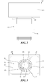
- FIGURE 2 is a side plan view of the portion of the vacuum system 100 with an added vacuum manifold 201 attached to form a vacuum assembly 200.
- the vacuum divider 101 is seated between the rotor blades 107 of turbo-molecular pump 105 and the vacuum manifold 201.
- the vacuum divider 101 is shown installed at the high vacuum inlet 103, but in other embodiments it can be located up-stream or downstream from the high vacuum inlet 103 so long as it is located between the rotor blades 107 of turbo-molecular pump 105 and the vacuum manifold 201 at a position relatively close to the rotor blades 107.
- the vacuum divider 101 can be attached to the turbo-molecular pump 105 and the vacuum manifold 201 by a vacuum-tight seal.
- a vacuum-tight seal is defined as a seal where the leak rate into a vacuum chamber through the seal is small enough so as not to substantially affect the vacuum level within the vacuum chamber.
- Removable, vacuum-tight connections can be used to connect the vacuum divider 101 to the turbo-molecular pump 105 and/or vacuum manifold 201 using copper gasket / knife edge vacuum connections, o-ring connections, zero-clearance matching flat surfaces, overlapping joints, or other methods known in the art.
- the vacuum divider 101 can be welded to either the turbo-molecular pump 105 or the vacuum manifold 201 or both of them.
- the vacuum divider 101 is integral with the turbo-molecular pump 105 or the vacuum manifold 201.
- the vacuum divider 101 can be machined as a single piece with either the turbo-molecular pump 105 or the vacuum manifold 201 or both of them. This eliminates the need to fabricate the vacuum divider 101 as a separate part.
- FIGURE 3 is a top plan view of the vacuum assembly 200.
- a first coupling aperture 301 and a second coupling aperture 303 pass through the vacuum divider 101.
- These apertures 301, 303 in the vacuum divider 101 are formed by radially extending ribs 305, 307.
- the ribs 305, 307 extend from a divider central portion 309 (also shown in FIGURE 1 ) which covers the rotor shaft area at the top of the rotor stack.
- the apertures are additionally formed by aperture walls 311 through the vacuum divider 101.
- the first and second coupling apertures 301, 303 are separated by the rib 305 crossing the vacuum divider 101 and also by the rib 307 crossing the vacuum divider 101.
- the vacuum manifold 201 includes a first vacuum chamber 313 and a second vacuum chamber 315.
- a bulkhead wall 317 of the vacuum manifold 201 divides the manifold 201 into the first vacuum chamber 313 and the second vacuum chamber 315.
- the bulkhead wall 317 follows and is sealed with a vacuum-tight seal to the ribs 305, 307.
- the ribs 305, 307 are aligned with the bulkhead wall 317 so that the first coupling aperture 301 and first vacuum chamber 313 form a first continuous space and the second coupling aperture 303 and the second vacuum chamber 315 form a second continuous space.
- the first coupling aperture 301 is fixed with a vacuum-tight seal to the first vacuum chamber 313 and the second coupling aperture 303 is fixed with a vacuum-tight seal to the second vacuum chamber 315. Also, the first coupling aperture 301 allows gas to pass from the first vacuum chamber 313 to the turbo-molecular pump 105 and the second coupling aperture 301 allows gas to pass from the second vacuum chamber 313 to the turbo-molecular pump 105.
- a "pump inlet area allocation” is defined to be the area of each coupling aperture expressed as a percentage of the total area of all coupling apertures.
- the pump inlet area allocation of all apertures should add up to 100%.
- the ribs 305, 307 and the divider central portion 309 are not considered in the calculation of pump inlet area.
- the pump inlet area allocation can be set at 32% for the vacuum chamber 313 and 68% for the vacuum chamber 315, for example.
- the vacuum manifold 201 includes a floor 318 with it's own coupling apertures passing through the floor and corresponding to the first and second coupling apertures 301, 303 of the vacuum divider 101.
- the invention also encompasses embodiments having additional coupling apertures passing through the vacuum divider for allowing gas to pass from additional ones of the multiple vacuum chambers, through the vacuum divider 101 and into the turbo-molecular pump 105.
- the vacuum divider 101 can include three or more coupling apertures and the vacuum manifold 201 can include three or more vacuum chambers. Then each of the coupling apertures allows gas to pass from one of the vacuum chambers, through the vacuum divider 101 and into the turbo-molecular pump 105.
- the single turbo-molecular pump 105 can thereby pump three or more vacuum chambers of the vacuum system to produce three or more different vacuum pressures.
- FIGURE 4 is a bottom perspective view of an embodiment of the vacuum divider 101 having a flat rotor-blade-directed face 401 of the ribs 305, 307 separating the coupling apertures 301, 303.
- the vacuum divider 101 is located between the rotor blades 107 of the turbo-molecular pump 105 and the vacuum manifold 201 at a position relatively close to the rotor blades 107. This distance relative to the rotor blades 107 is preferably fixed so that the closest distance between the vacuum divider 101 and the rotor blades of the turbo-molecular pump 105 is less than 30% of a minimum width 403 of the ribs 305, 307.
- This gap distance 901 is shown schematically in FIGURE 9 as the closest distance 901 (note: the figure is not drawn to scale).
- the minimum width is the minimum width 403 of the rotor-blade-directed face 401 separating the coupling apertures.
- the position of the vacuum divider 101 is fixed relative to the turbo-molecular pump 105 so that the closest distance 901 between the flat rotor-blade-directed face 401 and the rotor blades of the turbo-molecular pump 105 is less than 30% of the minimum width 403 of the rotor-blade-directed face 401 separating the coupling apertures.
- the vacuum divider 101 of FIGURE 4 is inserted into the high vacuum inlet 103 of the turbo-molecular pump 105 of FIGURE 2 , where the turbo-molecular pump can be the Edwards model EXT255H.
- the divider can then be mated with a matching flat surface on the vacuum manifold 201.
- O-rings can be used to seal the turbo-molecular pump flange and the vacuum divider 101 to the vacuum manifold 201.
- the two distinct vacuum chambers 313, 315 are created.
- FIGURE 5 is a bottom perspective view of another embodiment of the vacuum divider 101 having a rotor-blade-directed face 503 of the ribs 305, 307 separating the coupling apertures 301, 303, similar to the embodiment of FIGURE 4 , but with the addition of a channel 501 formed in the rotor-blade-directed face 503.
- the purpose of the channel 501 of this embodiment of the vacuum divider 101 is to create an intermediate vacuum region between the two vacuum chambers 313, 315 of the vacuum manifold 201. This decreases the amount of gas that can pass between the apertures 301, 303 and thereby improves the differential pumping between the vacuum chambers 313, 315.
- FIGURE 6 is a top plan view of a variation 600 of the vacuum assembly 200 of FIGURE 3 .
- coupling apertures 601, 603 in the vacuum divider 621 are formed by bisecting ribs 605, 607, which extend from a divider central portion 609, and a bulkhead wall 617 of the vacuum manifold 619 follows along the ribs 605, 607.
- This embodiment results in the coupling apertures 601, 603 and vacuum chambers 613, 615 having different relative sizes and shapes as compared to the vacuum assembly 200 of FIGURE 3 .
- the pump inlet area allocation can be set at 60% for the vacuum chamber 613 and 40% for the vacuum chamber 615, for example.
- a precision leak valve was added to the vacuum chamber 313 to allow for an adjustable gas load.
- the vacuum chamber 315 had no external gas load. Thus, during the tests, the vacuum chamber 313 was at a higher pressure than the vacuum chamber 315.
- DPR Downward Pumping Ratio
- FIGURE 7 is a graph illustrating DPR (vertical axis) as a function of the pressure of the vacuum chamber 313 (horizontal axis) for an optimum combination of the parameters.
- the divider design of FIGURE 5 having the channel 501 was used.
- the distance between the rotor-blade-directed face 503 and the rotor blades 107 was set to 0.75mm.
- the pump inlet area allocation was set at 32% for the vacuum chamber 313 and 68% for the vacuum chamber 315.
- the pressure of the vacuum chamber 313 was increased by opening the precision leak valve and at each data point the DPR was calculated.
- the divider design of FIGURE 5 with the channel 501 formed in the rotor-blade-directed face 503 was found to produce a 6% to 14% improvement in the DPR compared to that of the divider of FIGURE 4 having the flat rotor-blade-directed face 401.
- the pump inlet area allocation had a significant effect on the DPR.
- the pump inlet area allocation was set at 68% for the vacuum chamber 313 and 32% for the vacuum chamber 315 and also set at 32% for the vacuum chamber 313 and 68% for the vacuum chamber 315.
- the DPR more than doubled when the pump inlet area allocation was switched from 68% for the vacuum chamber 313 and 32% for the vacuum chamber 315 to 32% for the vacuum chamber 313 and 68% for the vacuum chamber 315.
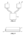
- FIGURE 8 is a diagrammatic view of a mass spectrometer system 801 utilizing the portion of the vacuum assembly 200 of FIGURE 2 to separately evacuate an ion optics chamber 803 and a mass analyzer chamber 805 to different vacuum pressures.
- the ion optics chamber 803 can contain an ion guide, a collision cell, or other ion optics elements.
- the ion optics chamber 803 can be evacuated through the first vacuum chamber 313 and the mass analyzer chamber 805 can be evacuated through the second vacuum chamber 315.
- the relative sizes of the coupling apertures 301, 303 can be adjustable.
- at least one of the coupling apertures 301, 303 can be an adjustable iris.
- the pump inlet area allocation can be varied and in this way, the relative pressures of the vacuum chambers 313, 315 and thereby the relative pressures of the ion optics chamber 803 and mass analyzer chamber 805 can be fine tuned.
- the measured DPRs of the vacuum chambers 313, 315 can be customized for particular applications.
- the DPRs can be adjusted to, for example, at least 2, 3, 4, 5, 6, 7, 8, 9, 10, 11, 12, 13, 14, 15, 16, 17, 18, 19 or 20.
- the gas referred to can be air or other gasses.
- the vacuum divider can be made from aluminum, stainless steel, high performance engineering plastic or other known materials.
Landscapes
- Engineering & Computer Science (AREA)
- Mechanical Engineering (AREA)
- General Engineering & Computer Science (AREA)
- Non-Positive Displacement Air Blowers (AREA)
Abstract
Description
- The invention relates to the field of vacuum systems, and more specifically to differential pumping of vacuum systems.
- Typical turbo-molecular pumps such as those manufactured by BOC Edwards of Crawley, West Sussex, United Kingdom ("Edwards") and Pfeiffer Vacuum Inc. of NH, USA ("Pfeiffer") have a single high vacuum inlet at the top of the rotor stack designed to evacuate a single vacuum region.
- Some turbo-molecular pumps also have inter-stage ports that allow for pumping of more than one vacuum region. For example, the Edwards EXT255H is a compound molecular pump with a high-vacuum stage and a drag stage (see
US Patent 6709228B2 to Stuart ). This configuration allows for pumping on two vacuum regions, one high vacuum and one low vacuum. However, an additional one of these pumps would be required to evacuate a second high vacuum region. - There are also "split flow" turbo-molecular pumps, such as the Edwards EXT200/200/30, which create a second high vacuum stage by placing a port in the side of the turbo-molecular section of the pump, at a distance of a few rotor blade heights downstream from the high vacuum inlet.
- However, both the compound and split flow types of pumps increase the cost of the pumping system and require more space for the vacuum pumps.
- There are some turbo-molecular pumps, such as the Pfeiffer TMH 262-020 YP, that have a support structure above the top rotor blades in the high vacuum inlet. This structure is used to support the rotor shaft bearing at the top of the rotor stack. The gap between the structure and the rotor blades is roughly one-half the width of the support. There is no provision to mate the support structure to the vacuum manifold to create multiple vacuum regions. Thus, this structure is only used as a support structure and does not result in the division of the turbo-molecular pump's high-vacuum inlet into more than one vacuum region for differential pumping.
- The cost of the pumping system in instruments using a vacuum system can be a significant portion of the total cost of the instrument. The addition of another vacuum pump or the use of a more costly vacuum pump can be a significant cost disadvantage. It can also result in bulky and difficult to manage vacuum systems.
- It would be desirable to provide a low cost and compact pumping system for pumping a differential vacuum between several vacuum chambers of a vacuum system.
- These and other objects are provided by the present invention which provides a divider in the high vacuum inlet of a turbo-molecular pump allowing for the evacuation of a second high vacuum region without a significant increase in the cost of the pumping system.
- In general terms an embodiment of the invention is a vacuum divider positioned between rotor blades of a turbo-molecular pump and a vacuum manifold formed from multiple vacuum chambers. A first coupling aperture passes through the vacuum divider and allows gas to pass from a first of the multiple vacuum chambers to the turbo-molecular pump. A second coupling aperture passes through the vacuum divider and allows gas to pass from a second of the multiple vacuum chambers to the turbo-molecular pump.
- Further preferred features of the invention will now be described for the sake of example only with reference to the following figures, in which:
-
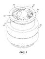
FIGURE 1 is a top perspective view of a turbo-molecular pump with a vacuum divider of the present invention mounted thereon. -
FIGURE 2 is a side plan view of an assembly formed from the vacuum divider ofFIGURE 1 seated between the turbo-molecular pump and a vacuum manifold. -
FIGURE 3 is a top plan view of the assembly ofFIGURE 2 having apertures in the vacuum divider formed by radially extending ribs and a bulkhead wall of the vacuum manifold following along the ribs. -
FIGURE 4 is a bottom perspective view of an embodiment of the vacuum divider ofFIGURE 1 having a flat bottom surface of the ribs. -
FIGURE 5 is a bottom perspective view of an embodiment of the vacuum divider ofFIGURE 1 utilizing a channel formed in the bottom surface of the ribs. -
FIGURE 6 is a top plan view of the assembly ofFIGURE 2 having apertures in the vacuum divider formed by bisecting ribs and a bulkhead wall of the vacuum manifold following along the ribs. -
FIGURE 7 is a graph illustrating the differential pumping the vacuum divider provides. -
FIGURE 8 is a diagrammatic view of a mass spectrometer system utilizing the vacuum assembly ofFIGURE 2 to separately evacuate an ion optics chamber and a mass analyzer chamber to different vacuum pressures. -
FIGURE 9 is a diagrammatic view, not to scale, of the closest distance between the vacuum divider and the rotor blades. - Referring to
FIGURES 1 and2 , the present invention combines avacuum divider 101 and avacuum manifold 201 with a turbo-molecular pump 105 in order to pump a differential vacuum between several vacuum chambers of a portion of avacuum system 100. This invention can dramatically decrease the cost of the vacuum system by allowing a single relatively inexpensive turbo-molecular pump, rather than several independent pumps, to be used to pump this differential vacuum. Moreover, this invention provides a system much more compact than the prior-art. - A
vacuum divider 101 is installed at ahigh vacuum inlet 103 of a turbo-molecular pump 105 in close proximity to the top ofrotor blades 107 of the turbo-molecular pump 105. The turbo-molecular pump 105 can be a Pfeiffer THM 261-020 YP, for example. -
FIGURE 2 is a side plan view of the portion of thevacuum system 100 with an addedvacuum manifold 201 attached to form avacuum assembly 200. Thevacuum divider 101 is seated between therotor blades 107 of turbo-molecular pump 105 and thevacuum manifold 201. In this embodiment, thevacuum divider 101 is shown installed at thehigh vacuum inlet 103, but in other embodiments it can be located up-stream or downstream from thehigh vacuum inlet 103 so long as it is located between therotor blades 107 of turbo-molecular pump 105 and thevacuum manifold 201 at a position relatively close to therotor blades 107. - The
vacuum divider 101 can be attached to the turbo-molecular pump 105 and thevacuum manifold 201 by a vacuum-tight seal. A vacuum-tight seal is defined as a seal where the leak rate into a vacuum chamber through the seal is small enough so as not to substantially affect the vacuum level within the vacuum chamber. Removable, vacuum-tight connections can be used to connect thevacuum divider 101 to the turbo-molecular pump 105 and/orvacuum manifold 201 using copper gasket / knife edge vacuum connections, o-ring connections, zero-clearance matching flat surfaces, overlapping joints, or other methods known in the art. Also, thevacuum divider 101 can be welded to either the turbo-molecular pump 105 or thevacuum manifold 201 or both of them. - In other embodiments the
vacuum divider 101 is integral with the turbo-molecular pump 105 or thevacuum manifold 201. For example, thevacuum divider 101 can be machined as a single piece with either the turbo-molecular pump 105 or thevacuum manifold 201 or both of them. This eliminates the need to fabricate thevacuum divider 101 as a separate part. -
FIGURE 3 is a top plan view of thevacuum assembly 200. In this embodiment of the invention afirst coupling aperture 301 and asecond coupling aperture 303 pass through thevacuum divider 101. Theseapertures vacuum divider 101 are formed by radially extendingribs ribs FIGURE 1 ) which covers the rotor shaft area at the top of the rotor stack. The apertures are additionally formed byaperture walls 311 through thevacuum divider 101. As can be seen from the figure, the first andsecond coupling apertures rib 305 crossing thevacuum divider 101 and also by therib 307 crossing thevacuum divider 101. - The
vacuum manifold 201 includes afirst vacuum chamber 313 and asecond vacuum chamber 315. Abulkhead wall 317 of thevacuum manifold 201 divides themanifold 201 into thefirst vacuum chamber 313 and thesecond vacuum chamber 315. Thebulkhead wall 317 follows and is sealed with a vacuum-tight seal to theribs ribs bulkhead wall 317 so that thefirst coupling aperture 301 andfirst vacuum chamber 313 form a first continuous space and thesecond coupling aperture 303 and thesecond vacuum chamber 315 form a second continuous space. Thus, thefirst coupling aperture 301 is fixed with a vacuum-tight seal to thefirst vacuum chamber 313 and thesecond coupling aperture 303 is fixed with a vacuum-tight seal to thesecond vacuum chamber 315. Also, thefirst coupling aperture 301 allows gas to pass from thefirst vacuum chamber 313 to the turbo-molecular pump 105 and thesecond coupling aperture 301 allows gas to pass from thesecond vacuum chamber 313 to the turbo-molecular pump 105. - A "pump inlet area allocation" is defined to be the area of each coupling aperture expressed as a percentage of the total area of all coupling apertures. The pump inlet area allocation of all apertures should add up to 100%. The
ribs central portion 309 are not considered in the calculation of pump inlet area. In this embodiment, the pump inlet area allocation can be set at 32% for thevacuum chamber vacuum chamber 315, for example. - In some embodiments the
vacuum manifold 201 includes afloor 318 with it's own coupling apertures passing through the floor and corresponding to the first andsecond coupling apertures vacuum divider 101. - The invention also encompasses embodiments having additional coupling apertures passing through the vacuum divider for allowing gas to pass from additional ones of the multiple vacuum chambers, through the
vacuum divider 101 and into the turbo-molecular pump 105. For example, thevacuum divider 101 can include three or more coupling apertures and thevacuum manifold 201 can include three or more vacuum chambers. Then each of the coupling apertures allows gas to pass from one of the vacuum chambers, through thevacuum divider 101 and into the turbo-molecular pump 105. The single turbo-molecular pump 105 can thereby pump three or more vacuum chambers of the vacuum system to produce three or more different vacuum pressures. -
FIGURE 4 is a bottom perspective view of an embodiment of thevacuum divider 101 having a flat rotor-blade-directedface 401 of theribs coupling apertures vacuum divider 101 is located between therotor blades 107 of the turbo-molecular pump 105 and thevacuum manifold 201 at a position relatively close to therotor blades 107. This distance relative to therotor blades 107 is preferably fixed so that the closest distance between thevacuum divider 101 and the rotor blades of the turbo-molecular pump 105 is less than 30% of aminimum width 403 of theribs gap distance 901 is shown schematically inFIGURE 9 as the closest distance 901 (note: the figure is not drawn to scale). For various shapedcoupling apertures minimum width 403 of the rotor-blade-directedface 401 separating the coupling apertures. Thus, in a more general embodiment, the position of thevacuum divider 101 is fixed relative to the turbo-molecular pump 105 so that theclosest distance 901 between the flat rotor-blade-directedface 401 and the rotor blades of the turbo-molecular pump 105 is less than 30% of theminimum width 403 of the rotor-blade-directedface 401 separating the coupling apertures. - In one embodiment the
vacuum divider 101 ofFIGURE 4 is inserted into thehigh vacuum inlet 103 of the turbo-molecular pump 105 ofFIGURE 2 , where the turbo-molecular pump can be the Edwards model EXT255H. The divider can then be mated with a matching flat surface on thevacuum manifold 201. O-rings can be used to seal the turbo-molecular pump flange and thevacuum divider 101 to thevacuum manifold 201. Thus the twodistinct vacuum chambers -
FIGURE 5 is a bottom perspective view of another embodiment of thevacuum divider 101 having a rotor-blade-directedface 503 of theribs coupling apertures FIGURE 4 , but with the addition of achannel 501 formed in the rotor-blade-directedface 503. The purpose of thechannel 501 of this embodiment of thevacuum divider 101 is to create an intermediate vacuum region between the twovacuum chambers vacuum manifold 201. This decreases the amount of gas that can pass between theapertures vacuum chambers -
FIGURE 6 is a top plan view of avariation 600 of thevacuum assembly 200 ofFIGURE 3 . In thisembodiment coupling apertures vacuum divider 621 are formed by bisectingribs central portion 609, and abulkhead wall 617 of thevacuum manifold 619 follows along theribs coupling apertures vacuum chambers vacuum assembly 200 ofFIGURE 3 . In this embodiment, the pump inlet area allocation can be set at 60% for thevacuum chamber 613 and 40% for thevacuum chamber 615, for example. - Experimental prototypes of the
vacuum divider 101 were built and tested. The vacuum dividers were inserted into the high vacuum inlet of an Edwards EXT255H turbo-molecular pump. With a vacuum divider installed, the turbo-molecular pump was mounted to a vacuum manifold. The vacuum divider used for the tests had theradially extending ribs FIGURE 3 and thebulkhead wall 317 following along the ribs. Ion gauges were used to measure the pressure in each of the twovacuum chambers - A precision leak valve was added to the
vacuum chamber 313 to allow for an adjustable gas load. Thevacuum chamber 315 had no external gas load. Thus, during the tests, thevacuum chamber 313 was at a higher pressure than thevacuum chamber 315. - A "Differential Pumping Ratio" ("DPR"), is defined as the pressure in the
vacuum chamber 313 divided by the pressure in thevacuum chamber 315. During testing of the prototypes, four different parameters were varied to find their effect on the DPR: - 1. The vacuum divider design of
FIGURE 4 (flat rotor-blade-directedface 401 of theribs 305, 307) and the divider design ofFIGURE 5 (channel 501 cut into the rotor-blade-directed face 503) were used. - 2. The closest distances between both of the rotor-blade-directed
faces rotor blades 107 were set to both 0.75mm or 1.50mm. - 3. The pump inlet area allocation was set at 68% for the
vacuum chamber vacuum chamber 315 and also set at 32% for thevacuum chamber vacuum chamber 315. - 4. The gas load was varied by changing the precision leak valve settings.
-
FIGURE 7 is a graph illustrating DPR (vertical axis) as a function of the pressure of the vacuum chamber 313 (horizontal axis) for an optimum combination of the parameters. The divider design ofFIGURE 5 having thechannel 501 was used. The distance between the rotor-blade-directedface 503 and therotor blades 107 was set to 0.75mm. The pump inlet area allocation was set at 32% for thevacuum chamber vacuum chamber 315. The pressure of thevacuum chamber 313 was increased by opening the precision leak valve and at each data point the DPR was calculated. - Previous to the testing of the present invention, the expectation would be to obtain a DPR of between 3 and 5. However, it was found that the present invention easily produces a DPR of more than 5, or even a DPR of more than 10. Moreover, for this particular configuration utilizing the
vacuum divider 101 of the present invention, and when the gas load was increased to the point where the pressure in thevacuum chamber 313 was approximately 1.0 x 10⁻⁴ Torr, the results showed that the vacuum divider worked together with the turbo-molecular pump and vacuum manifold in an unexpected and fruitful manner to produce an amazing DPR of 17! This is about a quadruple improvement over what would previously have been expected. - Some general observations of the effects of the different parameters on the DPR are now explained.
- The divider design of
FIGURE 5 with thechannel 501 formed in the rotor-blade-directedface 503 was found to produce a 6% to 14% improvement in the DPR compared to that of the divider ofFIGURE 4 having the flat rotor-blade-directedface 401. - It was expected that smaller gap distances between the vacuum divider and the rotor blades would result in an improved DPR. This was indeed shown in the experiments, but the effect was relatively small. Changing the gap distance from 0.75mm to 1.50mm resulted in only a 7% reduction in the DPR. In general it can be desirable to set the gap distance at 1.50mm or less.
- On the other hand, the pump inlet area allocation had a significant effect on the DPR. As mentioned above, the test setup was configured in two ways with regard to the pump inlet area allocation. The pump inlet area allocation was set at 68% for the
vacuum chamber vacuum chamber 315 and also set at 32% for thevacuum chamber vacuum chamber 315. The DPR more than doubled when the pump inlet area allocation was switched from 68% for thevacuum chamber vacuum chamber 315 to 32% for thevacuum chamber vacuum chamber 315. - The
vacuum divider 101 of the present invention can be used with a turbo-molecular pump, such as the Pfeiffer TMH 262-020 YP, to provide differential pumping for an Agilent Technologies 6110 Single quad LCMS for example.FIGURE 8 is a diagrammatic view of amass spectrometer system 801 utilizing the portion of thevacuum assembly 200 ofFIGURE 2 to separately evacuate anion optics chamber 803 and amass analyzer chamber 805 to different vacuum pressures. Theion optics chamber 803 can contain an ion guide, a collision cell, or other ion optics elements. Theion optics chamber 803 can be evacuated through thefirst vacuum chamber 313 and themass analyzer chamber 805 can be evacuated through thesecond vacuum chamber 315. - In another embodiment, the relative sizes of the
coupling apertures coupling apertures vacuum chambers ion optics chamber 803 andmass analyzer chamber 805 can be fine tuned. - By adjusting the various parameters, such as the pump inlet area allocation, the measured DPRs of the
vacuum chambers - In the present invention the gas referred to can be air or other gasses.
- The vacuum divider can be made from aluminum, stainless steel, high performance engineering plastic or other known materials.
- The present invention may be embodied in other forms without departing from its spirit and scope. The embodiments described above are therefore illustrative and not restrictive, since the scope of the invention is determined by the appended claims rather then by the foregoing description, and all changes that fall within the meaning and range of equivalency of the claims are to be embraced within their scope.
Claims (10)
- A vacuum divider (101) for positioning between rotor blades (107) of a turbo-molecular pump (105) and a vacuum manifold (201) formed from multiple vacuum chambers (313, 315) comprising:a first coupling aperture (301) passing through the vacuum divider (101) for allowing gas to pass from a first of the multiple vacuum chambers (313) to the turbo-molecular pump (105), and a second coupling aperture (303) passing through the vacuum divider (101) for allowing gas to pass from a second of the multiple vacuum chambers (315) to the turbo-molecular pump (105).
- The vacuum divider of Claim 1, wherein the vacuum divider has a rotor-blade-directed face (401) and is fixed relative to the turbo-molecular pump so that the closest distance between the face and the rotor blades of the turbo-molecular pump is less than 30% of a minimum width of the rotor-blade-directed face separating the coupling apertures.
- The vacuum divider of Claim 1, wherein the vacuum divider has a rotor-blade-directed face (401) and wherein a channel (501) is formed in the rotor-blade-directed face.
- The vacuum divider of Claim 1, wherein the vacuum divider has a rotor-blade-directed face (401) and wherein the rotor-blade directed face is a flat surface (401).
- The vacuum divider of Claim 1, further comprising additional coupling apertures passing through the vacuum divider for allowing gas to pass from additional ones of the multiple vacuum chambers to the turbo-molecular pump (105).
- The vacuum divider of Claim 1, wherein each of the coupling apertures (301, 303) is fixed with a vacuum-tight seal to one of the vacuum chambers (313, 315).
- The vacuum divider of Claim 1, wherein:the first and second coupling apertures (301, 303) are separated by a rib (305, 307) crossing the vacuum divider (101);the first and second of the multiple vacuum chambers are separated by a bulkhead wall (617); andthe rib (305, 307) is disposed for alignment with the bulkhead wall (617) so that the first coupling aperture (301) and first vacuum chamber form a first continuous space and the second coupling aperture (303) and second vacuum chamber form a second continuous space.
- The vacuum divider of Claim 7, wherein the rib (305, 307) is disposed for vacuum-tight connection with the bulkhead wall (617).
- A vacuum system (100) incorporating the vacuum divider of Claim 1 wherein there is a differential vacuum between the vacuum chambers connected through the apertures of the divider to the turbo-molecular pump (105).
- The vacuum divider of Claim 1, wherein the relative sizes of the apertures (301, 303) are adjustable.
Applications Claiming Priority (1)
| Application Number | Priority Date | Filing Date | Title |
|---|---|---|---|
| US11/749,083 US8147222B2 (en) | 2007-05-15 | 2007-05-15 | Vacuum divider for differential pumping of a vacuum system |
Publications (2)
| Publication Number | Publication Date |
|---|---|
| EP1992822A1 true EP1992822A1 (en) | 2008-11-19 |
| EP1992822B1 EP1992822B1 (en) | 2010-06-16 |
Family
ID=39687035
Family Applications (1)
| Application Number | Title | Priority Date | Filing Date |
|---|---|---|---|
| EP20080103846 Active EP1992822B1 (en) | 2007-05-15 | 2008-05-07 | Vacuum divider for differential pumping of a vacuum system |
Country Status (4)
| Country | Link |
|---|---|
| US (1) | US8147222B2 (en) |
| EP (1) | EP1992822B1 (en) |
| CN (1) | CN101307771B (en) |
| DE (1) | DE602008001528D1 (en) |
Cited By (2)
| Publication number | Priority date | Publication date | Assignee | Title |
|---|---|---|---|---|
| EP2153070A1 (en) * | 2007-06-11 | 2010-02-17 | Oerlikon Leybold Vacuum GmbH | Turbomolecular pump |
| EP2039941A3 (en) * | 2007-09-20 | 2016-06-01 | Pfeiffer Vacuum Gmbh | Vacuum pump |
Families Citing this family (6)
| Publication number | Priority date | Publication date | Assignee | Title |
|---|---|---|---|---|
| GB2498816A (en) | 2012-01-27 | 2013-07-31 | Edwards Ltd | Vacuum pump |
| US10037869B2 (en) | 2013-08-13 | 2018-07-31 | Lam Research Corporation | Plasma processing devices having multi-port valve assemblies |
| EP3051139B1 (en) * | 2015-01-28 | 2018-12-12 | Pfeiffer Vacuum Gmbh | Vacuum pump |
| KR102499085B1 (en) * | 2016-05-04 | 2023-02-10 | 삼성전자주식회사 | Vacuum pump |
| GB201808912D0 (en) * | 2018-05-31 | 2018-07-18 | Micromass Ltd | Bench-top time of flight mass spectrometer |
| JP7327229B2 (en) * | 2020-03-18 | 2023-08-16 | 株式会社島津製作所 | Protective nets, turbomolecular pumps and mass spectrometers |
Citations (5)
| Publication number | Priority date | Publication date | Assignee | Title |
|---|---|---|---|---|
| US4787829A (en) | 1986-05-08 | 1988-11-29 | Mitsubishi Denki Kabushiki Kaisha | Turbomolecular pump |
| EP1030062A2 (en) * | 1999-02-19 | 2000-08-23 | Ebara Corporation | Turbo-molecular pump |
| EP1061262A2 (en) * | 1999-06-14 | 2000-12-20 | Ebara Corporation | Turbo-molecular pump |
| US20050106005A1 (en) | 2002-03-13 | 2005-05-19 | Paul Mokler | Turbo molecular high-vacuum pump with a circular intake area |
| EP1626179A2 (en) | 2004-08-10 | 2006-02-15 | Pfeiffer Vacuum GmbH | Vacuum pump |
Family Cites Families (11)
| Publication number | Priority date | Publication date | Assignee | Title |
|---|---|---|---|---|
| US4581533A (en) * | 1984-05-15 | 1986-04-08 | Nicolet Instrument Corporation | Mass spectrometer and method |
| CN1037195A (en) * | 1988-04-29 | 1989-11-15 | 瓦拉里·波里斯维奇·肖鲁克夫 | Molecular vacuum pump |
| US5358373A (en) * | 1992-04-29 | 1994-10-25 | Varian Associates, Inc. | High performance turbomolecular vacuum pumps |
| US5733104A (en) * | 1992-12-24 | 1998-03-31 | Balzers-Pfeiffer Gmbh | Vacuum pump system |
| US5565679A (en) * | 1993-05-11 | 1996-10-15 | Mds Health Group Limited | Method and apparatus for plasma mass analysis with reduced space charge effects |
| US6142163A (en) * | 1996-03-29 | 2000-11-07 | Lam Research Corporation | Method and apparatus for pressure control in vacuum processors |
| FR2761776B1 (en) * | 1997-04-03 | 1999-07-23 | Alsthom Cge Alcatel | GAS LEAK DETECTOR |
| US6926493B1 (en) * | 1997-06-27 | 2005-08-09 | Ebara Corporation | Turbo-molecular pump |
| US6589009B1 (en) * | 1997-06-27 | 2003-07-08 | Ebara Corporation | Turbo-molecular pump |
| JP2004014177A (en) * | 2002-06-04 | 2004-01-15 | Shimadzu Corp | Mass spectrometer |
| DE10302764A1 (en) * | 2003-01-24 | 2004-07-29 | Pfeiffer Vacuum Gmbh | Vacuum pumping system |
-
2007
- 2007-05-15 US US11/749,083 patent/US8147222B2/en active Active
-
2008
- 2008-05-07 DE DE200860001528 patent/DE602008001528D1/en active Active
- 2008-05-07 EP EP20080103846 patent/EP1992822B1/en active Active
- 2008-05-15 CN CN2008100975913A patent/CN101307771B/en active Active
Patent Citations (5)
| Publication number | Priority date | Publication date | Assignee | Title |
|---|---|---|---|---|
| US4787829A (en) | 1986-05-08 | 1988-11-29 | Mitsubishi Denki Kabushiki Kaisha | Turbomolecular pump |
| EP1030062A2 (en) * | 1999-02-19 | 2000-08-23 | Ebara Corporation | Turbo-molecular pump |
| EP1061262A2 (en) * | 1999-06-14 | 2000-12-20 | Ebara Corporation | Turbo-molecular pump |
| US20050106005A1 (en) | 2002-03-13 | 2005-05-19 | Paul Mokler | Turbo molecular high-vacuum pump with a circular intake area |
| EP1626179A2 (en) | 2004-08-10 | 2006-02-15 | Pfeiffer Vacuum GmbH | Vacuum pump |
Cited By (2)
| Publication number | Priority date | Publication date | Assignee | Title |
|---|---|---|---|---|
| EP2153070A1 (en) * | 2007-06-11 | 2010-02-17 | Oerlikon Leybold Vacuum GmbH | Turbomolecular pump |
| EP2039941A3 (en) * | 2007-09-20 | 2016-06-01 | Pfeiffer Vacuum Gmbh | Vacuum pump |
Also Published As
| Publication number | Publication date |
|---|---|
| CN101307771A (en) | 2008-11-19 |
| EP1992822B1 (en) | 2010-06-16 |
| DE602008001528D1 (en) | 2010-07-29 |
| US8147222B2 (en) | 2012-04-03 |
| CN101307771B (en) | 2012-01-04 |
| US20080283125A1 (en) | 2008-11-20 |
Similar Documents
| Publication | Publication Date | Title |
|---|---|---|
| EP1992822B1 (en) | Vacuum divider for differential pumping of a vacuum system | |
| EP2481077B1 (en) | Mass spectrometer system | |
| US8757987B2 (en) | Vacuum pump for differentially pumping multiple chambers | |
| KR101127124B1 (en) | Compressor wheel housing | |
| US6709228B2 (en) | Vacuum pumps | |
| CN102333961B (en) | Impeller of centrifugal compressor | |
| US9627189B2 (en) | Vacuum system | |
| US10895266B2 (en) | Centrifugal blower assembly and method for assembling the same | |
| JP5574951B2 (en) | Centrifugal compressor impeller | |
| EP3516275B1 (en) | Valve gate within a venturi gap of a venturi device for producing vacuum | |
| US20170067487A1 (en) | Turbomachine blade | |
| EP1249613B1 (en) | Turbine pump with a stator stage integrated with a spacer ring | |
| US6779968B1 (en) | Side channel compressor | |
| KR101174270B1 (en) | Measurement System and Methods of Pumping Speed of Vacuum Pumps Using Sonic Nozzles | |
| KR100347637B1 (en) | Gas analysis and leak detection device | |
| US5456575A (en) | Non-centric improved pumping stage for turbomolecular pumps | |
| US20100187415A1 (en) | Turbomolecular pump | |
| US11053951B2 (en) | Centrifugal compressor impeller and compressor comprising said impeller | |
| US20150330389A1 (en) | Vane pump | |
| CN112362719B (en) | Airflow flow control device and ion mobility spectrometer | |
| KR20120030523A (en) | Method of converting liquid ring pumps having sealing liquid vents | |
| US20080056886A1 (en) | Vacuum pumps with improved pumping channel cross sections | |
| WO2021016321A1 (en) | Fluid systems and methods that address flow separation | |
| US12546323B2 (en) | Compressor with curved passage | |
| EP4111058B1 (en) | Flange for a vacuum apparatus |
Legal Events
| Date | Code | Title | Description |
|---|---|---|---|
| PUAI | Public reference made under article 153(3) epc to a published international application that has entered the european phase |
Free format text: ORIGINAL CODE: 0009012 |
|
| AK | Designated contracting states |
Kind code of ref document: A1 Designated state(s): AT BE BG CH CY CZ DE DK EE ES FI FR GB GR HR HU IE IS IT LI LT LU LV MC MT NL NO PL PT RO SE SI SK TR |
|
| AX | Request for extension of the european patent |
Extension state: AL BA MK RS |
|
| 17P | Request for examination filed |
Effective date: 20090519 |
|
| 17Q | First examination report despatched |
Effective date: 20090617 |
|
| AKX | Designation fees paid |
Designated state(s): DE GB |
|
| RAP1 | Party data changed (applicant data changed or rights of an application transferred) |
Owner name: AGILENT TECHNOLOGIES, INC. |
|
| GRAP | Despatch of communication of intention to grant a patent |
Free format text: ORIGINAL CODE: EPIDOSNIGR1 |
|
| GRAS | Grant fee paid |
Free format text: ORIGINAL CODE: EPIDOSNIGR3 |
|
| GRAA | (expected) grant |
Free format text: ORIGINAL CODE: 0009210 |
|
| AK | Designated contracting states |
Kind code of ref document: B1 Designated state(s): DE GB |
|
| REF | Corresponds to: |
Ref document number: 602008001528 Country of ref document: DE Date of ref document: 20100729 Kind code of ref document: P |
|
| PLBE | No opposition filed within time limit |
Free format text: ORIGINAL CODE: 0009261 |
|
| STAA | Information on the status of an ep patent application or granted ep patent |
Free format text: STATUS: NO OPPOSITION FILED WITHIN TIME LIMIT |
|
| 26N | No opposition filed |
Effective date: 20110317 |
|
| REG | Reference to a national code |
Ref country code: DE Ref legal event code: R097 Ref document number: 602008001528 Country of ref document: DE Effective date: 20110316 |
|
| PGFP | Annual fee paid to national office [announced via postgrant information from national office to epo] |
Ref country code: DE Payment date: 20250402 Year of fee payment: 18 |
|
| PGFP | Annual fee paid to national office [announced via postgrant information from national office to epo] |
Ref country code: GB Payment date: 20250401 Year of fee payment: 18 |