EP1995441A2 - Fluted chevron exhaust nozzle - Google Patents
Fluted chevron exhaust nozzle Download PDFInfo
- Publication number
- EP1995441A2 EP1995441A2 EP08152999A EP08152999A EP1995441A2 EP 1995441 A2 EP1995441 A2 EP 1995441A2 EP 08152999 A EP08152999 A EP 08152999A EP 08152999 A EP08152999 A EP 08152999A EP 1995441 A2 EP1995441 A2 EP 1995441A2
- Authority
- EP
- European Patent Office
- Prior art keywords
- nozzle
- chevrons
- ridges
- slots
- circumferentially
- Prior art date
- Legal status (The legal status is an assumption and is not a legal conclusion. Google has not performed a legal analysis and makes no representation as to the accuracy of the status listed.)
- Granted
Links
- WYTGDNHDOZPMIW-RCBQFDQVSA-N alstonine Natural products C1=CC2=C3C=CC=CC3=NC2=C2N1C[C@H]1[C@H](C)OC=C(C(=O)OC)[C@H]1C2 WYTGDNHDOZPMIW-RCBQFDQVSA-N 0.000 claims abstract description 25
- 230000000694 effects Effects 0.000 claims description 5
- 241000510122 Lasmigona costata Species 0.000 abstract description 2
- 239000007789 gas Substances 0.000 description 13
- 239000000203 mixture Substances 0.000 description 7
- 239000000567 combustion gas Substances 0.000 description 6
- 238000011144 upstream manufacturing Methods 0.000 description 6
- 230000008901 benefit Effects 0.000 description 3
- 238000002156 mixing Methods 0.000 description 3
- 230000004323 axial length Effects 0.000 description 2
- 238000010276 construction Methods 0.000 description 2
- 230000007423 decrease Effects 0.000 description 2
- 239000000284 extract Substances 0.000 description 2
- 239000000446 fuel Substances 0.000 description 2
- 230000001965 increasing effect Effects 0.000 description 2
- 239000002184 metal Substances 0.000 description 2
- 230000004048 modification Effects 0.000 description 2
- 238000012986 modification Methods 0.000 description 2
- 230000002411 adverse Effects 0.000 description 1
- 230000033228 biological regulation Effects 0.000 description 1
- 230000005465 channeling Effects 0.000 description 1
- 238000002485 combustion reaction Methods 0.000 description 1
- 230000000295 complement effect Effects 0.000 description 1
- 150000001875 compounds Chemical class 0.000 description 1
- 230000003247 decreasing effect Effects 0.000 description 1
- 230000002708 enhancing effect Effects 0.000 description 1
- 230000006872 improvement Effects 0.000 description 1
- 238000002955 isolation Methods 0.000 description 1
- 230000009467 reduction Effects 0.000 description 1
- 230000001629 suppression Effects 0.000 description 1
- 230000007704 transition Effects 0.000 description 1
Images


Classifications
-
- F—MECHANICAL ENGINEERING; LIGHTING; HEATING; WEAPONS; BLASTING
- F02—COMBUSTION ENGINES; HOT-GAS OR COMBUSTION-PRODUCT ENGINE PLANTS
- F02K—JET-PROPULSION PLANTS
- F02K1/00—Plants characterised by the form or arrangement of the jet pipe or nozzle; Jet pipes or nozzles peculiar thereto
- F02K1/46—Nozzles having means for adding air to the jet or for augmenting the mixing region between the jet and the ambient air, e.g. for silencing
- F02K1/48—Corrugated nozzles
-
- F—MECHANICAL ENGINEERING; LIGHTING; HEATING; WEAPONS; BLASTING
- F02—COMBUSTION ENGINES; HOT-GAS OR COMBUSTION-PRODUCT ENGINE PLANTS
- F02K—JET-PROPULSION PLANTS
- F02K1/00—Plants characterised by the form or arrangement of the jet pipe or nozzle; Jet pipes or nozzles peculiar thereto
- F02K1/38—Introducing air inside the jet
- F02K1/386—Introducing air inside the jet mixing devices in the jet pipe, e.g. for mixing primary and secondary flow
-
- F—MECHANICAL ENGINEERING; LIGHTING; HEATING; WEAPONS; BLASTING
- F05—INDEXING SCHEMES RELATING TO ENGINES OR PUMPS IN VARIOUS SUBCLASSES OF CLASSES F01-F04
- F05D—INDEXING SCHEME FOR ASPECTS RELATING TO NON-POSITIVE-DISPLACEMENT MACHINES OR ENGINES, GAS-TURBINES OR JET-PROPULSION PLANTS
- F05D2250/00—Geometry
- F05D2250/10—Two-dimensional
- F05D2250/18—Two-dimensional patterned
- F05D2250/183—Two-dimensional patterned zigzag
-
- F—MECHANICAL ENGINEERING; LIGHTING; HEATING; WEAPONS; BLASTING
- F05—INDEXING SCHEMES RELATING TO ENGINES OR PUMPS IN VARIOUS SUBCLASSES OF CLASSES F01-F04
- F05D—INDEXING SCHEME FOR ASPECTS RELATING TO NON-POSITIVE-DISPLACEMENT MACHINES OR ENGINES, GAS-TURBINES OR JET-PROPULSION PLANTS
- F05D2250/00—Geometry
- F05D2250/10—Two-dimensional
- F05D2250/18—Two-dimensional patterned
- F05D2250/184—Two-dimensional patterned sinusoidal
-
- Y—GENERAL TAGGING OF NEW TECHNOLOGICAL DEVELOPMENTS; GENERAL TAGGING OF CROSS-SECTIONAL TECHNOLOGIES SPANNING OVER SEVERAL SECTIONS OF THE IPC; TECHNICAL SUBJECTS COVERED BY FORMER USPC CROSS-REFERENCE ART COLLECTIONS [XRACs] AND DIGESTS
- Y02—TECHNOLOGIES OR APPLICATIONS FOR MITIGATION OR ADAPTATION AGAINST CLIMATE CHANGE
- Y02T—CLIMATE CHANGE MITIGATION TECHNOLOGIES RELATED TO TRANSPORTATION
- Y02T50/00—Aeronautics or air transport
- Y02T50/60—Efficient propulsion technologies, e.g. for aircraft
Definitions
- the present invention relates generally to gas turbine engines, and, more specifically, to exhaust nozzles therein.
- HPT high pressure turbine
- LPT low pressure turbine
- a substantial portion of the air pressurized by the fan is used for providing propulsion thrust for powering an aircraft in flight.
- a portion of the fan air is further pressurized in the compressor for generating the combustion gases which are also discharged from the engine to provide additional thrust.
- the engine may include two separate exhaust nozzles, one for the fan air and one for core exhaust, which both discharge their exhaust flows together into the ambient external airstream for propelling the aircraft during flight.
- the high velocity engine exhaust flow mixes with the ambient airflow and generates considerable noise during aircraft takeoff and climb from an airport. Government regulations limit noise levels, and are a significant design objective especially for more powerful aircraft engines.
- a modern noise attenuation exhaust nozzle is disclosed is U.S. Patent 6,360,528 assigned to the present assignee.
- the chevron nozzle in this patent has a serpentine triangular trailing edge and separates internal and external flowstreams.
- the chevron nozzle is a relatively thin, single-ply sheet metal shell which permits the relatively slow velocity external flow to mix with the higher velocity internal core flow for substantially reducing the velocity thereof, and correspondingly reducing noise.
- the chevron nozzle is being developed specifically for reducing noise in subsonic commercial aircraft engines which require maximum efficiency of operation, yet such noise reduction does not significantly compromise engine efficiency due to the simple and lightweight chevron nozzle.
- a convergent-divergent (CD) exhaust nozzle which is typically variable, is typically used for supersonic engines with and without afterburners or combustion augmenters.
- Subsonic commercial aircraft typically have turbofan engines with converging exhaust nozzles operating up to about a nozzle pressure ratio of 4.
- Supersonic turbofan engines are typically designed with higher nozzle pressure ratios exceeding 4, and utilize the CD nozzle for optimizing performance.
- the CD nozzle is inherently more complex than the simpler converging subsonic nozzle, and has a greater need for noise attenuation due to the increased velocity of the exhaust flow.
- a gas turbine engine exhaust nozzle includes a fluted shell terminating in a row of chevrons.
- the nozzle is radially serpentine circumferentially around the shells and has a circumferentially serpentine trailing edge.
- FIG. 1 Illustrated schematically in Figure 1 is an exemplary turbofan gas turbine aircraft engine 10 configured for powering an aircraft (not shown) in flight to supersonic flight speeds.
- the engine is axisymmetric about a longitudinal or axial centerline axis 12.
- the engine 10 may have any conventional configuration including a multistage axial compressor for pressurizing air 14 which is mixed with fuel and ignited in a combustor for generating hot combustion gases 16.
- An HPT extracts energy from the combustion gases to power the compressor, and a LPT extracts energy from the combustion gases to power an upstream fan.
- the engine has various internal and external casings which define internal flow passages and bypass ducts for separately channeling the pressurized air and core gases therethrough.
- the engine may also include a fan-on-blade (FLADE) configuration which pressurizes the air in two separate annular flowpaths from a common row of fan blades.
- FLADE fan-on-blade
- the pressurized air and core gases are typically discharged from the aft end of the engine in concentric streams either inverted or not depending upon the specific design of the engine.
- the exhaust flows 14,16 from the engine 10 create noise when discharged into the atmosphere during aircraft propulsion.
- the engine includes at its aft end outer and inner annular acoustic exhaust nozzles 18,20 surrounding a centerbody or plug 22 coaxially around the common centerline axis 12.
- the core combustion gases 16 are discharged through the outer nozzle 18, while the pressurized fan air 14 is discharged through the inner nozzle 20.
- the fan air would be discharged through the outer nozzle 18, and the core gases 16 discharged through the inner nozzle 20.
- the freestream airflow 14 flows outside the nozzles as the engine propels the aircraft during flight operation.
- the two nozzles 18,20 initially illustrated in Figure 1 are specifically configured for improving mixing between the internal and external flowstreams for reducing maximum flow velocity and thereby attenuating or reducing noise during operation.
- the outer acoustic nozzle 18 is illustrated in a first exemplary embodiment in Figure 2-4 .
- the exhaust nozzle 18 includes concentric outer and inner shells or annular walls 24,26 extending coaxially about the common centerline axis 12 illustrated in Figure 1 between forward and aft ends thereof.
- the forward end of the nozzle is suitably mounted to an aft frame in the engine in a conventional manner.
- the two shells 24,26 may be formed of thin sheet metal and are spaced radially apart from each other, and are supported by internal ribs or gussets as required for aerodynamic flow control. Over their axially aft portions, the two shells converge radially together to a row of triangular chevrons 28 which define a circumferentially serpentine trailing edge 30 of the nozzle.
- Figure 1 shows the outer row of identical chevrons 28 in uniform repetition around the nozzle circumference, with the trailing edge 30 thereof varying in axial position along the axial length L of the chevrons to define the circumferentially serpentine configuration thereof.
- the chevrons 28 are spaced circumferentially apart by respective axially diverging slots 32 which complement the converging chevrons in the uniform row thereof.
- each chevron 28 is triangular in the aft direction and converges in lateral or circumferential width W axially between its forward or upstream base 34 and its aft or downstream apex 36 along the serpentine trailing edge 30 on opposite lateral sides or edges of each chevron.
- each of the slots 32 is also triangular between two adjacent chevrons 28 and diverges axially aft in width from a root notch 38 in the same axial plane as the chevron bases 34.
- the slots diverge in the aft direction and terminate at the common aft plane of the chevron apexes 36.
- the chevrons are additionally radially serpentine circumferentially around the shells in addition to being circumferentially serpentine along the common trailing edge 30 thereof.
- Each chevron 28 therefore decreases in radial thickness T both axially and circumferentially to the thin trailing edge 30 which laterally bounds each chevron as illustrated in Figure 4 .
- each chevron includes a central crown or ridge 40 extending upstream or forwardly from the apex 36 symmetrically or equidistantly between the two side edges 30 thereof.
- the central ridge 40 continues forwardly past the chevron base 34 along the two shells to the forward portion thereof.
- the central ridges 40 corresponding with the chevrons 28 alternate with circumferentially adjacent corresponding valleys or flutes 42 extending axially forward from the slots 32 at their forwardmost notches 38.
- the ridges 40 extend axially forwardly from the corresponding chevron apexes 36, and the cooperating flutes 42 extend axially forwardly in parallel therewith from the corresponding slot notches 38 to effect the radially serpentine configuration circumferentially around the shells.
- Figure 2 illustrates the double wall configuration of the exhaust nozzle 18 and its increasing thickness forward from the aft trailing edge, and then its decreasing thickness over its forward portion as desired.
- the chevrons 28 are introduced into the double wall nozzle, the base ends thereof at the slot notches 38 have a substantial radial thickness greater than the uniform thickness of the conventional single-ply subsonic chevron nozzle disclosed in the Background.
- the two shells 24,26 may converge together in radial thickness both axially and circumferentially to the serpentine chevron trailing edge 30 around the corresponding diverging slots 32.
- each chevron 28 has a thin trailing edge of minimum thickness along both side edges from the aft apex 36 to the root notches 38 and then blends aerodynamically both circumferentially to the central ridge 40 as well as axially aft along the flutes 42 between the ridges as the two shells increase in radial spacing in the aft direction.
- the double wall chevron nozzle therefore includes the original circumferentially serpentine trailing edge 30 around the perimeter in addition to the radially serpentine configuration introduced by the elevated ridges 40 and intervening recessed flutes 42 which aerodynamically blend the flow surfaces of the nozzle along the perimeters of each chevron and intervening diverging slot.
- a significant improvement in aerodynamic efficiency is thusly created by the duplex or double serpentine chevron nozzle to smoothly blend both external and internal flowstreams without the introduction of aft facing bluff bodies and associated aerodynamic loss therefrom.
- Figure 1 illustrates two embodiments of the exhaust nozzles 18,20 in a common aircraft engine application.
- the chevron nozzles replace conventional conical exhaust nozzles and may be used individually for either the outer nozzle or the inner nozzle, with the other nozzle remaining the conventional conical nozzle without chevrons if desired.
- the inner shell 26 is circular in section with a constant radius R from the centerline axis at each axial section, and the outer shell 24 is radially serpentine and varies in radial position to include the axial ridges 40 and intervening axial flutes 42.
- the inner shell 26 is cylindrical or conical as desired, and includes a smooth circular inner surface that defines an internal exhaust duct 44 which terminates in an annular outlet 46 at the chevrons 28.
- the outer shell 24 includes the external ridges 40 extending axially aft along the outer surface thereof. And, the external flutes 42 extend axially aft between the external ridges 40 to the respective diverging slots 32 between the chevrons.
- the inner shell 26 has a cylindrical configuration over its aft portion, with the outer shell 24 converging aft thereover. Accordingly, the external flutes 42 preferably begin at the forward end of the nozzle and then increase in radial depth axially aft along the ridges 40 to the slots 32.
- the flutes 42 taper and blend at their forward ends into the uniform conical surface of the outer shell at its forward end, and also blend and taper to the diverging slots 32 at the aft ends thereof.
- Figures 5-7 illustrate the inner nozzle 20 in a second embodiment in which like reference numerals identify like parts, but differently located.
- the outer shell 24 in this embodiment is smoothly conical and has circular cross sections, whereas the inner shell 26 is radially serpentine to cooperate with the circumferentially serpentine trailing edge 30 of the row of chevrons 28.
- the outer shell 24 in this embodiment has a smooth circular outer surface over which the external flow may smoothly travel.
- the inner shell 26 in this embodiment varies circumferentially in radial position to include the internal ridges 40 extending axially aft along the inner surface thereof.
- the cooperating internal flutes 42 extend axially aft between the internal ridges 40 to the corresponding diverging slots 32 to define another exhaust duct 48 terminating in another outlet 50 at the chevrons 28.
- the two exhaust nozzles 18,20 illustrated in Figures 1-7 are used in combination to define the outer exhaust duct 44 and outer nozzle outlet 46 surrounding the inner exhaust duct 48 and inner exhaust outlet 50.
- the outer duct 44 carries the inverted core gases 16, with ambient airflow 14 being channeled outside the outer duct.
- the inner duct 48 carries the inverted fan air 14, with the core flow 16 being discharged outside the inner nozzle 20.
- the externally serpentine nozzle 18 may be used alone, and the internally serpentine nozzle 20 may also be used alone where aerodynamic performance may be enhanced thereby.
- the internal flutes 42 have substantially constant radial depth axially aft along the corresponding ridges 40 over most of the aft portion of the exhaust nozzle to the aft slots 32.
- the ridges 40 and flutes 42 may be introduced in either the outer or inner shells in various embodiments including the two embodiments illustrated in Figures 2 and 6 in contrast.
- FIGS 8 and 9 illustrate another embodiment of an exhaust nozzle, designated 52, which is generally similar to the internal serpentine nozzle 20 illustrated in Figures 5-7 .
- Like reference numerals indicate like features.
- the two nozzles 52 and 20 are generally similar to each other in configuration except that the internal flutes 42 in Figure 8 increase in radial depth axially aft along the corresponding ridges 40 to the corresponding diverging slots 32. This permits, for example, different flow area control of the exhaust duct 44 in accordance with the specific requirements of the gas turbine engine.
- the inner shell 26 illustrated in Figure 8 has a generally cylindrical profile with the corresponding internal ridges 40 extending axially therealong.
- the internal flutes 42 commence at the relatively thick forward end of the nozzle and increase in depth and radius aft where they meet the diverging slots.
- FIGS 10 and 11 illustrate yet another embodiment of an exhaust nozzle designated 54, which is a variation of the external serpentine nozzle 18 illustrated in Figures 1-4 .
- Like reference numerals indicate like features.
- the external flutes 42 have a substantially constant radial depth axially aft along the ridges 40 to the diverging slots 32 over most of the axial length of the nozzle.
- the ridges and flutes may commence well upstream of the converging portion of the nozzle and continue with uniform height and depth over the converging aft portion of the nozzle to the chevrons 28.
- This configuration may be used to advantage to control aerodynamic performance of the external flow field outside the nozzle 54 as it blends and mixes with the internal flowstream discharged from the exhaust duct 44.
- the corresponding flutes in these two basic embodiments may have two further configurations including constant radial depth along most of their axial extent, or may smoothly vary or taper in radial depth as desired for providing a smooth aerodynamic transition and blending with the corresponding diverging slots between the locally thick chevrons.
- each of the chevrons 28 is substantially flat between the middle ridge 40 and the converging side edges 30 thereof between the base and apex. Since the chevrons decrease in thickness between their bases and apexes, the outer and inner surfaces thereof may be axially straight.
- the chevron nozzle was basically single-ply with uniform thickness chevrons being arcuate both circumferentially and axially.
- the axially straight outer and inner surfaces thereof provide both substantial noise suppression and aerodynamic efficiency.
- the chevrons may be configured with axially arcuate inner or outer surfaces, or both, in the manner of the previous patent if additional benefits therefrom may be obtained.
- the chevron ridge 40 is formed in the outer shell 24, and the inner shell 26 is circumferentially arcuate or concave inwardly and forms with the outer shell a radially outwardly projecting triangle in section.
- Each chevron is therefore triangular both axially and radially in external profile.
- the chevron ridge 40 is formed in the inner shell 26, and the outer shell 24 is circumferentially arcuate or convex outwardly and forms with the inner shell a radially inwardly projecting triangle in section. Yet again, each chevron is both axially and radially triangular in profile.
- chevron nozzles may be used in various configurations of gas turbine aircraft engines where they can provide noise attenuation without undesirable aerodynamic performance penalty.
- the chevrons may be introduced in an otherwise conventional exhaust nozzle, such as the typical conical nozzle found in modern jet engines.
- Figure 2 illustrates in dashed line the conical profile of a typical reference nozzle 56.
- the reference nozzle has a circular outlet with a specific flow area.
- the effective outlet area is changed by the circumferentially serpentine trailing edge of the nozzle which varies in axial position around the circumference thereof.
- the chevron nozzle is suitably designed in geometry to match the required discharge flow area of the reference nozzle, which typically places the root notches 38 upstream in axial position from the aft end of the reference nozzle 56.
- the flow area requirements of the various nozzles are dictated by the aerodynamic requirements of the specific exhaust duct through which exhaust flow is discharged. These flow area requirements depend on the thermodynamic and aerodynamic performance of the exhaust flow, such as the hot core gases or the cold fan air.
- the requisite flow area configuration of the nozzle for a given application may be readily introduced into the various forms of the chevron nozzle having the double wall configuration thereof.
- each nozzle 18,20 typically cooperates with an inner centerbody or cowl to define the exhaust duct and control the area distribution thereof.
- the outer nozzle 18 cooperates with the forward portion of the inner nozzle 20 to define the annular exhaust duct 44 therebetween as shown in Figure 2 .
- the inner nozzle 20 cooperates with the forward portion of the internal plug 22 to define the flow area distribution for the exhaust duct 48 therebetween as shown in Figure 6 .
- the various forms of the chevron nozzle may cooperate with the various forms of the inner cowls 20,22 to define the corresponding exhaust ducts 44,48 terminating respectively in corresponding nozzle outlets 46,50.
- the supersonic turbofan engine 10 illustrated in Figure 1 will experience improved performance with a converging-diverging (CD) exhaust nozzle specifically configured for supersonic operation of the engine.
- CD converging-diverging
- Figures 2 , 6 , 8 , and 10 illustrate various configurations of the chevron nozzle and cooperating inner cowls which may be used in various engine designs to control exhaust duct flow area and effect CD nozzles in various configurations.
- the exhaust ducts defined by the inner shell 26 converges aft in flow area to effect a throat, designated A8, of minimum flow area at the base of the chevrons 28.
- the inner surface of the inner shell 26 cooperates with the outer surface of the inner cowl which increases in diameter in the aft direction to effect the converging flow area.
- the exhaust duct 44 From the throat A8 of minimal flow area, the exhaust duct 44 then diverges or increases aft in flow area along the chevrons for effecting a larger outlet flow area, commonly designated A9.
- the introduction of the double wall exhaust nozzle disclosed above in various embodiments permits aerodynamic tailoring of both the inner shell, and internal exhaust duct, and the outer shell for their different cooperation with the different flowstreams channeled therealong.
- the nozzle inner shell may be specifically tailored in configuration for effecting the desired converging-diverging area profile of the internal exhaust duct for maximizing aerodynamic performance of the engine, particularly at supersonic operation of the engine.
- the nozzle outer shell may be differently tailored for maximum nozzle efficiency with the outer flowstream.
- fluted chevron nozzles permit aerodynamic blending of the internal and external flowstreams where they mix in the diverging slots between the chevrons for maximizing aerodynamic efficiency while additionally providing the desired acoustic attenuation of the exhaust noise.
- the double wall construction of the chevron nozzle disclosed above therefore introduces additional design features which may be suitably varied for enhancing noise attenuation while maintaining good aerodynamic performance in various forms of aircraft turbofan gas turbine engines, now including supersonic in addition to subsonic engines.
Landscapes
- Engineering & Computer Science (AREA)
- Chemical & Material Sciences (AREA)
- Combustion & Propulsion (AREA)
- Mechanical Engineering (AREA)
- General Engineering & Computer Science (AREA)
- Turbine Rotor Nozzle Sealing (AREA)
- Structures Of Non-Positive Displacement Pumps (AREA)
Abstract
Description
- The present invention relates generally to gas turbine engines, and, more specifically, to exhaust nozzles therein.
- In a gas turbine engine, air is pressurized in a compressor and mixed with fuel in a combustor for generating hot combustion gases. Energy is extracted from the gases in a high pressure turbine (HPT) for powering the compressor, and further energy is extracted in a low pressure turbine (LPT) which powers a fan in a turbofan aircraft engine configuration.
- In a turbofan engine, a substantial portion of the air pressurized by the fan is used for providing propulsion thrust for powering an aircraft in flight. A portion of the fan air is further pressurized in the compressor for generating the combustion gases which are also discharged from the engine to provide additional thrust.
- The engine may include two separate exhaust nozzles, one for the fan air and one for core exhaust, which both discharge their exhaust flows together into the ambient external airstream for propelling the aircraft during flight.
- The high velocity engine exhaust flow mixes with the ambient airflow and generates considerable noise during aircraft takeoff and climb from an airport. Government regulations limit noise levels, and are a significant design objective especially for more powerful aircraft engines.
- Various noise attenuation features have been developed over the history of modern aircraft engines but typically add weight and cost to the engine, and can adversely affect overall engine performance and efficiency of operation.
- A modern noise attenuation exhaust nozzle is disclosed is
U.S. Patent 6,360,528 assigned to the present assignee. The chevron nozzle in this patent has a serpentine triangular trailing edge and separates internal and external flowstreams. The chevron nozzle is a relatively thin, single-ply sheet metal shell which permits the relatively slow velocity external flow to mix with the higher velocity internal core flow for substantially reducing the velocity thereof, and correspondingly reducing noise. - The chevron nozzle is being developed specifically for reducing noise in subsonic commercial aircraft engines which require maximum efficiency of operation, yet such noise reduction does not significantly compromise engine efficiency due to the simple and lightweight chevron nozzle.
- However, supersonic business jet (SSBJ) engines are presently being developed for achieving supersonic cruise operation of commercial aircraft. Supersonic operation of the aircraft requires considerably more powerful aircraft engines, and increases the difficulty of noise attenuation.
- Since the SSBJ engine must operate both subsonically and supersonically, the engine must be operated with a variable cycle for maximizing efficiency across the large speed range. A convergent-divergent (CD) exhaust nozzle, which is typically variable, is typically used for supersonic engines with and without afterburners or combustion augmenters.
- Subsonic commercial aircraft typically have turbofan engines with converging exhaust nozzles operating up to about a nozzle pressure ratio of 4. Supersonic turbofan engines are typically designed with higher nozzle pressure ratios exceeding 4, and utilize the CD nozzle for optimizing performance.
- The CD nozzle is inherently more complex than the simpler converging subsonic nozzle, and has a greater need for noise attenuation due to the increased velocity of the exhaust flow.
- Accordingly, it is desired to provide an improved exhaust nozzle for attenuating noise in the differently configured exhaust nozzle of a supersonic aircraft engine.
- A gas turbine engine exhaust nozzle includes a fluted shell terminating in a row of chevrons. The nozzle is radially serpentine circumferentially around the shells and has a circumferentially serpentine trailing edge.
- The invention, in accordance with preferred and exemplary embodiments, together with further objects and advantages thereof, is more particularly described in the following detailed description taken in conjunction with the accompanying drawings in which:
-
Figure 1 is a isometric view of an exemplary exhaust nozzle for a supersonic turbofan aircraft engine. -
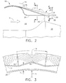
Figure 2 is an axial sectional view of a portion of the outer exhaust nozzle illustrated inFigure 1 in accordance with one embodiment. -
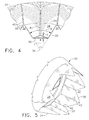
Figure 3 is a radial sectional view through a portion of the exhaust nozzle illustrated inFigure 2 and taken along line 3-3. -
Figure 4 is a radial sectional view through a portion of the exhaust nozzle illustrated inFigure 2 and taken along line 4-4. -
Figure 5 is a isometric view of the inner exhaust nozzle illustrated inFigure 1 in isolation. -
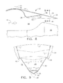
Figure 6 is an axial sectional view of the inner nozzle illustrated inFigure 1 and taken along line 6-6. -
Figure 7 is a radial sectional view of a portion of the exhaust nozzle illustrated inFigure 6 and taken along line 7-7. -
Figure 8 is an axial sectional view, likeFigure 6 , of the exhaust nozzle in accordance with another embodiment. -
Figure 9 is a radial sectional view through a portion of the exhaust nozzle illustrated inFigure 8 and taken along line 9-9. -
Figure 10 is axial sectional view, likeFigure 2 , of the exhaust nozzle in accordance with another embodiment. -
Figure 11 is a radial sectional view through the exhaust nozzle illustrated inFigure 10 and taken along line 11-11. - Illustrated schematically in
Figure 1 is an exemplary turbofan gasturbine aircraft engine 10 configured for powering an aircraft (not shown) in flight to supersonic flight speeds. The engine is axisymmetric about a longitudinal oraxial centerline axis 12. - The
engine 10 may have any conventional configuration including a multistage axial compressor for pressurizingair 14 which is mixed with fuel and ignited in a combustor for generatinghot combustion gases 16. An HPT extracts energy from the combustion gases to power the compressor, and a LPT extracts energy from the combustion gases to power an upstream fan. - The engine has various internal and external casings which define internal flow passages and bypass ducts for separately channeling the pressurized air and core gases therethrough. The engine may also include a fan-on-blade (FLADE) configuration which pressurizes the air in two separate annular flowpaths from a common row of fan blades. The pressurized air and core gases are typically discharged from the aft end of the engine in concentric streams either inverted or not depending upon the specific design of the engine.
- As indicated above, the exhaust flows 14,16 from the
engine 10 create noise when discharged into the atmosphere during aircraft propulsion. Accordingly, the engine includes at its aft end outer and inner annularacoustic exhaust nozzles common centerline axis 12. - In the exemplary inverted flow configuration illustrated in
Figure 1 , thecore combustion gases 16 are discharged through theouter nozzle 18, while thepressurized fan air 14 is discharged through theinner nozzle 20. In non-inverted flow, the fan air would be discharged through theouter nozzle 18, and thecore gases 16 discharged through theinner nozzle 20. And, thefreestream airflow 14 flows outside the nozzles as the engine propels the aircraft during flight operation. - The two
nozzles Figure 1 are specifically configured for improving mixing between the internal and external flowstreams for reducing maximum flow velocity and thereby attenuating or reducing noise during operation. The outeracoustic nozzle 18 is illustrated in a first exemplary embodiment inFigure 2-4 . - The
exhaust nozzle 18 includes concentric outer and inner shells orannular walls common centerline axis 12 illustrated inFigure 1 between forward and aft ends thereof. The forward end of the nozzle is suitably mounted to an aft frame in the engine in a conventional manner. - The two
shells triangular chevrons 28 which define a circumferentiallyserpentine trailing edge 30 of the nozzle. -
Figure 1 shows the outer row ofidentical chevrons 28 in uniform repetition around the nozzle circumference, with thetrailing edge 30 thereof varying in axial position along the axial length L of the chevrons to define the circumferentially serpentine configuration thereof. - As shown in
Figures 1 and4 , thechevrons 28 are spaced circumferentially apart by respective axially divergingslots 32 which complement the converging chevrons in the uniform row thereof. - As shown in
Figure 4 , eachchevron 28 is triangular in the aft direction and converges in lateral or circumferential width W axially between its forward orupstream base 34 and its aft ordownstream apex 36 along theserpentine trailing edge 30 on opposite lateral sides or edges of each chevron. - Correspondingly, each of the
slots 32 is also triangular between twoadjacent chevrons 28 and diverges axially aft in width from aroot notch 38 in the same axial plane as thechevron bases 34. The slots diverge in the aft direction and terminate at the common aft plane of thechevron apexes 36. - Since the two
shells chevron apexes 36, the chevrons are additionally radially serpentine circumferentially around the shells in addition to being circumferentially serpentine along the commontrailing edge 30 thereof. Eachchevron 28 therefore decreases in radial thickness T both axially and circumferentially to the thintrailing edge 30 which laterally bounds each chevron as illustrated inFigure 4 . - In particular, each chevron includes a central crown or
ridge 40 extending upstream or forwardly from theapex 36 symmetrically or equidistantly between the twoside edges 30 thereof. Thecentral ridge 40 continues forwardly past thechevron base 34 along the two shells to the forward portion thereof. - The
central ridges 40 corresponding with thechevrons 28 alternate with circumferentially adjacent corresponding valleys orflutes 42 extending axially forward from theslots 32 at theirforwardmost notches 38. Theridges 40 extend axially forwardly from the corresponding chevron apexes 36, and the cooperatingflutes 42 extend axially forwardly in parallel therewith from thecorresponding slot notches 38 to effect the radially serpentine configuration circumferentially around the shells. -
Figure 2 illustrates the double wall configuration of theexhaust nozzle 18 and its increasing thickness forward from the aft trailing edge, and then its decreasing thickness over its forward portion as desired. When thechevrons 28 are introduced into the double wall nozzle, the base ends thereof at theslot notches 38 have a substantial radial thickness greater than the uniform thickness of the conventional single-ply subsonic chevron nozzle disclosed in the Background. - The introduction of the diverging
slots 32 in a uniform thickness double shell would create a radially thick root notch which would act as an aerodynamic bluff body with associated drag loss therefrom. - In contrast, by introducing the
serpentine ridges 40 andflutes 42 around the circumference of the double wall nozzle illustrated in the first embodiment inFigures 1-4 , the twoshells chevron trailing edge 30 around the corresponding divergingslots 32. - In this way, each
chevron 28 has a thin trailing edge of minimum thickness along both side edges from theaft apex 36 to theroot notches 38 and then blends aerodynamically both circumferentially to thecentral ridge 40 as well as axially aft along theflutes 42 between the ridges as the two shells increase in radial spacing in the aft direction. - The double wall chevron nozzle therefore includes the original circumferentially
serpentine trailing edge 30 around the perimeter in addition to the radially serpentine configuration introduced by theelevated ridges 40 and intervening recessedflutes 42 which aerodynamically blend the flow surfaces of the nozzle along the perimeters of each chevron and intervening diverging slot. - A significant improvement in aerodynamic efficiency is thusly created by the duplex or double serpentine chevron nozzle to smoothly blend both external and internal flowstreams without the introduction of aft facing bluff bodies and associated aerodynamic loss therefrom.
-
Figure 1 illustrates two embodiments of theexhaust nozzles - In the first embodiment illustrated in
Figures 1-4 , theinner shell 26 is circular in section with a constant radius R from the centerline axis at each axial section, and theouter shell 24 is radially serpentine and varies in radial position to include theaxial ridges 40 and interveningaxial flutes 42. - In particular, the
inner shell 26 is cylindrical or conical as desired, and includes a smooth circular inner surface that defines aninternal exhaust duct 44 which terminates in anannular outlet 46 at thechevrons 28. - Correspondingly, the
outer shell 24 includes theexternal ridges 40 extending axially aft along the outer surface thereof. And, theexternal flutes 42 extend axially aft between theexternal ridges 40 to the respective divergingslots 32 between the chevrons. - In
Figure 2 , theinner shell 26 has a cylindrical configuration over its aft portion, with theouter shell 24 converging aft thereover. Accordingly, theexternal flutes 42 preferably begin at the forward end of the nozzle and then increase in radial depth axially aft along theridges 40 to theslots 32. - In this way, the
flutes 42 taper and blend at their forward ends into the uniform conical surface of the outer shell at its forward end, and also blend and taper to the divergingslots 32 at the aft ends thereof. -
Figures 5-7 illustrate theinner nozzle 20 in a second embodiment in which like reference numerals identify like parts, but differently located. In particular, theouter shell 24 in this embodiment is smoothly conical and has circular cross sections, whereas theinner shell 26 is radially serpentine to cooperate with the circumferentiallyserpentine trailing edge 30 of the row ofchevrons 28. - The
outer shell 24 in this embodiment has a smooth circular outer surface over which the external flow may smoothly travel. Theinner shell 26 in this embodiment varies circumferentially in radial position to include theinternal ridges 40 extending axially aft along the inner surface thereof. The cooperatinginternal flutes 42 extend axially aft between theinternal ridges 40 to the corresponding divergingslots 32 to define anotherexhaust duct 48 terminating in anotheroutlet 50 at thechevrons 28. - The two
exhaust nozzles Figures 1-7 are used in combination to define theouter exhaust duct 44 andouter nozzle outlet 46 surrounding theinner exhaust duct 48 andinner exhaust outlet 50. - In
Figure 2 , theouter duct 44 carries theinverted core gases 16, withambient airflow 14 being channeled outside the outer duct. - In
Figure 6 , theinner duct 48 carries theinverted fan air 14, with thecore flow 16 being discharged outside theinner nozzle 20. - In alternate embodiments, the externally
serpentine nozzle 18 may be used alone, and the internallyserpentine nozzle 20 may also be used alone where aerodynamic performance may be enhanced thereby. - In the
Figure 6 embodiment, theinternal flutes 42 have substantially constant radial depth axially aft along the correspondingridges 40 over most of the aft portion of the exhaust nozzle to theaft slots 32. - Since the outer and
inner shells ridges 40 andflutes 42 may be introduced in either the outer or inner shells in various embodiments including the two embodiments illustrated inFigures 2 and6 in contrast. - Further embodiments or permutations of the ridges and flutes in the double wall exhaust nozzle are also possible.
-
Figures 8 and 9 illustrate another embodiment of an exhaust nozzle, designated 52, which is generally similar to the internalserpentine nozzle 20 illustrated inFigures 5-7 . Like reference numerals indicate like features. - The two
nozzles internal flutes 42 inFigure 8 increase in radial depth axially aft along the correspondingridges 40 to the corresponding divergingslots 32. This permits, for example, different flow area control of theexhaust duct 44 in accordance with the specific requirements of the gas turbine engine. - The
inner shell 26 illustrated inFigure 8 has a generally cylindrical profile with the correspondinginternal ridges 40 extending axially therealong. Theinternal flutes 42 commence at the relatively thick forward end of the nozzle and increase in depth and radius aft where they meet the diverging slots. -
Figures 10 and 11 illustrate yet another embodiment of an exhaust nozzle designated 54, which is a variation of the externalserpentine nozzle 18 illustrated inFigures 1-4 . Like reference numerals indicate like features. - In this embodiment of the
nozzle 54, theexternal flutes 42 have a substantially constant radial depth axially aft along theridges 40 to the divergingslots 32 over most of the axial length of the nozzle. The ridges and flutes may commence well upstream of the converging portion of the nozzle and continue with uniform height and depth over the converging aft portion of the nozzle to thechevrons 28. - This configuration may be used to advantage to control aerodynamic performance of the external flow field outside the
nozzle 54 as it blends and mixes with the internal flowstream discharged from theexhaust duct 44. - Presented above are two basic configurations of the fluted chevron exhaust nozzle in which either the inner shell or outer shell may be radially serpentine with the cooperating axial ridges and flutes, while the other shell remains cylindrical or conical in profile, with a smooth circumferentially circular perimeter.
- And, the corresponding flutes in these two basic embodiments may have two further configurations including constant radial depth along most of their axial extent, or may smoothly vary or taper in radial depth as desired for providing a smooth aerodynamic transition and blending with the corresponding diverging slots between the locally thick chevrons.
- In these four basic embodiments disclosed above for
Figures 4 ,7 ,9 , and11 , each of thechevrons 28 is substantially flat between themiddle ridge 40 and the converging side edges 30 thereof between the base and apex. Since the chevrons decrease in thickness between their bases and apexes, the outer and inner surfaces thereof may be axially straight. - This is in contrast with the compound curvature or bowl configuration found in the original chevron nozzle disclosed in the Background. In that patent, the chevron nozzle was basically single-ply with uniform thickness chevrons being arcuate both circumferentially and axially.
- In the double wall construction of the chevrons, the axially straight outer and inner surfaces thereof provide both substantial noise suppression and aerodynamic efficiency. If desired, the chevrons may be configured with axially arcuate inner or outer surfaces, or both, in the manner of the previous patent if additional benefits therefrom may be obtained.
- In the two embodiments illustrated in
Figures 4 and11 , thechevron ridge 40 is formed in theouter shell 24, and theinner shell 26 is circumferentially arcuate or concave inwardly and forms with the outer shell a radially outwardly projecting triangle in section. Each chevron is therefore triangular both axially and radially in external profile. - In the two embodiments illustrated in
Figures 7 and9 , thechevron ridge 40 is formed in theinner shell 26, and theouter shell 24 is circumferentially arcuate or convex outwardly and forms with the inner shell a radially inwardly projecting triangle in section. Yet again, each chevron is both axially and radially triangular in profile. - The various forms of the chevron nozzles disclosed above may be used in various configurations of gas turbine aircraft engines where they can provide noise attenuation without undesirable aerodynamic performance penalty. The chevrons may be introduced in an otherwise conventional exhaust nozzle, such as the typical conical nozzle found in modern jet engines.
-
Figure 2 illustrates in dashed line the conical profile of atypical reference nozzle 56. The reference nozzle has a circular outlet with a specific flow area. - By introducing the chevrons around the outlet end of the nozzle, the effective outlet area is changed by the circumferentially serpentine trailing edge of the nozzle which varies in axial position around the circumference thereof.
- Accordingly, the chevron nozzle is suitably designed in geometry to match the required discharge flow area of the reference nozzle, which typically places the
root notches 38 upstream in axial position from the aft end of thereference nozzle 56. - The flow area requirements of the various nozzles are dictated by the aerodynamic requirements of the specific exhaust duct through which exhaust flow is discharged. These flow area requirements depend on the thermodynamic and aerodynamic performance of the exhaust flow, such as the hot core gases or the cold fan air.
- Nevertheless, the requisite flow area configuration of the nozzle for a given application may be readily introduced into the various forms of the chevron nozzle having the double wall configuration thereof.
- As initially shown in
Figure 1 , eachnozzle outer nozzle 18 cooperates with the forward portion of theinner nozzle 20 to define theannular exhaust duct 44 therebetween as shown inFigure 2 . - The
inner nozzle 20 cooperates with the forward portion of theinternal plug 22 to define the flow area distribution for theexhaust duct 48 therebetween as shown inFigure 6 . - As shown in
Figures 2 ,6 ,8 , and10 the various forms of the chevron nozzle may cooperate with the various forms of theinner cowls corresponding exhaust ducts nozzle outlets - Whereas the typical subsonic exhaust nozzle for commercial aircraft engines converges to a throat of minimum flow area at the aft end thereof, the
supersonic turbofan engine 10 illustrated inFigure 1 will experience improved performance with a converging-diverging (CD) exhaust nozzle specifically configured for supersonic operation of the engine. -
Figures 2 ,6 ,8 , and10 illustrate various configurations of the chevron nozzle and cooperating inner cowls which may be used in various engine designs to control exhaust duct flow area and effect CD nozzles in various configurations. - In the several embodiments, the exhaust ducts defined by the
inner shell 26 converges aft in flow area to effect a throat, designated A8, of minimum flow area at the base of thechevrons 28. The inner surface of theinner shell 26 cooperates with the outer surface of the inner cowl which increases in diameter in the aft direction to effect the converging flow area. - From the throat A8 of minimal flow area, the
exhaust duct 44 then diverges or increases aft in flow area along the chevrons for effecting a larger outlet flow area, commonly designated A9. - The introduction of the double wall exhaust nozzle disclosed above in various embodiments permits aerodynamic tailoring of both the inner shell, and internal exhaust duct, and the outer shell for their different cooperation with the different flowstreams channeled therealong.
- The nozzle inner shell may be specifically tailored in configuration for effecting the desired converging-diverging area profile of the internal exhaust duct for maximizing aerodynamic performance of the engine, particularly at supersonic operation of the engine.
- The nozzle outer shell may be differently tailored for maximum nozzle efficiency with the outer flowstream.
- And, the fluted chevron nozzles permit aerodynamic blending of the internal and external flowstreams where they mix in the diverging slots between the chevrons for maximizing aerodynamic efficiency while additionally providing the desired acoustic attenuation of the exhaust noise.
- The double wall construction of the chevron nozzle disclosed above therefore introduces additional design features which may be suitably varied for enhancing noise attenuation while maintaining good aerodynamic performance in various forms of aircraft turbofan gas turbine engines, now including supersonic in addition to subsonic engines.
- While there have been described herein what are considered to be preferred and exemplary embodiments of the present invention, other modifications of the invention shall be apparent to those skilled in the art from the teachings herein, and it is, therefore, desired to be secured in the appended claims all such modifications as fall within the true spirit and scope of the invention.
- Accordingly, what is desired to be secured by Letters Patent is the invention as defined and differentiated in the following claims in which I claim:
Claims (10)
- A gas turbine engine exhaust nozzle (18,20,52,54) comprising:coaxial outer and inner shells (24,26) converging aft to a row of triangular chevrons (28) spaced apart circumferentially by respective diverging slots (32) along a circumferentially serpentine trailing edge (30); andeach of said chevrons (28) includes a central ridge (40) extending axially forward and circumferentially between corresponding flutes (42) extending axially forward from said slots (32).
- A nozzle according to claim 1 wherein said row of chevrons (28) is both circumferentially and radially serpentine circumferentially around said shells (24,26), and each chevron (28) converges in radial thickness from said ridge (40) both circumferentially and axially to said serpentine trailing edge (30) around said diverging slots (32).
- A nozzle according to claim 1 or claim 2 wherein:said inner shell (26) includes a smooth circular inner surface defining an exhaust duct (44) terminating in an outlet (46) at said chevrons; andsaid outer shell (24) includes said ridges (40) extending axially aft along the outer surface thereof, and said flutes (42) extend axially aft between said ridges (40) to said slots (32).
- A nozzle according to claim 3 wherein said flutes (42) increase in depth axially aft along said ridges (40) to said slots (32).
- A nozzle according to claim 3 wherein said flutes (42) have a substantially constant depth axially aft along said ridges (40) to said slots (32).
- A nozzle according to claim 1 or claim 2 wherein:said outer shell (24) includes a smooth circular outer surface; andsaid inner shell (26) includes said ridges (40) extending axially aft along the inner surface thereof, and said flutes (42) extend axially aft between said ridges (40) to said slots (32) to define an exhaust duct (48) terminating in an outlet (50) at said chevrons (28).
- A nozzle according to claim 6 wherein said flutes (42) increase in depth axially aft along said ridges (40) to said slots (32).
- A nozzle according to claim 6 wherein said flutes (42) have substantially constant depth axially aft along said ridges (40) to said slots (32).
- A nozzle according to claim 1 or claim 2 wherein each of said chevrons (28) is substantially flat between said ridge (40) and said trailing edge (30) thereof in one of said shells (24,26), and the other shell (26,24) is circumferentially arcuate to form therewith a radially projecting triangle.
- A nozzle according to claim 1 or claim 2 further comprising an inner cowl (20,22) spaced radially inwardly from said inner shell (26) to define therewith an annular exhaust duct (44,48) terminating in an outlet (46,50) at said chevrons (28) and converging aft in flow area to effect a throat of minimum flow area at said chevrons (28), and diverging aft in flow area from said throat.
Applications Claiming Priority (1)
| Application Number | Priority Date | Filing Date | Title |
|---|---|---|---|
| US11/751,174 US7963099B2 (en) | 2007-05-21 | 2007-05-21 | Fluted chevron exhaust nozzle |
Publications (3)
| Publication Number | Publication Date |
|---|---|
| EP1995441A2 true EP1995441A2 (en) | 2008-11-26 |
| EP1995441A3 EP1995441A3 (en) | 2011-03-09 |
| EP1995441B1 EP1995441B1 (en) | 2019-01-23 |
Family
ID=39400439
Family Applications (1)
| Application Number | Title | Priority Date | Filing Date |
|---|---|---|---|
| EP08152999.2A Ceased EP1995441B1 (en) | 2007-05-21 | 2008-03-19 | Gas turbine engine exhaust nozzle |
Country Status (3)
| Country | Link |
|---|---|
| US (1) | US7963099B2 (en) |
| EP (1) | EP1995441B1 (en) |
| JP (1) | JP5466371B2 (en) |
Cited By (5)
| Publication number | Priority date | Publication date | Assignee | Title |
|---|---|---|---|---|
| WO2010011381A1 (en) * | 2008-06-26 | 2010-01-28 | General Electric Company | Duplex tab exhaust nozzle |
| WO2010144181A1 (en) * | 2009-06-12 | 2010-12-16 | The Boeing Company | Gas turbine engine assembly and corresponding operating method |
| FR2986831A1 (en) * | 2012-02-10 | 2013-08-16 | Snecma | METHOD FOR DEFINING THE FORM OF A CONVERGENT-DIVERGENT TUBE OF A CORRESPONDING TURBOMACHINE AND CONVERGENT-DIVERGENT TUBE |
| US9511873B2 (en) | 2012-03-09 | 2016-12-06 | The Boeing Company | Noise-reducing engine nozzle system |
| CN110998080A (en) * | 2017-08-21 | 2020-04-10 | 赛峰飞机发动机公司 | Improved acoustic secondary nozzle |
Families Citing this family (17)
| Publication number | Priority date | Publication date | Assignee | Title |
|---|---|---|---|---|
| JP4830836B2 (en) * | 2006-12-18 | 2011-12-07 | 株式会社Ihi | Jet jet exhaust nozzle and jet engine |
| US7926285B2 (en) * | 2007-07-18 | 2011-04-19 | General Electric Company | Modular chevron exhaust nozzle |
| US20100192590A1 (en) * | 2009-01-30 | 2010-08-05 | Michael Robert Johnson | Thermally balanced materials |
| US20100193605A1 (en) * | 2009-01-30 | 2010-08-05 | Michael Robert Johnson | Thermally balanced aero structures |
| US9964070B2 (en) * | 2009-06-12 | 2018-05-08 | The Boeing Company | Gas turbine engine nozzle including housing having scalloped root regions |
| US8635875B2 (en) | 2010-04-29 | 2014-01-28 | Pratt & Whitney Canada Corp. | Gas turbine engine exhaust mixer including circumferentially spaced-apart radial rows of tabs extending downstream on the radial walls, crests and troughs |
| JP5842211B2 (en) * | 2011-01-21 | 2016-01-13 | 国立研究開発法人宇宙航空研究開発機構 | Aerodynamic noise reduction device |
| FR3008739B1 (en) * | 2013-07-18 | 2017-03-24 | Snecma | TUYERE OF A TURBOMACHINE EQUIPPED WITH CHEVRONS WITH NON-AXI-SYMMETRIC INTERNAL SIDE. |
| US10550704B2 (en) | 2013-08-23 | 2020-02-04 | United Technologies Corporation | High performance convergent divergent nozzle |
| US10371090B2 (en) | 2014-01-13 | 2019-08-06 | United Technologies Corporation | Variable area exhaust mixer for a gas turbine engine |
| US10094332B2 (en) * | 2014-09-03 | 2018-10-09 | The Boeing Company | Core cowl for a turbofan engine |
| JP2017198498A (en) * | 2016-04-26 | 2017-11-02 | 株式会社Soken | Flow measuring device |
| US11440671B2 (en) * | 2019-01-24 | 2022-09-13 | Amazon Technologies, Inc. | Adjustable motor fairings for aerial vehicles |
| CN112502853B (en) * | 2020-11-27 | 2021-11-02 | 中国商用飞机有限责任公司 | Nozzle, jet engine and jet aircraft equipped with the nozzle |
| US12292014B2 (en) * | 2020-12-21 | 2025-05-06 | Rohr, Inc. | Gas turbine engine exhaust chevrons |
| CN113944565B (en) * | 2021-10-19 | 2022-06-28 | 中国科学院工程热物理研究所 | Tail nozzle structure for improving vibration characteristic |
| CN115450791B (en) * | 2022-09-12 | 2025-06-20 | 西北工业大学 | An S-bend nozzle with a triangular pyramidal reinforcement structure |
Citations (1)
| Publication number | Priority date | Publication date | Assignee | Title |
|---|---|---|---|---|
| US6360528B1 (en) | 1997-10-31 | 2002-03-26 | General Electric Company | Chevron exhaust nozzle for a gas turbine engine |
Family Cites Families (56)
| Publication number | Priority date | Publication date | Assignee | Title |
|---|---|---|---|---|
| US2636780A (en) * | 1950-08-17 | 1953-04-28 | Frank T Barnes | Device for atomizing grease |
| US3153319A (en) * | 1952-07-25 | 1964-10-20 | Young Alec David | Jet noise suppression means |
| US2997845A (en) * | 1957-03-22 | 1961-08-29 | Rolls Royce | Jet propulsion nozzle adjustable to give forward and reverse thrusts |
| GB838617A (en) * | 1957-09-02 | 1960-06-22 | Rolls Royce | Improved jet noise suppressor nozzle |
| US3084507A (en) * | 1958-06-17 | 1963-04-09 | Douglas Aircraft Co Inc | Jet engine sound suppressor and reverser |
| US3568792A (en) * | 1969-06-18 | 1971-03-09 | Rohr Corp | Sound-suppressing and thrust-reversing apparatus |
| FR2126922B1 (en) * | 1971-01-20 | 1975-01-17 | Snecma | |
| GB2082259B (en) * | 1980-08-15 | 1984-03-07 | Rolls Royce | Exhaust flow mixers and nozzles |
| US4401269A (en) * | 1980-09-26 | 1983-08-30 | United Technologies Corporation | Lobe mixer for gas turbine engine |
| WO1983003281A1 (en) * | 1982-03-17 | 1983-09-29 | Klees, Garry, William | Internally ventilated noise suppressor with large plug nozzle |
| US4592201A (en) * | 1982-07-12 | 1986-06-03 | General Electric Company | Turbofan mixed flow exhaust system |
| GB2146702B (en) | 1983-09-14 | 1987-12-23 | Rolls Royce | Exhaust mixer for turbofan aeroengine |
| US4872612A (en) * | 1985-08-05 | 1989-10-10 | Morton Thiokol, Inc. | Rocket motor extendible nozzle exit cone |
| US4830315A (en) * | 1986-04-30 | 1989-05-16 | United Technologies Corporation | Airfoil-shaped body |
| US4754924A (en) * | 1987-04-03 | 1988-07-05 | Shannon Aubrey J | Variable geometry nozzle |
| US5402963A (en) * | 1992-09-15 | 1995-04-04 | General Electric Company | Acoustically shielded exhaust system for high thrust jet engines |
| GB2289921A (en) | 1994-06-03 | 1995-12-06 | A E Harris Limited | Nozzle for turbofan aeroengines |
| US6082635A (en) * | 1996-06-12 | 2000-07-04 | The United States Of America As Represented By The Administrator Of The National Aeronautics And Space Administration | Undulated nozzle for enhanced exit area mixing |
| US5908159A (en) * | 1997-02-24 | 1999-06-01 | The Boeing Company | Aircraft chute ejector nozzle |
| US6012281A (en) * | 1997-08-18 | 2000-01-11 | United Technologies Corporation | Noise suppressing fluid mixing system for a turbine engine |
| US6314721B1 (en) * | 1998-09-04 | 2001-11-13 | United Technologies Corporation | Tabbed nozzle for jet noise suppression |
| US6487848B2 (en) * | 1998-11-06 | 2002-12-03 | United Technologies Corporation | Gas turbine engine jet noise suppressor |
| US6612106B2 (en) * | 2000-05-05 | 2003-09-02 | The Boeing Company | Segmented mixing device having chevrons for exhaust noise reduction in jet engines |
| US7065957B2 (en) * | 2000-05-05 | 2006-06-27 | The Boeing Company | Segmented mixing device for jet engines and aircraft |
| GB0105349D0 (en) * | 2001-03-03 | 2001-04-18 | Rolls Royce Plc | Gas turbine engine exhaust nozzle |
| US7578132B2 (en) * | 2001-03-03 | 2009-08-25 | Rolls-Royce Plc | Gas turbine engine exhaust nozzle |
| US6532729B2 (en) * | 2001-05-31 | 2003-03-18 | General Electric Company | Shelf truncated chevron exhaust nozzle for reduction of exhaust noise and infrared (IR) signature |
| US7040553B2 (en) * | 2001-07-03 | 2006-05-09 | Hunter Industries, Inc. | Rotor type sprinkler with reversing mechanism including sliding clutch and driven bevel gears |
| FR2829802B1 (en) * | 2001-09-19 | 2004-05-28 | Centre Nat Rech Scient | DEVICE FOR CONTROLLING MIXTURE OF PROPELLENT JETS FOR AN AIRCRAFT REACTOR |
| EP1485600B1 (en) * | 2002-02-22 | 2009-11-04 | THE NORDAM GROUP, Inc. | Duplex mixer exhaust nozzle |
| US6658839B2 (en) * | 2002-02-28 | 2003-12-09 | The Boeing Company | Convergent/divergent segmented exhaust nozzle |
| US6718752B2 (en) * | 2002-05-29 | 2004-04-13 | The Boeing Company | Deployable segmented exhaust nozzle for a jet engine |
| FR2855558B1 (en) * | 2003-05-28 | 2005-07-15 | Snecma Moteurs | TURBOMACHINE TUBE WITH NOISE REDUCTION |
| US7395657B2 (en) * | 2003-10-20 | 2008-07-08 | General Electric Company | Flade gas turbine engine with fixed geometry inlet |
| US7093423B2 (en) * | 2004-01-20 | 2006-08-22 | General Electric Company | Methods and apparatus for operating gas turbine engines |
| US7305817B2 (en) * | 2004-02-09 | 2007-12-11 | General Electric Company | Sinuous chevron exhaust nozzle |
| US7114323B2 (en) * | 2004-03-05 | 2006-10-03 | United Technologies Corporation | Jet exhaust noise reduction system and method |
| FR2868131B1 (en) * | 2004-03-25 | 2006-06-09 | Airbus France Sas | PRIME TUBE WITH CHEVRONS FOR A DOUBLE FLOW AIRCRAFT AIRCRAFT AND AIRCRAFT COMPRISING SUCH TUYERE |
| US7246481B2 (en) * | 2004-03-26 | 2007-07-24 | General Electric Company | Methods and apparatus for operating gas turbine engines |
| US7174704B2 (en) * | 2004-07-23 | 2007-02-13 | General Electric Company | Split shroud exhaust nozzle |
| US7216831B2 (en) | 2004-11-12 | 2007-05-15 | The Boeing Company | Shape changing structure |
| US7546727B2 (en) * | 2004-11-12 | 2009-06-16 | The Boeing Company | Reduced noise jet engine |
| US7340883B2 (en) * | 2004-11-12 | 2008-03-11 | The Boeing Company | Morphing structure |
| US7739872B2 (en) * | 2005-02-14 | 2010-06-22 | United Technologies Corporation | Cooled dual wall liner closeout |
| GB0505246D0 (en) | 2005-03-15 | 2005-04-20 | Rolls Royce Plc | Engine noise |
| US7578133B2 (en) * | 2005-03-28 | 2009-08-25 | United Technologies Corporation | Reduced radar cross section exhaust nozzle assembly |
| US7543452B2 (en) * | 2005-08-10 | 2009-06-09 | United Technologies Corporation | Serrated nozzle trailing edge for exhaust noise suppression |
| FR2890696B1 (en) * | 2005-09-12 | 2010-09-17 | Airbus France | TURBOMOTEUR WITH ATTENUATED JET NOISE |
| US7624567B2 (en) * | 2005-09-20 | 2009-12-01 | United Technologies Corporation | Convergent divergent nozzle with interlocking divergent flaps |
| GB0606823D0 (en) * | 2006-04-05 | 2006-05-17 | Rolls Royce Plc | Adjustment assembly |
| US7721551B2 (en) * | 2006-06-29 | 2010-05-25 | United Technologies Corporation | Fan variable area nozzle for a gas turbine engine fan nacelle |
| US7520124B2 (en) * | 2006-09-12 | 2009-04-21 | United Technologies Corporation | Asymmetric serrated nozzle for exhaust noise reduction |
| US7966826B2 (en) * | 2007-02-14 | 2011-06-28 | The Boeing Company | Systems and methods for reducing noise from jet engine exhaust |
| US8020367B2 (en) * | 2007-03-16 | 2011-09-20 | General Electric Company | Nozzle with yaw vectoring vane |
| US8671693B2 (en) * | 2008-01-11 | 2014-03-18 | George C. P. Straza | Thermally conductive structure |
| US7716932B2 (en) * | 2008-07-24 | 2010-05-18 | Spirit Aerosystems, Inc. | Dilating fan duct nozzle |
-
2007
- 2007-05-21 US US11/751,174 patent/US7963099B2/en active Active
-
2008
- 2008-03-19 EP EP08152999.2A patent/EP1995441B1/en not_active Ceased
- 2008-03-19 JP JP2008070616A patent/JP5466371B2/en not_active Expired - Fee Related
Patent Citations (1)
| Publication number | Priority date | Publication date | Assignee | Title |
|---|---|---|---|---|
| US6360528B1 (en) | 1997-10-31 | 2002-03-26 | General Electric Company | Chevron exhaust nozzle for a gas turbine engine |
Cited By (9)
| Publication number | Priority date | Publication date | Assignee | Title |
|---|---|---|---|---|
| WO2010011381A1 (en) * | 2008-06-26 | 2010-01-28 | General Electric Company | Duplex tab exhaust nozzle |
| GB2474377A (en) * | 2008-06-26 | 2011-04-13 | Gen Electric | Duplex tab exhaust nozzle |
| US8087250B2 (en) | 2008-06-26 | 2012-01-03 | General Electric Company | Duplex tab exhaust nozzle |
| GB2474377B (en) * | 2008-06-26 | 2012-02-29 | Gen Electric | Duplex tab exhaust nozzle |
| WO2010144181A1 (en) * | 2009-06-12 | 2010-12-16 | The Boeing Company | Gas turbine engine assembly and corresponding operating method |
| FR2986831A1 (en) * | 2012-02-10 | 2013-08-16 | Snecma | METHOD FOR DEFINING THE FORM OF A CONVERGENT-DIVERGENT TUBE OF A CORRESPONDING TURBOMACHINE AND CONVERGENT-DIVERGENT TUBE |
| US9249755B2 (en) | 2012-02-10 | 2016-02-02 | Snecma | Method for defining the shape of a turbomachine convergent-divergent nozzle, and corresponding convergent-divergent nozzle |
| US9511873B2 (en) | 2012-03-09 | 2016-12-06 | The Boeing Company | Noise-reducing engine nozzle system |
| CN110998080A (en) * | 2017-08-21 | 2020-04-10 | 赛峰飞机发动机公司 | Improved acoustic secondary nozzle |
Also Published As
| Publication number | Publication date |
|---|---|
| EP1995441B1 (en) | 2019-01-23 |
| JP5466371B2 (en) | 2014-04-09 |
| US7963099B2 (en) | 2011-06-21 |
| EP1995441A3 (en) | 2011-03-09 |
| US20090071164A1 (en) | 2009-03-19 |
| JP2008286187A (en) | 2008-11-27 |
Similar Documents
| Publication | Publication Date | Title |
|---|---|---|
| EP1995441B1 (en) | Gas turbine engine exhaust nozzle | |
| US6360528B1 (en) | Chevron exhaust nozzle for a gas turbine engine | |
| US6532729B2 (en) | Shelf truncated chevron exhaust nozzle for reduction of exhaust noise and infrared (IR) signature | |
| US6786038B2 (en) | Duplex mixer exhaust nozzle | |
| EP1561939B1 (en) | Sinuous chevron exhaust nozzle | |
| CA2728527C (en) | Duplex tab exhaust nozzle | |
| US6502383B1 (en) | Stub airfoil exhaust nozzle | |
| EP1939438B1 (en) | Duct burning mixed flow turbofan | |
| EP1344928B1 (en) | Variable area nozzle | |
| EP1757860A2 (en) | Trapped vortex cavity afterburner | |
| US20020164249A1 (en) | Gas turbine engine exhaust nozzle | |
| JPS6338670A (en) | Outlet structure of axial-flow gas turbine engine | |
| EP2587037A2 (en) | Turbofan engine mixer assembly | |
| US20040244357A1 (en) | Divergent chevron nozzle and method | |
| US11920539B1 (en) | Gas turbine exhaust nozzle noise abatement | |
| Gutmark | Duplex tab exhaust nozzle |
Legal Events
| Date | Code | Title | Description |
|---|---|---|---|
| PUAI | Public reference made under article 153(3) epc to a published international application that has entered the european phase |
Free format text: ORIGINAL CODE: 0009012 |
|
| AK | Designated contracting states |
Kind code of ref document: A2 Designated state(s): AT BE BG CH CY CZ DE DK EE ES FI FR GB GR HR HU IE IS IT LI LT LU LV MC MT NL NO PL PT RO SE SI SK TR |
|
| AX | Request for extension of the european patent |
Extension state: AL BA MK RS |
|
| PUAL | Search report despatched |
Free format text: ORIGINAL CODE: 0009013 |
|
| AK | Designated contracting states |
Kind code of ref document: A3 Designated state(s): AT BE BG CH CY CZ DE DK EE ES FI FR GB GR HR HU IE IS IT LI LT LU LV MC MT NL NO PL PT RO SE SI SK TR |
|
| AX | Request for extension of the european patent |
Extension state: AL BA MK RS |
|
| RIC1 | Information provided on ipc code assigned before grant |
Ipc: F02K 1/38 20060101ALI20110201BHEP Ipc: F02K 1/48 20060101AFI20080527BHEP |
|
| 17P | Request for examination filed |
Effective date: 20110909 |
|
| AKX | Designation fees paid |
Designated state(s): DE FR GB |
|
| 17Q | First examination report despatched |
Effective date: 20170213 |
|
| GRAP | Despatch of communication of intention to grant a patent |
Free format text: ORIGINAL CODE: EPIDOSNIGR1 |
|
| INTG | Intention to grant announced |
Effective date: 20180928 |
|
| GRAS | Grant fee paid |
Free format text: ORIGINAL CODE: EPIDOSNIGR3 |
|
| GRAA | (expected) grant |
Free format text: ORIGINAL CODE: 0009210 |
|
| AK | Designated contracting states |
Kind code of ref document: B1 Designated state(s): DE FR GB |
|
| REG | Reference to a national code |
Ref country code: GB Ref legal event code: FG4D |
|
| REG | Reference to a national code |
Ref country code: DE Ref legal event code: R096 Ref document number: 602008058833 Country of ref document: DE |
|
| REG | Reference to a national code |
Ref country code: DE Ref legal event code: R097 Ref document number: 602008058833 Country of ref document: DE |
|
| PLBE | No opposition filed within time limit |
Free format text: ORIGINAL CODE: 0009261 |
|
| STAA | Information on the status of an ep patent application or granted ep patent |
Free format text: STATUS: NO OPPOSITION FILED WITHIN TIME LIMIT |
|
| 26N | No opposition filed |
Effective date: 20191024 |
|
| PGFP | Annual fee paid to national office [announced via postgrant information from national office to epo] |
Ref country code: DE Payment date: 20200218 Year of fee payment: 13 Ref country code: GB Payment date: 20200221 Year of fee payment: 13 |
|
| PGFP | Annual fee paid to national office [announced via postgrant information from national office to epo] |
Ref country code: FR Payment date: 20200220 Year of fee payment: 13 |
|
| REG | Reference to a national code |
Ref country code: DE Ref legal event code: R119 Ref document number: 602008058833 Country of ref document: DE |
|
| GBPC | Gb: european patent ceased through non-payment of renewal fee |
Effective date: 20210319 |
|
| PG25 | Lapsed in a contracting state [announced via postgrant information from national office to epo] |
Ref country code: GB Free format text: LAPSE BECAUSE OF NON-PAYMENT OF DUE FEES Effective date: 20210319 Ref country code: FR Free format text: LAPSE BECAUSE OF NON-PAYMENT OF DUE FEES Effective date: 20210331 Ref country code: DE Free format text: LAPSE BECAUSE OF NON-PAYMENT OF DUE FEES Effective date: 20211001 |