EP2006604A1 - Optical module for vehicular lighting device - Google Patents
Optical module for vehicular lighting device Download PDFInfo
- Publication number
- EP2006604A1 EP2006604A1 EP08158436A EP08158436A EP2006604A1 EP 2006604 A1 EP2006604 A1 EP 2006604A1 EP 08158436 A EP08158436 A EP 08158436A EP 08158436 A EP08158436 A EP 08158436A EP 2006604 A1 EP2006604 A1 EP 2006604A1
- Authority
- EP
- European Patent Office
- Prior art keywords
- module according
- module
- folder
- optical axis
- transparent block
- Prior art date
- Legal status (The legal status is an assumption and is not a legal conclusion. Google has not performed a legal analysis and makes no representation as to the accuracy of the status listed.)
- Granted
Links
Images


Classifications
-
- F—MECHANICAL ENGINEERING; LIGHTING; HEATING; WEAPONS; BLASTING
- F21—LIGHTING
- F21S—NON-PORTABLE LIGHTING DEVICES; SYSTEMS THEREOF; VEHICLE LIGHTING DEVICES SPECIALLY ADAPTED FOR VEHICLE EXTERIORS
- F21S41/00—Illuminating devices specially adapted for vehicle exteriors, e.g. headlamps
- F21S41/60—Illuminating devices specially adapted for vehicle exteriors, e.g. headlamps characterised by a variable light distribution
- F21S41/68—Illuminating devices specially adapted for vehicle exteriors, e.g. headlamps characterised by a variable light distribution by acting on screens
- F21S41/683—Illuminating devices specially adapted for vehicle exteriors, e.g. headlamps characterised by a variable light distribution by acting on screens by moving screens
- F21S41/689—Flaps, i.e. screens pivoting around one of their edges
-
- F—MECHANICAL ENGINEERING; LIGHTING; HEATING; WEAPONS; BLASTING
- F21—LIGHTING
- F21S—NON-PORTABLE LIGHTING DEVICES; SYSTEMS THEREOF; VEHICLE LIGHTING DEVICES SPECIALLY ADAPTED FOR VEHICLE EXTERIORS
- F21S41/00—Illuminating devices specially adapted for vehicle exteriors, e.g. headlamps
- F21S41/10—Illuminating devices specially adapted for vehicle exteriors, e.g. headlamps characterised by the light source
- F21S41/14—Illuminating devices specially adapted for vehicle exteriors, e.g. headlamps characterised by the light source characterised by the type of light source
- F21S41/141—Light emitting diodes [LED]
- F21S41/143—Light emitting diodes [LED] the main emission direction of the LED being parallel to the optical axis of the illuminating device
- F21S41/145—Light emitting diodes [LED] the main emission direction of the LED being parallel to the optical axis of the illuminating device the main emission direction of the LED being opposite to the main emission direction of the illuminating device
-
- F—MECHANICAL ENGINEERING; LIGHTING; HEATING; WEAPONS; BLASTING
- F21—LIGHTING
- F21S—NON-PORTABLE LIGHTING DEVICES; SYSTEMS THEREOF; VEHICLE LIGHTING DEVICES SPECIALLY ADAPTED FOR VEHICLE EXTERIORS
- F21S41/00—Illuminating devices specially adapted for vehicle exteriors, e.g. headlamps
- F21S41/20—Illuminating devices specially adapted for vehicle exteriors, e.g. headlamps characterised by refractors, transparent cover plates, light guides or filters
- F21S41/25—Projection lenses
- F21S41/275—Lens surfaces, e.g. coatings or surface structures
-
- F—MECHANICAL ENGINEERING; LIGHTING; HEATING; WEAPONS; BLASTING
- F21—LIGHTING
- F21S—NON-PORTABLE LIGHTING DEVICES; SYSTEMS THEREOF; VEHICLE LIGHTING DEVICES SPECIALLY ADAPTED FOR VEHICLE EXTERIORS
- F21S41/00—Illuminating devices specially adapted for vehicle exteriors, e.g. headlamps
- F21S41/20—Illuminating devices specially adapted for vehicle exteriors, e.g. headlamps characterised by refractors, transparent cover plates, light guides or filters
- F21S41/28—Cover glass
-
- F—MECHANICAL ENGINEERING; LIGHTING; HEATING; WEAPONS; BLASTING
- F21—LIGHTING
- F21S—NON-PORTABLE LIGHTING DEVICES; SYSTEMS THEREOF; VEHICLE LIGHTING DEVICES SPECIALLY ADAPTED FOR VEHICLE EXTERIORS
- F21S41/00—Illuminating devices specially adapted for vehicle exteriors, e.g. headlamps
- F21S41/20—Illuminating devices specially adapted for vehicle exteriors, e.g. headlamps characterised by refractors, transparent cover plates, light guides or filters
- F21S41/285—Refractors, transparent cover plates, light guides or filters not provided in groups F21S41/24 - F21S41/2805
-
- F—MECHANICAL ENGINEERING; LIGHTING; HEATING; WEAPONS; BLASTING
- F21—LIGHTING
- F21S—NON-PORTABLE LIGHTING DEVICES; SYSTEMS THEREOF; VEHICLE LIGHTING DEVICES SPECIALLY ADAPTED FOR VEHICLE EXTERIORS
- F21S41/00—Illuminating devices specially adapted for vehicle exteriors, e.g. headlamps
- F21S41/30—Illuminating devices specially adapted for vehicle exteriors, e.g. headlamps characterised by reflectors
- F21S41/32—Optical layout thereof
- F21S41/321—Optical layout thereof the reflector being a surface of revolution or a planar surface, e.g. truncated
-
- F—MECHANICAL ENGINEERING; LIGHTING; HEATING; WEAPONS; BLASTING
- F21—LIGHTING
- F21S—NON-PORTABLE LIGHTING DEVICES; SYSTEMS THEREOF; VEHICLE LIGHTING DEVICES SPECIALLY ADAPTED FOR VEHICLE EXTERIORS
- F21S41/00—Illuminating devices specially adapted for vehicle exteriors, e.g. headlamps
- F21S41/30—Illuminating devices specially adapted for vehicle exteriors, e.g. headlamps characterised by reflectors
- F21S41/32—Optical layout thereof
- F21S41/322—Optical layout thereof the reflector using total internal reflection
-
- F—MECHANICAL ENGINEERING; LIGHTING; HEATING; WEAPONS; BLASTING
- F21—LIGHTING
- F21S—NON-PORTABLE LIGHTING DEVICES; SYSTEMS THEREOF; VEHICLE LIGHTING DEVICES SPECIALLY ADAPTED FOR VEHICLE EXTERIORS
- F21S41/00—Illuminating devices specially adapted for vehicle exteriors, e.g. headlamps
- F21S41/30—Illuminating devices specially adapted for vehicle exteriors, e.g. headlamps characterised by reflectors
- F21S41/32—Optical layout thereof
- F21S41/36—Combinations of two or more separate reflectors
- F21S41/365—Combinations of two or more separate reflectors successively reflecting the light
-
- F—MECHANICAL ENGINEERING; LIGHTING; HEATING; WEAPONS; BLASTING
- F21—LIGHTING
- F21S—NON-PORTABLE LIGHTING DEVICES; SYSTEMS THEREOF; VEHICLE LIGHTING DEVICES SPECIALLY ADAPTED FOR VEHICLE EXTERIORS
- F21S41/00—Illuminating devices specially adapted for vehicle exteriors, e.g. headlamps
- F21S41/40—Illuminating devices specially adapted for vehicle exteriors, e.g. headlamps characterised by screens, non-reflecting members, light-shielding members or fixed shades
- F21S41/43—Illuminating devices specially adapted for vehicle exteriors, e.g. headlamps characterised by screens, non-reflecting members, light-shielding members or fixed shades characterised by the shape thereof
-
- F—MECHANICAL ENGINEERING; LIGHTING; HEATING; WEAPONS; BLASTING
- F21—LIGHTING
- F21S—NON-PORTABLE LIGHTING DEVICES; SYSTEMS THEREOF; VEHICLE LIGHTING DEVICES SPECIALLY ADAPTED FOR VEHICLE EXTERIORS
- F21S41/00—Illuminating devices specially adapted for vehicle exteriors, e.g. headlamps
- F21S41/60—Illuminating devices specially adapted for vehicle exteriors, e.g. headlamps characterised by a variable light distribution
- F21S41/68—Illuminating devices specially adapted for vehicle exteriors, e.g. headlamps characterised by a variable light distribution by acting on screens
- F21S41/683—Illuminating devices specially adapted for vehicle exteriors, e.g. headlamps characterised by a variable light distribution by acting on screens by moving screens
- F21S41/686—Blades, i.e. screens moving in a vertical plane
-
- F—MECHANICAL ENGINEERING; LIGHTING; HEATING; WEAPONS; BLASTING
- F21—LIGHTING
- F21S—NON-PORTABLE LIGHTING DEVICES; SYSTEMS THEREOF; VEHICLE LIGHTING DEVICES SPECIALLY ADAPTED FOR VEHICLE EXTERIORS
- F21S41/00—Illuminating devices specially adapted for vehicle exteriors, e.g. headlamps
- F21S41/10—Illuminating devices specially adapted for vehicle exteriors, e.g. headlamps characterised by the light source
- F21S41/14—Illuminating devices specially adapted for vehicle exteriors, e.g. headlamps characterised by the light source characterised by the type of light source
- F21S41/141—Light emitting diodes [LED]
- F21S41/147—Light emitting diodes [LED] the main emission direction of the LED being angled to the optical axis of the illuminating device
- F21S41/148—Light emitting diodes [LED] the main emission direction of the LED being angled to the optical axis of the illuminating device the main emission direction of the LED being perpendicular to the optical axis
-
- F—MECHANICAL ENGINEERING; LIGHTING; HEATING; WEAPONS; BLASTING
- F21—LIGHTING
- F21S—NON-PORTABLE LIGHTING DEVICES; SYSTEMS THEREOF; VEHICLE LIGHTING DEVICES SPECIALLY ADAPTED FOR VEHICLE EXTERIORS
- F21S41/00—Illuminating devices specially adapted for vehicle exteriors, e.g. headlamps
- F21S41/10—Illuminating devices specially adapted for vehicle exteriors, e.g. headlamps characterised by the light source
- F21S41/14—Illuminating devices specially adapted for vehicle exteriors, e.g. headlamps characterised by the light source characterised by the type of light source
- F21S41/162—Incandescent light sources, e.g. filament or halogen lamps
-
- F—MECHANICAL ENGINEERING; LIGHTING; HEATING; WEAPONS; BLASTING
- F21—LIGHTING
- F21S—NON-PORTABLE LIGHTING DEVICES; SYSTEMS THEREOF; VEHICLE LIGHTING DEVICES SPECIALLY ADAPTED FOR VEHICLE EXTERIORS
- F21S41/00—Illuminating devices specially adapted for vehicle exteriors, e.g. headlamps
- F21S41/10—Illuminating devices specially adapted for vehicle exteriors, e.g. headlamps characterised by the light source
- F21S41/14—Illuminating devices specially adapted for vehicle exteriors, e.g. headlamps characterised by the light source characterised by the type of light source
- F21S41/17—Discharge light sources
- F21S41/172—High-intensity discharge light sources
-
- F—MECHANICAL ENGINEERING; LIGHTING; HEATING; WEAPONS; BLASTING
- F21—LIGHTING
- F21S—NON-PORTABLE LIGHTING DEVICES; SYSTEMS THEREOF; VEHICLE LIGHTING DEVICES SPECIALLY ADAPTED FOR VEHICLE EXTERIORS
- F21S41/00—Illuminating devices specially adapted for vehicle exteriors, e.g. headlamps
- F21S41/20—Illuminating devices specially adapted for vehicle exteriors, e.g. headlamps characterised by refractors, transparent cover plates, light guides or filters
- F21S41/25—Projection lenses
- F21S41/255—Lenses with a front view of circular or truncated circular outline
-
- F—MECHANICAL ENGINEERING; LIGHTING; HEATING; WEAPONS; BLASTING
- F21—LIGHTING
- F21S—NON-PORTABLE LIGHTING DEVICES; SYSTEMS THEREOF; VEHICLE LIGHTING DEVICES SPECIALLY ADAPTED FOR VEHICLE EXTERIORS
- F21S41/00—Illuminating devices specially adapted for vehicle exteriors, e.g. headlamps
- F21S41/60—Illuminating devices specially adapted for vehicle exteriors, e.g. headlamps characterised by a variable light distribution
- F21S41/68—Illuminating devices specially adapted for vehicle exteriors, e.g. headlamps characterised by a variable light distribution by acting on screens
- F21S41/683—Illuminating devices specially adapted for vehicle exteriors, e.g. headlamps characterised by a variable light distribution by acting on screens by moving screens
-
- F—MECHANICAL ENGINEERING; LIGHTING; HEATING; WEAPONS; BLASTING
- F21—LIGHTING
- F21V—FUNCTIONAL FEATURES OR DETAILS OF LIGHTING DEVICES OR SYSTEMS THEREOF; STRUCTURAL COMBINATIONS OF LIGHTING DEVICES WITH OTHER ARTICLES, NOT OTHERWISE PROVIDED FOR
- F21V13/00—Producing particular characteristics or distribution of the light emitted by means of a combination of elements specified in two or more of main groups F21V1/00 - F21V11/00
- F21V13/02—Combinations of only two kinds of elements
- F21V13/04—Combinations of only two kinds of elements the elements being reflectors and refractors
-
- F—MECHANICAL ENGINEERING; LIGHTING; HEATING; WEAPONS; BLASTING
- F21—LIGHTING
- F21V—FUNCTIONAL FEATURES OR DETAILS OF LIGHTING DEVICES OR SYSTEMS THEREOF; STRUCTURAL COMBINATIONS OF LIGHTING DEVICES WITH OTHER ARTICLES, NOT OTHERWISE PROVIDED FOR
- F21V13/00—Producing particular characteristics or distribution of the light emitted by means of a combination of elements specified in two or more of main groups F21V1/00 - F21V11/00
- F21V13/02—Combinations of only two kinds of elements
- F21V13/10—Combinations of only two kinds of elements the elements being reflectors and screens
-
- F—MECHANICAL ENGINEERING; LIGHTING; HEATING; WEAPONS; BLASTING
- F21—LIGHTING
- F21Y—INDEXING SCHEME ASSOCIATED WITH SUBCLASSES F21K, F21L, F21S and F21V, RELATING TO THE FORM OR THE KIND OF THE LIGHT SOURCES OR OF THE COLOUR OF THE LIGHT EMITTED
- F21Y2115/00—Light-generating elements of semiconductor light sources
- F21Y2115/10—Light-emitting diodes [LED]
Definitions
- the present invention relates to an optical module for automobile lighting device of the projector type. It applies more particularly to optical modules called elliptical modules comprising a light source associated with a reflector and closed by a dioptric element of the convergent lens type, for example a plano-convex lens, Fresnel lens.
- the invention is also concerned with optical modules equipped with a fixed or movable cover able to intercept at least partially, depending on its position, the light beam emitted by the light source / reflector assembly.
- the shape of the upper edge of the cache makes it possible to define the desired cut in the beam by imaging with the convergent lens.
- the mobile cover on command and thanks to the presence of a motor, can take different positions with respect to the light source, including at least one position called “active" optically, that is to say a position where it obscures actually a part of the light beam, in particular for the module to emit a cut-off beam, such as a crossing beam (part of the cut being oblique) or anti-fog (with a horizontal cut).
- active optically that is to say a position where it obscures actually a part of the light beam, in particular for the module to emit a cut-off beam, such as a crossing beam (part of the cut being oblique) or anti-fog (with a horizontal cut).
- the cache may thus have one or more "active" positions, for example two, one for the traffic crossing function on the right and one for the traffic function on the left, and also a so-called “passive” function where it does not block the beam. light, thus allowing the module to emit light beams without cutoff of the road beam type.
- active positions for example two
- passive where it does not block the beam. light
- the aim of the invention is an optical module, for example an elliptical module, which offers improved optical performance, and more particularly improved performance in the context of the emission of an uninterrupted beam of the road type.
- reflective coating is meant a reflective layer which can be deposited, for example by a vacuum deposition technique, on the upper face of the transparent block, or which can be attached to this face by any means. (This coating is advantageously reflecting on at least one of its faces, particularly its upper face once the folder in the mounting position, and in particular reflecting on both sides.)
- the invention proposes here a new design of "folding" which is very advantageous: the "active" part of the folder, that is to say the reflective coating, being supported by this transparent block which does not interfere, or very little, with the light rays emitted by the source, or on the contrary which interferes in a controlled manner with these rays, one can eliminate the parasitic effects of a support which would be, for example, of metal.
- the optical module is intended to emit at least one road-type uninterrupted beam, the upper face of the deflecting bender upwards at least some of the rays emitted by the source and / or reflected by the reflector in order to increase the maximum intensity of said beam.
- the module can therefore be simply a single function module: a road module only.
- the transparent block is disposed substantially perpendicular to the optical axis of the module, symmetrically with respect to this axis.
- At least a portion of at least one of the right, left, front or rear side walls of the transparent block is made opaque, or diffusing, in particular by local metallization or by frosting or by association with an occulting element.
- the transparent block may have right, left, front and rear side walls parallel to each other: this is its simplest embodiment.
- the transparent block may also have a hexahedron shape, that is to say six-sided polyhedron, whose volume is delimited by two parallel rectangular faces and four trapezoidal lateral faces.
- the transparent block may have a flat upper face: this is its simplest embodiment. But it can also be envisaged that it is at least locally curved, especially along length. Again, this is a parameter that can be used to influence the photometric distribution of the emitted beam.
- the module is a multi-module, in particular two functions.
- it also comprises a cover, which is arranged between the folder and the dioptric element: the cover is in particular mounted movably between at least one optically active position and a retracted position.
- the optically active position of the cache corresponds to the emission by the module of a cut-off beam, in particular of the code type, and its retracted position corresponds to the emission by the module of an uninterrupted beam, in particular of the road type. It may then be preferable that the cover be able to make the folder at least partially ineffective optically when it is in the optically active position.
- An “optically active position” is understood to mean a position of the cache such that it intercepts a portion of the rays emitted directly by the source or reflected by the reflector.
- the cover has, in the optically active position, its upper edge at a height such as that of the upper face of the block of the folder that it intercepts a part of the rays reflected by the upper face. reflective coating thereof.
- the dioptric element is in particular a lens.
- the light source equipping the module may be a filament lamp, or a xenon arc lamp, or a light emitting diode or a group of light emitting diodes.
- the invention also relates to a motor vehicle headlight which comprises an optical module as described above.
- front, “back”, “up”, “down”, “upper” or “lower” is understood throughout the present text according to the position of the module once integrated, possibly in a projector, and mounted on a vehicle in normal operating mode. It is recalled that the module is arranged, once mounted in the projector and then in the vehicle, and as shown in the following figures, so that its optical axis is contained in a substantially horizontal plane (substantially, because the module can be adjusted, in fact, so that its optical axis is slightly inclined, especially downwards, less than 2 °).
- optical axis means a dimension measured along the optical axis
- width is a dimension measured horizontally perpendicular to the optical axis
- height is a dimension measured vertically perpendicular to the optical axis.
- a module according to the prior art, of the elliptical kind comprising, arranged on an optical axis X, a reflector R of the ellipsoidal genus receiving a light source S, and a lens L convex plane type .
- the module is here a module intended to emit a road beam only.
- the light source S is of any suitable type. In this case, it is a halogen lamp.
- the source S is at the first focus of the reflector R.
- the convergent lens L has a focus substantially coincident with the second focus of the reflector R.
- the light rays r1, r2, r3, r4 emitted by the light source S are sent towards the lens L either directly or after reflection on the wall of the reflector R.
- the rays emerging from the lens L then form a light beam.
- the rays represented in dotted lines are the average radii passing through the second focus of the reflector.
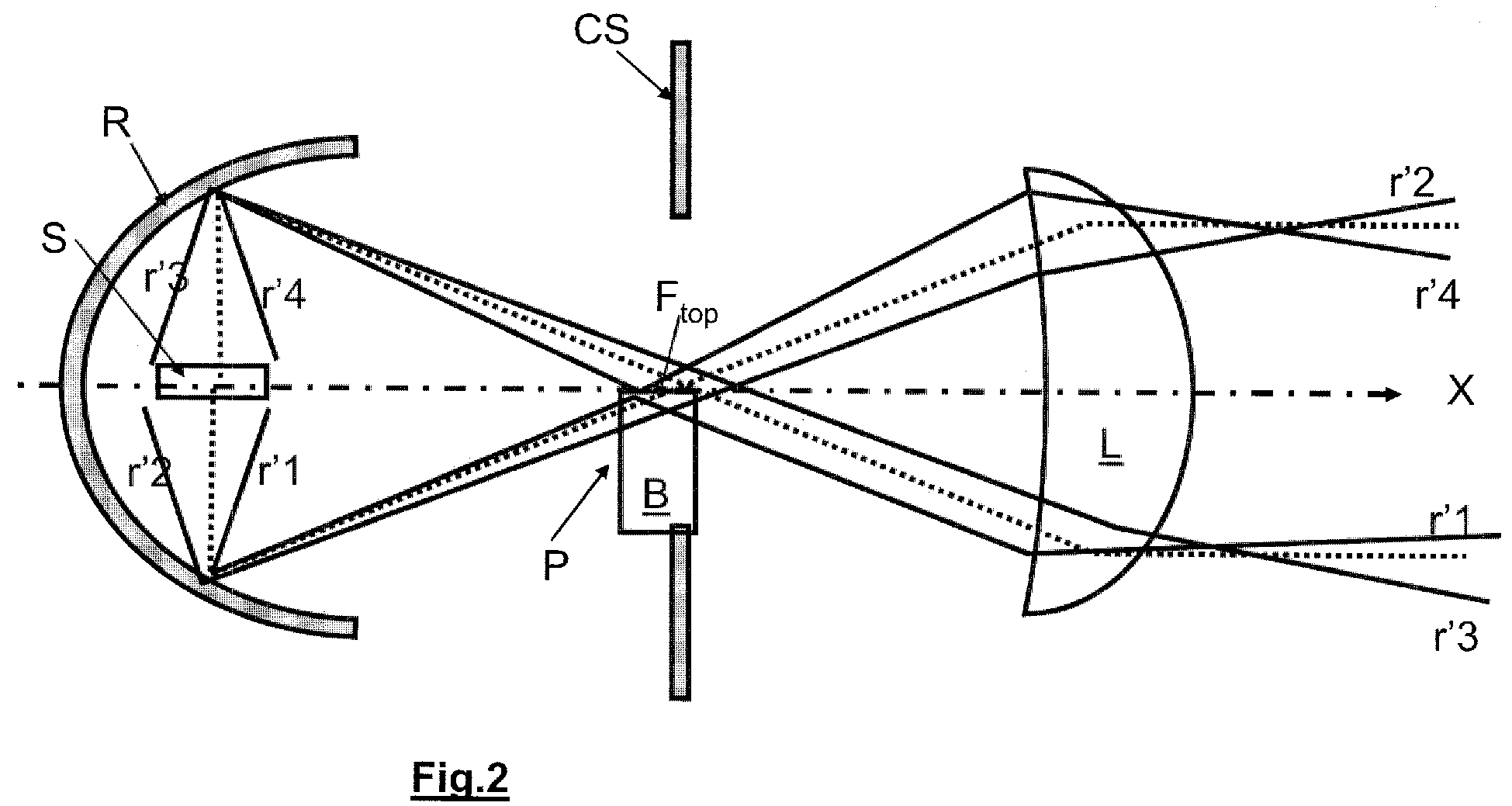
- the figure 2 is a longitudinal section of a modified elliptical road module according to the invention (in all the figures, the same references represent the same components).
- the only modification with respect to the module according to the preceding figure is the presence of an additional optical element, the folder P, in the vicinity of the second focus of the reflector R.
- This folder consists of a block B of transparent material, of parallelepiped shape , oriented perpendicularly to the optical axis X in a substantially vertical plane.
- a reflective coating Re which is here a deposit of aluminum, vacuum deposited from a thickness of less than one micron to tens of microns. Its upper face is located on the optical axis X of the module, or in its vicinity, being preferably located under the optical axis X, for example about 2 mm below the optical axis X.
- the paths of the four limit radii r'1, r'2, r'3 and r'4 have changed: the radius r'1 reaches the coating Re coming from the lower part of the reflector, it is deflected down and then returned in the lens to contribute to the lower part of the beam.
- the radius r'2 successively crosses the two side walls of the glass block B: it emerges from B in the same orientation with which it had entered.
- the radius r'4 strikes the reflective coating Re coming from the upper part of the reflector R: it is deflected upwards before passing through the lens L and contributing to the upper part of the beam.
- the radius r'3 passes over the folder P and is not affected.
- the figure 3 is an isolux of the road beam obtained with the module according to the prior art of the figure 1 : Its maximum illumination is 113 Lux at 25 meters, for a total flow of 1616 lumen.
- the maximum iso illumination curve Cmax represented on the figure 3 corresponds to a level of 64 Lux.
- the figure 4 is an isolux of the module according to the invention of the figure 2 . Its maximum illumination is 170 Lux at 25 meters for a total flow of 1610 lumens.
- the maximum illumination iso curve Cmax 'represented on the figure 4 corresponds to a level of 128 Lux.
- the folder therefore has a very beneficial effect on the maximum light intensity values of a road beam. And this advantage is much greater than the slight loss of induced flux (which is due in particular to the fact that there are losses in r'2 type rays, which pass through the glass block, and the losses also suffered by the rays deviated by the reflective coating, which is not 100% reflective but also a little absorbent).
- the figure 5 shows a variant of folder according to the invention: the wall "most downstream" of the block B relative to the optical axis X of the module is provided in the lower part of a coating B1 opacifier.
- This coating can replace, in the lower part, the static cover Cs mentioned above. It can also make it possible to improve or to adjust more precisely the light distribution of the beam.
- the figure 6 shows a second module variant according to the invention: the only difference with the variant according to the figure 2 is the fact that here the light source S is not a filament lamp but a light-emitting diode, whose emitting surface is turned in the opposite direction to that of the optical axis X: the rays emitted in a half-plane are reflected by the reflector, then some of them, either coming from above or from below, are deflected by the folder according to the same principle as figure 2 .
- the light source S is not a filament lamp but a light-emitting diode, whose emitting surface is turned in the opposite direction to that of the optical axis X: the rays emitted in a half-plane are reflected by the reflector, then some of them, either coming from above or from below, are deflected by the folder according to the same principle as figure 2 .
- the light source S is not a filament lamp but a light-emitting diode, whose emitting
- the Figures 7, 8 and 9 relate to a third module variant according to the invention: a bi-function module code / route.
- the source is a xenon lamp.
- the reflector R is a little different, including a lower part "flat" because less useful optically than in previous cases.
- a mobile cover C arranged between the folder P and the lens L, in the immediate vicinity of the folder P. The figures show it in different positions.
- the cache C (which is in fact a double cache, of approximately V-shaped section, as described for example in the patent FR 07 01290 filed on February 22, 2007 ) is in the up position, an optically active position capable of creating, according to the shape of its upper edge, the code-type cut in the beam, in a known manner (it is clear that the cache C can define any other appropriate cutoff profile).
- the reflecting surface Re of the folder P is in the immediate vicinity of the optical axis of the projector, under the upper edge of the cover C in its optically active position.
- the folder according to the invention is static, and is not secured to the cache, although in its immediate vicinity, in front of it.
- the movement of the cover is achieved by any appropriate means, in particular with the aid of an electric motor controlled by a control panel or automatically, or by any appropriate manual means.
- the bi-function module can be coupled with an automatic switching device from one type of beam to another, such as that described in the patent. FR 2,877,892 .
- the Z axis is a vertical axis, or slightly inclined to the vertical in the case of a slight inclination of the optical axis X relative to the horizontal due to a range correction performed on the module once in place on the vehicle.
- At least one of the front faces F in or rear F out of the transparent block constituting the folder P can be inclined relative to to the Z axis. More precisely, the rear face F in can be inclined towards the rear of the angle ⁇ in , and the front face F out can be inclined towards the front of the angle ⁇ out .
- angles ⁇ in and ⁇ out formed respectively by the rear faces F in and before F out with the Z axis are advantageously between 5 ° and 30 °, the angle ⁇ in being less than or equal to the angle ⁇ out .
- angles ⁇ in and ⁇ out equal to each other and to the value 17 ° are chosen, the angles ⁇ in and ⁇ out being measured from the Z axis.
- the folder P therefore constitutes a transparent block symmetrical with respect to the axis Z, hexahedron-shaped.
- the upper face F top of this volume has for example a width W top of about 6 mm, and a length D top of between 2 mm and 10 mm, and preferably equal to about 5 mm.
- the rear faces F in and front F out being inclined in this way, the length of the lower face F bottom of the folder P is lower than that D top of the upper face F top .
- the folder P then behaves like a deviating prism. In this way, some of the rays passing through the transparent block constituting the folder may be deviated to improve the quality and / or homogeneity of the light beam leaving the module.
- FIG 12 represents an isolux of the module according to the embodiment of the invention on the Figures 10A and 10B .
- the maximum illumination is 163 Lux at 25 meters for a total flow of 1610 lumens.
- the curve iso maximum illumination Cmax "shown on the figure 12 corresponds to a level of 128 Lux.
- the inclination of the faces F in and F out of the folder therefore has a very beneficial effect on the maximum light intensity values of a road beam.
- At least one of the rear faces F in and before F out of the transparent block may be curved, in particular at least partially concave, as has been represented on the figure 11C .
- the angle ⁇ out that the output face F out forms with the Z axis is greater than the angle ⁇ in which the input face F in forms with the Z axis.
- the figure 11C still represents an alternative embodiment of the transparent block constituting the folder P, in which the rear end and front end are this time curved: they are both concave, with a radius of curvature of about 35mm. Preferably, their radius of curvature is between 20 and 50 mm, in particular between 30 and 40 mm. It can also be provided that only the front face F out is concave, and that the rear face F in remains flat, in a vertical or inclined plane. The appropriate curvature of a face or faces of the transparent block makes it possible to deviate the rays in a controlled manner, as explained above.
- the lateral faces F left and F right not be parallel, but to make an angle with the axis Z.
- the lateral faces F left and F right will have the same inclination, so that that the block transparent retains symmetry with respect to a vertical plane passing through the optical axis X.
- Such a design has the advantage of not introducing a lack of homogeneity on the sides of the beam: one notices in fact on the figure 4 that a transparent parallelepipedic block such as B whose upper face has a width extending over substantially the entire width of the module transversely to the optical axis generates defects of homogeneity on the beam. More precisely, as can be seen on the figure 4 , the different isolux each have a "throttle" on either side of the optical axis X, just above the horizontal, for values of the opening angle of about 30%.
- the transparent block has an upper face whose width W top is restricted with respect to the total width of the system and reduced with respect to the width W bottom of the lower face, its main vocation being to act locally only in the vicinity of the zone of maximum concentration. It can be seen that the lateral defects described above no longer appear on the isoluxes of the figure 12 .
Landscapes
- Engineering & Computer Science (AREA)
- General Engineering & Computer Science (AREA)
- Physics & Mathematics (AREA)
- Microelectronics & Electronic Packaging (AREA)
- Optics & Photonics (AREA)
- Non-Portable Lighting Devices Or Systems Thereof (AREA)
Abstract
La présente invention concerne un module optique (M) pour dispositif d'éclairage de véhicule automobile comprenant :
- un réflecteur (R) définissant un axe optique (X),
- un élément dioptrique (L),
- une source lumineuse (S) disposée entre le réflecteur et l'élément dioptrique,
- une plieuse (P) disposée entre la source et l'élément dioptrique et comportant un bloc transparent (B) dont la face supérieure (Ftop) est parallèle à l'axe optique (X) et est munie au moins partiellement d'un revêtement réfléchissant (Re).
a reflector (R) defining an optical axis (X),
a dioptric element (L),
a light source (S) arranged between the reflector and the dioptric element,
a folder (P) arranged between the source and the dioptric element and comprising a transparent block (B) whose upper face (F top ) is parallel to the optical axis (X) and is provided at least partially with a reflective coating (Re).
Description
La présente invention a pour objet un module optique pour dispositif d'éclairage automobile du type projecteur. Elle s'applique plus particulièrement aux modules optiques appelés modules elliptiques comprenant une source de lumière associée à un réflecteur et fermé par un élément dioptrique du type lentille convergente, par exemple une lentille de type plan-convexe, lentille de Fresnel. L'invention s'intéresse aussi aux modules optiques équipés d'un cache fixe ou mobile apte à intercepter au moins partiellement, selon sa position, le faisceau lumineux émis par l'ensemble source lumineuse/réflecteur. La forme du bord supérieur du cache permet de délimiter la coupure voulue dans le faisceau par imagerie avec la lentille convergente.The present invention relates to an optical module for automobile lighting device of the projector type. It applies more particularly to optical modules called elliptical modules comprising a light source associated with a reflector and closed by a dioptric element of the convergent lens type, for example a plano-convex lens, Fresnel lens. The invention is also concerned with optical modules equipped with a fixed or movable cover able to intercept at least partially, depending on its position, the light beam emitted by the light source / reflector assembly. The shape of the upper edge of the cache makes it possible to define the desired cut in the beam by imaging with the convergent lens.
Pour plus de détails sur les modules à cache mobile, on peut notamment se reporter aux brevets
Il est déjà connu du brevet
L'invention a pour but un module optique, par exemple un module elliptique, qui offre des performances optiques améliorées, et plus particulièrement des performances améliorées dans le cadre de l'émission d'un faisceau sans coupure de type route.The aim of the invention is an optical module, for example an elliptical module, which offers improved optical performance, and more particularly improved performance in the context of the emission of an uninterrupted beam of the road type.
L'invention a tout d'abord pour objet un module optique pour dispositif d'éclairage de véhicule automobile comprenant
- un réflecteur définissant un axe optique,
- un élément dioptrique,
- une source lumineuse disposée entre le réflecteur et l'élément dioptrique,
- une plieuse disposée entre la source et l'élément dioptrique et comportant un bloc transparent dont la face supérieure est munie au moins partiellement d'un revêtement réfléchissant.
- a reflector defining an optical axis,
- a dioptric element,
- a light source arranged between the reflector and the dioptric element,
- a folder disposed between the source and the dioptric element and having a transparent block whose upper face is provided at least partially with a reflective coating.
Dans la présente description, on appellera « transparent » un bloc qui peut être traversé par des rayons lumineux. Ce bloc peut ainsi être en verre, ou être en plastique transparent, le choix se faisant notamment en prenant en compte les contraintes thermiques régnant dans le module (différentes selon le type de source lumineuse utilisée). Un tel bloc transparent peut ainsi :
- soit ne pas perturber de façon significative la direction ou l'intensité des rayons qui le traversent, quand il est constitué par exemple d'un parallélépipède,
- soit au contraire imposer une déviation prédéterminée à ces rayons, de manière à ce qu'ils soient dirigés vers des zones particulières du faisceau lumineux émergeant du module.
- either does not significantly disturb the direction or the intensity of the rays passing through it, when it consists for example of a parallelepiped,
- or rather to impose a predetermined deviation to these rays, so that they are directed to particular areas of the light beam emerging from the module.
On comprend par « revêtement réfléchissant » une couche réfléchissante qui peut être déposée, par exemple par une technique de dépôt sous vide, sur la face supérieure du bloc transparent, ou qui peut être rapportée sur cette face par tout moyen. (Ce revêtement est avantageusement réfléchissant sur au moins une de ses faces, notamment sa face supérieure une fois la plieuse en position de montage, et notamment réfléchissant sur ses deux faces.)By "reflective coating" is meant a reflective layer which can be deposited, for example by a vacuum deposition technique, on the upper face of the transparent block, or which can be attached to this face by any means. (This coating is advantageously reflecting on at least one of its faces, particularly its upper face once the folder in the mounting position, and in particular reflecting on both sides.)
L'invention propose ici une nouvelle conception de « plieuse » qui est très avantageuse : la partie « active » de la plieuse, c'est-à-dire le revêtement réfléchissant, étant soutenue par ce bloc transparent qui n'interfère pas, ou très peu, avec les rayons lumineux émis par la source, ou au contraire qui interfère de manière contrôlée avec ces rayons, on peut éliminer les effets parasites d'un support qui serait, par exemple, en métal.The invention proposes here a new design of "folding" which is very advantageous: the "active" part of the folder, that is to say the reflective coating, being supported by this transparent block which does not interfere, or very little, with the light rays emitted by the source, or on the contrary which interferes in a controlled manner with these rays, one can eliminate the parasitic effects of a support which would be, for example, of metal.
De préférence, le module optique est destiné à émettre au moins un faisceau sans coupure de type route, la face supérieure de la plieuse déviant vers le haut au moins certains des rayons émis par la source et/ou réfléchis par le réflecteur afin d'accroître l'intensité maximale dudit faisceau. Le module peut donc être simplement un module mono fonction : un module route seulement.Preferably, the optical module is intended to emit at least one road-type uninterrupted beam, the upper face of the deflecting bender upwards at least some of the rays emitted by the source and / or reflected by the reflector in order to increase the maximum intensity of said beam. The module can therefore be simply a single function module: a road module only.
C'est dans le contexte de l'émission d'un faisceau route que ce type de plieuse est en effet très intéressant, puisque le bloc transparent support :
- soit n'intercepte quasiment pas la lumière, et ne crée pas de coupure involontaire,
- soit dévie de manière contrôlée les rayons lumineux qui le traversent de manière à ce qu'ils apportent une contribution à des zones prédéterminées du faisceau route.
- or almost does not intercept the light, and does not create an involuntary break,
- or deviates in a controlled manner light rays that pass through it so that they make a contribution to predetermined areas of the road beam.
C'est aussi dans ce contexte que son utilisation est la plus inattendue : en effet, c'est dans une configuration route que la conception d'un module est la plus simple : il n'est pas besoin d'utiliser un cache pour faire une coupure. Or ici on a quand même ajouté cette plieuse, et il s'est avéré, de façon surprenante, que sa présence avait un impact très positif sur la valeur d'intensité maximale obtenue dans le faisceau.It is also in this context that its use is the most unexpected: indeed, it is in a road configuration that the design of a module is the simplest: there is no need to use a cache to make a cut. But here we still added this folder, and it turned out, surprisingly, that its presence had a very positive impact on the value of maximum intensity obtained in the beam.
De préférence, le bloc transparent est disposé substantiellement perpendiculairement à l'axe optique du module, symétriquement par rapport à cet axe.Preferably, the transparent block is disposed substantially perpendicular to the optical axis of the module, symmetrically with respect to this axis.
Selon une variante, au moins une partie d'au moins une des parois latérales droite, gauche, avant ou arrière du bloc transparent est rendue opaque, ou diffusante, notamment par métallisation locale ou par dépoli ou par association avec un élément occultant. On choisit de préférence, dans cette variante, d'opacifier plutôt le bloc dans la partie inférieure d'au moins une des faces latérales, droite, gauche, avant et arrière : cette opération a pour but, éventuellement, de remplacer un cache statique, parfois présent même pour faire des faisceaux route, afin de les délimiter nettement.According to a variant, at least a portion of at least one of the right, left, front or rear side walls of the transparent block is made opaque, or diffusing, in particular by local metallization or by frosting or by association with an occulting element. In this variant, it is preferable to opacify rather the block in the lower part of at least one of the lateral, right, left, front and rear faces: this operation is intended, if necessary, to replace a static mask, sometimes present even to make road beams, in order to delimit them clearly.
Le bloc transparent peut avoir des parois latérales droite, gauche, avant et arrière parallèles entre elles : c'est son mode de réalisation le plus simple. On peut ainsi avoir un bloc qui est simplement substantiellement sous la forme d'un parallélépipède. On peut aussi avoir un bloc dont au moins une de ses parois latérales est courbe. Dans ce cas là, et contrairement à ce qui a été énoncé précédemment, on va modifier la forme de la paroi de façon à ce que le bloc transparent puisse jouer un rôle optique, à la manière d'une lentille, et notamment influencer la répartition photométrique du faisceau émis par le module.The transparent block may have right, left, front and rear side walls parallel to each other: this is its simplest embodiment. One can thus have a block which is simply substantially in the form of a parallelepiped. One can also have a block of which at least one of its side walls is curved. In this case, and contrary to what was stated previously, we will change the shape of the wall so that the transparent block can play an optical role, in the manner of a lens, and in particular influence the photometric distribution of the beam emitted by the module.
Le bloc transparent peut également avoir une forme d'hexaèdre, c'est-à-dire de polyèdre à six faces, dont le volume est délimité par deux faces rectangulaires parallèles et de quatre faces latérales trapézoïdales.The transparent block may also have a hexahedron shape, that is to say six-sided polyhedron, whose volume is delimited by two parallel rectangular faces and four trapezoidal lateral faces.
Le bloc transparent peut avoir une face supérieure plane : c'est son mode de réalisation le plus simple. Mais on peut aussi envisager qu'elle soit courbe au moins localement, notamment selon la longueur Là encore, c'est un paramètre sur lequel on peut jouer pour influencer sur la répartition photométrique du faisceau émis.The transparent block may have a flat upper face: this is its simplest embodiment. But it can also be envisaged that it is at least locally curved, especially along length. Again, this is a parameter that can be used to influence the photometric distribution of the emitted beam.
Selon une variante, le module est un module multi-, notamment bi fonctions. Dans ce cas, il comprend également un cache, qui est disposé entre la plieuse et l'élément dioptrique : le cache est notamment monté mobile entre au moins une position active optiquement et une position escamotée. La position active optiquement du cache correspond à l'émission par le module d'un faisceau à coupure, notamment de type code, et sa position escamotée correspond à l'émission par le module d'un faisceau sans coupure, notamment de type route. Il peut alors être préférable que le cache soit apte à rendre la plieuse au moins partiellement inefficace optiquement quand il est en position optiquement active.According to one variant, the module is a multi-module, in particular two functions. In this case, it also comprises a cover, which is arranged between the folder and the dioptric element: the cover is in particular mounted movably between at least one optically active position and a retracted position. The optically active position of the cache corresponds to the emission by the module of a cut-off beam, in particular of the code type, and its retracted position corresponds to the emission by the module of an uninterrupted beam, in particular of the road type. It may then be preferable that the cover be able to make the folder at least partially ineffective optically when it is in the optically active position.
On comprend par « position active optiquement » une position du cache telle qu'il intercepte une partie des rayons émis directement par la source ou réfléchis par le réflecteur.An "optically active position" is understood to mean a position of the cache such that it intercepts a portion of the rays emitted directly by the source or reflected by the reflector.
On comprend par « plieuse inefficace optiquement » le fait
- que le cache puisse soit intercepter les rayons réfléchis par la plieuse, notamment en étant disposé devant elle et en ayant un bord supérieur plus haut que les points les plus hauts de la face supérieure de la plieuse,
- et/ou que la configuration cache /plieuse soit telle que les rayons réfléchis par la plieuse et qui ne seraient pas interceptés par le cache constituent un apport négligeable dans la constitution du faisceau émis par le module, notamment parce que les rayons réfléchis par la plieuse sont « perdus », c'est-à-dire qu'ils passent au dessus du cache mais n'entrent pas ensuite dans l'élément dioptrique (car trop « hauts »), et/ou parce qu'ils entrent dans l'élément dioptrique mais qu'ils en ressortent de façon diffuse, étant défocalisés par rapport à l'élément dioptrique, se retrouvant notamment dans la partie inférieure du faisceau du module et n'en constituant qu'un apport minime).
- that the cache can intercept the rays reflected by the folder, in particular by being arranged in front of it and having an upper edge higher than the highest points of the upper face of the folder,
- and / or that the cache / bender configuration is such that the rays reflected by the folder and which are not intercepted by the cover constitute a negligible contribution in the constitution of the beam emitted by the module, in particular because the rays reflected by the folder are "lost", that is to say they pass over the cache but do not enter the dioptric element (because too "high"), and / or because they enter the dioptric element but that they emerge in a diffuse way, being defocused by relative to the dioptric element, found in particular in the lower part of the beam of the module and constituting only a minimal contribution).
De même, on comprend par « plieuse partiellement inefficace optiquement » le fait que, lorsque le cache est en position active optiquement, ce dernier n'intercepte que partiellement les rayons réfléchis par la surface réfléchissante de la plieuse, les rayons qui ne sont pas interceptés par le cache et qui ne sont pas « perdus » contribuant à augmenter les performances du faisceau à coupure, et notamment sa portée.Similarly, it is understood by "partially optically inefficient folder" that when the cover is optically active position, it only partially intercepts the rays reflected by the reflective surface of the folder, the rays that are not intercepted by the cache and which are not "lost" contributing to increase the performance of the cut-off beam, and in particular its range.
Pour ce faire, une possibilité est que le cache ait, en position optiquement active, son bord supérieur à une hauteur telle par rapport à celle de la face supérieure du bloc de la plieuse qu'elle intercepte une partie des rayons réfléchis par la face supérieure du revêtement réfléchissant de celle-ci.To do this, one possibility is that the cover has, in the optically active position, its upper edge at a height such as that of the upper face of the block of the folder that it intercepts a part of the rays reflected by the upper face. reflective coating thereof.
L'élément dioptrique est notamment une lentille.The dioptric element is in particular a lens.
La source lumineuse équipant le module peut être une lampe à filament, ou une lampe à arc de type xénon, ou encore une diode électroluminescente ou un groupe de diodes électroluminescentes.The light source equipping the module may be a filament lamp, or a xenon arc lamp, or a light emitting diode or a group of light emitting diodes.
L'invention a également pour objet un projecteur pour véhicule automobile qui comprend un module optique tel que décrit plus haut.The invention also relates to a motor vehicle headlight which comprises an optical module as described above.
L'invention sera détaillée en se référant à la description ci-dessous d'exemples de réalisation non limitatifs et aux figures en annexe qui les illustrent :
- La
figure 1 est une représentation schématique un module elliptique mono fonction destiné à émettre un faisceau de type route selon l'art antérieur - La
figure 2 est une représentation schématique un module elliptique mono fonction destiné à émettre un faisceau de type route selon une première variante de l'invention, - Les
figures 3 sont les représentations simplifiées des isolux des faisceaux route obtenus respectivement par le module selon laet 4figure 1 et par le module selon lafigure 2 - La
figure 5 est une représentation d'une autre de plieuse selon l'invention. - La
figure 6 est une représentation schématique d'un module elliptique mono fonction destiné à émettre un faisceau de type route selon une seconde variante de l'invention, - Les
figures 7, 8 et 9 sont des représentations schématiques un module elliptique bi fonction destiné à émettre un faisceau de type code et de type route, selon une troisième variante de l'invention, - les
figures 10A et 10B sont des représentations schématiques en perspective d'une variante de plieuses selon l'invention, - les
figures 11A, 11B et 11C sont des représentations schématiques en coupe longitudinale par un plan vertical contenant l'axe optique du module elliptique d'autres variantes de plieuses selon l'invention, et - la
figure 12 est une représentation simplifiée des isolux du faisceau route obtenu par le module équipé de la plieuse selon lesfigures 10A et 10B .
- The
figure 1 is a schematic representation of a single-function elliptical module intended to emit a road-type beam according to the prior art - The
figure 2 is a schematic representation of a single-function elliptical module for emitting a road-type beam according to a first variant of the invention, - The
Figures 3 and 4 are the simplified representations of the isolux of the route beams obtained respectively by the module according to thefigure 1 and by the module according to thefigure 2 - The
figure 5 is a representation of another folder according to the invention. - The
figure 6 is a schematic representation of a single-function elliptical module for emitting a road-type beam according to a second variant of the invention, - The
Figures 7, 8 and 9 schematic representations of an elliptical module bi function intended to emit a code-type beam and of the road type, according to a third variant of the invention, - the
Figures 10A and 10B are diagrammatic representations in perspective of a variant of folders according to the invention, - the
Figures 11A, 11B and 11C are diagrammatic representations in longitudinal section through a vertical plane containing the optical axis of the elliptical module of other variants of folders according to the invention, and - the
figure 12 is a simplified representation of the isolux of the road beam obtained by the module equipped with the folder according to theFigures 10A and 10B .
Toutes ces figures sont volontairement très schématiques, très simples et pas nécessairement à l'échelle pour en faciliter la lecture.All these figures are deliberately very schematic, very simple and not necessarily scaled to facilitate reading.
On comprend dans tout le présent texte les termes « avant », « arrière », « haut », « bas », « supérieur » ou « inférieur » d'après la position du module une fois intégré éventuellement dans un projecteur et monté sur un véhicule en mode de fonctionnement normal. On rappelle que le module est disposé, une fois monté dans le projecteur puis dans le véhicule, et tel que représenté aux figures suivantes, de façon à ce que son axe optique soit contenu dans un plan sensiblement horizontal (sensiblement, car le module peut être réglé, en effet, de façon à ce que son axe optique soit légèrement incliné, notamment vers le bas, de moins de 2°).The term "front", "back", "up", "down", "upper" or "lower" is understood throughout the present text according to the position of the module once integrated, possibly in a projector, and mounted on a vehicle in normal operating mode. It is recalled that the module is arranged, once mounted in the projector and then in the vehicle, and as shown in the following figures, so that its optical axis is contained in a substantially horizontal plane (substantially, because the module can be adjusted, in fact, so that its optical axis is slightly inclined, especially downwards, less than 2 °).
De même, on comprend dans tout le présent texte par « longueur », une dimension mesurée suivant l'axe optique, « largeur » une dimension mesurée horizontalement perpendiculairement à l'axe optique, et « hauteur » une dimension mesurée verticalement perpendiculairement à l'axe optiqueSimilarly, throughout the present text, "length" means a dimension measured along the optical axis, "width" is a dimension measured horizontally perpendicular to the optical axis, and "height" is a dimension measured vertically perpendicular to the optical axis. optical axis
Par exemple, sur les
En référence à la
Les rayons lumineux r1, r2, r3, r4 émis par la source lumineuse S sont envoyés en direction de la lentille L soit directement, soit après réflexion sur la paroi du réflecteur R. Les rayons émergeant de la lentille L forment alors un faisceau lumineux. Les rayons représentés en pointillés sont les rayons moyens passant par le second foyer du réflecteur.The light rays r1, r2, r3, r4 emitted by the light source S are sent towards the lens L either directly or after reflection on the wall of the reflector R. The rays emerging from the lens L then form a light beam. The rays represented in dotted lines are the average radii passing through the second focus of the reflector.
Ici, puisqu'il s'agit de faire un faisceau route, il n'y a aucun élément occultant de type cache apte à faire une coupure. Est cependant représenté, de façon connue, un cache statique Cs qui est un cadre permettant de délimiter avec netteté et précision la forme du faisceau sans coupure.Here, since it is a question of making a road beam, there is no concealing element of type cache able to make a break. However, is represented, in known manner, a static cover Cs which is a frame for delimiting with clarity and precision the shape of the unbroken beam.
La
Les trajets des quatre rayons limites r'1, r'2, r'3 et r'4 ont changé : le rayon r'1 atteint le revêtement Re en venant de la partie inférieure du réflecteur, il est dévié vers le bas puis rentre dans la lentille pour contribuer à la partie basse du faisceau. Le rayon r'2 traverse successivement les deux parois latérales du bloc en verre B : il ressort de B dans la même orientation avec laquelle il y était entré. Le rayon r'4 frappe le revêtement réfléchissant Re en provenant de la partie supérieure du réflecteur R : il est dévié vers le haut avant de traverser la lentille L et contribuer à la partie haute du faisceau. Le rayon r'3 passe au dessus de la plieuse P et n'est donc pas affecté.The paths of the four limit radii r'1, r'2, r'3 and r'4 have changed: the radius r'1 reaches the coating Re coming from the lower part of the reflector, it is deflected down and then returned in the lens to contribute to the lower part of the beam. The radius r'2 successively crosses the two side walls of the glass block B: it emerges from B in the same orientation with which it had entered. The radius r'4 strikes the reflective coating Re coming from the upper part of the reflector R: it is deflected upwards before passing through the lens L and contributing to the upper part of the beam. The radius r'3 passes over the folder P and is not affected.
La
La
On déduit de la comparaison de ces valeurs que l'intensité maximale du faisceau selon l'invention est augmentée de 50%, sans perte de flux significative.It is deduced from the comparison of these values that the maximum intensity of the beam according to the invention is increased by 50% without significant loss of flux.
La plieuse a donc un effet très bénéfique sur les valeurs d'intensité lumineuse maximales d'un faisceau route. Et cet avantage est bien supérieur à la légère perte de flux induite (qui est notamment due au fait qu'il y a des pertes dans les rayons de type r'2, qui traversent le bloc en verre, et aux pertes également subies par les rayons déviés par le revêtement réfléchissant, qui n'est pas réfléchissant à 100% mais également un peu absorbant).The folder therefore has a very beneficial effect on the maximum light intensity values of a road beam. And this advantage is much greater than the slight loss of induced flux (which is due in particular to the fact that there are losses in r'2 type rays, which pass through the glass block, and the losses also suffered by the rays deviated by the reflective coating, which is not 100% reflective but also a little absorbent).
La
La
Les
A la
En position haute, on voit de la
- soit tendent à « se perdre » au dessus de la lentille L,
- soit contribuent au renforcement du faisceau.
- either tend to "get lost" above the L lens,
- either contribute to strengthening the beam.
Ainsi, quand le cache C est en position active, de par sa configuration relativement à la plieuse il la rend partiellement inefficace optiquement.Thus, when the cover C is in the active position, because of its configuration relative to the folder, it renders it partially ineffective optically.
Les
- soit, comme représenté à la
figure 8 , le cache C est basculé selon un axe de rotation non représenté qui est sensiblement horizontal et perpendiculaire à l'axe optique X, - soit, comme représenté à la
figure 9 , le cache C est abaissé, dans un mouvement de translation dans un plan sensiblement vertical et perpendiculaire à l'axe optique X.
- either, as shown in
figure 8 , the cover C is pivoted along an axis of rotation, not shown, which is substantially horizontal and perpendicular to the optical axis X, - either, as shown in
figure 9 , the cover C is lowered, in a translation movement in a substantially vertical plane and perpendicular to the optical axis X.
Dans les deux cas, dans cette position escamotée, il ne joue plus de rôle optique significatif, il ne peut plus créer de coupure : on obtient un faisceau de type route.In both cases, in this retracted position, it no longer plays a significant optical role, it can no longer create a cutoff: a road-type beam is obtained.
On note que dans cette variante de module bi fonction, la plieuse selon l'invention est statique, et n'est pas solidarisée au cache, bien qu'à son voisinage immédiat, devant celui-ci.Note that in this variant of dual function module, the folder according to the invention is static, and is not secured to the cache, although in its immediate vicinity, in front of it.
Le déplacement du cache est réalisé par tout moyen approprié, notamment à l'aide d'un moteur électrique piloté par une commande du tableau de bord ou de façon automatique, ou encore par tout moyen manuel approprié.The movement of the cover is achieved by any appropriate means, in particular with the aid of an electric motor controlled by a control panel or automatically, or by any appropriate manual means.
Également, le module bi fonction peut être couplé avec un dispositif de commutation automatique d'un type de faisceau à un autre, comme par exemple celui qui est décrit dans le brevet
On a représenté sur les
- Fin pour la face arrière par laquelle la lumière pénètre dans la plieuse P,
- Fout pour la face avant par laquelle émerge la lumière,
- Ftop pour la face supérieure pourvue du revêtement réfléchissant Re,
- Fbottom pour la face inférieure opposée à la face Ftop,
- Fright et Fleft pour les faces latérales de la plieuse P.
- Wtop est la largeur de la face supérieure Ftop, mesurée perpendiculairement à l'axe optique X,
- Wbottom est la largeur de la face inférieure Fbottom, mesurée perpendiculairement à l'axe optique X,
- Dtop est la longueur de la face supérieure Ftop, mesurée parallèlement à l'axe optique X, et représentant l'épaisseur de la plieuse P,
- L'axe Z est un axe perpendiculaire à l'axe optique X,
- αin est l'angle que forme la face d'entrée Fin avec l'axe Z, et
- αout est l'angle que forme la face de sortie Fout avec l'axe Z.
- F in for the rear face through which the light enters the folder P,
- F out for the front side through which emerges the light,
- F top for the upper side provided with the reflective coating Re,
- F bottom for the bottom face opposite the F top face,
- F right and F left for the side faces of the folder P.
- W top is the width of the top face F top , measured perpendicularly to the optical axis X,
- W bottom is the width of the bottom face F bottom , measured perpendicular to the optical axis X,
- D top is the length of the top face F top , measured parallel to the optical axis X, and representing the thickness of the folder P,
- The Z axis is an axis perpendicular to the optical axis X,
- α in is the angle formed by the input face F in with the axis Z, and
- α out is the angle formed by the output face F out with the Z axis.
L'axe Z est un axe vertical, ou légèrement incliné sur la verticale dans le cas d'une légère inclinaison de l'axe optique X par rapport à l'horizontale dûe à une correction de portée réalisée sur le module une fois en place sur le véhicule.The Z axis is a vertical axis, or slightly inclined to the vertical in the case of a slight inclination of the optical axis X relative to the horizontal due to a range correction performed on the module once in place on the vehicle.
On voit sur les
Les angles αin et αout que forment respectivement les faces arrière Fin et avant Fout avec l'axe Z sont avantageusement compris entre 5° et 30°, l'angle αin étant inférieur ou égal à l'angle αout.The angles α in and α out formed respectively by the rear faces F in and before F out with the Z axis are advantageously between 5 ° and 30 °, the angle α in being less than or equal to the angle α out .
Dans un mode de réalisation représenté sur les
Dans ce mode de réalisation, la plieuse P constitue donc un bloc transparent symétrique par rapport à l'axe Z, en forme d'hexaèdre. La face supérieure Ftop de ce volume a par exemple une largeur Wtop d'environ 6mm, et une longueur Dtop comprise entre 2mm et 10mm, et de préférence égale à environ 5 mm.In this embodiment, the folder P therefore constitutes a transparent block symmetrical with respect to the axis Z, hexahedron-shaped. The upper face F top of this volume has for example a width W top of about 6 mm, and a length D top of between 2 mm and 10 mm, and preferably equal to about 5 mm.
Les faces arrière Fin et avant Fout étant inclinées de cette façon, la longueur de la face inférieure Fbottom de la plieuse P est inférieure à celle Dtop de la face supérieure Ftop. La plieuse P se comporte alors comme un prisme déviateur. De cette manière, certains des rayons traversant le bloc transparent constituant la plieuse peuvent être pour déviés améliorer la qualité et/ou l'homogénéité du faisceau lumineux sortant du module.The rear faces F in and front F out being inclined in this way, the length of the lower face F bottom of the folder P is lower than that D top of the upper face F top . The folder P then behaves like a deviating prism. In this way, some of the rays passing through the transparent block constituting the folder may be deviated to improve the quality and / or homogeneity of the light beam leaving the module.
On a ainsi observé que, en utilisant un bloc transparent à faces parallèles entre elles et verticales, comme représenté à la
En inclinant de façon appropriée au moins une des faces arrière Fin ou avant Fout du bloc transparent, comme représenté notamment sur les
C'est ce que l'on constate sur la
On déduit de la comparaison de ces valeurs avec celles de la
L'inclinaison des faces Fin et Fout de la plieuse a donc un effet très bénéfique sur les valeurs d'intensité lumineuse maximales d'un faisceau route.The inclination of the faces F in and F out of the folder therefore has a very beneficial effect on the maximum light intensity values of a road beam.
Le même effet peut être obtenu avec des angles αin entre la face d'entrée Fin et l'axe Z, et αout entre la face de sortie Fout et l'axe Z inégaux, en choisissant de préférence αin inférieur ou égal à αout.The same effect can be obtained with angles α in between the input face F in and the Z axis, and α out between the output face F out and the unequal axis Z, preferably choosing α in lower or equal to α out .
Alternativement, l'une au moins des faces arrière Fin et avant Fout du bloc transparent peut être courbe, notamment au moins partiellement concave, ainsi qu'on l'a représenté sur le
Selon encore un autre mode de réalisation, l'angle αout que forme la face de sortie Fout avec l'axe Z est supérieur à l'angle αin que forme la face d'entrée Fin avec l'axe Z. On peut par exemple prévoir que αin = 5° et αout = 20°. En effet, on a constaté que c'est l'inclinaison de la face avant Fout du bloc transparent qui est la plus efficace pour dévier les rayons de façon contrôlée, et que la face arrière Fin peut donc avoir une inclinaison moindre, ou même être simplement dans un plan vertical comme dans le premier mode de réalisation des
La
Des variantes et d'autre modes de construction sont encore possibles.Variants and other modes of construction are still possible.
On peut par exemple prévoir que les faces latérales Fleft et Fright ne soient pas parallèles, mais fassent chacune un angle avec l'axe Z. De préférence, les faces latérales Fleft et Fright auront la même inclinaison, de manière à ce que le bloc transparent conserve une symétrie par rapport à un plan vertical passant par l'axe optique X.For example, it is possible for the lateral faces F left and F right not to be parallel, but to make an angle with the axis Z. Preferably, the lateral faces F left and F right will have the same inclination, so that that the block transparent retains symmetry with respect to a vertical plane passing through the optical axis X.
On pourra par exemple prévoir que la largeur Wbottom de la face inférieure Fbottom soit supérieure ou égale à largeur Wtop de la face supérieure Ftop, en prenant par exemple pour valeurs Wtop = environ 6 mm, et Wbottom = environ 14 mm.For example, it is possible to provide that the width W bottom of the bottom face F bottom is greater than or equal to width W top of the top face F top , taking for example values W top = about 6 mm, and W bottom = about 14 mm.
Une telle conception présente comme avantage de ne pas introduire de défaut d'homogénéité sur les côtés du faisceau : on remarque en effet sur la
De tels « creux » latéraux dans le faisceau sont visibles en présence d'obstacles sur les côtés de la route et présentent donc une gêne pour le conducteur. Dans son mode de réalisation préféré, représenté sur les
Claims (19)
Applications Claiming Priority (1)
| Application Number | Priority Date | Filing Date | Title |
|---|---|---|---|
| FR0704332A FR2917484B1 (en) | 2007-06-18 | 2007-06-18 | OPTICAL MODULE FOR AUTOMOTIVE LIGHTING DEVICE |
Publications (2)
| Publication Number | Publication Date |
|---|---|
| EP2006604A1 true EP2006604A1 (en) | 2008-12-24 |
| EP2006604B1 EP2006604B1 (en) | 2010-06-16 |
Family
ID=38578704
Family Applications (1)
| Application Number | Title | Priority Date | Filing Date |
|---|---|---|---|
| EP08158436A Active EP2006604B1 (en) | 2007-06-18 | 2008-06-17 | Optical module for vehicular lighting device |
Country Status (4)
| Country | Link |
|---|---|
| EP (1) | EP2006604B1 (en) |
| AT (1) | ATE471487T1 (en) |
| DE (1) | DE602008001530D1 (en) |
| FR (1) | FR2917484B1 (en) |
Cited By (2)
| Publication number | Priority date | Publication date | Assignee | Title |
|---|---|---|---|---|
| EP2302292A1 (en) * | 2009-09-29 | 2011-03-30 | Valeo Vision | Optical module with folder formed by a transparent material/air dioptre |
| CN105588061A (en) * | 2016-02-29 | 2016-05-18 | 上海小糸车灯有限公司 | Low-high beam integrated light-emitting diode PES unit of automotive headlamp |
Families Citing this family (3)
| Publication number | Priority date | Publication date | Assignee | Title |
|---|---|---|---|---|
| FR2962785B1 (en) * | 2010-07-19 | 2014-11-21 | Valeo Vision | PLYWOOD ON TRANSPARENT BLADE WITH FILE |
| FR2962784B1 (en) | 2010-07-19 | 2015-01-16 | Valeo Vision | REFLECTOR OF THE ELLIPTICAL TYPE CORRECTED |
| CN110553213B (en) * | 2018-06-01 | 2022-01-07 | 深圳市绎立锐光科技开发有限公司 | Light source module |
Citations (10)
| Publication number | Priority date | Publication date | Assignee | Title |
|---|---|---|---|---|
| US4914747A (en) * | 1988-06-28 | 1990-04-03 | Koito Seisakusho Co, Ltd. | Vehicular headlamp |
| FR2754039A1 (en) | 1996-10-02 | 1998-04-03 | Valeo Vision | ELLIPTICAL GENERATOR PROJECTOR FOR A MOTOR VEHICLE HAVING AN IMPROVED CUTTING COVER, AND METHOD OF MANUFACTURING THE CACHE |
| US5938323A (en) * | 1996-05-24 | 1999-08-17 | Cooper Automotive Products, Inc. | Projector light assembly |
| EP1197387A1 (en) | 2000-10-12 | 2002-04-17 | Valeo Vision | Motor vehicle headlamp comprising an adjustable shade |
| EP1422471A2 (en) | 2002-11-21 | 2004-05-26 | Valeo Vision | Elliptical vehicle headlamp emitting different light beams |
| EP1442472A2 (en) | 2001-11-05 | 2004-08-04 | Shimadzu Research Laboratory (Europe) Ltd. | A quadrupole ion trap device and methods of operating a quadrupole ion trap device |
| WO2005100088A2 (en) * | 2004-04-08 | 2005-10-27 | Federal-Mogul Corporation | Projector lamp headlight with chromatic aberration correction |
| FR2877892A1 (en) | 2004-11-18 | 2006-05-19 | Valeo Vision Sa | Headlamp`s automatic commutation controlling method for motor vehicle, involves processing images for detecting traffic condition to commute headlamps from high beam state to low beam state, and controlling headlamps to low beam state |
| EP1746340A2 (en) | 2005-07-21 | 2007-01-24 | Valeo Vision | Optical module for a motor vehicle lighting device |
| FR2913094A1 (en) | 2007-02-22 | 2008-08-29 | Valeo Vision Sa | PROJECTOR FOR MOTOR VEHICLE. |
-
2007
- 2007-06-18 FR FR0704332A patent/FR2917484B1/en not_active Expired - Fee Related
-
2008
- 2008-06-17 EP EP08158436A patent/EP2006604B1/en active Active
- 2008-06-17 DE DE602008001530T patent/DE602008001530D1/en active Active
- 2008-06-17 AT AT08158436T patent/ATE471487T1/en not_active IP Right Cessation
Patent Citations (10)
| Publication number | Priority date | Publication date | Assignee | Title |
|---|---|---|---|---|
| US4914747A (en) * | 1988-06-28 | 1990-04-03 | Koito Seisakusho Co, Ltd. | Vehicular headlamp |
| US5938323A (en) * | 1996-05-24 | 1999-08-17 | Cooper Automotive Products, Inc. | Projector light assembly |
| FR2754039A1 (en) | 1996-10-02 | 1998-04-03 | Valeo Vision | ELLIPTICAL GENERATOR PROJECTOR FOR A MOTOR VEHICLE HAVING AN IMPROVED CUTTING COVER, AND METHOD OF MANUFACTURING THE CACHE |
| EP1197387A1 (en) | 2000-10-12 | 2002-04-17 | Valeo Vision | Motor vehicle headlamp comprising an adjustable shade |
| EP1442472A2 (en) | 2001-11-05 | 2004-08-04 | Shimadzu Research Laboratory (Europe) Ltd. | A quadrupole ion trap device and methods of operating a quadrupole ion trap device |
| EP1422471A2 (en) | 2002-11-21 | 2004-05-26 | Valeo Vision | Elliptical vehicle headlamp emitting different light beams |
| WO2005100088A2 (en) * | 2004-04-08 | 2005-10-27 | Federal-Mogul Corporation | Projector lamp headlight with chromatic aberration correction |
| FR2877892A1 (en) | 2004-11-18 | 2006-05-19 | Valeo Vision Sa | Headlamp`s automatic commutation controlling method for motor vehicle, involves processing images for detecting traffic condition to commute headlamps from high beam state to low beam state, and controlling headlamps to low beam state |
| EP1746340A2 (en) | 2005-07-21 | 2007-01-24 | Valeo Vision | Optical module for a motor vehicle lighting device |
| FR2913094A1 (en) | 2007-02-22 | 2008-08-29 | Valeo Vision Sa | PROJECTOR FOR MOTOR VEHICLE. |
Cited By (4)
| Publication number | Priority date | Publication date | Assignee | Title |
|---|---|---|---|---|
| EP2302292A1 (en) * | 2009-09-29 | 2011-03-30 | Valeo Vision | Optical module with folder formed by a transparent material/air dioptre |
| FR2950672A1 (en) * | 2009-09-29 | 2011-04-01 | Valeo Vision | OPTICAL MODULE WITH FOLDER FORMED BY A DIOPTER TRANSPARENT MATERIAL / AIR |
| CN105588061A (en) * | 2016-02-29 | 2016-05-18 | 上海小糸车灯有限公司 | Low-high beam integrated light-emitting diode PES unit of automotive headlamp |
| CN105588061B (en) * | 2016-02-29 | 2018-02-06 | 上海小糸车灯有限公司 | Car headlamp distance-light one LED P ES units |
Also Published As
| Publication number | Publication date |
|---|---|
| FR2917484B1 (en) | 2009-10-02 |
| DE602008001530D1 (en) | 2010-07-29 |
| FR2917484A1 (en) | 2008-12-19 |
| ATE471487T1 (en) | 2010-07-15 |
| EP2006604B1 (en) | 2010-06-16 |
Similar Documents
| Publication | Publication Date | Title |
|---|---|---|
| EP2006605B1 (en) | Vehicle headlamp | |
| FR2831944A1 (en) | VEHICLE HEADLIGHT AND LAMP UNIT FOR SUCH A HEADLIGHT | |
| EP2199664B1 (en) | Lighting device for vehicle projector, allowing a pluratity of lighting functions or a variable function with only one light source | |
| EP1686310B1 (en) | Vertically oriented vehicle headlamp | |
| EP1746340B1 (en) | Optical module for a motor vehicle lighting device | |
| EP1500869A1 (en) | Elliptical lighting module without screen emitting a low beam and headlamp comprising the same | |
| EP1308669A1 (en) | Projector-type headlamp for motor vehicles | |
| EP0465330B1 (en) | Headlamp with several functions, especially for vehicles | |
| EP2006604B1 (en) | Optical module for vehicular lighting device | |
| EP1422471A2 (en) | Elliptical vehicle headlamp emitting different light beams | |
| EP1944542B1 (en) | Double-function headlight for an automobile | |
| FR2861832A1 (en) | PROJECTOR FOR A MOTOR VEHICLE COMPRISING A LIGHT SOURCE FORMED BY A DISCHARGE LAMP | |
| EP1806531A1 (en) | Multifunctional elliptical headlamp device with additional optical element | |
| EP1170547A1 (en) | Elliptical-type headlight for road lighting with improved low photometry | |
| EP1962015B1 (en) | Headlight for automobile | |
| EP1832805A1 (en) | Optical module for automobile projector fitted with an optical deviation element | |
| FR2854225A1 (en) | LIGHTING MODULE FOR VEHICLE PROJECTOR | |
| EP1096196A1 (en) | Headlamp for vehicle with small dimensions, in particular dipping headlamp | |
| FR2715210A1 (en) | Motor vehicle headlamp with optical bar focusing | |
| FR2789474A1 (en) | ELLIPTICAL GENERATOR PROJECTOR FOR A MOTOR VEHICLE, CAPABLE OF SELECTIVELY ENGAGING ONE OF TWO TYPES OF BEAMS | |
| FR2699259A1 (en) | Vehicle headlight providing variable beams from single source - uses plates of predetermined refractive index which are movable in the vicinity of light source | |
| FR2805885A1 (en) | Headlight-signal lamp control lens for motor vehicle has liquid filled panel to modify light beam | |
| FR2597575A1 (en) | Reflector, in particular for motor vehicle lamp | |
| FR2722270A1 (en) | Automobile headlight with dual reflector system | |
| FR3161722A1 (en) | LIGHTING MODULE IMAGING THE ILLUMINATED SURFACE OF A COLLECTOR WITH A COVER FORMING A BREAKDOWN |
Legal Events
| Date | Code | Title | Description |
|---|---|---|---|
| PUAI | Public reference made under article 153(3) epc to a published international application that has entered the european phase |
Free format text: ORIGINAL CODE: 0009012 |
|
| AK | Designated contracting states |
Kind code of ref document: A1 Designated state(s): AT BE BG CH CY CZ DE DK EE ES FI FR GB GR HR HU IE IS IT LI LT LU LV MC MT NL NO PL PT RO SE SI SK TR |
|
| AX | Request for extension of the european patent |
Extension state: AL BA MK RS |
|
| RIN1 | Information on inventor provided before grant (corrected) |
Inventor name: BOURDIN, DAVID Inventor name: BLANDIN, JONATHAN Inventor name: REISS, BENOIT Inventor name: ALBOU, PIERRE Inventor name: SANCHEZ, VANESA Inventor name: KULIG, CHRISTIAN |
|
| 17P | Request for examination filed |
Effective date: 20090615 |
|
| RIN1 | Information on inventor provided before grant (corrected) |
Inventor name: REISS, BENOIT Inventor name: BLANDIN, JONATHAN Inventor name: KULIG, CHRISTIAN Inventor name: BOURDIN, DAVID Inventor name: SANCHEZ, VANESA Inventor name: ALBOU, PIERRE |
|
| AKX | Designation fees paid |
Designated state(s): AT BE BG CH CY CZ DE DK EE ES FI FR GB GR HR HU IE IS IT LI LT LU LV MC MT NL NO PL PT RO SE SI SK TR |
|
| GRAP | Despatch of communication of intention to grant a patent |
Free format text: ORIGINAL CODE: EPIDOSNIGR1 |
|
| GRAS | Grant fee paid |
Free format text: ORIGINAL CODE: EPIDOSNIGR3 |
|
| GRAA | (expected) grant |
Free format text: ORIGINAL CODE: 0009210 |
|
| AK | Designated contracting states |
Kind code of ref document: B1 Designated state(s): AT BE BG CH CY CZ DE DK EE ES FI FR GB GR HR HU IE IS IT LI LT LU LV MC MT NL NO PL PT RO SE SI SK TR |
|
| REG | Reference to a national code |
Ref country code: CH Ref legal event code: EP |
|
| REG | Reference to a national code |
Ref country code: IE Ref legal event code: FG4D Free format text: LANGUAGE OF EP DOCUMENT: FRENCH |
|
| REF | Corresponds to: |
Ref document number: 602008001530 Country of ref document: DE Date of ref document: 20100729 Kind code of ref document: P |
|
| REG | Reference to a national code |
Ref country code: DE Ref legal event code: R096 Ref document number: 602008001530 Country of ref document: DE Effective date: 20100729 |
|
| REG | Reference to a national code |
Ref country code: NL Ref legal event code: VDEP Effective date: 20100616 |
|
| PG25 | Lapsed in a contracting state [announced via postgrant information from national office to epo] |
Ref country code: SE Free format text: LAPSE BECAUSE OF FAILURE TO SUBMIT A TRANSLATION OF THE DESCRIPTION OR TO PAY THE FEE WITHIN THE PRESCRIBED TIME-LIMIT Effective date: 20100616 Ref country code: LT Free format text: LAPSE BECAUSE OF FAILURE TO SUBMIT A TRANSLATION OF THE DESCRIPTION OR TO PAY THE FEE WITHIN THE PRESCRIBED TIME-LIMIT Effective date: 20100616 Ref country code: NO Free format text: LAPSE BECAUSE OF FAILURE TO SUBMIT A TRANSLATION OF THE DESCRIPTION OR TO PAY THE FEE WITHIN THE PRESCRIBED TIME-LIMIT Effective date: 20100916 |
|
| LTIE | Lt: invalidation of european patent or patent extension |
Effective date: 20100616 |
|
| PG25 | Lapsed in a contracting state [announced via postgrant information from national office to epo] |
Ref country code: HR Free format text: LAPSE BECAUSE OF FAILURE TO SUBMIT A TRANSLATION OF THE DESCRIPTION OR TO PAY THE FEE WITHIN THE PRESCRIBED TIME-LIMIT Effective date: 20100616 Ref country code: AT Free format text: LAPSE BECAUSE OF FAILURE TO SUBMIT A TRANSLATION OF THE DESCRIPTION OR TO PAY THE FEE WITHIN THE PRESCRIBED TIME-LIMIT Effective date: 20100616 Ref country code: FI Free format text: LAPSE BECAUSE OF FAILURE TO SUBMIT A TRANSLATION OF THE DESCRIPTION OR TO PAY THE FEE WITHIN THE PRESCRIBED TIME-LIMIT Effective date: 20100616 Ref country code: SI Free format text: LAPSE BECAUSE OF FAILURE TO SUBMIT A TRANSLATION OF THE DESCRIPTION OR TO PAY THE FEE WITHIN THE PRESCRIBED TIME-LIMIT Effective date: 20100616 Ref country code: LV Free format text: LAPSE BECAUSE OF FAILURE TO SUBMIT A TRANSLATION OF THE DESCRIPTION OR TO PAY THE FEE WITHIN THE PRESCRIBED TIME-LIMIT Effective date: 20100616 |
|
| BERE | Be: lapsed |
Owner name: VALEO VISION Effective date: 20100630 |
|
| PG25 | Lapsed in a contracting state [announced via postgrant information from national office to epo] |
Ref country code: CY Free format text: LAPSE BECAUSE OF FAILURE TO SUBMIT A TRANSLATION OF THE DESCRIPTION OR TO PAY THE FEE WITHIN THE PRESCRIBED TIME-LIMIT Effective date: 20100616 Ref country code: PL Free format text: LAPSE BECAUSE OF FAILURE TO SUBMIT A TRANSLATION OF THE DESCRIPTION OR TO PAY THE FEE WITHIN THE PRESCRIBED TIME-LIMIT Effective date: 20100616 |
|
| REG | Reference to a national code |
Ref country code: IE Ref legal event code: FD4D |
|
| PG25 | Lapsed in a contracting state [announced via postgrant information from national office to epo] |
Ref country code: NL Free format text: LAPSE BECAUSE OF FAILURE TO SUBMIT A TRANSLATION OF THE DESCRIPTION OR TO PAY THE FEE WITHIN THE PRESCRIBED TIME-LIMIT Effective date: 20100616 Ref country code: IE Free format text: LAPSE BECAUSE OF FAILURE TO SUBMIT A TRANSLATION OF THE DESCRIPTION OR TO PAY THE FEE WITHIN THE PRESCRIBED TIME-LIMIT Effective date: 20100616 Ref country code: EE Free format text: LAPSE BECAUSE OF FAILURE TO SUBMIT A TRANSLATION OF THE DESCRIPTION OR TO PAY THE FEE WITHIN THE PRESCRIBED TIME-LIMIT Effective date: 20100616 Ref country code: MC Free format text: LAPSE BECAUSE OF NON-PAYMENT OF DUE FEES Effective date: 20100630 |
|
| PG25 | Lapsed in a contracting state [announced via postgrant information from national office to epo] |
Ref country code: CZ Free format text: LAPSE BECAUSE OF FAILURE TO SUBMIT A TRANSLATION OF THE DESCRIPTION OR TO PAY THE FEE WITHIN THE PRESCRIBED TIME-LIMIT Effective date: 20100616 Ref country code: IS Free format text: LAPSE BECAUSE OF FAILURE TO SUBMIT A TRANSLATION OF THE DESCRIPTION OR TO PAY THE FEE WITHIN THE PRESCRIBED TIME-LIMIT Effective date: 20101016 Ref country code: RO Free format text: LAPSE BECAUSE OF FAILURE TO SUBMIT A TRANSLATION OF THE DESCRIPTION OR TO PAY THE FEE WITHIN THE PRESCRIBED TIME-LIMIT Effective date: 20100616 Ref country code: SK Free format text: LAPSE BECAUSE OF FAILURE TO SUBMIT A TRANSLATION OF THE DESCRIPTION OR TO PAY THE FEE WITHIN THE PRESCRIBED TIME-LIMIT Effective date: 20100616 |
|
| PG25 | Lapsed in a contracting state [announced via postgrant information from national office to epo] |
Ref country code: IT Free format text: LAPSE BECAUSE OF FAILURE TO SUBMIT A TRANSLATION OF THE DESCRIPTION OR TO PAY THE FEE WITHIN THE PRESCRIBED TIME-LIMIT Effective date: 20100616 |
|
| PLBE | No opposition filed within time limit |
Free format text: ORIGINAL CODE: 0009261 |
|
| STAA | Information on the status of an ep patent application or granted ep patent |
Free format text: STATUS: NO OPPOSITION FILED WITHIN TIME LIMIT |
|
| PG25 | Lapsed in a contracting state [announced via postgrant information from national office to epo] |
Ref country code: MT Free format text: LAPSE BECAUSE OF FAILURE TO SUBMIT A TRANSLATION OF THE DESCRIPTION OR TO PAY THE FEE WITHIN THE PRESCRIBED TIME-LIMIT Effective date: 20100616 Ref country code: DK Free format text: LAPSE BECAUSE OF FAILURE TO SUBMIT A TRANSLATION OF THE DESCRIPTION OR TO PAY THE FEE WITHIN THE PRESCRIBED TIME-LIMIT Effective date: 20100616 |
|
| 26N | No opposition filed |
Effective date: 20110317 |
|
| PG25 | Lapsed in a contracting state [announced via postgrant information from national office to epo] |
Ref country code: GR Free format text: LAPSE BECAUSE OF FAILURE TO SUBMIT A TRANSLATION OF THE DESCRIPTION OR TO PAY THE FEE WITHIN THE PRESCRIBED TIME-LIMIT Effective date: 20100917 |
|
| PG25 | Lapsed in a contracting state [announced via postgrant information from national office to epo] |
Ref country code: BE Free format text: LAPSE BECAUSE OF NON-PAYMENT OF DUE FEES Effective date: 20100630 |
|
| REG | Reference to a national code |
Ref country code: DE Ref legal event code: R097 Ref document number: 602008001530 Country of ref document: DE Effective date: 20110316 Ref country code: DE Ref legal event code: R097 Ref document number: 602008001530 Country of ref document: DE Effective date: 20110317 |
|
| PG25 | Lapsed in a contracting state [announced via postgrant information from national office to epo] |
Ref country code: BG Free format text: LAPSE BECAUSE OF FAILURE TO SUBMIT A TRANSLATION OF THE DESCRIPTION OR TO PAY THE FEE WITHIN THE PRESCRIBED TIME-LIMIT Effective date: 20100616 Ref country code: HU Free format text: LAPSE BECAUSE OF FAILURE TO SUBMIT A TRANSLATION OF THE DESCRIPTION OR TO PAY THE FEE WITHIN THE PRESCRIBED TIME-LIMIT Effective date: 20101217 Ref country code: LU Free format text: LAPSE BECAUSE OF NON-PAYMENT OF DUE FEES Effective date: 20100617 Ref country code: PT Free format text: LAPSE BECAUSE OF FAILURE TO SUBMIT A TRANSLATION OF THE DESCRIPTION OR TO PAY THE FEE WITHIN THE PRESCRIBED TIME-LIMIT Effective date: 20101116 |
|
| PG25 | Lapsed in a contracting state [announced via postgrant information from national office to epo] |
Ref country code: TR Free format text: LAPSE BECAUSE OF FAILURE TO SUBMIT A TRANSLATION OF THE DESCRIPTION OR TO PAY THE FEE WITHIN THE PRESCRIBED TIME-LIMIT Effective date: 20100616 |
|
| REG | Reference to a national code |
Ref country code: CH Ref legal event code: PL |
|
| REG | Reference to a national code |
Ref country code: CH Ref legal event code: PL |
|
| GBPC | Gb: european patent ceased through non-payment of renewal fee |
Effective date: 20120617 |
|
| PG25 | Lapsed in a contracting state [announced via postgrant information from national office to epo] |
Ref country code: LI Free format text: LAPSE BECAUSE OF NON-PAYMENT OF DUE FEES Effective date: 20120630 Ref country code: GB Free format text: LAPSE BECAUSE OF NON-PAYMENT OF DUE FEES Effective date: 20120617 Ref country code: CH Free format text: LAPSE BECAUSE OF NON-PAYMENT OF DUE FEES Effective date: 20120630 |
|
| PG25 | Lapsed in a contracting state [announced via postgrant information from national office to epo] |
Ref country code: BG Free format text: LAPSE BECAUSE OF FAILURE TO SUBMIT A TRANSLATION OF THE DESCRIPTION OR TO PAY THE FEE WITHIN THE PRESCRIBED TIME-LIMIT Effective date: 20100916 |
|
| PG25 | Lapsed in a contracting state [announced via postgrant information from national office to epo] |
Ref country code: ES Free format text: LAPSE BECAUSE OF FAILURE TO SUBMIT A TRANSLATION OF THE DESCRIPTION OR TO PAY THE FEE WITHIN THE PRESCRIBED TIME-LIMIT Effective date: 20100927 |
|
| REG | Reference to a national code |
Ref country code: FR Ref legal event code: PLFP Year of fee payment: 9 |
|
| REG | Reference to a national code |
Ref country code: FR Ref legal event code: PLFP Year of fee payment: 10 |
|
| REG | Reference to a national code |
Ref country code: FR Ref legal event code: PLFP Year of fee payment: 11 |
|
| P01 | Opt-out of the competence of the unified patent court (upc) registered |
Effective date: 20230528 |
|
| PGFP | Annual fee paid to national office [announced via postgrant information from national office to epo] |
Ref country code: DE Payment date: 20250617 Year of fee payment: 18 |
|
| PGFP | Annual fee paid to national office [announced via postgrant information from national office to epo] |
Ref country code: FR Payment date: 20250630 Year of fee payment: 18 |