EP2014510B1 - Support de charge pour un véhicule automobile - Google Patents
Support de charge pour un véhicule automobile Download PDFInfo
- Publication number
- EP2014510B1 EP2014510B1 EP08011750.0A EP08011750A EP2014510B1 EP 2014510 B1 EP2014510 B1 EP 2014510B1 EP 08011750 A EP08011750 A EP 08011750A EP 2014510 B1 EP2014510 B1 EP 2014510B1
- Authority
- EP
- European Patent Office
- Prior art keywords
- load
- parts
- swivel
- load carrier
- carrier according
- Prior art date
- Legal status (The legal status is an assumption and is not a legal conclusion. Google has not performed a legal analysis and makes no representation as to the accuracy of the status listed.)
- Active
Links
Images


Classifications
-
- B—PERFORMING OPERATIONS; TRANSPORTING
- B60—VEHICLES IN GENERAL
- B60R—VEHICLES, VEHICLE FITTINGS, OR VEHICLE PARTS, NOT OTHERWISE PROVIDED FOR
- B60R9/00—Supplementary fittings on vehicle exterior for carrying loads, e.g. luggage, sports gear or the like
- B60R9/06—Supplementary fittings on vehicle exterior for carrying loads, e.g. luggage, sports gear or the like at vehicle front or rear
-
- B—PERFORMING OPERATIONS; TRANSPORTING
- B60—VEHICLES IN GENERAL
- B60R—VEHICLES, VEHICLE FITTINGS, OR VEHICLE PARTS, NOT OTHERWISE PROVIDED FOR
- B60R9/00—Supplementary fittings on vehicle exterior for carrying loads, e.g. luggage, sports gear or the like
- B60R9/08—Supplementary fittings on vehicle exterior for carrying loads, e.g. luggage, sports gear or the like specially adapted for sports gear
- B60R9/10—Supplementary fittings on vehicle exterior for carrying loads, e.g. luggage, sports gear or the like specially adapted for sports gear for cycles
Definitions
- the invention relates to a load carrier for a motor vehicle, in particular a passenger car, having a load frame provided for carrying a load, which protrudes in a working position of the load carrier to the rear in front of a rear area of the motor vehicle and provides a loading area for charging a load, with a pivoting part arrangement with at least a pivoting part for extending the loading area according to the preamble of claim 1.
- Such a load carrier is off US 5579973 A known.
- This load carrier is, for example, in the non-prepublished patent application DE 10 2007 023 495 described.
- This load carrier has a plurality of pivoting parts in the form of carriers for bicycles, which are pivotally mounted on a loading frame.
- an external toothing is provided, which corresponds to an internal toothing of the pivoting parts such that the pivoting parts are axially displaced for the respective pivoting determination. Then the serrations engage each other and the pivoting parts are fixed pivotally.
- the load carrier according to the concept of the invention is preferably a bicycle load carrier. On one or more of the pivoting parts grooves are preferably provided which can accommodate a bicycle. The bicycles are set in the gutters.
- the one or more pivoting parts are preferably pivotable about horizontal pivot axes extending in the vehicle longitudinal direction.
- the load carrier according to the invention has the advantage that for the pivotal fixing of the pivoting parts, especially Tragerinnen for bicycles, no separate fasteners or pivotal locking means must be present, but the pivotal fixing is carried out by the load securing device according to the invention in conjunction with the load placed on the pivoting part.
- the load securing device according to the invention in conjunction with the load placed on the pivoting part.
- the load fastening device is fixed directly to the loading frame on the storage frame storage area.
- the pivoting determination takes place on site, so to speak.
- the load attachment device which is located at the storage area for the pivoting parts, but the Advantage that, for example, torsions and movements of the load have a small influence on the pivotal fixing of the pivoting part.
- the load attachment device is fastened on opposite sides of the at least one pivoting part to the loading frame.
- the pivoting part is then located between the articulation points, for example skid brackets, the at least one load attachment device.
- the load attachment device preferably includes a tensioning device for clamping the load on the loading frame or forms such a tensioning device. This is a very firm attachment of the load on the load carrier and also a solid swing setting achieved.
- the load fastening device can also be advantageously fixed axially laterally next to a pivot stop for the respective pivoting part on the loading frame with respect to the pivot axis.
- the pivoting part has a supporting area for placing the load, for example a setting-up area or footprint area for a bicycle, which is accessible from the pivoting part storage area, i. for example, from the pivot bearing end of the pivoting part, is removed.
- the load securing device engages the load at a holding area remote from the support area.
- the load attachment device surrounds a rim of the bicycle away from the contact area.
- the holding area for the load fastening device is expediently closer to the pivoting part storage area than the installation area for the bicycle.
- the load attachment device advantageously exerts a tensile force in the direction of the skid storage area, which stiffens the loaded load carrier structure. This tensile force preferably runs in the vehicle transverse direction.
- the load fastening device advantageously has a gripping device for gripping the load.
- the Umgreif Nurently surrounds not only the load, but also the at least one pivoting part when this is in its position of use.
- Umgreif As Umgreif raised a Umgreifbügel, a Umgreifhaken or the like be used. These devices may be made of metal or plastic, for example.
- a flexible strap which can also be multi-part, which wraps around the load.
- the belt has, for example, two or more retaining member parts which are latching with each other.
- a Garriementeil has z.
- the Garriementeil be pulled with the locking projections by a resilient locking receptacle, which engages with the locking receptacles.
- the holding strap can be tensioned.
- a tensioning lever which tensions the holding strap.
- the clamping lever for example, fixed or preferably pivotally fixed to the skid and acts on the holder belt.
- a toothed area is expediently provided with at least one tooth, which engages in a counter toothing on the holding strap.
- the counter toothing can be formed for example by the latching projections.
- the tensioning belt in the effective range of the clamping lever has a sufficiently adhesive or frictionable, for example, structured or roughened surface.
- the tensioning lever expediently operates in the sense of a ratchet drive, wherein it is in the clamping direction with the belt part to be engaged in engagement, while it is free in the opposite direction to the clamping direction over the retaining strap or rattling away.
- the counter toothing on the retaining strap for example, a suitable oblique inclination, wherein the clamping movement of the clamping lever associated inclination is steeper than the counter-inclined surface over which the clamping lever slips in its ratcheting movement.
- the tensioning lever is combined with a locking or detent pawl, wherein the tensioning lever is provided for tensioning the retaining belt, while the detent pawl frictionally locks or locks the belt in its respective tensioned position.
- the tooth region of the clamping lever can be formed by a single tooth.
- the tooth region is arranged at a bearing end of the clamping lever, in front of which an actuating portion having a lever arm projecting.
- the strap or the strap is preferably attached to an angle provided on the skid or other holder. It is understood that this holder can also be hinged or swiveled so that it takes up as little space in the non-use position.
- At least one end of the retaining strap is or are expediently secured to a pivoting holder part, which is pivotally mounted on the skidding bearing region.
- the at least one pivot bracket part can be axially displaceable axially with respect to its pivot axis.
- the holding strap is expediently detachable from the pivot holder part.
- the retaining strap is adjustable in length on the pivot bracket part. It is understood that the retaining strap with two-part design, for example, can also be configured so that in each case a Garriementeil is fixed to a pivot bracket part and the two free ends of the Garriemenmaschine for holding the load are connected to each other.
- an alternative concept may provide that the holding strap is penetrated directly by a pivot bearing shaft, for example for pivoting the pivoting part.
- the holding strap or the holding part is reinforced at the penetration area or storage area for the pivot bearing shaft.
- the tether or a Walkerriementeil has expediently in its longitudinal direction sections with different stiffness.
- it is more flexible in a looping area provided for looping around the load to be fastened than in the area of its articulation or attachment to the skid bearing area.
- the different stiffness can be effected for example by different material thicknesses.
- the tether is a multi-component belt.
- the tether consists of different plastic components.
- the pivoting part arrangement advantageously has at least two pivoting parts, which are pivotably mounted on two opposing loading frame-location areas. In the non-use position, the pivoting parts lie on one another or next to one another in a storage space separated by the loading frame, while in the use position they project in alignment with each other in front of the loading frame. It is possible that the pivot parts have corresponding, matching outer contours, so that they come to rest in the position of non-use, at least in sections, in a form-fitting manner and thus in a space-saving manner.
- each of the pivoting parts is pivotable separately from the other pivoting parts.
- the opposing pivot parts are advantageous in the position of use obliquely down from the skid.
- large wheels are rechargeable.
- the pivot parts have a pivoting angle of more than 180 °, so that they are pivotable between the obliquely downward position of use pivoted into a state, for example, horizontally or inwardly folded into the aforementioned receiving space of the loading frame pivoted state non-use position.
- the carrier is compact in non-use position. In the position of use, a center of gravity of a standing on the swivel parts bike is located deep, close to the skid. In addition, a view from the motor vehicle to the rear is less affected.
- the pivoting part arrangement has a first and at least a second pair of pivoting parts mounted opposite one another on the loading frame, so that, for example, two bicycles can be arranged on the load carrier. It is understood that other pairs can be provided with swivel parts.
- the pivoting parts are expediently axially fixed substantially immovably with respect to their pivot axis. But it is also conceivable that the pivoting parts are preferably axially displaceable at least outside their position of use. Thus, the pivoting parts can be moved axially, for example, for transferring from the use position to the non-use position, so that they z. B. are housed in the non-use position next to each other in the receiving space of the skid while they are aligned in the use position. Then, for example, a bicycle in the gutters of the aligned Swing parts are adjusted. If the pivoting parts are not axially displaceable, but only pivoted, the risk of incorrect operation is reduced.
- the pivoting parts of a respective pair of pivoting parts are expediently coupled to one another by a coupling device, for example a coupling element or a coupling piece.
- the coupling element may for example have a rod-like shape.
- the coupling device is substantially parallel to the pivot axis of the two pivoting parts. It is advantageous if the coupling device has a relatively large distance from the pivot axis.
- the pivoting parts are advantageously configured as pivoting wings or contain pivoting wings, each pivoting wing having a single channel, for example for receiving a bicycle.
- the swing vanes are made e.g. made of metal and / or plastic.
- a pivoting part may e.g. have at least two, in particular parallel, pick-up for two or more bicycles. Furthermore, two or more each having a receiving channel having pivot parts can be coupled together. Already when a bicycle is mounted according to the invention, the pivot member is fixed in place with a plurality of female or the pivot member assembly with coupled pivoting parts.
- the skid storage area is advantageously formed by a tube or a pipe section of the skid, which is encompassed by the at least one pivoting part.
- the pipe section or the tube may be pushed through a pivot bearing receptacle of the respective pivoting part.
- a sufficient clearance is present here, so that the pivoting parts are easier to pivot, even if the load carrier is contaminated, for example. Even then, the load carrier according to the invention is easy to handle.
- the pivot stop is expediently formed by a skid carrier part.
- the pivot stop may also be disposed on a skid support member which supports the skid bearing area providing tube.
- the skid support member is for example U-shaped and has a receptacle for the skid tube.
- the skid support part preferably has at least one pivoting recess, in which engages that at least one pivoting part in the position of use or non-use position. As a result, at least in the position of use, an axial fixing of the pivoting part is given.
- the load carrier according to the invention builds very compact at least in its non-use position, so that it can be easily transported and stored.
- you can store the load carrier for example, in a parking space for the motor vehicle.
- the carrier for example in the luggage compartment of the motor vehicle.
- the vertical support or other components may preferably be configured as plug-in components, which are inserted in their respective position of use in a plug-in receptacle on the load carrier, in particular the loading frame.
- Other plug-in components may be, for example: lights that are attached to the side of the charging frame, fasteners and mounting hardware, lighting parts, a license plate carrier or the like.
- the plug-in components may be configured, for example, as components of a plug component group, which are arranged in the non-use position in a storage space of the loading frame, for example in an interior formed by a frame of the loading frame.
- the load carrier has a holder for releasably arranging on a trailer hitch of the motor vehicle.
- the load carrier can also form an integral part of the motor vehicle, wherein it is expediently mounted pivotably or displaceably between a position of use protruding to the rear in front of the motor vehicle and a non-use position hidden behind or under a body contour of the motor vehicle.
- the loading and unloading of the motor vehicle is facilitated by the fact that the loading frame expediently on a vehicle-mounted support structure between one for the Driving operation of the motor vehicle provided driving position and provided for loading and unloading loading position is pivotable and / or displaceable. In the loading position, the loading frame releases a swiveling range, for example for a tailgate of the motor vehicle.
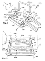
- a loading frame 112a of a load carrier 110a for a motor vehicle 111 is mounted on a supporting structure 113 schwenbkar.
- the support structure 113 is e.g. on sliding elements, not shown, e.g. Telescopic rods, slidably mounted on a body 115 of the motor vehicle 111.
- the support structure 113 is e.g. guided to guides not shown in the drawing, such as sliding guides, roller guides or the like.
- the loading rack 112a may e.g. in the manner of a drawer for disuse into a receiving space 116 of a body 115 of the motor vehicle 111 are inserted, for. hidden behind a bumper, so that the load carrier 110a in non-use position in front of an outer contour of the motor vehicle 111 is not or only slightly protruding.
- An alternative attachment concept provides that the support structure 113 has a receptacle 114 for a trailer coupling 180 of the motor vehicle 111.
- the support structure 113 and thus the load carrier 110a can be placed on the hitch 180 and removed when not in use from there and stowed at a storage location.
- the load carrier 110a N For transportation, e.g. after insertion into the receiving space 116 of the body 115, it is advantageous that the load carrier 110a N builds very compact in its non-use position. For space-saving accommodation of the load carrier 110a several of the measures described below in detail are provided.
- the load carrier 110a includes a pivoting subassembly 117a having pivoting members 118a-118d for expanding a loading area 119 are pivotally mounted on the skid 112a.
- the pivoting parts 118a-118d are pivotably mounted on a loading frame 120 of the loading frame 112a between a non-use position N and a use position G.
- the pivoting parts 118a-118d pivot about horizontal pivot axes 163 extending in the vehicle longitudinal direction 162.
- the pivoting parts 118a-118d project laterally in front of the loading frame 112a and thus increase the loading area 119.
- the pivoting parts 118a-118d project in the use position G in the transverse direction of the motor vehicle 111 in front of the loading frame 112a.
- the pivoting parts 118a-118d are pivoted inwardly into an inner area of the loading frame 120.
- plug-in components 122 of a plug-in component group 123 can be accommodated in the storage space 121 defined by the loading frame 112a when not in use.
- the pivoting parts 118a-118d and the plug-in components 122 are each space-saving stowed, so that the loading frame 112a can be inserted in the manner of a drawer in the receiving space 116 of the motor vehicle 111.
- the skid 112a is pivotally mounted with pivot joints 125.
- the pivot hinges 125 are provided at front ends of skid support members 126a, 126b which support support tubes 127 of the skid 112a. For example, a bolt 129 is pushed through the skid carrier parts 126a, 126b and the front ends 124 of the support structure 113.
- a pivot area 136 for example, for a tailgate of the motor vehicle 111 free.
- the skid support members 126a, 126b may be at least partially connected to each other, so that a U-shaped shape is formed.
- load carrier support members 126 ' which are U-shaped, the support tubes 127.
- the support tubes 127 are, for example, between upwardly in front of a bottom portion protruding legs 128 of the skid support members 126' added.
- the legs 128 are preferably designed somewhat narrower at their upper end, so that they rest laterally against the support tubes 127.
- the skid support members 126a, 126b are interconnected by means of connecting members 134 having a cross member 130 such that the support structure 113 is substantially U-shaped. Also, the pivotable skid 112a has a U-shape.
- the extending in the vehicle longitudinal direction 162 support tubes 127 are connected to each other by means of a transverse to the vehicle transverse direction of the cross member 131.
- the support tubes 127 and the cross member 131 which is preferably also configured as a tube, inserted into the connecting elements 135.
- the connecting elements 134, 135 are preferably plastic parts.
- the supporting structure 113 and the loading frame 112a are both U-shaped, their respective legs lying on one another in the driving position F, and the two transverse transverse sections, which are formed by the cross members 130, 131, being arranged on mutually opposite sides of the legs. so that at least in the driving position F a substantially rectangular frame arrangement is formed. This measure also contributes to the fact that the load carrier 110a is compact and yet has a high stability.
- the skid carrier parts 126a, 126b sit in a rider-like manner on carriers 154 of the carrier structure 113 extending in the vehicle longitudinal direction 162. Further, the support tubes rest on the supports 154, so that a stable construction is achieved for the driving operation of the motor vehicle 11.
- the outer contours 132 of the support tubes 127 are circular at least on the outside.
- the storage areas 139 of the loading frame 112 a are provided on the outer contours of the support tubes 127.
- the support tubes 127 form as it were bearing axles, the pivot part ends 140 of the pivot parts 118a-118d penetrate.
- the pivot dividers 140 are sleeve-like.
- pivoting parts 118a-118d are between pivoting stops 142a for the use position G and 143 for the non-use position N pivotable.
- the pivot stops 142a are provided by the skid support members 126a, the pivot stops 143 by the skid support members 126b.
- the pivot stops 142a, 143 are configured such that the pivot parts 118a-118d are pivotable at a pivot angle which is greater than 180 °.
- the wing-like pivot members 118a-118d are substantially horizontal when pivoted into the receiving space 116 in their non-use position N.
- the pivoting parts 118a-118d project obliquely downwards in front of the loading frame 112a.
- the pivot stops 142a are arranged such that this is possible for receiving, for example, large bicycles advantageous position of the pivot parts 118a-118d.
- the pivot stops 142a are provided by bottom portions of pivot recesses 144 on the skid support portions 126a.
- the pivot recesses 144 also have side stops 145 which limit axial displacement of the pivot members 118a-118d along their pivot axes 163.
- the pivot axes 163 extend in the vehicle longitudinal direction 162 and are defined by the support tubes 127. The axial fixing with respect to the pivot axes 163 facilitates the folding of the load carrier 110a into its non-use position N, because then the pivoting parts 118a-118d are arranged in alignment with one another in the storage space 121.
- the pivot parts 118a-118d are in the non-use position N on each other, wherein the respective lower pivot member 118a-118d abuts the respective pivot stop 143, while the other pivot member 118a-118d rests on the swivel stop 143 abutting pivot member 118a-118d. It does not matter which of the pivoting parts 118a-118d is the respective lower pivoting part, because, for example, deviating from the configuration according to FIG. 2 also the swing parts 118a and / or 118c may be the lower pivoting parts.
- the pivot stop 143 is configured as a longitudinal recess 146 which extends from a front, the respective support tube 127 holding and upwardly projecting end to the free end of the support tubes 127 back.
- the pivoting parts 118a-118d are grouped in pairs, wherein the pivoting parts 118a and 118c form a first pivoting part pair 148a and the pivoting parts 118b, 118d pivotally mounted on the opposite supporting tube 127 form a second pivoting part pair 149a.
- the pivoting parts 118a-118d are configured in the manner of wings, with the pivoting part ends 140 forming the respective bearing areas of the pivoting parts 118a-118d.
- the pivot parts 118a-118d are made of plastic and / or metal, preferably light metal, e.g. Aluminum or the like.
- the pivoting parts 118a-118d each have a groove 152 for receiving bicycles.
- Bicycles can also be fastened to clamps, belts or the like, not shown, by means of a vertical support bracket 153 which is in use.
- the clamps or belts can be detachably fastened, for example, to an upper transverse section of the retaining clip 153.
- Free ends of the U-shaped retaining bracket 153 are plugged into receptacles 156 of the skid 112 a.
- the plug-in receptacles 156 are provided, for example, on the connecting elements 134.
- the retaining bracket 153 is designed as a pivoting member, so that it is folded down, for example, in the non-use position N, wherein then lateral legs of the retaining bracket 153 next to the support tubes 127 run.
- the load securing devices 165a include retaining straps 166a with retaining strap members 168a, 169a secured to brackets 167 for looping around the load 150, for example for looping around a bicycle rim.
- the load attachment means 165a form encompassing means 170 for gripping the load 150.
- the brackets 167 project in front of the loading frame 112a in the direction of the pivoting parts 118a-118d swung out into the use position G.
- the brackets 167 are, for example, angle pieces, which are arranged on the skid support parts 126a in the region of the pivot stops 142a, preferably expediently below the pivot stops 142a.
- the holding straps 166a wrap around not only the load 150 but also the pivoting parts 118a-118d pivoted into the use position G.
- the load 150 can be clamped to the load carrier 110a with the load fastening devices 165a, so that the load fastening devices 165a form clamping devices 171a.
- toothing or latching projections 172 are present, in which a preferably biased by means of a spring in its holding position latching pawl 173 engages the other Garriementeil 169a.
- the latching projections 172 are inserted into a closing-like latching receptacle 174, where the latching latch 173, which is expediently spring-loaded in its catching position, engages in the latching projections 172 in a latching manner.
- the straps 166a can be stretched, so that at the same time the pivot parts 118a-118d are stretched in their respective position of use G.
- the luminaires are e.g. plug-in receptacles 160 inserted.
- the plug-in receptacles 160 are, for example, laterally open, in the drawing e.g. closed by plugs ends of the cross member 131. The lights then stand back laterally before the support tubes 127 before.
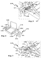
- FIG. 5 A second embodiment of a load carrier according to the invention with load securing devices according to the invention is shown in FIG FIG. 5 shown.
- holding straps 166b are fixed to pivot holder parts 176.
- the pivot holder parts 176 are pivotally mounted on the support structure 113.
- the pivot holder parts 176 have pivot recesses 177, which are penetrated by the support tubes 127.
- the Garriemener 168b, 169b are adjustable in length at the pivot holder parts 176.
- the pivot holder parts 176 have naturalschlingungsaus principleungen 178 through which the straps 166b are looped. Further, the Garriemenmaschine 168b, 169b are advantageously clamped against each other.
- the pivot holder parts 176 are suitably made of metal.
- the load attachment devices 165b are reinforced in the region of their mounting on the support structure 113.
- load carrier 110c whose basic structure corresponds to the load carrier 110a, pivot parts 118a '-118d' by coupling devices 181 connected to each other.
- the coupling devices 181 contain coupling elements 182 which respectively couple the pivoting parts 118a'-118d 'of the opposing pairs of pivoting parts 148b, 149b.
- a load rests on only two opposing pivot members 118a ', 118b' or 118c ', 118d' and is secured by a load attachment means, eg load attachment means 165a or 165b, both pairs of pivot members 148b, 149b and thus the entire pivot member assembly 117b are already there fixed pivotally.
- a load carrier 110d according to FIG. 7 has a loading frame 112d with U-shaped carrier profiles 190.
- the carrier profiles 190 sit in the driving position F (shown in the drawing) on the support structure 113.
- lateral legs 190 'of the U-beam profiles 190 surround the support structure 113.
- bearing receptacles 191 On the support profiles 190, which extend corresponding to the support tubes 127, bearing receptacles 191, for example, on upturned tabs 191 ', inserted tabs or the like, arranged on which pivoting parts 192d are pivotally mounted.
- Bolts 193 are pushed through bearing parts 194 and store them pivotally.
- the bearing parts 194 each hold a channel profile 195.
- the bolt 193 forms a pivot bearing shaft 196.
- the pivot parts 192 d are on a pivot stop 142 d of the support structure 113.
- Retaining straps 166d of load fasteners 165d with retainer piece members 168d, 169d are immediately penetrated by the pivot bearing shaft 196.
- the pivoting parts 118a provide a bearing region 197 for laying on the load 150, for example the bicycle 151, which has a distance 198 from the pivoting part bearing region 38, for example in FIG FIG. 5 shown.
- the load 150 is not placed directly on the storage area 38, but spaced therefrom on the respective pivoting parts.
- the load fastening devices 165a, 165b and 165d are each articulated on the bearing region 38 and engage the respective load 150, 151 on a holding region 199 remote from the support region 197.
- a force vector 200 is drawn in accordance with the force of the retaining belt 166a, 166b, 166d.
- the belt force 200 has a vehicle transverse direction, i. to the vehicle center extending force component, as well as a vertical, running in the Z direction component of force.
- a load carrier 110e essentially corresponds to the load carrier 110d.
- Swivel parts 192e are in one piece, in contrast to the swiveling parts 192d, that is to say they have integrated bearing ends, which are pivotally mounted on the bolts 193. Also pivotally mounted on the bolt 193 retaining strap 166e of load attachment 165e. On both sides of the pivoting parts 192, a respective retaining part 168e, 169e is pivotally mounted on the bolt 193.
- a clamping receptacle for locking and tensioning of the other Garriementeils 168e is provided on retaining part 169e.
- the free end of the retaining member 168e is wrapped around the wheel to be held (not shown) and inserted into the clamping receptacle 201.
- a locking or latching pawl 202 is pivotally mounted on a bearing part 203.
- the bearing part 203 is U-shaped and has approximately the width of the retaining part 168e, so that it can be inserted into the clamping receptacle 201 between two side legs, on which the latching pawl 202 is pivotally mounted. There engages the latch 202 with a formed by locking teeth counter teeth 204 on Garriementeil 168e.
- the latch 202 is spring-loaded in the direction of its detent position, so that it automatically locks with the counter teeth 204.
- the clamping device 171e namely has a tensioning lever 205, which is also pivotally mounted on the bearing part 203.
- the latching pawl 202 and the tensioning lever 205 are arranged one behind the other in the direction of passage of the retaining part 168e. While the detent pawl 202 provides a firm, latched hold of the retaining part 168e on the retaining part 169e, the retaining part 168e can be additionally tensioned against the retaining part 169e by means of the tensioning lever 205.
- a clamping projection 207 is arranged, which engages in the counter toothing 204.
- the clamping projection 207 engages in the counter teeth 204 and promotes the retaining member 168e in the clamping direction, that is to the latch 202 out. This slips away during the clamping movement or conveying movement of the clamping lever 204 via the counter teeth 204 and engages at the end of the clamping movement in a matching recess of the counter teeth 204, so that the Halteriementeil 168e is stretched closer to the load to be fastened.
- the clamping projection 207 slips over the counter teeth 204, so that a total of a ratchet movement is formed.
- the operator can easily grasp the tension lever 205 at the lever arm 210 thereof, so that a relatively large clamping force is available.
Landscapes
- Engineering & Computer Science (AREA)
- Mechanical Engineering (AREA)
- Fittings On The Vehicle Exterior For Carrying Loads, And Devices For Holding Or Mounting Articles (AREA)
- Arrangement Or Mounting Of Propulsion Units For Vehicles (AREA)
Claims (23)
- Support de charge pour un véhicule automobile (111), en particulier une voiture de tourisme, avec un bâti de chargement (112a ; 112d) qui est prévu pour porter une charge (150), qui dépasse, dans une position de travail du support de charge (110a-110e), vers l'arrière d'une zone arrière du véhicule automobile (111) et qui met à disposition une zone de chargement (119) pour le chargement d'une charge (150), avec un ensemble de partie pivotante (117a; 117b) présentant au moins une partie pivotante (118a-118d ; 192d; 192e; 118a'-d') pour l'élargissement de la zone de chargement (119), l'au moins une partie pivotante (118a-118d ; 192d ; 192e ; 118a'-d') étant logée de manière pivotante avec une zone de palier de partie pivotante (38) sur une zone de palier de bâti de chargement (139) du bâti de chargement (112a; 112d) autour d'un axe de pivotement (63) entre une position d'utilisation (G) et une position de non utilisation (N), sur la zone de palier de bâti de chargement (139) étant disposée une butée de pivotement (142a; 142d), contre laquelle l'au moins une partie pivotante (118a-118d ; 192d ; 192e ; 118a'-d') bute dans la position d'utilisation (G), et sur le bâti de chargement (112a ; 112d) sur la zone de palier de bâti de chargement (139) étant fixé au moins un dispositif de fixation de charge (165a ; 165b ; 165d) pour la fixation d'une charge (150) disposée sur l'au moins une partie pivotante (118a-118d ; 192d ; 192e ; 118a'-d'), l'au moins un dispositif de fixation de charge (165a ; 165b ; 165d) fixant de manière solidaire en pivotement par le maintien de la charge (150) fixée avec lui l'au moins une partie pivotante (118a-118d; 192d ; 192e ; 118a'-d'), caractérisé en ce que l'au moins un dispositif de fixation de charge (165a ; 165b ; 165d) est fixé sur des côtés opposés de l'au moins une partie pivotante (118a-118d ; 192d ; 192e ; 118a'-d') sur le bâti de chargement (112a ; 112d).
- Support de charge selon la revendication 1, caractérisé en ce que le dispositif de fixation de charge (165a ; 165b ; 165d) contient ou forme un dispositif de serrage (171 a-171 e) pour le serrage de la charge (150) sur le bâti de chargement (112a ; 112d).
- Support de charge selon la revendication 1 ou 2, caractérisé en ce que l'au moins un dispositif de fixation de charge (165a ; 165b ; 165d) est fixé dans une zone de pivotement de l'au moins une partie pivotante (118a-118d ; 192d ; 192e ; 118a'-d') près de la butée de pivotement (142a ; 142d) et/ou en dehors d'une zone de pivotement de l'au moins une partie pivotante (118a-118d ; 192d ; 192e ; 118a'-d') sur le bâti de chargement (112a ; 112d).
- Support de charge selon l'une quelconque des revendications précédentes, caractérisé en ce que l'au moins une partie pivotante (118a-118d ; 192d ; 192e ; 118a'-d') présente une zone d'appui (197) pour l'appui de la charge (150), en particulier une zone de placement pour un vélo (151), une distance (198) par rapport à la zone de palier de partie pivotante (38) et en ce que l'au moins un dispositif de fixation de charge (165a ; 165b ; 165d) saisit la charge (150) sur une zone de retenue (199) éloignée de la zone d'appui (197).
- Support de charge selon l'une quelconque des revendications précédentes, caractérisé en ce que l'au moins un dispositif de fixation (165a ; 165b ; 165d) présente un dispositif d'enveloppement (170) pour envelopper la charge (150), en particulier une jante d'un vélo (151), le dispositif d'enveloppement (170) enveloppant de préférence l'au moins une partie pivotante (118a-118d ; 192d ; 192e ; 118a'-d') si l'au moins une partie pivotante (118a-118d ; 192d ; 192e ; 118a'-d') est dans sa position d'utilisation.
- Support de charge selon la revendication 5, caractérisé en ce que le dispositif d'enveloppement (170) entoure la charge (150) sur une zone de retenue (199) qui est éloignée d'une zone d'appui (197) pour l'appui de la charge (150).
- Support de charge selon l'une quelconque des revendications 5 ou 6, caractérisé en ce que le dispositif d'enveloppement (170) comporte un étrier d'enveloppement ou un crochet d'enveloppement pour recourber la charge ou une courroie de retenue (166a ; 166b ; 166d ; 166e), en particulier une courroie de serrage pour enlacer la charge (150), la courroie de retenue (166a ; 166b ; 166d ; 166e) comportant en particulier au moins deux parties de courroie de retenue (168a-e, 169a-e).
- Support de charge selon la revendication 7, caractérisé en ce qu'il présente un logement d'encliquetage (174) pour l'encliquetage avec des saillies d'encliquetage (172) sur une courroie de retenue (166a ; 166b ; 166d ; 166e) ou une partie de courroie de retenue (168a-168e).
- Support de charge selon la revendication 7 ou 8, caractérisé en ce qu'il comporte un levier de serrage (205) pour le serrage de la courroie de retenue (166a ; 166b ; 166d ; 166e), en particulier des parties de courroie de retenue (168a-e, 169a-e) l'une contre l'autre, le levier de serrage (205) présentant en particulier une zone dentée pour l'engagement dans une contre-denture (204) sur une courroie de retenue (166a-166b ; 166d ; 166e).
- Support de charge selon la revendication 9, caractérisé en ce que le levier de serrage (205) est configuré au sens d'un entraînement à cliquet, le levier de serrage (205) étant en engagement dans le sens de serrage avec la courroie de retenue (166a ; 166b ; 166d ; 166e) à serrer, alors qu'il pivote librement ou par encliquetage dans le sens opposé au sens de serrage par le biais de la courroie de retenue (166a ; 166b ; 166d ; 166e).
- Support de charge selon la revendication 9 ou 10, caractérisé en ce qu'un cliquet de verrouillage (202) est associé au levier de serrage (205) pour la retenue de la courroie de retenue (166a ; 166b ; 166d ; 166e) transportée par le levier de serrage (205) lors d'une course de serrage dans le sens du cliquet de verrouillage (202).
- Support de charge selon l'une quelconque des revendications 7 à 11, caractérisé en ce que la courroie de retenue (166a ; 166b ; 166d ; 166e) est fixée sur au moins une extrémité sur une partie du support de pivotement (176) logée de manière pivotante sur la zone de palier de bâti de chargement (139) et/ou en ce que la courroie de retenue (166a; 166b ; 166d ; 166e) est traversée par un arbre de palier de pivotement (196).
- Support de charge selon l'une quelconque des revendications 7 à 12, caractérisé en ce que la courroie de retenue (166a ; 166b ; 166d ; 166e) présente dans son sens longitudinal des sections avec une rigidité différente, en particulier des sections se composant de composants synthétiques avec une rigidité différente.
- Support de charge selon l'une quelconque des revendications précédentes, caractérisé en ce que l'au moins une partie pivotante (118a-118d ; 192d ; 192e ; 118a'-d') présente au moins une rigole (52), en particulier pour le logement d'un vélo (151).
- Support de charge selon l'une quelconque des revendications précédentes, caractérisé en ce que l'au moins une partie pivotante (118a-118d ; 192d ; 192e ; 118a'-d') est fixée axialement sensiblement de manière immobile par rapport à son axe de pivotement (163).
- Support de charge selon l'une quelconque des revendications précédentes, caractérisé en ce que l'ensemble de partie pivotante (117a ; 117b) présente au moins deux parties pivotantes (118a ; 118d ; 192d ; 192e ; 118a'-d') qui sont logées de manière pivotante sur deux zones de palier de bâti de chargement (139) opposées, et en ce que les au moins deux parties pivotantes (118a-118d ; 192d ; 192e ; 118a'-d') sont disposées dans la position de non utilisation (N) l'une sur l'autre ou l'une à côté de l'autre dans un espace de dépôt (121) délimité par le bâti de chargement (112a ; 112d) et dépassent du bâti de chargement (112a ; 112d) dans la position d'utilisation (G) en s'alignant l'une avec l'autre, en particulier en ce que les parties pivotantes (118a ; 118d ; 192d ; 192e ; 118a'-d') opposées dépassent, dans la position d'utilisation (G), en biais vers le bas du bâti de chargement (112a ; 112d).
- Support de charge selon l'une quelconque des revendications précédentes, caractérisé en ce que l'ensemble de partie pivotante (117a ; 117b) présente une première et au moins une seconde paire (148a ; 149a ; 148b ; 149b) de parties pivotantes (118a; 118d; 192d ; 192e ; 118a'-d') logées de manière opposée sur le bâti de chargement (112a; 112d), les parties pivotantes (118a-118d) au moins de l'une des paires de parties pivotantes (148a, 149a ; 148b, 149b) étant pivotantes individuellement ou couplées par un dispositif de couplage (181).
- Support de charge selon l'une quelconque des revendications précédentes, caractérisé en ce que l'au moins une partie pivotante (118a ; 118d ; 192d ; 192e ; 118a'-d') est configurée comme une aile pivotante et en ce que la partie pivotante (118a; 118d ; 192d ; 192e ; 118a'-d') présente une seule rigole (52, 161).
- Support de charge selon l'une quelconque des revendications précédentes, caractérisé en ce que la zone de palier de bâti de chargement (139) est prévue sur un tube (127) du bâti de chargement qui est enveloppé par l'au moins une partie pivotante (118a ; 118d ; 192d ; 192e ; 118a'-d') ou qui est enfiché par un logement de palier de pivotement (141) de l'au moins une partie pivotante (118a ; 118d ; 192d ; 192e ; 118a'-d'), la butée de pivotement (142a ; 142d) étant de préférence disposée sur une partie de support de bâti de chargement (126, 126b, 126') en particulier en forme de U, maintenant le tube (127).
- Support de charge selon l'une quelconque des revendications précédentes, caractérisé en ce qu'il présente au moins un logement à enficher (156) pour au moins un composant à enficher (122) qui est enfiché pour une position d'utilisation (G) dans l'au moins un logement à enficher (156), l'au moins un composant à enficher (122) comportant en particulier un appui qui dépasse dans la position d'utilisation (G) vers le haut du bâti de chargement (112a ; 112d) et/ou comporte en particulier une lampe qui est disposée dans la position d'utilisation (G) sur le bâti de chargement (112a ; 112d) ou une partie pivotante (118a-118d ; 192d ; 192e ; 118a'-d').
- Support de charge selon la revendication 20, caractérisé en ce que l'au moins un composant à enficher (122) forme un constituant d'un groupe de composant à enficher (123) qui peut être disposé dans la position de non utilisation (N) dans un espace de dépôt (121) du bâti de chargement (112a ; 112d).
- Support de charge selon l'une quelconque des revendications précédentes, caractérisé en ce qu'il présente un support pour la disposition détachable sur un attelage (180) du véhicule automobile (111) et/ou en ce que le bâti de chargement (112a ; 112d) est logé de manière pivotante et/ou mobile sur le véhicule automobile (111) entre une position d'utilisation (G) dépassant vers l'arrière du véhicule automobile (111) et une position de non utilisation (N) cachée derrière ou sous un contour de carrosserie du véhicule automobile (111).
- Support de charge selon l'une quelconque des revendications précédentes, caractérisé en ce que le bâti de chargement (112a ; 112d) est logé de manière pivotante et/ou mobile sur une structure portante (113) entre une position de roulement (F) prévue pour un mode de roulement du véhicule automobile (111) et une position de chargement (L) prévue pour le chargement et le déchargement du véhicule automobile (111) et en ce que le bâti de chargement (112a ; 112d) libère dans la position de chargement (L) une zone pivotante (36) d'un hayon du véhicule automobile (111).
Priority Applications (1)
| Application Number | Priority Date | Filing Date | Title |
|---|---|---|---|
| EP13005196.4A EP2730464B1 (fr) | 2007-07-11 | 2008-06-28 | Support de charge pour un véhicule automobile |
Applications Claiming Priority (2)
| Application Number | Priority Date | Filing Date | Title |
|---|---|---|---|
| DE102007033015 | 2007-07-11 | ||
| DE102008006814A DE102008006814A1 (de) | 2007-07-11 | 2008-01-31 | Lastenträger für ein Kraftfahrzeug |
Related Child Applications (2)
| Application Number | Title | Priority Date | Filing Date |
|---|---|---|---|
| EP13005196.4A Division EP2730464B1 (fr) | 2007-07-11 | 2008-06-28 | Support de charge pour un véhicule automobile |
| EP13005196.4 Division-Into | 2013-11-04 |
Publications (3)
| Publication Number | Publication Date |
|---|---|
| EP2014510A2 EP2014510A2 (fr) | 2009-01-14 |
| EP2014510A3 EP2014510A3 (fr) | 2011-01-05 |
| EP2014510B1 true EP2014510B1 (fr) | 2013-12-18 |
Family
ID=39892370
Family Applications (1)
| Application Number | Title | Priority Date | Filing Date |
|---|---|---|---|
| EP08011750.0A Active EP2014510B1 (fr) | 2007-07-11 | 2008-06-28 | Support de charge pour un véhicule automobile |
Country Status (1)
| Country | Link |
|---|---|
| EP (1) | EP2014510B1 (fr) |
Cited By (1)
| Publication number | Priority date | Publication date | Assignee | Title |
|---|---|---|---|---|
| DE102016103595A1 (de) | 2016-02-24 | 2017-08-24 | Westfalia-Automotive Gmbh | Befestigungsvorrichtung für einen Lastenträger |
Families Citing this family (4)
| Publication number | Priority date | Publication date | Assignee | Title |
|---|---|---|---|---|
| DE102009016534B4 (de) | 2009-04-06 | 2011-06-16 | Uebler Gmbh | Lastenträger für ein Kraftfahrzeug |
| DE102011122285A1 (de) * | 2011-12-23 | 2013-06-27 | Westfalia-Automotive Gmbh | Lastenträger mit an einem Grundträger beweglich gelagerten Lasttragteilen |
| EP2703224B1 (fr) | 2012-08-28 | 2015-04-29 | Thule Sweden AB | Support de charge pour véhicule |
| ES2791357T3 (es) * | 2017-07-10 | 2020-11-04 | Aurilis Group Italia S R L | Dispositivo para transportar una carga en vehículos de motor equipados con soportes de carga ajustables |
Family Cites Families (8)
| Publication number | Priority date | Publication date | Assignee | Title |
|---|---|---|---|---|
| US4875608A (en) * | 1988-06-21 | 1989-10-24 | Graber Products, Inc. | Vehicle mounted foldable bicycle carrier |
| US5579973A (en) * | 1995-05-12 | 1996-12-03 | Taft; William O. | Carrier for lightweight two wheel vehicles, with capability for also towing a trailer |
| US6431423B1 (en) * | 1999-11-23 | 2002-08-13 | Yakima Products, Inc. | Assembly for carrying a bicycle on a vehicle |
| US20050116002A1 (en) * | 2002-07-08 | 2005-06-02 | Thule Sweden Ab | Load carrier |
| DE10309327A1 (de) * | 2003-03-04 | 2004-10-07 | Bayerische Motoren Werke Ag | Gepäckträger an einem Kraftfahrzeug |
| FR2866851B1 (fr) * | 2004-02-26 | 2007-05-25 | Renault Sas | Porte-velo(s) comportant une partie apte a etre repliee transversalement |
| DE102005054059B3 (de) * | 2005-11-10 | 2007-06-21 | Magna Car Top Systems Gmbh | Lastenträger für Kraftfahrzeuge |
| DE102007023495A1 (de) | 2007-05-19 | 2008-11-20 | Uebler Gmbh | Lastenträger für ein Kraftfahrzeug |
-
2008
- 2008-06-28 EP EP08011750.0A patent/EP2014510B1/fr active Active
Cited By (4)
| Publication number | Priority date | Publication date | Assignee | Title |
|---|---|---|---|---|
| DE102016103595A1 (de) | 2016-02-24 | 2017-08-24 | Westfalia-Automotive Gmbh | Befestigungsvorrichtung für einen Lastenträger |
| WO2017144280A1 (fr) | 2016-02-24 | 2017-08-31 | Westfalia-Automotive Gmbh | Dispositif de fixation pour porte-charge |
| AU2017224026B2 (en) * | 2016-02-24 | 2021-09-09 | Westfalia-Automotive Gmbh | Fastening device for a load carrier |
| US11203303B2 (en) | 2016-02-24 | 2021-12-21 | Westfalia-Automotive Gmbh | Fastening device for a load carrier |
Also Published As
| Publication number | Publication date |
|---|---|
| EP2014510A2 (fr) | 2009-01-14 |
| EP2014510A3 (fr) | 2011-01-05 |
Similar Documents
| Publication | Publication Date | Title |
|---|---|---|
| EP2730464B1 (fr) | Support de charge pour un véhicule automobile | |
| DE60013385T2 (de) | Fahrradträger angepasst zur Montage im Inneren eines Kraftfahrzeuges | |
| DE10144550C2 (de) | Lastenträger für ein Fahrzeugheck | |
| DE202014102630U1 (de) | Hilfsgestell für ein Fahrzeug | |
| EP2098412B1 (fr) | Support de charge | |
| DE102017123890A1 (de) | Trageinrichtung | |
| EP2014510B1 (fr) | Support de charge pour un véhicule automobile | |
| DE202012103182U1 (de) | Lastenträger | |
| DE102004033809B4 (de) | Aufnahmevorrichtung für ein Fahrzeug | |
| DE10309327A1 (de) | Gepäckträger an einem Kraftfahrzeug | |
| DE29607956U1 (de) | Gepäckträger für ein Kraftfahrzeug mit einem Kofferraum, vorzugsweise für ein Personenkraftfahrzeug | |
| EP0939005A1 (fr) | Dispositif pour fixer des articles dans le compartiment à bagages d'un véhicule | |
| DE102010045356A1 (de) | Lastenträger mit einem Schwenkschiebelager | |
| DE4241142A1 (de) | Lastenträger für ein Fahrzeug | |
| DE19942530B4 (de) | Tisch für ein Fahrzeug | |
| DE102010012333A1 (de) | Heckträger | |
| DE102011121400A1 (de) | Gepäckhalter für Fahrzeuge sowie Kraftfahrzeug | |
| DE102010012774A1 (de) | Modulares Hecktragesystem | |
| DE202009011325U1 (de) | Transportvorrichtung | |
| DE19537287C2 (de) | Container-Transport-Vorrichtung für ein Fahrzeug | |
| DE102010035194A1 (de) | Vorrichtung zum Sichern von Ladung eines Fahrzeuges | |
| DE602005000912T2 (de) | Hecktragvorrichtung für Fahrzeuge | |
| DE202010012600U1 (de) | Klemmhalter und damit ausgestatteter Lastenträger | |
| DE19615030C1 (de) | Halterung für den Innenraum eines Fahrzeuges mit umklappbarer Rückbank | |
| DE102004057647B4 (de) | Tragevorrichtung für Gegenstände an der Außenseite eines Kraftfahrzeugs |
Legal Events
| Date | Code | Title | Description |
|---|---|---|---|
| PUAI | Public reference made under article 153(3) epc to a published international application that has entered the european phase |
Free format text: ORIGINAL CODE: 0009012 |
|
| AK | Designated contracting states |
Kind code of ref document: A2 Designated state(s): AT BE BG CH CY CZ DE DK EE ES FI FR GB GR HR HU IE IS IT LI LT LU LV MC MT NL NO PL PT RO SE SI SK TR |
|
| AX | Request for extension of the european patent |
Extension state: AL BA MK RS |
|
| PUAL | Search report despatched |
Free format text: ORIGINAL CODE: 0009013 |
|
| AK | Designated contracting states |
Kind code of ref document: A3 Designated state(s): AT BE BG CH CY CZ DE DK EE ES FI FR GB GR HR HU IE IS IT LI LT LU LV MC MT NL NO PL PT RO SE SI SK TR |
|
| AX | Request for extension of the european patent |
Extension state: AL BA MK RS |
|
| 17P | Request for examination filed |
Effective date: 20110604 |
|
| RIC1 | Information provided on ipc code assigned before grant |
Ipc: B60R 9/06 20060101AFI20110719BHEP Ipc: B60R 9/10 20060101ALI20110719BHEP |
|
| AKX | Designation fees paid |
Designated state(s): AT BE BG CH CY CZ DE DK EE ES FI FR GB GR HR HU IE IS IT LI LT LU LV MC MT NL NO PL PT RO SE SI SK TR |
|
| GRAP | Despatch of communication of intention to grant a patent |
Free format text: ORIGINAL CODE: EPIDOSNIGR1 |
|
| INTG | Intention to grant announced |
Effective date: 20130628 |
|
| GRAS | Grant fee paid |
Free format text: ORIGINAL CODE: EPIDOSNIGR3 |
|
| GRAA | (expected) grant |
Free format text: ORIGINAL CODE: 0009210 |
|
| AK | Designated contracting states |
Kind code of ref document: B1 Designated state(s): AT BE BG CH CY CZ DE DK EE ES FI FR GB GR HR HU IE IS IT LI LT LU LV MC MT NL NO PL PT RO SE SI SK TR |
|
| REG | Reference to a national code |
Ref country code: GB Ref legal event code: FG4D Free format text: NOT ENGLISH |
|
| REG | Reference to a national code |
Ref country code: CH Ref legal event code: EP |
|
| REG | Reference to a national code |
Ref country code: AT Ref legal event code: REF Ref document number: 645468 Country of ref document: AT Kind code of ref document: T Effective date: 20140115 |
|
| REG | Reference to a national code |
Ref country code: IE Ref legal event code: FG4D Free format text: LANGUAGE OF EP DOCUMENT: GERMAN |
|
| REG | Reference to a national code |
Ref country code: DE Ref legal event code: R096 Ref document number: 502008011079 Country of ref document: DE Effective date: 20140213 |
|
| REG | Reference to a national code |
Ref country code: NL Ref legal event code: VDEP Effective date: 20131218 |
|
| PG25 | Lapsed in a contracting state [announced via postgrant information from national office to epo] |
Ref country code: HR Free format text: LAPSE BECAUSE OF FAILURE TO SUBMIT A TRANSLATION OF THE DESCRIPTION OR TO PAY THE FEE WITHIN THE PRESCRIBED TIME-LIMIT Effective date: 20131218 Ref country code: FI Free format text: LAPSE BECAUSE OF FAILURE TO SUBMIT A TRANSLATION OF THE DESCRIPTION OR TO PAY THE FEE WITHIN THE PRESCRIBED TIME-LIMIT Effective date: 20131218 Ref country code: LT Free format text: LAPSE BECAUSE OF FAILURE TO SUBMIT A TRANSLATION OF THE DESCRIPTION OR TO PAY THE FEE WITHIN THE PRESCRIBED TIME-LIMIT Effective date: 20131218 Ref country code: NO Free format text: LAPSE BECAUSE OF FAILURE TO SUBMIT A TRANSLATION OF THE DESCRIPTION OR TO PAY THE FEE WITHIN THE PRESCRIBED TIME-LIMIT Effective date: 20140318 Ref country code: SE Free format text: LAPSE BECAUSE OF FAILURE TO SUBMIT A TRANSLATION OF THE DESCRIPTION OR TO PAY THE FEE WITHIN THE PRESCRIBED TIME-LIMIT Effective date: 20131218 |
|
| REG | Reference to a national code |
Ref country code: LT Ref legal event code: MG4D |
|
| PG25 | Lapsed in a contracting state [announced via postgrant information from national office to epo] |
Ref country code: LV Free format text: LAPSE BECAUSE OF FAILURE TO SUBMIT A TRANSLATION OF THE DESCRIPTION OR TO PAY THE FEE WITHIN THE PRESCRIBED TIME-LIMIT Effective date: 20131218 |
|
| PG25 | Lapsed in a contracting state [announced via postgrant information from national office to epo] |
Ref country code: EE Free format text: LAPSE BECAUSE OF FAILURE TO SUBMIT A TRANSLATION OF THE DESCRIPTION OR TO PAY THE FEE WITHIN THE PRESCRIBED TIME-LIMIT Effective date: 20131218 Ref country code: IS Free format text: LAPSE BECAUSE OF FAILURE TO SUBMIT A TRANSLATION OF THE DESCRIPTION OR TO PAY THE FEE WITHIN THE PRESCRIBED TIME-LIMIT Effective date: 20140418 |
|
| PG25 | Lapsed in a contracting state [announced via postgrant information from national office to epo] |
Ref country code: CY Free format text: LAPSE BECAUSE OF FAILURE TO SUBMIT A TRANSLATION OF THE DESCRIPTION OR TO PAY THE FEE WITHIN THE PRESCRIBED TIME-LIMIT Effective date: 20131218 Ref country code: NL Free format text: LAPSE BECAUSE OF FAILURE TO SUBMIT A TRANSLATION OF THE DESCRIPTION OR TO PAY THE FEE WITHIN THE PRESCRIBED TIME-LIMIT Effective date: 20131218 Ref country code: PT Free format text: LAPSE BECAUSE OF FAILURE TO SUBMIT A TRANSLATION OF THE DESCRIPTION OR TO PAY THE FEE WITHIN THE PRESCRIBED TIME-LIMIT Effective date: 20140418 Ref country code: PL Free format text: LAPSE BECAUSE OF FAILURE TO SUBMIT A TRANSLATION OF THE DESCRIPTION OR TO PAY THE FEE WITHIN THE PRESCRIBED TIME-LIMIT Effective date: 20131218 Ref country code: SK Free format text: LAPSE BECAUSE OF FAILURE TO SUBMIT A TRANSLATION OF THE DESCRIPTION OR TO PAY THE FEE WITHIN THE PRESCRIBED TIME-LIMIT Effective date: 20131218 Ref country code: RO Free format text: LAPSE BECAUSE OF FAILURE TO SUBMIT A TRANSLATION OF THE DESCRIPTION OR TO PAY THE FEE WITHIN THE PRESCRIBED TIME-LIMIT Effective date: 20131218 Ref country code: ES Free format text: LAPSE BECAUSE OF FAILURE TO SUBMIT A TRANSLATION OF THE DESCRIPTION OR TO PAY THE FEE WITHIN THE PRESCRIBED TIME-LIMIT Effective date: 20131218 Ref country code: CZ Free format text: LAPSE BECAUSE OF FAILURE TO SUBMIT A TRANSLATION OF THE DESCRIPTION OR TO PAY THE FEE WITHIN THE PRESCRIBED TIME-LIMIT Effective date: 20131218 |
|
| REG | Reference to a national code |
Ref country code: DE Ref legal event code: R097 Ref document number: 502008011079 Country of ref document: DE |
|
| REG | Reference to a national code |
Ref country code: DE Ref legal event code: R082 Ref document number: 502008011079 Country of ref document: DE Representative=s name: BREGENZER, MICHAEL, DIPL.-ING., DE Ref country code: DE Ref legal event code: R082 Ref document number: 502008011079 Country of ref document: DE Representative=s name: PATENTANWAELTE BREGENZER UND REULE PARTNERSCHA, DE |
|
| PLBE | No opposition filed within time limit |
Free format text: ORIGINAL CODE: 0009261 |
|
| STAA | Information on the status of an ep patent application or granted ep patent |
Free format text: STATUS: NO OPPOSITION FILED WITHIN TIME LIMIT |
|
| PG25 | Lapsed in a contracting state [announced via postgrant information from national office to epo] |
Ref country code: DK Free format text: LAPSE BECAUSE OF FAILURE TO SUBMIT A TRANSLATION OF THE DESCRIPTION OR TO PAY THE FEE WITHIN THE PRESCRIBED TIME-LIMIT Effective date: 20131218 |
|
| 26N | No opposition filed |
Effective date: 20140919 |
|
| REG | Reference to a national code |
Ref country code: DE Ref legal event code: R082 Ref document number: 502008011079 Country of ref document: DE Representative=s name: PATENTANWAELTE BREGENZER UND REULE PARTNERSCHA, DE |
|
| REG | Reference to a national code |
Ref country code: DE Ref legal event code: R097 Ref document number: 502008011079 Country of ref document: DE Effective date: 20140919 |
|
| PG25 | Lapsed in a contracting state [announced via postgrant information from national office to epo] |
Ref country code: LU Free format text: LAPSE BECAUSE OF FAILURE TO SUBMIT A TRANSLATION OF THE DESCRIPTION OR TO PAY THE FEE WITHIN THE PRESCRIBED TIME-LIMIT Effective date: 20140628 Ref country code: MC Free format text: LAPSE BECAUSE OF FAILURE TO SUBMIT A TRANSLATION OF THE DESCRIPTION OR TO PAY THE FEE WITHIN THE PRESCRIBED TIME-LIMIT Effective date: 20131218 |
|
| REG | Reference to a national code |
Ref country code: CH Ref legal event code: PL |
|
| GBPC | Gb: european patent ceased through non-payment of renewal fee |
Effective date: 20140628 |
|
| REG | Reference to a national code |
Ref country code: IE Ref legal event code: MM4A |
|
| PG25 | Lapsed in a contracting state [announced via postgrant information from national office to epo] |
Ref country code: CH Free format text: LAPSE BECAUSE OF NON-PAYMENT OF DUE FEES Effective date: 20140630 Ref country code: IE Free format text: LAPSE BECAUSE OF NON-PAYMENT OF DUE FEES Effective date: 20140628 Ref country code: LI Free format text: LAPSE BECAUSE OF NON-PAYMENT OF DUE FEES Effective date: 20140630 |
|
| PG25 | Lapsed in a contracting state [announced via postgrant information from national office to epo] |
Ref country code: GB Free format text: LAPSE BECAUSE OF NON-PAYMENT OF DUE FEES Effective date: 20140628 Ref country code: SI Free format text: LAPSE BECAUSE OF FAILURE TO SUBMIT A TRANSLATION OF THE DESCRIPTION OR TO PAY THE FEE WITHIN THE PRESCRIBED TIME-LIMIT Effective date: 20131218 |
|
| REG | Reference to a national code |
Ref country code: AT Ref legal event code: MM01 Ref document number: 645468 Country of ref document: AT Kind code of ref document: T Effective date: 20140628 |
|
| PG25 | Lapsed in a contracting state [announced via postgrant information from national office to epo] |
Ref country code: AT Free format text: LAPSE BECAUSE OF NON-PAYMENT OF DUE FEES Effective date: 20140628 |
|
| PG25 | Lapsed in a contracting state [announced via postgrant information from national office to epo] |
Ref country code: MT Free format text: LAPSE BECAUSE OF FAILURE TO SUBMIT A TRANSLATION OF THE DESCRIPTION OR TO PAY THE FEE WITHIN THE PRESCRIBED TIME-LIMIT Effective date: 20131218 |
|
| REG | Reference to a national code |
Ref country code: FR Ref legal event code: PLFP Year of fee payment: 9 |
|
| PG25 | Lapsed in a contracting state [announced via postgrant information from national office to epo] |
Ref country code: BG Free format text: LAPSE BECAUSE OF FAILURE TO SUBMIT A TRANSLATION OF THE DESCRIPTION OR TO PAY THE FEE WITHIN THE PRESCRIBED TIME-LIMIT Effective date: 20131218 |
|
| PG25 | Lapsed in a contracting state [announced via postgrant information from national office to epo] |
Ref country code: GR Free format text: LAPSE BECAUSE OF FAILURE TO SUBMIT A TRANSLATION OF THE DESCRIPTION OR TO PAY THE FEE WITHIN THE PRESCRIBED TIME-LIMIT Effective date: 20140319 Ref country code: IT Free format text: LAPSE BECAUSE OF FAILURE TO SUBMIT A TRANSLATION OF THE DESCRIPTION OR TO PAY THE FEE WITHIN THE PRESCRIBED TIME-LIMIT Effective date: 20131218 |
|
| PG25 | Lapsed in a contracting state [announced via postgrant information from national office to epo] |
Ref country code: TR Free format text: LAPSE BECAUSE OF FAILURE TO SUBMIT A TRANSLATION OF THE DESCRIPTION OR TO PAY THE FEE WITHIN THE PRESCRIBED TIME-LIMIT Effective date: 20131218 Ref country code: BE Free format text: LAPSE BECAUSE OF FAILURE TO SUBMIT A TRANSLATION OF THE DESCRIPTION OR TO PAY THE FEE WITHIN THE PRESCRIBED TIME-LIMIT Effective date: 20140630 Ref country code: HU Free format text: LAPSE BECAUSE OF FAILURE TO SUBMIT A TRANSLATION OF THE DESCRIPTION OR TO PAY THE FEE WITHIN THE PRESCRIBED TIME-LIMIT; INVALID AB INITIO Effective date: 20080628 |
|
| REG | Reference to a national code |
Ref country code: FR Ref legal event code: PLFP Year of fee payment: 10 |
|
| REG | Reference to a national code |
Ref country code: FR Ref legal event code: PLFP Year of fee payment: 11 |
|
| PGFP | Annual fee paid to national office [announced via postgrant information from national office to epo] |
Ref country code: FR Payment date: 20220510 Year of fee payment: 15 |
|
| PG25 | Lapsed in a contracting state [announced via postgrant information from national office to epo] |
Ref country code: FR Free format text: LAPSE BECAUSE OF NON-PAYMENT OF DUE FEES Effective date: 20230630 |
|
| PGFP | Annual fee paid to national office [announced via postgrant information from national office to epo] |
Ref country code: DE Payment date: 20250627 Year of fee payment: 18 |