EP2014966A2 - A bellows like collapsible clip - Google Patents
A bellows like collapsible clip Download PDFInfo
- Publication number
- EP2014966A2 EP2014966A2 EP08157882A EP08157882A EP2014966A2 EP 2014966 A2 EP2014966 A2 EP 2014966A2 EP 08157882 A EP08157882 A EP 08157882A EP 08157882 A EP08157882 A EP 08157882A EP 2014966 A2 EP2014966 A2 EP 2014966A2
- Authority
- EP
- European Patent Office
- Prior art keywords
- clip
- configuration
- sleeve
- actuator
- force
- Prior art date
- Legal status (The legal status is an assumption and is not a legal conclusion. Google has not performed a legal analysis and makes no representation as to the accuracy of the status listed.)
- Granted
Links
Images


Classifications
-
- F—MECHANICAL ENGINEERING; LIGHTING; HEATING; WEAPONS; BLASTING
- F16—ENGINEERING ELEMENTS AND UNITS; GENERAL MEASURES FOR PRODUCING AND MAINTAINING EFFECTIVE FUNCTIONING OF MACHINES OR INSTALLATIONS; THERMAL INSULATION IN GENERAL
- F16L—PIPES; JOINTS OR FITTINGS FOR PIPES; SUPPORTS FOR PIPES, CABLES OR PROTECTIVE TUBING; MEANS FOR THERMAL INSULATION IN GENERAL
- F16L33/00—Arrangements for connecting hoses to rigid members; Rigid hose-connectors, i.e. single members engaging both hoses
- F16L33/02—Hose-clips
- F16L33/03—Self-locking elastic clips
-
- Y—GENERAL TAGGING OF NEW TECHNOLOGICAL DEVELOPMENTS; GENERAL TAGGING OF CROSS-SECTIONAL TECHNOLOGIES SPANNING OVER SEVERAL SECTIONS OF THE IPC; TECHNICAL SUBJECTS COVERED BY FORMER USPC CROSS-REFERENCE ART COLLECTIONS [XRACs] AND DIGESTS
- Y10—TECHNICAL SUBJECTS COVERED BY FORMER USPC
- Y10T—TECHNICAL SUBJECTS COVERED BY FORMER US CLASSIFICATION
- Y10T24/00—Buckles, buttons, clasps, etc.
- Y10T24/44—Clasp, clip, support-clamp, or required component thereof
-
- Y—GENERAL TAGGING OF NEW TECHNOLOGICAL DEVELOPMENTS; GENERAL TAGGING OF CROSS-SECTIONAL TECHNOLOGIES SPANNING OVER SEVERAL SECTIONS OF THE IPC; TECHNICAL SUBJECTS COVERED BY FORMER USPC CROSS-REFERENCE ART COLLECTIONS [XRACs] AND DIGESTS
- Y10—TECHNICAL SUBJECTS COVERED BY FORMER USPC
- Y10T—TECHNICAL SUBJECTS COVERED BY FORMER US CLASSIFICATION
- Y10T29/00—Metal working
- Y10T29/42—Piezoelectric device making
-
- Y—GENERAL TAGGING OF NEW TECHNOLOGICAL DEVELOPMENTS; GENERAL TAGGING OF CROSS-SECTIONAL TECHNOLOGIES SPANNING OVER SEVERAL SECTIONS OF THE IPC; TECHNICAL SUBJECTS COVERED BY FORMER USPC CROSS-REFERENCE ART COLLECTIONS [XRACs] AND DIGESTS
- Y10—TECHNICAL SUBJECTS COVERED BY FORMER USPC
- Y10T—TECHNICAL SUBJECTS COVERED BY FORMER US CLASSIFICATION
- Y10T29/00—Metal working
- Y10T29/49—Method of mechanical manufacture
- Y10T29/49826—Assembling or joining
- Y10T29/49908—Joining by deforming
- Y10T29/49909—Securing cup or tube between axially extending concentric annuli
- Y10T29/49911—Securing cup or tube between axially extending concentric annuli by expanding inner annulus
-
- Y—GENERAL TAGGING OF NEW TECHNOLOGICAL DEVELOPMENTS; GENERAL TAGGING OF CROSS-SECTIONAL TECHNOLOGIES SPANNING OVER SEVERAL SECTIONS OF THE IPC; TECHNICAL SUBJECTS COVERED BY FORMER USPC CROSS-REFERENCE ART COLLECTIONS [XRACs] AND DIGESTS
- Y10—TECHNICAL SUBJECTS COVERED BY FORMER USPC
- Y10T—TECHNICAL SUBJECTS COVERED BY FORMER US CLASSIFICATION
- Y10T29/00—Metal working
- Y10T29/49—Method of mechanical manufacture
- Y10T29/49826—Assembling or joining
- Y10T29/49908—Joining by deforming
- Y10T29/49909—Securing cup or tube between axially extending concentric annuli
- Y10T29/49913—Securing cup or tube between axially extending concentric annuli by constricting outer annulus
Definitions
- the present invention relates to a clip for sealing the ends of a sleeve located around a piezo-electric actuator to the body of that piezo-electric actuator.
- the present invention relates to a collapsible clip having an internal dimension which decreases when the clip is axially collapsed.
- the piezo-electric actuator may be located in an accumulator volume which receives high pressure fuel. It is essential to prevent contact between the fuel and the actuator to prevent the actuator from suffering damage. To prevent such damage it is known to provide a sleeve around the actuator. This sleeve must be sealed to the actuator at each end to prevent the ingress of fuel and any contaminants that it may contain.
- the present invention provides a tubular clip for securing a sleeve to the body of a piezo-electric actuator in an actuator assembly, wherein, in use, the wall of the clip has a plurality of corrugations, with a pitch variable in the direction of the longitudinal axis of the clip, and the clip is configurable into an unfitted configuration and into a fitted configuration and in the fitted configuration the minimum transverse internal separation of the clip walls is less than in the unfitted configuration.
- the clip has a circular cross-section. This is advantageous because the distribution of stress and force is mathematically uniform in the radial plane and thus provides a continuous and uniform radial sealing force where the corrugations are in contact with the sleeve.
- the band may be of any shape that is necessary to complement the external profile of the actuator body.
- the band may be hexagonal.
- the corrugations have a sinusoidal cross-sectional profile. This produces a preferred stress distribution within the clip because there are no stress raisers. In addition, the smooth peaks of the clip are less likely to induce a tear in the material of the sleeve.
- the cross-sectional profile of the corrugations may be of any form that facilitates collapsibility and efficient sealing, for example, the corrugations may have a triangular, sawtooth profile.
- the clip is made from spring steel. This is advantageous because of the large elastic range of this material.
- the clip may be made from a shape memory alloy. This is advantageous because of the increased elastic range of this family of materials.
- the present invention provides a method of fitting a clip to secure a sleeve to the body of a piezo-electric actuator in an actuator assembly, comprising the steps of applying a force to the clip when it is in the fitted configuration, the force elastically axially extending the clip from the fitted configuration to the unfitted configuration, fitting the clip over the sleeve surrounding the actuator, and removing the force from the clip so that it elastically reverts towards the fitted configuration, wherein the corrugations on the clip form a plurality of continuous ring seals around the sleeve and the body of the actuator, wherein the corrugations on the clip form a plurality of continuous ring seals around the sleeve and the body of the actuator.
- the present invention provides a further method of fitting a clip to secure a sleeve to the body of a piezo-electric actuator in an actuator assembly, comprising the steps of, fitting the clip in the unfitted configuration over the sleeve surrounding the actuator, applying a force to the clip when it is in the unfitted configuration, the force plastically axially crushing the clip from the unfitted configuration to the fitted configuration, and removing the force from the clip, wherein the corrugations on the clip form a plurality of continuous ring seals around the sleeve and the body of the actuator.
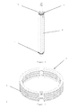
- Figure 1 illustrates an application of a collapsible clip 1 according to the present invention to a piezo-electric actuator assembly.
- a clip 1 is located at each end of the body of an actuator 5, over a sleeve 3 surrounding the body of the actuator 5, in order to seal the actuator 5 within the sleeve 3.
- FIGS 2 and 6 illustrate the clip 1 in an axially collapsed state.
- the clip 1 is in the form of a circular band and when the clip 1 is in an axially collapsed state the wall of the band is provided in an axial direction with a number of corrugations 7, having a sinusoidal cross-section profile in the radial direction, with internally facing peaks 8.
- Figure 5 shows the clip 1 in an axially extended state. In this state the depth or amplitude of the corrugations 7 is decreased and the internal diameter of the clip 1 is increased. The increase in the internal diameter of the clip 1 is proportional to the axial extension that the clip 1 is subjected to.
- the increased internal diameter of the clip 1 in the axially extended state enables the clip 1 to be fitted over the sleeve 3 surrounding the body of the actuator 5. Subsequent collapsing of the clip 1 into a collapsed state enables the ring seals to be formed between the clip 1, the sleeve 3 and the body of the actuator 5.
- the relaxed state of the clip 1 is the collapsed state.
- the material of the clip 1 remains within its elastic region.
- the clip 1 In axially stretching the clip 1 its internal diameter is increased such that it is larger than the external diameter of the sleeve 3, when the sleeve 3 is fitted over the ends 9,11 of the body of the actuator 5.
- the dimensions of the clip 1 and its corrugations 7 are chosen such that when the clip 1 is in its relaxed collapsed state the internal diameter of the clip is less than the external diameter of the sleeve 3, when the sleeve 3 is fitted over the ends 9,11 of the body of the actuator 5.
- the relaxed state of the clip 1 is the axially extended state.
- the internal diameter of the clip 1 is larger than the external diameter of the sleeve 3, when the sleeve 3 is fitted over the body of the actuator 5, to enable the clip to be located in position.
- a force is applied to the clip 1 to axially crush it.
- the material of the clip 1 is plastically deformed.
- the dimensions of the clip 1 are also chosen such that there is sufficient elastic margin from the state of the clip 1 when it has been fitted that efficient ring seals can be maintained even if the clamped material, for example the material of the sleeve 3, should creep or otherwise change cross-sectional thickness.
- the clip 1 may be manufactured as a single component. However, it may be advantageous, for example for manufacturing reasons, to manufacture the clip 1 as a number of parts, for assembly prior to fitting.
Landscapes
- Engineering & Computer Science (AREA)
- General Engineering & Computer Science (AREA)
- Mechanical Engineering (AREA)
- Fuel-Injection Apparatus (AREA)
- Mutual Connection Of Rods And Tubes (AREA)
- General Electrical Machinery Utilizing Piezoelectricity, Electrostriction Or Magnetostriction (AREA)
Abstract
Description
- The present invention relates to a clip for sealing the ends of a sleeve located around a piezo-electric actuator to the body of that piezo-electric actuator. In particular, the present invention relates to a collapsible clip having an internal dimension which decreases when the clip is axially collapsed.
- In a fuel injector the piezo-electric actuator may be located in an accumulator volume which receives high pressure fuel. It is essential to prevent contact between the fuel and the actuator to prevent the actuator from suffering damage. To prevent such damage it is known to provide a sleeve around the actuator. This sleeve must be sealed to the actuator at each end to prevent the ingress of fuel and any contaminants that it may contain.
- According to a first aspect the present invention provides a tubular clip for securing a sleeve to the body of a piezo-electric actuator in an actuator assembly, wherein, in use, the wall of the clip has a plurality of corrugations, with a pitch variable in the direction of the longitudinal axis of the clip, and the clip is configurable into an unfitted configuration and into a fitted configuration and in the fitted configuration the minimum transverse internal separation of the clip walls is less than in the unfitted configuration.
- Preferably, the clip has a circular cross-section. This is advantageous because the distribution of stress and force is mathematically uniform in the radial plane and thus provides a continuous and uniform radial sealing force where the corrugations are in contact with the sleeve. However, the band may be of any shape that is necessary to complement the external profile of the actuator body. For example, the band may be hexagonal.
- Preferably, the corrugations have a sinusoidal cross-sectional profile. This produces a preferred stress distribution within the clip because there are no stress raisers. In addition, the smooth peaks of the clip are less likely to induce a tear in the material of the sleeve. However, the cross-sectional profile of the corrugations may be of any form that facilitates collapsibility and efficient sealing, for example, the corrugations may have a triangular, sawtooth profile.
- Preferably, the clip is made from spring steel. This is advantageous because of the large elastic range of this material. Alternatively, the clip may be made from a shape memory alloy. This is advantageous because of the increased elastic range of this family of materials.
- According to a second aspect the present invention provides a method of fitting a clip to secure a sleeve to the body of a piezo-electric actuator in an actuator assembly, comprising the steps of applying a force to the clip when it is in the fitted configuration, the force elastically axially extending the clip from the fitted configuration to the unfitted configuration, fitting the clip over the sleeve surrounding the actuator, and removing the force from the clip so that it elastically reverts towards the fitted configuration, wherein the corrugations on the clip form a plurality of continuous ring seals around the sleeve and the body of the actuator, wherein the corrugations on the clip form a plurality of continuous ring seals around the sleeve and the body of the actuator.
- According to a third aspect the present invention provides a further method of fitting a clip to secure a sleeve to the body of a piezo-electric actuator in an actuator assembly, comprising the steps of, fitting the clip in the unfitted configuration over the sleeve surrounding the actuator, applying a force to the clip when it is in the unfitted configuration, the force plastically axially crushing the clip from the unfitted configuration to the fitted configuration, and removing the force from the clip, wherein the corrugations on the clip form a plurality of continuous ring seals around the sleeve and the body of the actuator.
- A preferred embodiment of the present invention will now be described with reference to the accompanying drawings in which:
-
Figure 1 is a perspective view of a piezo-electric actuator assembly provided with a protective sleeve which is sealed at either end to the body of the actuator by a collapsible clip according to the present invention; -
Figure 2 is a perspective view of the collapsible clip ofFigure 1 in an axially collapsed state; -
Figure 3 is a cross-sectional view of the piezo-electric actuator assembly showing a collapsible clip according to the present invention sealing the protective sleeve to a first end of the actuator body; -
Figure 4 is a cross-sectional view of the piezo-electric actuator assembly showing a collapsible clip according to the present invention sealing the protective sleeve to a second end of the actuator body; -
Figure 5 is an elevation view of the collapsible clip ofFigure 1 in an axially extended state; and -
Figure 6 is an elevation view of the collapsible clip ofFigure 1 in an axially collapsed state -
Figure 1 illustrates an application of acollapsible clip 1 according to the present invention to a piezo-electric actuator assembly. Aclip 1 is located at each end of the body of anactuator 5, over asleeve 3 surrounding the body of theactuator 5, in order to seal theactuator 5 within thesleeve 3. -
Figures 2 and6 illustrate theclip 1 in an axially collapsed state. Theclip 1 is in the form of a circular band and when theclip 1 is in an axially collapsed state the wall of the band is provided in an axial direction with a number ofcorrugations 7, having a sinusoidal cross-section profile in the radial direction, with internally facingpeaks 8. - As shown in
Figures 3 and 4 , when theclip 1 is applied to a piezo-electric actuator assembly the internally facingpeak 8 of each corrugation contacts theprotective sleeve 3 and forms a continuous ring seal between thesleeve 3 and therespective ends actuator 5. Theends circular clip 1. -
Figure 5 shows theclip 1 in an axially extended state. In this state the depth or amplitude of thecorrugations 7 is decreased and the internal diameter of theclip 1 is increased. The increase in the internal diameter of theclip 1 is proportional to the axial extension that theclip 1 is subjected to. - The increased internal diameter of the
clip 1 in the axially extended state enables theclip 1 to be fitted over thesleeve 3 surrounding the body of theactuator 5. Subsequent collapsing of theclip 1 into a collapsed state enables the ring seals to be formed between theclip 1, thesleeve 3 and the body of theactuator 5. - According to the present invention there are two preferred methods for transitioning the
clip 1 from an extended state to a collapsed state. - In the first embodiment the relaxed state of the
clip 1 is the collapsed state. In order to fit theclip 1 to the actuator assembly it is axially stretched. However, the material of theclip 1 remains within its elastic region. In axially stretching theclip 1 its internal diameter is increased such that it is larger than the external diameter of thesleeve 3, when thesleeve 3 is fitted over theends actuator 5. The dimensions of theclip 1 and itscorrugations 7 are chosen such that when theclip 1 is in its relaxed collapsed state the internal diameter of the clip is less than the external diameter of thesleeve 3, when thesleeve 3 is fitted over theends actuator 5. Thus, when theclip 1 is fitted to the actuator assembly it cannot fully return to its relaxed collapsed state and consequently thepeaks 8 of the corrugations apply a radial compressive force to thesleeve 3, in order to create the ring seals discussed above. - In the second embodiment the relaxed state of the
clip 1 is the axially extended state. In the axially extended state the internal diameter of theclip 1 is larger than the external diameter of thesleeve 3, when thesleeve 3 is fitted over the body of theactuator 5, to enable the clip to be located in position. In order to clamp theclip 1 to the actuator assembly a force is applied to theclip 1 to axially crush it. In this embodiment the material of theclip 1 is plastically deformed. In crushing theclip 1 its internal diameter is decreased to a size which is smaller than the external diameter of thesleeve 3, when thesleeve 3 is fitted over theends actuator 5, such that the ring seals discussed above can be created between thepeaks 8 of thecorrugations 7 and thesleeve 3. The dimensions of theclip 1 and itscorrugations 7 are chosen such that even if there is some elastic recovery of theclip 1 when the crushing force is released, the inner diameter of theclip 1 does not become larger than the external diameter of thesleeve 3 when fitted over theends actuator 5. This embodiment of the present invention may either use the material properties of theclip 1, or controlled buckling, to achieve the necessary plastic deformation. - In both the first and the second embodiments the dimensions of the
clip 1 are also chosen such that there is sufficient elastic margin from the state of theclip 1 when it has been fitted that efficient ring seals can be maintained even if the clamped material, for example the material of thesleeve 3, should creep or otherwise change cross-sectional thickness. - The
clip 1 may be manufactured as a single component. However, it may be advantageous, for example for manufacturing reasons, to manufacture theclip 1 as a number of parts, for assembly prior to fitting.
Claims (6)
- A tubular clip (1) for securing a sleeve (3) to the body of a piezo-electric actuator (5) in an actuator assembly, wherein, in use, the wall of the clip (1) has a plurality of corrugations (7), with a pitch variable in the direction of the longitudinal axis of the clip (1), and the clip (1) is configurable into an unfitted configuration and into a fitted configuration and in the fitted configuration the minimum transverse internal separation of the clip walls is less than in the unfitted configuration.
- A clip (1) as claimed in claim 1, having a circular cross-section.
- A clip (1) as claimed in claim 1 or claim 2, wherein the corrugations (7) have a sinusoidal cross-sectional profile.
- A clip (1) as claimed in any one of claims 1, 2 or 3, made from spring steel.
- A method of fitting a clip (1) according to any preceding claim to secure a sleeve (3) to the body of a piezo-electric actuator (5) in an actuator assembly comprising the steps of applying a force to the clip (1) when it is in the fitted configuration, the force elastically axially extending the clip (1) from the fitted configuration to the axially extended unfitted configuration, fitting the clip (1) over the sleeve surrounding the actuator (5), and removing the force from the clip (1) so that it elastically reverts towards the fitted configuration.
- A method of fitting a clip (1) according to any one of claims 1 to 4 to secure a sleeve (3) to the body of a piezo-electric actuator (5) in an actuator assembly comprising the steps of fitting the clip (1) in the unfitted configuration over the sleeve (3) surrounding the actuator (5), applying a force to the clip (1) when it is in the unfitted configuration, the force plastically axially crushing the clip (1) from the unfitted configuration to the fitted configuration, and removing the force from the clip (1).
Applications Claiming Priority (1)
| Application Number | Priority Date | Filing Date | Title |
|---|---|---|---|
| GBGB0711557.9A GB0711557D0 (en) | 2007-06-15 | 2007-06-15 | A collapsible clip |
Publications (3)
| Publication Number | Publication Date |
|---|---|
| EP2014966A2 true EP2014966A2 (en) | 2009-01-14 |
| EP2014966A3 EP2014966A3 (en) | 2010-07-14 |
| EP2014966B1 EP2014966B1 (en) | 2013-10-23 |
Family
ID=38332136
Family Applications (1)
| Application Number | Title | Priority Date | Filing Date |
|---|---|---|---|
| EP08157882.5A Active EP2014966B1 (en) | 2007-06-15 | 2008-06-09 | Methods of fitting a clip to secure a sleeve to the body of a piezo electric actuator |
Country Status (4)
| Country | Link |
|---|---|
| US (1) | US8973227B2 (en) |
| EP (1) | EP2014966B1 (en) |
| JP (1) | JP5022996B2 (en) |
| GB (1) | GB0711557D0 (en) |
Cited By (2)
| Publication number | Priority date | Publication date | Assignee | Title |
|---|---|---|---|---|
| EP2343746A1 (en) | 2010-01-11 | 2011-07-13 | Delphi Technologies Holding S.à.r.l. | Method of Encapsulating an Actuator having a Piezoelectric Actuator Stack |
| EP2372139A1 (en) * | 2010-03-25 | 2011-10-05 | Delphi Technologies Holding S.à.r.l. | Actuator Arrangement for use in a Fuel Injector |
Families Citing this family (1)
| Publication number | Priority date | Publication date | Assignee | Title |
|---|---|---|---|---|
| ATE525756T1 (en) * | 2008-01-30 | 2011-10-15 | Delphi Tech Holding Sarl | CLAMP |
Family Cites Families (6)
| Publication number | Priority date | Publication date | Assignee | Title |
|---|---|---|---|---|
| JPS5563415U (en) * | 1978-10-25 | 1980-04-30 | ||
| EP0131874A1 (en) * | 1983-07-13 | 1985-01-23 | INDUSTRIE PIRELLI S.p.A. | Blocking element for acting as a seal between the end part of a hose and a rigid internal core |
| JP2508383B2 (en) * | 1990-08-27 | 1996-06-19 | 株式会社村田製作所 | Angular velocity sensor |
| DE19533553C2 (en) * | 1995-09-11 | 1998-01-29 | Rasmussen Gmbh | Device for clamping a hose end section pushed onto a pipe end section |
| DE10061425A1 (en) * | 2000-12-09 | 2002-06-13 | Bayerische Motoren Werke Ag | System for attaching elastomeric hose to connector comprises press-fitting or clamp and locking component nearer end of hose which presses hose radially against connector, even at temperatures below freezing point of elastomer |
| ES2298960T3 (en) * | 2005-11-04 | 2008-05-16 | Delphi Technologies, Inc. | PROVISION OF DRIVING DEVICE. |
-
2007
- 2007-06-15 GB GBGB0711557.9A patent/GB0711557D0/en not_active Ceased
-
2008
- 2008-06-09 EP EP08157882.5A patent/EP2014966B1/en active Active
- 2008-06-12 JP JP2008153642A patent/JP5022996B2/en not_active Expired - Fee Related
- 2008-06-13 US US12/157,859 patent/US8973227B2/en not_active Expired - Fee Related
Cited By (3)
| Publication number | Priority date | Publication date | Assignee | Title |
|---|---|---|---|---|
| EP2343746A1 (en) | 2010-01-11 | 2011-07-13 | Delphi Technologies Holding S.à.r.l. | Method of Encapsulating an Actuator having a Piezoelectric Actuator Stack |
| WO2011082843A1 (en) | 2010-01-11 | 2011-07-14 | Delphi Technologies Holding S.A.R.L. | Method of encapsulating an actuator having a piezoelectric actuator stack |
| EP2372139A1 (en) * | 2010-03-25 | 2011-10-05 | Delphi Technologies Holding S.à.r.l. | Actuator Arrangement for use in a Fuel Injector |
Also Published As
| Publication number | Publication date |
|---|---|
| EP2014966B1 (en) | 2013-10-23 |
| EP2014966A3 (en) | 2010-07-14 |
| JP2009044132A (en) | 2009-02-26 |
| GB0711557D0 (en) | 2007-07-25 |
| US20080307616A1 (en) | 2008-12-18 |
| JP5022996B2 (en) | 2012-09-12 |
| US8973227B2 (en) | 2015-03-10 |
Similar Documents
| Publication | Publication Date | Title |
|---|---|---|
| CN103917816B (en) | pipe connector | |
| CN101421060B (en) | How to join components | |
| US20190145486A1 (en) | Interference Arrangement for Spring | |
| WO2012105525A1 (en) | Tube joint | |
| JP5556624B2 (en) | Piping joint | |
| US20100194099A1 (en) | Clamp fitting for a pipe | |
| GB2212579A (en) | Clamping ring pipe connection for metallic pipes | |
| EP2758701B1 (en) | Hose clamp | |
| EP2014966B1 (en) | Methods of fitting a clip to secure a sleeve to the body of a piezo electric actuator | |
| JP5805392B2 (en) | Hoop-type retaining ring | |
| EP3217044B1 (en) | Metal bellows | |
| WO2002070940A1 (en) | Coupling for connection of a tube or hose by pushing-in | |
| CN106884917A (en) | Antihunting device | |
| JP5049842B2 (en) | Stabilizer bush | |
| KR101634507B1 (en) | Coupling and coupling assembly | |
| US7675223B2 (en) | Clip | |
| JP4437080B2 (en) | Hydropower accumulator | |
| JP6207310B2 (en) | Dust cover | |
| JP2006336865A (en) | Bellows for joint | |
| EP1956278A1 (en) | Coupling | |
| JP5964200B2 (en) | Rebound rubber | |
| JP2018052014A (en) | Strip-shaped member for spiral tube formation | |
| KR200255542Y1 (en) | a pipe joint with an insert | |
| US8347505B2 (en) | Method for fabricating a cylindrical spring by compressive force | |
| CN113446448B (en) | Bellows connecting device |
Legal Events
| Date | Code | Title | Description |
|---|---|---|---|
| PUAI | Public reference made under article 153(3) epc to a published international application that has entered the european phase |
Free format text: ORIGINAL CODE: 0009012 |
|
| PUAI | Public reference made under article 153(3) epc to a published international application that has entered the european phase |
Free format text: ORIGINAL CODE: 0009012 |
|
| AK | Designated contracting states |
Kind code of ref document: A2 Designated state(s): AT BE BG CH CY CZ DE DK EE ES FI FR GB GR HR HU IE IS IT LI LT LU LV MC MT NL NO PL PT RO SE SI SK TR |
|
| AX | Request for extension of the european patent |
Extension state: AL BA MK RS |
|
| RAP1 | Party data changed (applicant data changed or rights of an application transferred) |
Owner name: DELPHI TECHNOLOGIES HOLDING S.A.R.L. |
|
| PUAL | Search report despatched |
Free format text: ORIGINAL CODE: 0009013 |
|
| AK | Designated contracting states |
Kind code of ref document: A3 Designated state(s): AT BE BG CH CY CZ DE DK EE ES FI FR GB GR HR HU IE IS IT LI LT LU LV MC MT NL NO PL PT RO SE SI SK TR |
|
| AX | Request for extension of the european patent |
Extension state: AL BA MK RS |
|
| 17P | Request for examination filed |
Effective date: 20110114 |
|
| AKX | Designation fees paid |
Designated state(s): AT BE BG CH CY CZ DE DK EE ES FI FR GB GR HR HU IE IS IT LI LT LU LV MC MT NL NO PL PT RO SE SI SK TR |
|
| AXX | Extension fees paid |
Extension state: MK Payment date: 20110114 Extension state: RS Payment date: 20110114 Extension state: BA Payment date: 20110114 Extension state: AL Payment date: 20110114 |
|
| GRAP | Despatch of communication of intention to grant a patent |
Free format text: ORIGINAL CODE: EPIDOSNIGR1 |
|
| INTG | Intention to grant announced |
Effective date: 20130705 |
|
| GRAS | Grant fee paid |
Free format text: ORIGINAL CODE: EPIDOSNIGR3 |
|
| GRAA | (expected) grant |
Free format text: ORIGINAL CODE: 0009210 |
|
| AK | Designated contracting states |
Kind code of ref document: B1 Designated state(s): AT BE BG CH CY CZ DE DK EE ES FI FR GB GR HR HU IE IS IT LI LT LU LV MC MT NL NO PL PT RO SE SI SK TR |
|
| AX | Request for extension of the european patent |
Extension state: AL BA MK RS |
|
| REG | Reference to a national code |
Ref country code: GB Ref legal event code: FG4D |
|
| REG | Reference to a national code |
Ref country code: CH Ref legal event code: EP |
|
| REG | Reference to a national code |
Ref country code: AT Ref legal event code: REF Ref document number: 637798 Country of ref document: AT Kind code of ref document: T Effective date: 20131115 |
|
| REG | Reference to a national code |
Ref country code: IE Ref legal event code: FG4D |
|
| REG | Reference to a national code |
Ref country code: DE Ref legal event code: R096 Ref document number: 602008028253 Country of ref document: DE Effective date: 20131219 |
|
| REG | Reference to a national code |
Ref country code: NL Ref legal event code: VDEP Effective date: 20131023 |
|
| REG | Reference to a national code |
Ref country code: AT Ref legal event code: MK05 Ref document number: 637798 Country of ref document: AT Kind code of ref document: T Effective date: 20131023 |
|
| RAP2 | Party data changed (patent owner data changed or rights of a patent transferred) |
Owner name: DELPHI INTERNATIONAL OPERATIONS LUXEMBOURG S.A.R.L |
|
| REG | Reference to a national code |
Ref country code: LT Ref legal event code: MG4D |
|
| PG25 | Lapsed in a contracting state [announced via postgrant information from national office to epo] |
Ref country code: NL Free format text: LAPSE BECAUSE OF FAILURE TO SUBMIT A TRANSLATION OF THE DESCRIPTION OR TO PAY THE FEE WITHIN THE PRESCRIBED TIME-LIMIT Effective date: 20131023 Ref country code: HR Free format text: LAPSE BECAUSE OF FAILURE TO SUBMIT A TRANSLATION OF THE DESCRIPTION OR TO PAY THE FEE WITHIN THE PRESCRIBED TIME-LIMIT Effective date: 20131023 Ref country code: SE Free format text: LAPSE BECAUSE OF FAILURE TO SUBMIT A TRANSLATION OF THE DESCRIPTION OR TO PAY THE FEE WITHIN THE PRESCRIBED TIME-LIMIT Effective date: 20131023 Ref country code: LT Free format text: LAPSE BECAUSE OF FAILURE TO SUBMIT A TRANSLATION OF THE DESCRIPTION OR TO PAY THE FEE WITHIN THE PRESCRIBED TIME-LIMIT Effective date: 20131023 Ref country code: FI Free format text: LAPSE BECAUSE OF FAILURE TO SUBMIT A TRANSLATION OF THE DESCRIPTION OR TO PAY THE FEE WITHIN THE PRESCRIBED TIME-LIMIT Effective date: 20131023 Ref country code: NO Free format text: LAPSE BECAUSE OF FAILURE TO SUBMIT A TRANSLATION OF THE DESCRIPTION OR TO PAY THE FEE WITHIN THE PRESCRIBED TIME-LIMIT Effective date: 20140123 Ref country code: BE Free format text: LAPSE BECAUSE OF FAILURE TO SUBMIT A TRANSLATION OF THE DESCRIPTION OR TO PAY THE FEE WITHIN THE PRESCRIBED TIME-LIMIT Effective date: 20131023 Ref country code: IS Free format text: LAPSE BECAUSE OF FAILURE TO SUBMIT A TRANSLATION OF THE DESCRIPTION OR TO PAY THE FEE WITHIN THE PRESCRIBED TIME-LIMIT Effective date: 20140223 |
|
| PG25 | Lapsed in a contracting state [announced via postgrant information from national office to epo] |
Ref country code: CY Free format text: LAPSE BECAUSE OF FAILURE TO SUBMIT A TRANSLATION OF THE DESCRIPTION OR TO PAY THE FEE WITHIN THE PRESCRIBED TIME-LIMIT Effective date: 20131023 Ref country code: LV Free format text: LAPSE BECAUSE OF FAILURE TO SUBMIT A TRANSLATION OF THE DESCRIPTION OR TO PAY THE FEE WITHIN THE PRESCRIBED TIME-LIMIT Effective date: 20131023 Ref country code: ES Free format text: LAPSE BECAUSE OF FAILURE TO SUBMIT A TRANSLATION OF THE DESCRIPTION OR TO PAY THE FEE WITHIN THE PRESCRIBED TIME-LIMIT Effective date: 20131023 Ref country code: AT Free format text: LAPSE BECAUSE OF FAILURE TO SUBMIT A TRANSLATION OF THE DESCRIPTION OR TO PAY THE FEE WITHIN THE PRESCRIBED TIME-LIMIT Effective date: 20131023 |
|
| REG | Reference to a national code |
Ref country code: FR Ref legal event code: TP Owner name: DELPHI INTERNATIONAL OPERATIONS LUXEMBOURG S.A, LU Effective date: 20140516 |
|
| PG25 | Lapsed in a contracting state [announced via postgrant information from national office to epo] |
Ref country code: PT Free format text: LAPSE BECAUSE OF FAILURE TO SUBMIT A TRANSLATION OF THE DESCRIPTION OR TO PAY THE FEE WITHIN THE PRESCRIBED TIME-LIMIT Effective date: 20140224 |
|
| REG | Reference to a national code |
Ref country code: DE Ref legal event code: R097 Ref document number: 602008028253 Country of ref document: DE |
|
| REG | Reference to a national code |
Ref country code: HU Ref legal event code: AG4A Ref document number: E019797 Country of ref document: HU Ref country code: HU Ref legal event code: GB9C Owner name: DELPHI INTERNATIONAL OPERATIONS LUXEMBOURG S.A, LU Free format text: FORMER OWNER(S): DELPHI TECHNOLOGIES HOLDING S.A.R.L., LU |
|
| PG25 | Lapsed in a contracting state [announced via postgrant information from national office to epo] |
Ref country code: EE Free format text: LAPSE BECAUSE OF FAILURE TO SUBMIT A TRANSLATION OF THE DESCRIPTION OR TO PAY THE FEE WITHIN THE PRESCRIBED TIME-LIMIT Effective date: 20131023 |
|
| REG | Reference to a national code |
Ref country code: DE Ref legal event code: R081 Ref document number: 602008028253 Country of ref document: DE Owner name: DELPHI INTERNATIONAL OPERATIONS LUXEMBOURG S.A, LU Free format text: FORMER OWNER: DELPHI TECHNOLOGIES HOLDING S.A.R.L., BASCHARAGE, LU Effective date: 20140702 |
|
| PG25 | Lapsed in a contracting state [announced via postgrant information from national office to epo] |
Ref country code: CZ Free format text: LAPSE BECAUSE OF FAILURE TO SUBMIT A TRANSLATION OF THE DESCRIPTION OR TO PAY THE FEE WITHIN THE PRESCRIBED TIME-LIMIT Effective date: 20131023 Ref country code: PL Free format text: LAPSE BECAUSE OF FAILURE TO SUBMIT A TRANSLATION OF THE DESCRIPTION OR TO PAY THE FEE WITHIN THE PRESCRIBED TIME-LIMIT Effective date: 20131023 Ref country code: SK Free format text: LAPSE BECAUSE OF FAILURE TO SUBMIT A TRANSLATION OF THE DESCRIPTION OR TO PAY THE FEE WITHIN THE PRESCRIBED TIME-LIMIT Effective date: 20131023 Ref country code: RO Free format text: LAPSE BECAUSE OF FAILURE TO SUBMIT A TRANSLATION OF THE DESCRIPTION OR TO PAY THE FEE WITHIN THE PRESCRIBED TIME-LIMIT Effective date: 20131023 |
|
| PLBE | No opposition filed within time limit |
Free format text: ORIGINAL CODE: 0009261 |
|
| STAA | Information on the status of an ep patent application or granted ep patent |
Free format text: STATUS: NO OPPOSITION FILED WITHIN TIME LIMIT |
|
| PG25 | Lapsed in a contracting state [announced via postgrant information from national office to epo] |
Ref country code: DK Free format text: LAPSE BECAUSE OF FAILURE TO SUBMIT A TRANSLATION OF THE DESCRIPTION OR TO PAY THE FEE WITHIN THE PRESCRIBED TIME-LIMIT Effective date: 20131023 |
|
| 26N | No opposition filed |
Effective date: 20140724 |
|
| REG | Reference to a national code |
Ref country code: DE Ref legal event code: R097 Ref document number: 602008028253 Country of ref document: DE Effective date: 20140724 |
|
| PG25 | Lapsed in a contracting state [announced via postgrant information from national office to epo] |
Ref country code: MC Free format text: LAPSE BECAUSE OF FAILURE TO SUBMIT A TRANSLATION OF THE DESCRIPTION OR TO PAY THE FEE WITHIN THE PRESCRIBED TIME-LIMIT Effective date: 20131023 Ref country code: LU Free format text: LAPSE BECAUSE OF FAILURE TO SUBMIT A TRANSLATION OF THE DESCRIPTION OR TO PAY THE FEE WITHIN THE PRESCRIBED TIME-LIMIT Effective date: 20140609 |
|
| REG | Reference to a national code |
Ref country code: CH Ref legal event code: PL |
|
| GBPC | Gb: european patent ceased through non-payment of renewal fee |
Effective date: 20140609 |
|
| PG25 | Lapsed in a contracting state [announced via postgrant information from national office to epo] |
Ref country code: SI Free format text: LAPSE BECAUSE OF FAILURE TO SUBMIT A TRANSLATION OF THE DESCRIPTION OR TO PAY THE FEE WITHIN THE PRESCRIBED TIME-LIMIT Effective date: 20131023 |
|
| REG | Reference to a national code |
Ref country code: IE Ref legal event code: MM4A |
|
| PG25 | Lapsed in a contracting state [announced via postgrant information from national office to epo] |
Ref country code: CH Free format text: LAPSE BECAUSE OF NON-PAYMENT OF DUE FEES Effective date: 20140630 Ref country code: LI Free format text: LAPSE BECAUSE OF NON-PAYMENT OF DUE FEES Effective date: 20140630 Ref country code: IE Free format text: LAPSE BECAUSE OF NON-PAYMENT OF DUE FEES Effective date: 20140609 |
|
| PG25 | Lapsed in a contracting state [announced via postgrant information from national office to epo] |
Ref country code: GB Free format text: LAPSE BECAUSE OF NON-PAYMENT OF DUE FEES Effective date: 20140609 |
|
| REG | Reference to a national code |
Ref country code: FR Ref legal event code: PLFP Year of fee payment: 8 |
|
| PGFP | Annual fee paid to national office [announced via postgrant information from national office to epo] |
Ref country code: DE Payment date: 20150629 Year of fee payment: 8 |
|
| PGFP | Annual fee paid to national office [announced via postgrant information from national office to epo] |
Ref country code: HU Payment date: 20150527 Year of fee payment: 8 Ref country code: FR Payment date: 20150617 Year of fee payment: 8 |
|
| PGFP | Annual fee paid to national office [announced via postgrant information from national office to epo] |
Ref country code: IT Payment date: 20150625 Year of fee payment: 8 |
|
| PG25 | Lapsed in a contracting state [announced via postgrant information from national office to epo] |
Ref country code: MT Free format text: LAPSE BECAUSE OF FAILURE TO SUBMIT A TRANSLATION OF THE DESCRIPTION OR TO PAY THE FEE WITHIN THE PRESCRIBED TIME-LIMIT Effective date: 20131023 |
|
| PG25 | Lapsed in a contracting state [announced via postgrant information from national office to epo] |
Ref country code: BG Free format text: LAPSE BECAUSE OF FAILURE TO SUBMIT A TRANSLATION OF THE DESCRIPTION OR TO PAY THE FEE WITHIN THE PRESCRIBED TIME-LIMIT Effective date: 20131023 |
|
| PG25 | Lapsed in a contracting state [announced via postgrant information from national office to epo] |
Ref country code: GR Free format text: LAPSE BECAUSE OF FAILURE TO SUBMIT A TRANSLATION OF THE DESCRIPTION OR TO PAY THE FEE WITHIN THE PRESCRIBED TIME-LIMIT Effective date: 20140124 |
|
| PG25 | Lapsed in a contracting state [announced via postgrant information from national office to epo] |
Ref country code: TR Free format text: LAPSE BECAUSE OF FAILURE TO SUBMIT A TRANSLATION OF THE DESCRIPTION OR TO PAY THE FEE WITHIN THE PRESCRIBED TIME-LIMIT Effective date: 20131023 |
|
| REG | Reference to a national code |
Ref country code: DE Ref legal event code: R119 Ref document number: 602008028253 Country of ref document: DE |
|
| REG | Reference to a national code |
Ref country code: FR Ref legal event code: ST Effective date: 20170228 |
|
| PG25 | Lapsed in a contracting state [announced via postgrant information from national office to epo] |
Ref country code: HU Free format text: LAPSE BECAUSE OF NON-PAYMENT OF DUE FEES Effective date: 20160610 Ref country code: FR Free format text: LAPSE BECAUSE OF NON-PAYMENT OF DUE FEES Effective date: 20160630 Ref country code: DE Free format text: LAPSE BECAUSE OF NON-PAYMENT OF DUE FEES Effective date: 20170103 |
|
| PG25 | Lapsed in a contracting state [announced via postgrant information from national office to epo] |
Ref country code: IT Free format text: LAPSE BECAUSE OF NON-PAYMENT OF DUE FEES Effective date: 20160609 |