EP2020492A1 - Drosselventil - Google Patents
Drosselventil Download PDFInfo
- Publication number
- EP2020492A1 EP2020492A1 EP08161477A EP08161477A EP2020492A1 EP 2020492 A1 EP2020492 A1 EP 2020492A1 EP 08161477 A EP08161477 A EP 08161477A EP 08161477 A EP08161477 A EP 08161477A EP 2020492 A1 EP2020492 A1 EP 2020492A1
- Authority
- EP
- European Patent Office
- Prior art keywords
- throttle valve
- throttle
- pivot axis
- actuator
- control
- Prior art date
- Legal status (The legal status is an assumption and is not a legal conclusion. Google has not performed a legal analysis and makes no representation as to the accuracy of the status listed.)
- Granted
Links
- 229920001971 elastomer Polymers 0.000 claims abstract description 5
- 239000000806 elastomer Substances 0.000 claims abstract description 5
- 238000002485 combustion reaction Methods 0.000 claims description 5
- 238000007789 sealing Methods 0.000 claims description 3
- 238000009434 installation Methods 0.000 claims 1
- 230000000903 blocking effect Effects 0.000 description 2
- 101001017827 Mus musculus Leucine-rich repeat flightless-interacting protein 1 Proteins 0.000 description 1
- 230000008014 freezing Effects 0.000 description 1
- 238000007710 freezing Methods 0.000 description 1
- 239000000446 fuel Substances 0.000 description 1
- 238000004519 manufacturing process Methods 0.000 description 1
- 238000000034 method Methods 0.000 description 1
- 230000001105 regulatory effect Effects 0.000 description 1
- 238000010079 rubber tapping Methods 0.000 description 1
Images

Classifications
-
- F—MECHANICAL ENGINEERING; LIGHTING; HEATING; WEAPONS; BLASTING
- F02—COMBUSTION ENGINES; HOT-GAS OR COMBUSTION-PRODUCT ENGINE PLANTS
- F02D—CONTROLLING COMBUSTION ENGINES
- F02D9/00—Controlling engines by throttling air or fuel-and-air induction conduits or exhaust conduits
- F02D9/08—Throttle valves specially adapted therefor; Arrangements of such valves in conduits
- F02D9/10—Throttle valves specially adapted therefor; Arrangements of such valves in conduits having pivotally-mounted flaps
- F02D9/1065—Mechanical control linkage between an actuator and the flap, e.g. including levers, gears, springs, clutches, limit stops of the like
Definitions
- the present invention is a throttle valve, which is installed in an air intake pipe of an internal combustion engine of a motor vehicle.
- the object of such throttle valves is to regulate the volume of air which is to be supplied to the engine for the combustion of the fuel.
- a disk-shaped throttle which is pivotally mounted in a throttle housing about a pivot axis and an electric actuator which cooperates with a position sensor to control the pivoting movement of the throttle valve.
- the flow area of the intake pipe is between zero, i. the closing position of the throttle, and a maximum value regulated.
- the conventional throttle valves currently available on the market correspond to hyperstatic systems, which are prone to freezing up to blocking especially the bearings on which the swivel axis of the throttle valve is mounted.
- the object of the present invention is to remedy this disadvantage.
- a throttle valve of the above type which includes connecting means with which a mechanical decoupling can be performed, similar to a Cardan joint, between the output shaft of the actuator or control axis and the pivot axis of the throttle valve.
- such connecting means preferably consist of a shift linkage, which is connected in each case with the control axis and the pivot axis of the throttle valve at its outer ends by means of a ball and socket joint.
- This decoupling of both the control axis and the pivot axis of the throttle valve is particularly advantageous because it allows to prevent the eaters of the pivot axis in the camps by compensating for any deformations due to mounting tolerances, vibrations, temperature fluctuations, etc.
- the connecting linkage includes two spherical cavities which form the female parts of the ball joint and whose associated male parts are fixedly connected respectively to the control axis and the pivot axis of the throttle valve.
- the swivel axis of the throttle valve can be equipped with a substantially cylindrical drive element, on which a return spring is mounted, with which the throttle valve can be automatically returned to its closed position, without the external loads acting on them.
- the male part of the ball-and-socket joint connected to this pivot axis can also preferably be mounted on such a drive element.
- the actuator is connected via the connecting means directly to the throttle valve.
- the object of the present invention is likewise to remedy this disadvantage.
- the throttle valve is made of a plastic element coated with an elastomer defining the sealing lips on its periphery.
- This elastomer gives the throttle an elasticity that virtually eliminates leaks in the closed position.
- Another advantage is the noise reduction with a quick closing of the throttle.
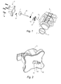
- FIG. 1 is an exploded perspective view of the main elements that make up this valve
- FIG. 2 represents the housing of the actuator
- FIG. 3 represents the pivot axis of the throttle
- FIGS. 4a and 4b each represent the lower and upper view of the kausschaltgestfites.
- the throttle valve consists essentially of a disc-shaped throttle valve 1, which is mounted on a throttle housing 2, which is fixed to the inner region of the intake manifold of an internal combustion engine, and of an electric actuator, not shown in the figures, which in the interior of an in FIG. 2 Actuator housing 3 shown in more detail is installed.
- the actuator housing 3 is attached laterally to the throttle housing 2 by means of tapping screws 4.
- the throttle valve 1 consists of a disc-shaped plastic element which is coated with an elastomer which defines the sealing lips 5 at its periphery.
- the throttle valve 1 is pivotally mounted about a pivot axis 6, which in FIG. 3 is shown in more detail.
- the swinging movement of the throttle valve 1 can be controlled between a closing position in which it blocks the air supply into the intake pipe of the engine and an opening position in which the flow area is set to a maximum value this will be described in more detail below.
- the pivot axis 6 of the throttle valve 1 is provided at its end opposite the actuator housing 3 with a substantially cylindrical drive element 7, on which a return spring 8 is mounted.
- the pivot axis 6 and the throttle valve 1 are mounted in the interior of the throttle body 2 on the bearings 9, 9 'with a seal 10 as an intermediate piece.
- FIGS. 1, 2 . 4a and 4b can be mechanically decoupled with a connecting linkage 11, the pivot axis 6 of the throttle valve 1 and the output shaft 12 from the actuator, which forms the control axis of this valve 1.
- the actuator is thus connected via the connecting linkage 11 directly to the throttle without further drive units are interposed therebetween.
- a position sensor not shown in the figures recognizes the actual angular position of the throttle valve 1 at all times and cooperates with the actuator to control the pivoting movement of this flap 1 about its pivot axis 6.
- the connecting linkage 11 is provided at its ends with two spherical cavities 13, 14 which form the female part of a ball and socket joint.
- the male part associated with the spherical cavity 13 is a ball and socket joint 15 mounted on a fitting 16 fixedly connected to the output shaft 12 of the actuator.
- FIG. 3 is the spherical cavity 14 associated male part of a ball joint 17, which is mounted on the outer circumference of the drive element 7 of the pivot axis 6 of the throttle valve 1.
Landscapes
- Engineering & Computer Science (AREA)
- Chemical & Material Sciences (AREA)
- Combustion & Propulsion (AREA)
- Mechanical Engineering (AREA)
- General Engineering & Computer Science (AREA)
- Control Of Throttle Valves Provided In The Intake System Or In The Exhaust System (AREA)
Abstract
Description
- Gegenstand der vorliegenden Erfindung ist ein Drosselventil, welches in ein Luftansaugrohr eines Verbrennungsmotors von einem Kraftfahrzeug eingebaut wird.
- Die Aufgabe derartiger Drosselventile ist es, das Luftvolumen zu regulieren, welches dem Motor für die Verbrennung des Kraftstoffs zugeführt werden soll.
- Herkömmlicherweise beinhalten sie eine scheibenförmige Drosselklappe, welche in einem Drosselgehäuse schwenkbar um eine Schwenkachse montiert ist, sowie einen elektrischen Aktuator, der mit einem Positionssensor zusammenarbeitet, um die Schwenkbewegung der Drosselklappe zu steuern.
- Mit dieser Schwenkbewegung wird der Strömungsquerschnitt des Ansaugrohrs zwischen Null, d.h. der Schließposition der Drosselklappe, und einem Maximalwert reguliert.
- Die zurzeit auf dem Markt angebotenen herkömmlichen Drosselventile entsprechen hyperstatischen Systemen, die anfällig sind für Fresser bis hin zum Blockieren vor allem der Lager, auf denen die Schwenkachse der Drosselklappe gelagert ist.
- Derartige Erscheinungen resultieren aus Verformungen als Folge von Belastungen, Vibrationen oder Temperaturschwankungen oder auch als Folge einer unzureichenden Dimensionseinstellung.
- Sie machen sich umso häufiger bemerkbar je stärker die in den Verbrennungsmotoren herrschende Temperatur Schwankungen aufgrund der Betriebsbedingungen und der klimatischen Bedingungen unterworfen ist, was dem Betrieb der Fahrzeuge außerordentlich schadet.
- Gegenstand der vorliegenden Erfindung ist es, diesen Nachteil zu beheben.
- Zu diesem Zweck stellt sie ein Drosselventil des oben genannten Typs bereit, welches Verbindungsmittel beinhaltet, mit denen eine mechanische Entkopplung durchgeführt werden kann, ähnlich wie bei einem Kardangelenk, zwischen der Abgangswelle des Aktuators oder Steuerachse und der Schwenkachse der Drosselklappe.
- Gemäß der Erfindung bestehen derartige Verbindungsmittel vorzugsweise aus einem Schaltgestänge, das jeweils mit der Steuerachse und der Schwenkachse der Drosselklappe an deren äußeren Enden mittels eines Kugelkopfgelenks verbunden ist.
- Diese Entkopplung sowohl der Steuerachse als auch der Schwenkachse der Drosselklappe ist insbesondere vorteilhaft, da sie es erlaubt, die Fresser der Schwenkachse in den Lagern zu verhindern, indem sie eventuelle Verformungen aufgrund von Montagetoleranzen, von Vibrationen, von Temperaturschwankungen usw. kompensiert.
- Gemäß eines weiteren Merkmals der Erfindung beinhaltet das Verbindungsschaltgestänge zwei kugelförmige Hohlräume, welche die weiblichen Teile des Kugelkopfgelenks bilden, und dessen dazugehörige männliche Teile jeweils mit der Steuerachse und der Schwenkachse der Drosselklappe fest verbunden sind.
- Wie bereits bekannt, kann die Schwenkachse der Drosselklappe mit einem im Wesentlichen zylindrischen Antriebselement ausgestattet werden, auf das eine Rückstellfeder montiert ist, mit der die Drosselklappe automatisch in ihre Schließposition zurückgeführt werden kann, ohne das äußere Belastungen auf sie einwirken.
- Gemäß der Erfindung kann das männliche Teil des mit dieser Schwenkachse verbundenen Kugelkopfgelenks ebenfalls vorzugsweise auf ein derartiges Antriebselement montiert werden.
- Gemäß eines weiteren Merkmals der Erfindung ist der Aktuator über die Verbindungsmittel direkt mit der Drosselklappe verbunden.
- Mit einer derartigen Konfiguration des Drosselventils gemäß der Erfindung kann der Montageprozess des Aktuators weitgehend vereinfacht werden, weil keine zusätzliche Antriebseinheit vorhanden ist.
- Gleichzeitig erlaubt sie es, die Gesamtkosten für das Drosselventil nennenswert zu senken, das nur wenige Teile enthält und außerdem eine größere Toleranzbreite bei der Herstellung erlaubt.
- Die zurzeit auf dem Markt angebotenen herkömmlichen Drosselventile haben ebenfalls den Nachteil, dass starke Leckagen auftreten können, wenn die Drosselklappe in Schließposition ist.
- Diese Leckagen sind insbesondere die Folge von Verformungen aufgrund von Temperaturschwankungen oder einer Erhöhung oder Verringerung des Drucks.
- Gegenstand der vorliegenden Erfindung ist es ebenfalls, diesen Nachteil zu beheben.
- Zu diesem Zweck und gemäß eines weiteren bevorzugten Merkmals dieser Erfindung besteht die Drosselklappe aus einem Kunststoffelement, das mit einem Elastomer beschichtet ist, welches die Dichtungslippen an ihrem Umfang definiert.
- Dieses Elastomer verleiht der Drosselklappe eine Elastizität, die praktisch Leckagen in Schließposition ausschließt.
- Ein weiterer Vorteil ist die Lärmreduzierung bei einem schnellen Schließen der Drosselklappe.
- Die Merkmale des Drosselventils, das Gegenstand der Erfindung ist, werden detaillierter erklärt unter Bezugnahme auf die nicht einschränkenden, beigefügten Zeichnungen, in denen
-
Figur 1 eine perspektivische Explosionsansicht der wichtigsten Elemente darstellt, aus denen dieses Ventil besteht, -
Figur 2 das Gehäuse des Aktuators darstellt, -
Figur 3 die Schwenkachse der Drosselklappe darstellt, - die
Figuren 4a und 4b jeweils die Unter- und Oberansicht des Verbindungsschaltgestänges darstellen. - Gemäß
Figur 1 besteht das Drosselventil im Wesentlichen aus einer scheibenförmigen Drosselklappe 1, die auf ein Drosselgehäuse 2 montiert ist, welches am Innenbereich des Ansaugrohrs eines Verbrennungsmotors befestigt ist, sowie aus einem nicht in den Figuren dargestellten elektrischen Aktuator, welcher im Innenbereich eines inFigur 2 näher dargestellten Aktuatorgehäuses 3 eingebaut ist. - Das Aktuatorgehäuse 3 ist seitlich am Drosselgehäuse 2 mittels Blechschrauben 4 befestigt.
- Die Drosselklappe 1 besteht aus einem scheibenförmigen Kunststoffelement, das mit einem Elastomer beschichtet ist, welches die Dichtungslippen 5 an ihrem Umfang definiert.
- Die Drosselklappe 1 ist schwenkbar um eine Schwenkachse 6 montiert, die in
Figur 3 detaillierter dargestellt ist. - Mit dem im Innenbereich des Aktuatorgehäuses 3 eingebauten elektrischen Aktuator kann die Schwenkbewegung der Drosselklappe 1 zwischen einer Schließposition, in welcher sie die Luftzufuhr in das Ansaugrohr des Motors blockiert, und einer Öffnungsposition, in welcher der Strömungsquerschnitt auf einen Maximalwert eingestellt ist, gesteuert werden, wobei dies weiter unten detaillierter beschrieben wird.
- Gemäß den
Figuren 1 und3 ist die Schwenkachse 6 der Drosselklappe 1 an ihrem dem Aktuatorgehäuse 3 gegenüberliegenden Ende mit einem im Wesentlichen zylindrischen Antriebselement 7 ausgestattet, auf das eine Rückstellfeder 8 montiert ist. - Mit dieser Rückstellfeder 8 kann die Drosselklappe 1 automatisch in ihre Schließposition zurückgeführt werden, ohne die äußeren Belastungen auf sie einwirken.
- Gemäß
Figur 1 sind die Schwenkachse 6 und die Drosselklappe 1 im Innenbereich des Drosselgehäuses 2 auf den Lagern 9, 9' mit einer Dichtung 10 als Zwischenstück montiert. - Gemäß den
Figuren 1, 2 ,4a und 4b kann mit einem Verbindungsschaltgestänge 11 die Schwenkachse 6 von der Drosselklappe 1 und die Abgangswelle 12 vom Aktuator mechanisch entkoppelt werden, welche die Steuerachse dieses Ventils 1 bildet. - Der Aktuator ist somit über das Verbindungsschaltgestänge 11 direkt mit der Drosselklappe verbunden, ohne dass weitere Antriebseinheiten dazwischengeschaltet sind.
- Ein nicht in den Figuren dargestellter Positionssensor erkennt jederzeit die tatsächliche Winkelposition der Drosselklappe 1 und arbeitet mit dem Aktuator zusammen, um die Schwenkbewegung dieser Klappe 1 um ihre Schwenkachse 6 zu steuern.
- Gemäß den
Figuren 4a und 4b ist das Verbindungsschaltgestänge 11 an seinen Enden jeweils mit zwei kugelförmigen Hohlräumen 13, 14 versehen, welche das weibliche Teil eines Kugelkopfgelenks bilden. - Gemäß
Figur 2 ist das dem kugelförmigen Hohlraum 13 zugehörige männliche Teil ein Kugelkopfgelenk 15, welches an einem Anschlussstück 16 angebracht ist, das mit der Abgangswelle 12 des Aktuators fest verbunden ist. - Gemäß
Figur 3 ist das dem kugelförmigen Hohlraum 14 zugehörige männliche Teil ein Kugelkopfgelenk 17, welches am Außenumfang des Antriebselementes 7 der Schwenkachse 6 der Drosselklappe 1 angebracht ist. - Diese Entkopplung der Abgangswelle 12 des Aktuators und der Schwenkachse 6 der Drosselklappe 1 mittels des Verbindungsschaltgestänges 11 verhindert, dass Probleme durch Blockieren und Fresser der Drosselklappe 1 und ihrer Schwenkachse 6 entstehen, und dies insbesondere aufgrund von Verformungen wegen Temperaturschwankungen oder Vibrationen.
Claims (6)
- Drosselventil für den Einbau in einem Luftansaugrohr eines Verbrennungsmotors, beinhaltend eine scheibenförmige Drosselklappe (1), schwenkbar montiert in einem Drosselgehäuse (2) um eine Schwenkachse (6), mit deren Schwenkbewegung der Strömungsquerschnitt des Ansaugrohrs zwischen der Schließposition der Drosselklappe (1), und einem Maximalwert eingestellt werden kann, sowie einen elektrischen Aktuator, der mit einem Positionssensor zusammen arbeitet, um die Schwenkbewegung der Drosselklappe (1) zu steuern, dadurch gekennzeichnet, dass sie Verbindungsmittel (11; 13, 15; 14, 17) beinhaltet, mit denen eine mechanische Entkopplung durchgeführt werden kann, ähnlich wie bei einem Kardangelenk, zwischen der Abgangswelle (12) des Aktuators oder Steuerachse und der Schwenkachse (6) der Drosselklappe (1).
- Drosselventil nach Anspruch 1, dadurch gekennzeichnet, dass
die Verbindungsmittel aus einem Schaltgestänge (11) besteht, das jeweils mit der Steuerachse (12) und der Schwenkachse (6) der Drosselklappe (1) an deren äußeren Enden mittels eines Kugelkopfgelenks (13, 15; 14, 17) verbunden ist. - Drosselventil nach Anspruch 2, dadurch gekennzeichnet, dass das Verbindungsschaltgestänge (11) zwei kugelförmige Hohlräume (13, 14) beinhaltet, dessen dazugehörige kugelförmige Teile (15, 17) jeweils mit der Steuerachse (12) und der Schwenkachse (6) der Drosselklappe (1) fest verbunden sind.
- Drosselventil nach Anspruch 3, dadurch gekennzeichnet, dass
die Schwenkachse (6) der Drosselklappe (1) mit einem im Wesentlichen zylindrischen Antriebselement (7) ausgestattet ist, auf das eine Rückstellfeder (8) montiert ist, mit der die Drosselklappe (1) automatisch in ihre Schließposition zurückgeführt werden kann, ohne das äußere Belastungen auf sie einwirken. - Drosselventil gemäß einem der Ansprüche 1 bis 4, dadurch gekennzeichnet, dass der Aktuator über die Verbindungsmittel (11; 13, 15; 14, 17) direkt mit der Drosselklappe (1) verbunden ist.
- Drosselventil gemäß einem der Ansprüche 1 bis 5, dadurch gekennzeichnet, dass die Drosselklappe (1) aus einem Kunststoffelement besteht, das mit einem Elastomer beschichtet ist, welches die Dichtungslippen (5) an ihrem Umfang definiert.
Applications Claiming Priority (1)
| Application Number | Priority Date | Filing Date | Title |
|---|---|---|---|
| FR0756853A FR2919703B1 (fr) | 2007-07-31 | 2007-07-31 | Vanne d'etranglement. |
Publications (2)
| Publication Number | Publication Date |
|---|---|
| EP2020492A1 true EP2020492A1 (de) | 2009-02-04 |
| EP2020492B1 EP2020492B1 (de) | 2012-06-20 |
Family
ID=39253890
Family Applications (1)
| Application Number | Title | Priority Date | Filing Date |
|---|---|---|---|
| EP20080161477 Not-in-force EP2020492B1 (de) | 2007-07-31 | 2008-07-30 | Drosselventil |
Country Status (2)
| Country | Link |
|---|---|
| EP (1) | EP2020492B1 (de) |
| FR (1) | FR2919703B1 (de) |
Cited By (1)
| Publication number | Priority date | Publication date | Assignee | Title |
|---|---|---|---|---|
| WO2017005870A1 (fr) | 2015-07-07 | 2017-01-12 | Mmt Sa | Actionneur électromagnétique à entrainement direct |
Citations (3)
| Publication number | Priority date | Publication date | Assignee | Title |
|---|---|---|---|---|
| EP1281848A2 (de) * | 2001-08-02 | 2003-02-05 | Siemens Aktiengesellschaft | Drosselklappenstutzen |
| EP1441117A1 (de) * | 2003-01-24 | 2004-07-28 | Magneti Marelli Powertrain S.p.A. | Servogesteuerte Drosselklappe für einen Verbrennungsmotor mit System zum Justieren der Notfahrposition |
| US20040261768A1 (en) * | 2003-06-25 | 2004-12-30 | Honda Motor Co., Ltd. | Outboard engine |
-
2007
- 2007-07-31 FR FR0756853A patent/FR2919703B1/fr not_active Expired - Fee Related
-
2008
- 2008-07-30 EP EP20080161477 patent/EP2020492B1/de not_active Not-in-force
Patent Citations (3)
| Publication number | Priority date | Publication date | Assignee | Title |
|---|---|---|---|---|
| EP1281848A2 (de) * | 2001-08-02 | 2003-02-05 | Siemens Aktiengesellschaft | Drosselklappenstutzen |
| EP1441117A1 (de) * | 2003-01-24 | 2004-07-28 | Magneti Marelli Powertrain S.p.A. | Servogesteuerte Drosselklappe für einen Verbrennungsmotor mit System zum Justieren der Notfahrposition |
| US20040261768A1 (en) * | 2003-06-25 | 2004-12-30 | Honda Motor Co., Ltd. | Outboard engine |
Cited By (1)
| Publication number | Priority date | Publication date | Assignee | Title |
|---|---|---|---|---|
| WO2017005870A1 (fr) | 2015-07-07 | 2017-01-12 | Mmt Sa | Actionneur électromagnétique à entrainement direct |
Also Published As
| Publication number | Publication date |
|---|---|
| FR2919703A1 (fr) | 2009-02-06 |
| EP2020492B1 (de) | 2012-06-20 |
| FR2919703B1 (fr) | 2012-09-07 |
Similar Documents
| Publication | Publication Date | Title |
|---|---|---|
| DE60205066T2 (de) | Wirbelkanalsystem für eine Dieselbrennkraftmaschine | |
| DE2824401C2 (de) | Abgasturbolader | |
| DE60024776T2 (de) | Turbolader und abgasrückführungssystem | |
| EP2025910B1 (de) | Abgasrückführsystem | |
| DE69622248T2 (de) | Abgasrückführungssystem mit senkrecht zum Lufteinlasskanal angeordnetem Steuerventil | |
| DE60008673T2 (de) | Abgasrückführungsvorrichtung für eine Brennkraftmaschine | |
| DE102011008305B4 (de) | Vorrichtung zur Betätigung eines Stellventils | |
| DE102009024317A1 (de) | Ventilanordnung für eine Verbrennungskraftmaschine | |
| DE102011053664B4 (de) | Niederdruck-Umführ-AGR-Vorrichtung | |
| DE4039937C2 (de) | ||
| EP1200722B1 (de) | Drosseleinrichtung mit einer klappe zum einbau in eine flanschverbindung | |
| DE102015223740A1 (de) | Wastegate-Baugruppe für einen Turbolader | |
| EP2020492B1 (de) | Drosselventil | |
| EP0589153B1 (de) | Vorrichtung zur Regelung der Temperatur der Ansaugluft von Brennkraftmaschinen | |
| DE102016208160A1 (de) | Turbine für einen Abgasturbolader mit zweiflutigem Turbinengehäuse und einer Ventil-Anordnung mit verbesserter Abströmung | |
| DE69830812T2 (de) | Modulares Abblasventilsystem für Auflader | |
| DE112018005161T5 (de) | Ventilvorrichtung | |
| DE10251981A1 (de) | Schubumluftventilvorrichtung | |
| DE19507354A1 (de) | Saugmodul für einen Ottomotor | |
| DE112014005019T5 (de) | Drehendes Wastegate-Ventil | |
| DE69208800T2 (de) | Einlasskrümmer für eine Einspritzbrennkraftmaschine | |
| DE60100768T2 (de) | Abgasrückführvorrichtung für eine Brennkraftmaschine | |
| DE102010013477B4 (de) | Abgasklappenvorrichtung für ein Abgassystem einer Verbrennungskraftmaschine | |
| DE69409429T2 (de) | Ein Drosselmechanismus | |
| DE102011007145A1 (de) | Niederdruckabgasrückführungsventileinheit |
Legal Events
| Date | Code | Title | Description |
|---|---|---|---|
| PUAI | Public reference made under article 153(3) epc to a published international application that has entered the european phase |
Free format text: ORIGINAL CODE: 0009012 |
|
| AK | Designated contracting states |
Kind code of ref document: A1 Designated state(s): AT BE BG CH CY CZ DE DK EE ES FI FR GB GR HR HU IE IS IT LI LT LU LV MC MT NL NO PL PT RO SE SI SK TR |
|
| AX | Request for extension of the european patent |
Extension state: AL BA MK RS |
|
| 17P | Request for examination filed |
Effective date: 20090305 |
|
| 17Q | First examination report despatched |
Effective date: 20090406 |
|
| AKX | Designation fees paid |
Designated state(s): AT BE BG CH CY CZ DE DK EE ES FI FR GB GR HR HU IE IS IT LI LT LU LV MC MT NL NO PL PT RO SE SI SK TR |
|
| GRAP | Despatch of communication of intention to grant a patent |
Free format text: ORIGINAL CODE: EPIDOSNIGR1 |
|
| GRAS | Grant fee paid |
Free format text: ORIGINAL CODE: EPIDOSNIGR3 |
|
| GRAA | (expected) grant |
Free format text: ORIGINAL CODE: 0009210 |
|
| AK | Designated contracting states |
Kind code of ref document: B1 Designated state(s): AT BE BG CH CY CZ DE DK EE ES FI FR GB GR HR HU IE IS IT LI LT LU LV MC MT NL NO PL PT RO SE SI SK TR |
|
| REG | Reference to a national code |
Ref country code: GB Ref legal event code: FG4D Free format text: NOT ENGLISH |
|
| REG | Reference to a national code |
Ref country code: CH Ref legal event code: EP |
|
| REG | Reference to a national code |
Ref country code: AT Ref legal event code: REF Ref document number: 563209 Country of ref document: AT Kind code of ref document: T Effective date: 20120715 |
|
| REG | Reference to a national code |
Ref country code: IE Ref legal event code: FG4D Free format text: LANGUAGE OF EP DOCUMENT: GERMAN |
|
| REG | Reference to a national code |
Ref country code: DE Ref legal event code: R096 Ref document number: 502008007463 Country of ref document: DE Effective date: 20120823 |
|
| PG25 | Lapsed in a contracting state [announced via postgrant information from national office to epo] |
Ref country code: SE Free format text: LAPSE BECAUSE OF FAILURE TO SUBMIT A TRANSLATION OF THE DESCRIPTION OR TO PAY THE FEE WITHIN THE PRESCRIBED TIME-LIMIT Effective date: 20120620 Ref country code: NO Free format text: LAPSE BECAUSE OF FAILURE TO SUBMIT A TRANSLATION OF THE DESCRIPTION OR TO PAY THE FEE WITHIN THE PRESCRIBED TIME-LIMIT Effective date: 20120920 Ref country code: FI Free format text: LAPSE BECAUSE OF FAILURE TO SUBMIT A TRANSLATION OF THE DESCRIPTION OR TO PAY THE FEE WITHIN THE PRESCRIBED TIME-LIMIT Effective date: 20120620 Ref country code: LT Free format text: LAPSE BECAUSE OF FAILURE TO SUBMIT A TRANSLATION OF THE DESCRIPTION OR TO PAY THE FEE WITHIN THE PRESCRIBED TIME-LIMIT Effective date: 20120620 |
|
| REG | Reference to a national code |
Ref country code: NL Ref legal event code: VDEP Effective date: 20120620 |
|
| REG | Reference to a national code |
Ref country code: LT Ref legal event code: MG4D Effective date: 20120627 |
|
| PG25 | Lapsed in a contracting state [announced via postgrant information from national office to epo] |
Ref country code: SI Free format text: LAPSE BECAUSE OF FAILURE TO SUBMIT A TRANSLATION OF THE DESCRIPTION OR TO PAY THE FEE WITHIN THE PRESCRIBED TIME-LIMIT Effective date: 20120620 Ref country code: GR Free format text: LAPSE BECAUSE OF FAILURE TO SUBMIT A TRANSLATION OF THE DESCRIPTION OR TO PAY THE FEE WITHIN THE PRESCRIBED TIME-LIMIT Effective date: 20120921 Ref country code: HR Free format text: LAPSE BECAUSE OF FAILURE TO SUBMIT A TRANSLATION OF THE DESCRIPTION OR TO PAY THE FEE WITHIN THE PRESCRIBED TIME-LIMIT Effective date: 20120620 Ref country code: LV Free format text: LAPSE BECAUSE OF FAILURE TO SUBMIT A TRANSLATION OF THE DESCRIPTION OR TO PAY THE FEE WITHIN THE PRESCRIBED TIME-LIMIT Effective date: 20120620 |
|
| BERE | Be: lapsed |
Owner name: MANN+HUMMEL G.M.B.H. Effective date: 20120731 |
|
| PG25 | Lapsed in a contracting state [announced via postgrant information from national office to epo] |
Ref country code: CZ Free format text: LAPSE BECAUSE OF FAILURE TO SUBMIT A TRANSLATION OF THE DESCRIPTION OR TO PAY THE FEE WITHIN THE PRESCRIBED TIME-LIMIT Effective date: 20120620 Ref country code: RO Free format text: LAPSE BECAUSE OF FAILURE TO SUBMIT A TRANSLATION OF THE DESCRIPTION OR TO PAY THE FEE WITHIN THE PRESCRIBED TIME-LIMIT Effective date: 20120620 Ref country code: IS Free format text: LAPSE BECAUSE OF FAILURE TO SUBMIT A TRANSLATION OF THE DESCRIPTION OR TO PAY THE FEE WITHIN THE PRESCRIBED TIME-LIMIT Effective date: 20121020 Ref country code: CY Free format text: LAPSE BECAUSE OF FAILURE TO SUBMIT A TRANSLATION OF THE DESCRIPTION OR TO PAY THE FEE WITHIN THE PRESCRIBED TIME-LIMIT Effective date: 20120620 Ref country code: SK Free format text: LAPSE BECAUSE OF FAILURE TO SUBMIT A TRANSLATION OF THE DESCRIPTION OR TO PAY THE FEE WITHIN THE PRESCRIBED TIME-LIMIT Effective date: 20120620 Ref country code: EE Free format text: LAPSE BECAUSE OF FAILURE TO SUBMIT A TRANSLATION OF THE DESCRIPTION OR TO PAY THE FEE WITHIN THE PRESCRIBED TIME-LIMIT Effective date: 20120620 |
|
| PG25 | Lapsed in a contracting state [announced via postgrant information from national office to epo] |
Ref country code: IT Free format text: LAPSE BECAUSE OF FAILURE TO SUBMIT A TRANSLATION OF THE DESCRIPTION OR TO PAY THE FEE WITHIN THE PRESCRIBED TIME-LIMIT Effective date: 20120620 Ref country code: PT Free format text: LAPSE BECAUSE OF FAILURE TO SUBMIT A TRANSLATION OF THE DESCRIPTION OR TO PAY THE FEE WITHIN THE PRESCRIBED TIME-LIMIT Effective date: 20121022 Ref country code: MC Free format text: LAPSE BECAUSE OF NON-PAYMENT OF DUE FEES Effective date: 20120731 Ref country code: PL Free format text: LAPSE BECAUSE OF FAILURE TO SUBMIT A TRANSLATION OF THE DESCRIPTION OR TO PAY THE FEE WITHIN THE PRESCRIBED TIME-LIMIT Effective date: 20120620 |
|
| REG | Reference to a national code |
Ref country code: CH Ref legal event code: PL |
|
| PG25 | Lapsed in a contracting state [announced via postgrant information from national office to epo] |
Ref country code: NL Free format text: LAPSE BECAUSE OF FAILURE TO SUBMIT A TRANSLATION OF THE DESCRIPTION OR TO PAY THE FEE WITHIN THE PRESCRIBED TIME-LIMIT Effective date: 20120620 |
|
| PLBE | No opposition filed within time limit |
Free format text: ORIGINAL CODE: 0009261 |
|
| STAA | Information on the status of an ep patent application or granted ep patent |
Free format text: STATUS: NO OPPOSITION FILED WITHIN TIME LIMIT |
|
| PG25 | Lapsed in a contracting state [announced via postgrant information from national office to epo] |
Ref country code: DE Free format text: LAPSE BECAUSE OF NON-PAYMENT OF DUE FEES Effective date: 20130201 Ref country code: CH Free format text: LAPSE BECAUSE OF NON-PAYMENT OF DUE FEES Effective date: 20120731 Ref country code: LI Free format text: LAPSE BECAUSE OF NON-PAYMENT OF DUE FEES Effective date: 20120731 Ref country code: ES Free format text: LAPSE BECAUSE OF FAILURE TO SUBMIT A TRANSLATION OF THE DESCRIPTION OR TO PAY THE FEE WITHIN THE PRESCRIBED TIME-LIMIT Effective date: 20121001 Ref country code: DK Free format text: LAPSE BECAUSE OF FAILURE TO SUBMIT A TRANSLATION OF THE DESCRIPTION OR TO PAY THE FEE WITHIN THE PRESCRIBED TIME-LIMIT Effective date: 20120620 |
|
| REG | Reference to a national code |
Ref country code: IE Ref legal event code: MM4A |
|
| REG | Reference to a national code |
Ref country code: DE Ref legal event code: R119 Ref document number: 502008007463 Country of ref document: DE Effective date: 20130201 |
|
| 26N | No opposition filed |
Effective date: 20130321 |
|
| GBPC | Gb: european patent ceased through non-payment of renewal fee |
Effective date: 20120920 |
|
| PG25 | Lapsed in a contracting state [announced via postgrant information from national office to epo] |
Ref country code: BE Free format text: LAPSE BECAUSE OF NON-PAYMENT OF DUE FEES Effective date: 20120731 |
|
| PG25 | Lapsed in a contracting state [announced via postgrant information from national office to epo] |
Ref country code: MT Free format text: LAPSE BECAUSE OF FAILURE TO SUBMIT A TRANSLATION OF THE DESCRIPTION OR TO PAY THE FEE WITHIN THE PRESCRIBED TIME-LIMIT Effective date: 20120620 Ref country code: IE Free format text: LAPSE BECAUSE OF NON-PAYMENT OF DUE FEES Effective date: 20120730 Ref country code: BG Free format text: LAPSE BECAUSE OF FAILURE TO SUBMIT A TRANSLATION OF THE DESCRIPTION OR TO PAY THE FEE WITHIN THE PRESCRIBED TIME-LIMIT Effective date: 20120920 Ref country code: GB Free format text: LAPSE BECAUSE OF NON-PAYMENT OF DUE FEES Effective date: 20120920 |
|
| PG25 | Lapsed in a contracting state [announced via postgrant information from national office to epo] |
Ref country code: TR Free format text: LAPSE BECAUSE OF FAILURE TO SUBMIT A TRANSLATION OF THE DESCRIPTION OR TO PAY THE FEE WITHIN THE PRESCRIBED TIME-LIMIT Effective date: 20120620 |
|
| PG25 | Lapsed in a contracting state [announced via postgrant information from national office to epo] |
Ref country code: LU Free format text: LAPSE BECAUSE OF NON-PAYMENT OF DUE FEES Effective date: 20120730 |
|
| PG25 | Lapsed in a contracting state [announced via postgrant information from national office to epo] |
Ref country code: HU Free format text: LAPSE BECAUSE OF FAILURE TO SUBMIT A TRANSLATION OF THE DESCRIPTION OR TO PAY THE FEE WITHIN THE PRESCRIBED TIME-LIMIT Effective date: 20080730 |
|
| REG | Reference to a national code |
Ref country code: AT Ref legal event code: MM01 Ref document number: 563209 Country of ref document: AT Kind code of ref document: T Effective date: 20130730 |
|
| PG25 | Lapsed in a contracting state [announced via postgrant information from national office to epo] |
Ref country code: AT Free format text: LAPSE BECAUSE OF NON-PAYMENT OF DUE FEES Effective date: 20130730 |
|
| REG | Reference to a national code |
Ref country code: FR Ref legal event code: PLFP Year of fee payment: 9 |
|
| REG | Reference to a national code |
Ref country code: FR Ref legal event code: PLFP Year of fee payment: 10 |
|
| REG | Reference to a national code |
Ref country code: FR Ref legal event code: PLFP Year of fee payment: 11 |
|
| PGFP | Annual fee paid to national office [announced via postgrant information from national office to epo] |
Ref country code: FR Payment date: 20220720 Year of fee payment: 15 |
|
| PG25 | Lapsed in a contracting state [announced via postgrant information from national office to epo] |
Ref country code: FR Free format text: LAPSE BECAUSE OF NON-PAYMENT OF DUE FEES Effective date: 20230731 |