EP2022378A1 - Retractable clothes hanger - Google Patents
Retractable clothes hanger Download PDFInfo
- Publication number
- EP2022378A1 EP2022378A1 EP08161725A EP08161725A EP2022378A1 EP 2022378 A1 EP2022378 A1 EP 2022378A1 EP 08161725 A EP08161725 A EP 08161725A EP 08161725 A EP08161725 A EP 08161725A EP 2022378 A1 EP2022378 A1 EP 2022378A1
- Authority
- EP
- European Patent Office
- Prior art keywords
- clothes hanger
- guiding rod
- linkage
- sliding unit
- arm
- Prior art date
- Legal status (The legal status is an assumption and is not a legal conclusion. Google has not performed a legal analysis and makes no representation as to the accuracy of the status listed.)
- Withdrawn
Links
- 230000007246 mechanism Effects 0.000 claims abstract description 37
- 239000013013 elastic material Substances 0.000 claims description 2
- 238000001035 drying Methods 0.000 description 4
- 230000005484 gravity Effects 0.000 description 1
- 238000001746 injection moulding Methods 0.000 description 1
- 238000012986 modification Methods 0.000 description 1
- 230000004048 modification Effects 0.000 description 1
Images




Classifications
-
- A—HUMAN NECESSITIES
- A47—FURNITURE; DOMESTIC ARTICLES OR APPLIANCES; COFFEE MILLS; SPICE MILLS; SUCTION CLEANERS IN GENERAL
- A47G—HOUSEHOLD OR TABLE EQUIPMENT
- A47G25/00—Household implements used in connection with wearing apparel; Dress, hat or umbrella holders
- A47G25/14—Clothing hangers, e.g. suit hangers
- A47G25/40—Collapsible hangers
- A47G25/4015—Collapsible hangers comprising one-piece support arms at least one only pivotally-connected to a central hook member
- A47G25/4023—Collapsible hangers comprising one-piece support arms at least one only pivotally-connected to a central hook member collapsing downwardly away from the hook member
Definitions
- the present invention relates to a clothes hanger, and more particularly, to a retractable clothes hanger.
- the user needs to stretch the neckline 112 of the clothes 110 with both hands, which causes some inconvenience in use.
- the neckline of the clothes 110 will be loosened and deformed by the frequent stretching.
- the clothes hanger of the present invention comprises a hanging rod and a linkage mechanism.
- the hanging rod comprises a hanging unit and a guiding rod with its upper end connected to the hanging unit.
- the linkage mechanism comprises a sliding unit, a first linkage arm, and a second linkage arm.
- the sliding unit is affixed to the guiding rod in an up-down slidable manner.
- the first linkage arm is installed at a left side of the guiding rod, and the first linkage arm has a first end connected to the sliding unit and a second end connected to a lower end of the guiding rod.
- the second linkage arm is installed at a right side of the guiding rod, and the second linkage arm has a first end connected to the sliding unit and a second end connected to the lower end of the guiding rod.
- the linkage mechanism When the sliding unit is moved to a first position corresponding to the guiding rod, the linkage mechanism is in a closed-state, and when the sliding unit is moved to a second position corresponding to the guiding rod, the linkage mechanism is in an open-state for hanging clothes.
- Fig. 2 is an illustration of a retractable clothes hanger 200 of the present invention.
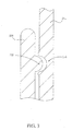
- Fig. 3 is a cross-section view of a fixing unit 230 of the clothes hanger 200 in Fig. 2 .
- the clothes hanger 200 comprises a hanging rod 210 and a linkage mechanism 220.
- the hanging rod 210 comprises a hanging unit 212 and a guiding rod 214.
- the hanging unit 212 is a hook for hanging the clothes hanger 200 on a clothes-drying rope or a clothes drying pole; however, the hanging unit 212 can also be a hanging strip or other design with similar function.
- An upper end of the guiding rod 214 is connected to the hanging unit 212.
- the guiding rod 214 can be a straight pole or other similar object.
- the linkage mechanism 220 comprises a sliding unit 270, a first linkage arm 272, and a second linkage arm 274.
- the sliding unit 270 is affixed in an up-down slidable manner to the guiding rod 214.
- the first linkage arm 272 is installed at a left side of the guiding rod 214
- the second linkage arm 274 is installed at a right side of the guiding rod 214.
- Both the first linkage arm 272 and the second linkage arm 274 comprise a sub-upper arm 222 and a sub-lower arm 224.
- First ends 222a of the sub-upper arms 222 (also first ends of the first and second linkage arms 272, 274) are connected to the sliding unit 270.
- Second ends 224b of the sub-upper arms 222 are connected to first ends 224a of the sub-lower arms 224.
- second ends 224b of the sub-lower arms 224 (and second ends of the first and second linkage arms 272, 274) are connected to a lower end of the guiding rod 214.
- the sliding unit 270, the sub-upper arms 222, and the sub-lower arms can be connected to each other by hinges or other similar knuckle mechanisms.
- the linkage mechanism 220 is monolithic, and folding areas between the sliding unit 270, the sub-upper arms 222, and the sub-lower arms 224 are thinned out, such that the number of molds for injection molding can be reduced.
- the clothes hanger 200 further comprises a fixing unit 230 for fixing the sliding unit 270 at a specific position of the guiding rod 214.
- the fixing unit 230 has a bump 232
- the guiding rod 214 has a corresponding recess 216.
- the fixing unit 230 shown in Fig. 3 is just one of embodiments of the present invention.
- the fixing unit 230 can be other kinds of designs; for example, the fixing unit 230 can also use friction, magnetic force, gravity, etc. to fix the sliding unit 270.
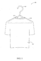
- Fig. 4 is an illustration of clothes 240 before being hung on the clothes hanger 200 in Fig. 2 .
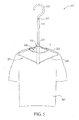
- Fig. 5 is an illustration of the clothes 240 after being hung by the clothes hanger 200 in Fig. 2 .
- the sliding unit 270 is at a first position A, the folding areas between the sub-upper arms 222 and the sub-lower arms 224 are close to the guiding rod 214, according to the design of the linkage mechanism 220. Therefore, the wingspan of the linkage mechanism 220 is smaller than the opening of neckline 242, and the clothes hanger 200 is not able to hang the clothes 240.
- the linkage mechanism 220 is in a closed-state then.
- the fixing unit 230 is capable of fixing the sliding unit 270 at the first position A or the second position B; that is, to keep the linkage mechanism 220 in a closed-state or an open-state.
- the clothes hanger 200 of the present invention is more convenient than the conventional clothes hanger 100 when hanging and unhanging clothes.
- the user can put the linkage mechanism 220 in a closed-state through the opening of neckline 242, and then pull the sliding unit 270 downward, thus causing the wingspan of the linkage mechanism 220 to increase as the sliding unit 270 is moved downward till the wingspan of the linkage mechanism 220 is large enough to hang the clothes 240.
- the user when trying to remove the clothes 240 from the clothes hanger 200, the user can move the sliding unit 270 upward, thus causing the wingspan of the linkage mechanism 220 to decrease as the sliding unit 270 is moved upward till the wingspan of the linkage mechanism 220 is small enough to allow removal of the clothes 240.
- the user needs only to move the sliding unit 270 when hanging and unhanging clothes.
- the clothes hanger 200 of the present invention will not stretch the neckline 242 when being inserted into or removed from the clothes; therefore, the clothes will not be damaged or deformed at the neckline area anymore.
- Fig. 7 is an illustration of another clothes hanger 700 of the present invention in the closed-state.
- Fig. 8 is an illustration of the clothes hanger 700 in Fig. 7 in the open-state.
- the clothes hanger 700 comprises a hanging rod 710 and a linkage mechanism 720. Similar to the hanging rod 210 in Fig. 2 , the hanging rod 710 also comprises a hanging unit 712 and a guiding rod 714. Therefore, the hanging rod 710 is not further described. Different from the clothes hanger 200 in Fig. 2 , there is no folding area at the middle of a first linkage arm 772 and a second linkage arm 774 of the linkage mechanism 720.
- first linkage arm 772 and the second linkage arm 774 are made of elastic material.
- the sliding unit 770 is affixed in an up-down slidable manner to the guiding rod 714.
- the first linkage arm 772 is installed at a left side of the guiding rod 714
- the second linkage arm 774 is installed at a right side of the guiding rod 714.
- First ends 772a, 774a of the first and second linkage arms 772, 774 are connected to the sliding unit 770
- second ends 772b, 774b of the first and second linkage arms 772, 774 are connected to a lower end of the guiding rod 714.
- the sliding unit 770 When the sliding unit 770 is free without being forced, the sliding unit 770 is at a third position C, and the middle areas of the first linkage arm 772 and the second linkage arm 774 are close to the guiding rod 714.
- the linkage mechanism 720 is in a closed-state then.
- the sliding unit 270 When the sliding unit 270 is forced to move downward from the third position C, the first linkage arm 772 and the second linkage arm 774 are bent gradually, and the middle areas of the first linkage arm 772 and the second linkage arm 774 move outward.
- the sliding unit 270 arrives at a fourth position D and is fixed by the fixing unit 730, the wingspan of the linkage mechanism 720 is large enough to hang the clothes 740.
- the linkage mechanism 720 is in an open-state then.
- the sliding unit 770 when the sliding unit 770 is released by the fixing unit 730 from the fourth position D, the sliding unit 770 will be pushed back to the third position C by the first linkage arm 772 and the second linkage arm 774, and the linkage mechanism 720 automatically goes to the closed-state to allow removal of the clothes 740.
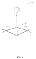
- Fig. 9 is an illustration of the clothes hanger 200 in Fig. 2 further comprising extension units 260.
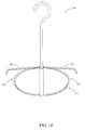
- Fig. 10 is an illustration of the clothes hanger 700 in Fig. 7 further comprising extension units 760.
- the clothes hangers 200, 700 further comprise extension units 260, 760 installed on the linkage mechanisms 220, 720.
- the extension units 260, 760 will extend out of the first linkage arm 272, 772 and the second linkage arm 274, 774 to increase the wingspan of the linkage mechanisms 220, 720.
- Adding the extension units 260, 760 can also reduce the required length of the first linkage arms 272, 772 and the second linkage arms 274, 774 to save space further.
- the retractable clothes hangers 200, 700 of the present invention can easily hang and unhang clothes by moving the sliding units 270, 770. Also, the necklines of the clothes will not be stretched and thus damaged. In addition, the user can use just one hand to move the sliding units 270, 770 for hanging and unhanging the clothes; thus the retractable clothes hangers 200, 700 of the present invention provide more convenience.
Landscapes
- Holders For Apparel And Elements Relating To Apparel (AREA)
Abstract
This invention relates to a clothes hanger comprising a hanging rod and a linkage mechanism. The hanging rod comprises a hanging unit and a guiding rod with its upper end connected to the hanging unit. The linkage mechanism comprises a sliding unit, a first linkage arm, and a second linkage arm. The sliding unit is affixed in an up-down slidable manner to the guiding rod. The first linkage arm is installed at a left side of the guiding rod, and the first linkage arm has a first end connected to the sliding unit and a second end connected to a lower end of the guiding rod. The second linkage arm is installed at a right side of the guiding rod, and the second linkage arm has a first end connected to the sliding unit and a second end connected to the lower end of the guiding rod.
Description
- The present invention relates to a clothes hanger, and more particularly, to a retractable clothes hanger.
- Please refer to
Fig. 1. Fig. 1 is an illustration of aconventional clothes hanger 100holding clothes 110. Theclothes hanger 100 comprises ahook 102 and a hangingframe 104. Theclothes hanger 100 can be hung on a clothes-drying rope or a clothes drying pole by thehook 102. The hangingframe 104 is connected to thehook 102 for hanging clothes. - However, the wingspan of the hanging
frame 104 of theconventional clothes hanger 100 is much bigger than the opening ofneckline 112 of theclothes 110 in order to prevent theclothes 110 from falling off. When the user is trying to hang theclothes 110, theneckline 112 of theclothes 110 needs to be stretched wide enough for the hangingframe 104 to be inserted into theclothes 110. Similarly, when the user is trying to remove theclothes 110 from the hangingframe 104, theneckline 112 of theclothes 110 needs to be stretched again in order to remove the hangingframe 104 from theclothes 110. - To insert the
conventional clothes hanger 100 into theclothes 110, the user needs to stretch theneckline 112 of theclothes 110 with both hands, which causes some inconvenience in use. In addition, the neckline of theclothes 110 will be loosened and deformed by the frequent stretching. - It is therefore an objective of the present invention to provide a retractable clothes hanger in order to solve the problems of the prior art.
- The clothes hanger of the present invention comprises a hanging rod and a linkage mechanism. The hanging rod comprises a hanging unit and a guiding rod with its upper end connected to the hanging unit. The linkage mechanism comprises a sliding unit, a first linkage arm, and a second linkage arm. The sliding unit is affixed to the guiding rod in an up-down slidable manner. The first linkage arm is installed at a left side of the guiding rod, and the first linkage arm has a first end connected to the sliding unit and a second end connected to a lower end of the guiding rod. The second linkage arm is installed at a right side of the guiding rod, and the second linkage arm has a first end connected to the sliding unit and a second end connected to the lower end of the guiding rod. When the sliding unit is moved to a first position corresponding to the guiding rod, the linkage mechanism is in a closed-state, and when the sliding unit is moved to a second position corresponding to the guiding rod, the linkage mechanism is in an open-state for hanging clothes.
- Other objects, advantages, and novel features of the present invention will become more apparent from the following detailed description when taken in conjunction with the accompanying drawings.
- These and other objects and advantages of the present invention will become apparent from the following description of the accompanying drawings, which disclose several embodiments of the present invention. It is to be understood that the drawings are to be used for purposes of illustration only, and not as a definition of the invention.
- In the drawings, wherein similar reference numerals denote similar elements throughout the several views:
-
Fig. 1 is an illustration of a conventional clothes hanger hanging clothes. -
Fig. 2 is an illustration of a retractable clothes hanger of the present invention. -
Fig. 3 is a cross-section view of a fixing unit of the clothes hanger inFig. 2 . -
Fig. 4 is an illustration of clothes before being hung by the clothes hanger inFig. 2 . -
Fig. 5 is an illustration of the clothes after being hung by the clothes hanger inFig. 2 . -
Fig. 6 is an illustration of the clothes hanger inFig. 2 further comprising a spring. -
Fig. 7 is an illustration of another clothes hanger of the present invention in the closed-state. -
Fig. 8 is an illustration of the clothes hanger inFig. 7 in the open-state. -
Fig. 9 is an illustration of the clothes hanger inFig. 2 further comprising extension units. -
Fig. 10 is an illustration of the clothes hanger inFig. 7 further comprising extension units. - Please refer to
Fig. 2 andFig. 3 .Fig. 2 is an illustration of aretractable clothes hanger 200 of the present invention.Fig. 3 is a cross-section view of afixing unit 230 of theclothes hanger 200 inFig. 2 . Theclothes hanger 200 comprises ahanging rod 210 and alinkage mechanism 220. Thehanging rod 210 comprises ahanging unit 212 and a guidingrod 214. In the embodiment ofFig. 2 , thehanging unit 212 is a hook for hanging theclothes hanger 200 on a clothes-drying rope or a clothes drying pole; however, thehanging unit 212 can also be a hanging strip or other design with similar function. An upper end of the guidingrod 214 is connected to the hangingunit 212. The guidingrod 214 can be a straight pole or other similar object. Thelinkage mechanism 220 comprises asliding unit 270, afirst linkage arm 272, and asecond linkage arm 274. Thesliding unit 270 is affixed in an up-down slidable manner to the guidingrod 214. Thefirst linkage arm 272 is installed at a left side of theguiding rod 214, and thesecond linkage arm 274 is installed at a right side of the guidingrod 214. Both thefirst linkage arm 272 and thesecond linkage arm 274 comprise asub-upper arm 222 and asub-lower arm 224. Firstends 222a of the sub-upper arms 222 (also first ends of the first andsecond linkage arms 272, 274) are connected to thesliding unit 270.Second ends 224b of thesub-upper arms 222 are connected tofirst ends 224a of thesub-lower arms 224. Also,second ends 224b of the sub-lower arms 224 (and second ends of the first andsecond linkage arms 272, 274) are connected to a lower end of the guidingrod 214. Thesliding unit 270, thesub-upper arms 222, and the sub-lower arms can be connected to each other by hinges or other similar knuckle mechanisms. However, in the present embodiment, thelinkage mechanism 220 is monolithic, and folding areas between thesliding unit 270, thesub-upper arms 222, and thesub-lower arms 224 are thinned out, such that the number of molds for injection molding can be reduced. - In addition, the
clothes hanger 200 further comprises afixing unit 230 for fixing the slidingunit 270 at a specific position of the guidingrod 214. As shown inFig. 3 , thefixing unit 230 has abump 232, and theguiding rod 214 has acorresponding recess 216. When thebump 232 of thefixing unit 230 is moved and stuck in therecess 216 of theguiding rod 214, thesliding unit 270 will be fixed on the guidingrod 214 until thesliding unit 270 is forced again to move thebump 232 of thefixing unit 230 out of therecess 216 of theguiding rod 214. However, thefixing unit 230 shown inFig. 3 is just one of embodiments of the present invention. Thefixing unit 230 can be other kinds of designs; for example, thefixing unit 230 can also use friction, magnetic force, gravity, etc. to fix the slidingunit 270. - Please refer to
Fig. 4 andFig. 5 , and refer toFig. 2 andFig. 3 as well.Fig. 4 is an illustration ofclothes 240 before being hung on theclothes hanger 200 inFig. 2 .Fig. 5 is an illustration of theclothes 240 after being hung by theclothes hanger 200 inFig. 2 . When the slidingunit 270 is at a first position A, the folding areas between thesub-upper arms 222 and thesub-lower arms 224 are close to the guidingrod 214, according to the design of thelinkage mechanism 220. Therefore, the wingspan of thelinkage mechanism 220 is smaller than the opening ofneckline 242, and theclothes hanger 200 is not able to hang theclothes 240. Thelinkage mechanism 220 is in a closed-state then. When the slidingunit 270 is moved downward from the first position A, the folding areas between thesub-upper arms 222 and thesub-lower arms 224 gradually move outward according to the design of thelinkage mechanism 220. When the slidingunit 270 arrives at a second position B, the folding areas between thesub-upper arms 222 and thesub-lower arms 224 are apart from the guidingrod 214; therefore, the wingspan of thelinkage mechanism 220 is large enough to hang theclothes 240. Thelinkage mechanism 220 is in an open-state then. In the present embodiment, the fixingunit 230 is capable of fixing the slidingunit 270 at the first position A or the second position B; that is, to keep thelinkage mechanism 220 in a closed-state or an open-state. - As shown in
Fig. 4 andFig. 5 , theclothes hanger 200 of the present invention is more convenient than theconventional clothes hanger 100 when hanging and unhanging clothes. For example, when trying to hang theclothes 240 on theclothes hanger 200, the user can put thelinkage mechanism 220 in a closed-state through the opening ofneckline 242, and then pull the slidingunit 270 downward, thus causing the wingspan of thelinkage mechanism 220 to increase as the slidingunit 270 is moved downward till the wingspan of thelinkage mechanism 220 is large enough to hang theclothes 240. Correspondingly, when trying to remove theclothes 240 from theclothes hanger 200, the user can move the slidingunit 270 upward, thus causing the wingspan of thelinkage mechanism 220 to decrease as the slidingunit 270 is moved upward till the wingspan of thelinkage mechanism 220 is small enough to allow removal of theclothes 240. The user needs only to move the slidingunit 270 when hanging and unhanging clothes. Moreover, theclothes hanger 200 of the present invention will not stretch theneckline 242 when being inserted into or removed from the clothes; therefore, the clothes will not be damaged or deformed at the neckline area anymore. - In addition, the
clothes hanger 200 can further comprise a spring to move the slidingunit 270 for more convenience. As shown inFig. 6 , aspring 250 is installed at the folding area between thesub-upper arms 222 and thesub-lower arms 224. Thespring 250 can provide force to move the slidingunit 270 to the first position A (or the second position B), such that thelinkage mechanism 220 can automatically go to the closed-state (or the open-state) when the fixingunit 230 releases the slidingunit 270. - Please refer to
Fig. 7 andFig. 8 .Fig. 7 is an illustration of anotherclothes hanger 700 of the present invention in the closed-state.Fig. 8 is an illustration of theclothes hanger 700 inFig. 7 in the open-state. Theclothes hanger 700 comprises a hangingrod 710 and alinkage mechanism 720. Similar to the hangingrod 210 inFig. 2 , the hangingrod 710 also comprises a hangingunit 712 and a guidingrod 714. Therefore, the hangingrod 710 is not further described. Different from theclothes hanger 200 inFig. 2 , there is no folding area at the middle of afirst linkage arm 772 and asecond linkage arm 774 of thelinkage mechanism 720. Also, thefirst linkage arm 772 and thesecond linkage arm 774 are made of elastic material. The slidingunit 770 is affixed in an up-down slidable manner to the guidingrod 714. Thefirst linkage arm 772 is installed at a left side of the guidingrod 714, and thesecond linkage arm 774 is installed at a right side of the guidingrod 714. First ends 772a, 774a of the first andsecond linkage arms unit 770, and second ends 772b, 774b of the first andsecond linkage arms rod 714. When the slidingunit 770 is free without being forced, the slidingunit 770 is at a third position C, and the middle areas of thefirst linkage arm 772 and thesecond linkage arm 774 are close to the guidingrod 714. Thelinkage mechanism 720 is in a closed-state then. When the slidingunit 270 is forced to move downward from the third position C, thefirst linkage arm 772 and thesecond linkage arm 774 are bent gradually, and the middle areas of thefirst linkage arm 772 and thesecond linkage arm 774 move outward. When the slidingunit 270 arrives at a fourth position D and is fixed by the fixingunit 730, the wingspan of thelinkage mechanism 720 is large enough to hang theclothes 740. Thelinkage mechanism 720 is in an open-state then. In addition, when the slidingunit 770 is released by the fixingunit 730 from the fourth position D, the slidingunit 770 will be pushed back to the third position C by thefirst linkage arm 772 and thesecond linkage arm 774, and thelinkage mechanism 720 automatically goes to the closed-state to allow removal of theclothes 740. - Please refer to
Fig. 9 andFig. 10 .Fig. 9 is an illustration of theclothes hanger 200 inFig. 2 further comprisingextension units 260.Fig. 10 is an illustration of theclothes hanger 700 inFig. 7 further comprisingextension units 760. As shown inFig. 9 andFig. 10 , theclothes hangers extension units linkage mechanisms clothes hangers extension units first linkage arm second linkage arm linkage mechanisms extension units first linkage arms second linkage arms - In contrast to the prior art, the
retractable clothes hangers units units retractable clothes hangers - Although the present invention has been explained in relation to its preferred embodiments, it is to be understood that many other possible modifications and variations can be made without departing from the spirit and scope of the invention as hereinafter claimed.
Claims (10)
- A retractable clothes hanger comprising:a hanging rod comprising:a hanging unit; anda guiding rod with its upper end connected to the hanging unit; anda linkage mechanism comprising:wherein when the sliding unit is moved to a first position corresponding to the guiding rod, the linkage mechanism is in a closed-state, and when the sliding unit is moved to a second position corresponding to the guiding rod, the linkage mechanism is in an open-state for hanging clothes.a sliding unit affixed in an up-down slidable manner to the guiding rod;a first linkage arm installed at a left side of the guiding rod, the first linkage arm having a first end connected to the sliding unit and a second end connected to a lower end of the guiding rod; anda second linkage arm installed at a right side of the guiding rod, the second linkage arm having a first end connected to the sliding unit and a second end connected to the lower end of the guiding rod;
- The retractable clothes hanger as claimed in claim 1 further comprising a fixing unit for fixing the sliding unit at a specific position of the guiding rod.
- The retractable clothes hanger as claimed in claim 2, wherein the specific position is the first position.
- The retractable clothes hanger as claimed in claim 2, wherein the specific position is the second position.
- The retractable clothes hanger as claimed in claim 1 further comprising an extension unit installed on the linkage mechanism for increasing the wingspan of the linkage mechanism in the open-state.
- The retractable clothes hanger as claimed in claim 1, wherein both the first linkage arm and the second linkage arm comprise:a sub-upper arm having a first end and a second end, the first end of the sub-upper arm connected to the sliding unit; anda sub-lower arm having a first end and a second end, the first end of the sub-lower arm connected to the second end of the sub-upper arm, the second end of the sub-lower arm connected to the lower end of the guiding rod.
- The retractable clothes hanger as claimed in claim 6, wherein the linkage mechanism is monolithic, and folding areas between the sliding unit, the sub-upper arms, and the sub-lower arms are thinned out.
- The retractable clothes hanger as claimed in claim 1 further comprising a spring for moving the sliding unit.
- The retractable clothes hanger as claimed in claim 1, wherein the first linkage arm and the second linkage arm are made of elastic material.
- The retractable clothes hanger as claimed in claim 1, wherein the hanging unit is a hook.
Applications Claiming Priority (1)
| Application Number | Priority Date | Filing Date | Title |
|---|---|---|---|
| TW096213032U TWM332441U (en) | 2007-08-08 | 2007-08-08 | Retractable clothes hanger |
Publications (1)
| Publication Number | Publication Date |
|---|---|
| EP2022378A1 true EP2022378A1 (en) | 2009-02-11 |
Family
ID=39739476
Family Applications (1)
| Application Number | Title | Priority Date | Filing Date |
|---|---|---|---|
| EP08161725A Withdrawn EP2022378A1 (en) | 2007-08-08 | 2008-08-04 | Retractable clothes hanger |
Country Status (4)
| Country | Link |
|---|---|
| US (1) | US7743954B2 (en) |
| EP (1) | EP2022378A1 (en) |
| JP (1) | JP3145493U (en) |
| TW (1) | TWM332441U (en) |
Cited By (5)
| Publication number | Priority date | Publication date | Assignee | Title |
|---|---|---|---|---|
| CN102599789A (en) * | 2012-03-18 | 2012-07-25 | 杨加旭 | Illuminating device of clothing hanging rod |
| CN102871508A (en) * | 2012-10-18 | 2013-01-16 | 夏婷 | Portable type foldable and telescopic hanger |
| CN104783627A (en) * | 2015-03-26 | 2015-07-22 | 唐海玲 | Novel clothes hanger |
| CN105795855A (en) * | 2016-03-23 | 2016-07-27 | 孔国琴 | Telescopic clothes hanger |
| AT523934A4 (en) * | 2020-12-02 | 2022-01-15 | Gurdet Agata | laundry rack |
Families Citing this family (10)
| Publication number | Priority date | Publication date | Assignee | Title |
|---|---|---|---|---|
| US8770452B1 (en) | 2011-09-28 | 2014-07-08 | Steven T. Gottlieb | Expandable clothes hanger |
| US9468326B2 (en) | 2014-07-23 | 2016-10-18 | C&A Business World, Llc | Collapsible hanger apparatus and methods of use thereof |
| WO2017197256A1 (en) | 2016-05-12 | 2017-11-16 | Kyle Baltz | Single hand operated collapsing hanger |
| JP7117721B2 (en) * | 2017-09-07 | 2022-08-15 | 瀬倉株式会社 | Hanger |
| DE102017220174A1 (en) * | 2017-11-13 | 2019-05-16 | Brose Fahrzeugteile Gmbh & Co. Kg, Coburg | Adjustable hanger assembly |
| US10856684B2 (en) * | 2018-06-05 | 2020-12-08 | Susana Mauri | Collapsible hanger |
| TWI683937B (en) * | 2019-04-18 | 2020-02-01 | 國立勤益科技大學 | The hanger structure improvement |
| CN109953603B (en) * | 2019-05-07 | 2024-03-15 | 浙江恒申科技股份有限公司 | Folding clothes hanger |
| US11412874B1 (en) * | 2020-03-09 | 2022-08-16 | Kwame Dwomoh | Spring biased clothes hanger |
| CN113229696B (en) * | 2021-05-13 | 2022-07-12 | 王立珍 | Clothes hanger convenient to receive and release |
Citations (6)
| Publication number | Priority date | Publication date | Assignee | Title |
|---|---|---|---|---|
| US958366A (en) * | 1909-10-30 | 1910-05-17 | Edgar C Clausen | Garment-hanger. |
| US1111147A (en) * | 1913-04-24 | 1914-09-22 | Oscar Fogde | Garment-hanger. |
| US1886869A (en) * | 1931-03-19 | 1932-11-08 | Bland B Button | Collapsible garment hanger |
| GB640774A (en) * | 1948-08-20 | 1950-07-26 | Alfred Henry Mallinson | New or improved folding device for stretching and suspending trousers |
| US4227632A (en) * | 1978-06-08 | 1980-10-14 | Collis John H | Flexible garment hanger |
| FR2593693A1 (en) * | 1986-02-04 | 1987-08-07 | Letard Michel | Folding coat-hanger |
Family Cites Families (4)
| Publication number | Priority date | Publication date | Assignee | Title |
|---|---|---|---|---|
| US2290722A (en) * | 1940-02-19 | 1942-07-21 | Weingarten Murray | Collapsible garment hanger |
| US2654484A (en) * | 1950-08-10 | 1953-10-06 | Win Bernhard | Foldable hanger |
| US2754038A (en) * | 1954-02-05 | 1956-07-10 | Thomas L Varker | Garment hanger |
| JPH09294667A (en) * | 1996-03-06 | 1997-11-18 | N K G:Kk | Hanger |
-
2007
- 2007-08-08 TW TW096213032U patent/TWM332441U/en unknown
-
2008
- 2008-07-03 US US12/167,424 patent/US7743954B2/en not_active Expired - Fee Related
- 2008-07-29 JP JP2008005216U patent/JP3145493U/en not_active Expired - Fee Related
- 2008-08-04 EP EP08161725A patent/EP2022378A1/en not_active Withdrawn
Patent Citations (6)
| Publication number | Priority date | Publication date | Assignee | Title |
|---|---|---|---|---|
| US958366A (en) * | 1909-10-30 | 1910-05-17 | Edgar C Clausen | Garment-hanger. |
| US1111147A (en) * | 1913-04-24 | 1914-09-22 | Oscar Fogde | Garment-hanger. |
| US1886869A (en) * | 1931-03-19 | 1932-11-08 | Bland B Button | Collapsible garment hanger |
| GB640774A (en) * | 1948-08-20 | 1950-07-26 | Alfred Henry Mallinson | New or improved folding device for stretching and suspending trousers |
| US4227632A (en) * | 1978-06-08 | 1980-10-14 | Collis John H | Flexible garment hanger |
| FR2593693A1 (en) * | 1986-02-04 | 1987-08-07 | Letard Michel | Folding coat-hanger |
Cited By (7)
| Publication number | Priority date | Publication date | Assignee | Title |
|---|---|---|---|---|
| CN102599789A (en) * | 2012-03-18 | 2012-07-25 | 杨加旭 | Illuminating device of clothing hanging rod |
| CN102871508A (en) * | 2012-10-18 | 2013-01-16 | 夏婷 | Portable type foldable and telescopic hanger |
| CN104783627A (en) * | 2015-03-26 | 2015-07-22 | 唐海玲 | Novel clothes hanger |
| CN105795855A (en) * | 2016-03-23 | 2016-07-27 | 孔国琴 | Telescopic clothes hanger |
| AT523934A4 (en) * | 2020-12-02 | 2022-01-15 | Gurdet Agata | laundry rack |
| AT523934B1 (en) * | 2020-12-02 | 2022-01-15 | Gurdet Agata | laundry rack |
| WO2022115892A1 (en) * | 2020-12-02 | 2022-06-09 | Gurdet Agata | Clothes holder |
Also Published As
| Publication number | Publication date |
|---|---|
| TWM332441U (en) | 2008-05-21 |
| US7743954B2 (en) | 2010-06-29 |
| US20090039116A1 (en) | 2009-02-12 |
| JP3145493U (en) | 2008-10-09 |
Similar Documents
| Publication | Publication Date | Title |
|---|---|---|
| US7743954B2 (en) | Retractable clothes hanger | |
| CN207168337U (en) | Hanging hook | |
| CN108277620B (en) | Anti-blowing clothes hanger | |
| US20210010192A1 (en) | Hanger for preventing the reverse flow of cloths with adjustable hanging pressure and hanging device for preventing the reverse flow of cloths which uses the same | |
| JP6554050B2 (en) | Pinch unit and holding method of object to be held | |
| CN203762810U (en) | Folding clothes hanger | |
| CN203360879U (en) | Self-locking clothes airing hook | |
| CN207721626U (en) | Wind-proof clothes hanger | |
| CN201189063Y (en) | Telescopic clothes rack | |
| CN201499972U (en) | Anti-skid clothes rack | |
| CN104832015B (en) | Support rocker for hanging window and hanging window | |
| CN208692874U (en) | Multifunctional clothes rack accepting rack | |
| KR20150011949A (en) | use elastic force one butten hanger | |
| JP3899358B2 (en) | Opening and closing hanger | |
| CN215077382U (en) | Combined plastic clothes hanger | |
| CN221577437U (en) | Adjustable clothes hanger | |
| CN201139386Y (en) | Telescopic clothes rack | |
| JP4018710B2 (en) | Arm movable hanger | |
| CN216316988U (en) | Clothes hanger with clamp | |
| JP3138843U (en) | Laundry dryer | |
| US20250241462A1 (en) | Systems for Hanging Articles Relative to Surface | |
| CN204541641U (en) | A kind of Anti-fall dries in the air garment support bar | |
| JP3089676U (en) | Hanger equipment | |
| CN206122383U (en) | Clamping device for wire drawing machine | |
| KR20230115672A (en) | Clothes hanger with fixing function |
Legal Events
| Date | Code | Title | Description |
|---|---|---|---|
| PUAI | Public reference made under article 153(3) epc to a published international application that has entered the european phase |
Free format text: ORIGINAL CODE: 0009012 |
|
| AK | Designated contracting states |
Kind code of ref document: A1 Designated state(s): AT BE BG CH CY CZ DE DK EE ES FI FR GB GR HR HU IE IS IT LI LT LU LV MC MT NL NO PL PT RO SE SI SK TR |
|
| AX | Request for extension of the european patent |
Extension state: AL BA MK RS |
|
| AKX | Designation fees paid | ||
| STAA | Information on the status of an ep patent application or granted ep patent |
Free format text: STATUS: THE APPLICATION IS DEEMED TO BE WITHDRAWN |
|
| 18D | Application deemed to be withdrawn |
Effective date: 20090812 |
|
| REG | Reference to a national code |
Ref country code: DE Ref legal event code: 8566 |