EP2023840B1 - Dynamometrisches werkzeug zur medizinischen verwendung - Google Patents
Dynamometrisches werkzeug zur medizinischen verwendung Download PDFInfo
- Publication number
- EP2023840B1 EP2023840B1 EP07729349A EP07729349A EP2023840B1 EP 2023840 B1 EP2023840 B1 EP 2023840B1 EP 07729349 A EP07729349 A EP 07729349A EP 07729349 A EP07729349 A EP 07729349A EP 2023840 B1 EP2023840 B1 EP 2023840B1
- Authority
- EP
- European Patent Office
- Prior art keywords
- spring member
- shaft
- tool according
- strips
- gripping body
- Prior art date
- Legal status (The legal status is an assumption and is not a legal conclusion. Google has not performed a legal analysis and makes no representation as to the accuracy of the status listed.)
- Not-in-force
Links
Images


Classifications
-
- A—HUMAN NECESSITIES
- A61—MEDICAL OR VETERINARY SCIENCE; HYGIENE
- A61B—DIAGNOSIS; SURGERY; IDENTIFICATION
- A61B17/00—Surgical instruments, devices or methods
- A61B17/56—Surgical instruments or methods for treatment of bones or joints; Devices specially adapted therefor
- A61B17/58—Surgical instruments or methods for treatment of bones or joints; Devices specially adapted therefor for osteosynthesis, e.g. bone plates, screws or setting implements
- A61B17/88—Osteosynthesis instruments; Methods or means for implanting or extracting internal or external fixation devices
- A61B17/8875—Screwdrivers, spanners or wrenches
-
- A—HUMAN NECESSITIES
- A61—MEDICAL OR VETERINARY SCIENCE; HYGIENE
- A61C—DENTISTRY; APPARATUS OR METHODS FOR ORAL OR DENTAL HYGIENE
- A61C8/00—Means to be fixed to the jaw-bone for consolidating natural teeth or for fixing dental prostheses thereon; Dental implants; Implanting tools
- A61C8/0089—Implanting tools or instruments
-
- B—PERFORMING OPERATIONS; TRANSPORTING
- B25—HAND TOOLS; PORTABLE POWER-DRIVEN TOOLS; MANIPULATORS
- B25B—TOOLS OR BENCH DEVICES NOT OTHERWISE PROVIDED FOR, FOR FASTENING, CONNECTING, DISENGAGING OR HOLDING
- B25B23/00—Details of, or accessories for, spanners, wrenches, screwdrivers
- B25B23/14—Arrangement of torque limiters or torque indicators in wrenches or screwdrivers
- B25B23/142—Arrangement of torque limiters or torque indicators in wrenches or screwdrivers specially adapted for hand operated wrenches or screwdrivers
-
- A—HUMAN NECESSITIES
- A61—MEDICAL OR VETERINARY SCIENCE; HYGIENE
- A61B—DIAGNOSIS; SURGERY; IDENTIFICATION
- A61B90/00—Instruments, implements or accessories specially adapted for surgery or diagnosis and not covered by any of the groups A61B1/00 - A61B50/00, e.g. for luxation treatment or for protecting wound edges
- A61B90/03—Automatic limiting or abutting means, e.g. for safety
- A61B2090/031—Automatic limiting or abutting means, e.g. for safety torque limiting
-
- A—HUMAN NECESSITIES
- A61—MEDICAL OR VETERINARY SCIENCE; HYGIENE
- A61C—DENTISTRY; APPARATUS OR METHODS FOR ORAL OR DENTAL HYGIENE
- A61C1/00—Dental machines for boring or cutting ; General features of dental machines or apparatus, e.g. hand-piece design
- A61C1/08—Machine parts specially adapted for dentistry
- A61C1/18—Flexible shafts; Clutches or the like; Bearings or lubricating arrangements; Drives or transmissions
- A61C1/185—Drives or transmissions
- A61C1/186—Drives or transmissions with torque adjusting or limiting means
Definitions
- the present invention relates to the field of tools for medical use. More particularly, it relates to a dynamometric tool for tightening and loosening screws or various objects having a thread, during a surgical procedure.
- the instrument holder is extended by a pivoting shaft in the gripping body. It is frictionally connected to the gripping body by means of a spring member disposed between the shaft and the gripping body. Friction is provided by two Breguet toothing, that is to say saw-shaped edge teeth, one being secured to the instrument holder and the other being rotatably connected to the gripping body. Springs press the two Breguet toothings against each other so as to rotate the instrument holder and the gripping body. When the tightening torque is greater than the friction imposed between the two Breguet teeth by the springs, the latter rub against each other and escape. The instrument holder is then no longer rotated by the gripping body. The applicable maximum tightening torque can be adjusted by modulating the pressure exerted by the springs.
- the friction created between the teeth is particularly important and it is necessary, in order to obtain an acceptable accuracy and durability of the tool, that the Breguet teeth be metallic. They, as well as the springs, are made of a stainless steel, allowing a surgical use as hygienic as possible. However, it is necessary to grease the metal parts in friction, which is not very satisfactory from a sanitary point of view, since there is a risk of grease pouring on the outside of the tool during sterilization operations. . In addition, the accuracy of such a tool is unsatisfactory (+/- 10%) and it is necessary to perform regular calibrations.
- the present invention therefore aims to provide a torque tool free from the aforementioned drawbacks and which, in particular, is precise, lightweight, easy to handle. Especially, when the maximum tightening torque is reached, no stray shake is felt by the user. Disclosure of the invention
- the instrument holder is frictionally connected to the gripping body by means of a spring member disposed between the shaft and the gripping body.
- the spring member comprises a plurality of elastically deformable lamellae in a substantially radial direction.
- the spring member comprises a plurality of lamellae arranged mainly in non-radial directions.
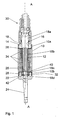
- the figure 1 shows a gripping body 10, of longitudinal axis AA. Along this axis, the body 10 is traversed by a cylindrical channel 12. A first end of the gripping body is provided with a screw thread 10a to cooperate with a first plug 14. The latter comprises a hole 16 for passing a tree 18 which will be described in more detail below.
- the second end of the gripping body is also provided with a screw thread 10b to cooperate with a second plug 22.
- a rod 24 which can be connected to a device not shown, equipped with a motor to put the rod in rotation.
- a handle may be fixed around the rod 24 to extend the grip body 10 and facilitate handling of the tool.
- the walls of the second cap 22 form a housing 26 whose bottom has a cylindrical orifice 28 intended to receive the end of the shaft 18.
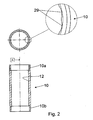
- the figure 2 illustrates in detail an embodiment of the structure of the channel 12 whose inner wall has a succession of recesses 29, typically of cylindrical general shape, oriented along the axis AA.
- the recesses 19 occupy the entire length of the channel between the two threads 10a and 10b.
- the portion of the instrument holder connecting the instrument is not part of the invention and will not be described in detail.
- the instrument holder 30 is extended by the aforementioned shaft 18. It is dimensioned so as to pass through the hole 16, take place in the channel 12 of the gripping body 10, while its free end takes place in the housing 26 and in the orifice 28. More specifically, the shaft 18 comprises a first portion 18a adjusted to the dimension of the hole 16. Then, moving away from the part of the instrument holder intended to receive an instrument, a second portion 18b intended to be housed in the channel 12. The second portion 18b is structured so as to have a section typically star, and thus forms a male member can be rotatably connected with a female member of corresponding shape. Finally, the shaft ends with a third portion 18c intended to take place in the housing 26 and a fourth portion 18d adjusted to the dimensions of the orifice 28. The latter two portions are separated by an annular groove 32 orthogonal to the longitudinal axis of the tree.
- the instrument holder 30 is intended to be pivotally mounted, frictionally, in the channel 12. According to an important aspect of the invention, the friction is ensured by at least one spring member 34, an example of which is illustrated in FIG. figure 3 .
- This spring member 34 is generally cylindrical in shape and comprises, in its center, an opening 35 structured so as to have a section typically in a star shape, and thus forms a female member shaped to be mounted without play and integral in rotation on the portion 18b
- the star shape proposed is only one example, other types of slots, structures or pins can be used, the essential is that these elements are integral in rotation.
- the spring member 34 comprises a plurality of strips 36 which are elastically deformable in a substantially radial direction. These strips 36 are oriented outwards, mainly in non-radial directions and terminate, in a preferred embodiment, by a cylindrical portion 36a substantially orthogonal to the general plane of the spring member.
- the spring member 34 is intended to be mounted on the shaft 18, interposed between the latter and the wall of the channel 12.
- the cylindrical portions 36a are thus defined so as to cooperate with the recesses 29 of the channel.
- Other shapes can be chosen as long as the ends of the lamellae 36 are able to cooperate with the structures of the wall of the channel 12 to create friction.
- the skilled person can choose the length, orientation, number and thickness (in a direction perpendicular to the general plane of the spring member) of the slats 36 of the spring member 34 so to define the friction exerted between the spring member 34 and the gripping body 10. These various parameters make it possible to determine the value of the maximum tightening torque applicable.
- the number of springs 34 disposed on the shaft 18 can also be modulated to adjust the maximum tightening torque. However, it will be understood hereinafter, describing the mounting of the tool, that almost the entire length of the second portion 18b of the shaft must be occupied by the spring members. Thus, to vary the number of spring members disposed on the shaft, it is possible to provide instrument holders and gripping bodies of suitable length.
- Another advantageous solution is to replace a spring member by a wedging device, having a similar structure, but having no point of contact with the gripping body.
- This device may consist of a spring member from which the cylindrical portions have been removed.
- a simple socket can also replace a spring member to reduce the maximum tightening torque.
- the spring members are centered on the portion 18b, that is to say that the wedging devices are equally distributed on both sides of the organs springs.
- Those skilled in the art may also provide spring members 34 of different thicknesses to give other possibilities of adjustment. Any adjustment of the maximum tightening torque is carried out at the factory. Preferably, the user can not, for reasons of safety and traceability of operations, himself modulate the value of the maximum tightening torque.
- the spring member is advantageously made of a self-lubricating plastic material resistant to the usual treatments of sterilization, thermal and radiation.
- PEEK polyether-ether-ketone type polymers
- spring members as described above and made of PEEK make it possible to obtain tightening torque values of the order of a few Nm, typically between 1 and 10 Nm.
- the following operations are performed, preferably in the factory by an operator.
- the first plug 14 is first fixed firmly to the gripping body and the shaft of the instrument holder is inserted into the hole 16.
- a ring 38 is mounted on the shaft 18 so as to define a surface of precise support for the spring members 34 whose chosen number is interposed between the shaft 18 and the channel 12.
- the spring members are thus integral in rotation with the shaft 18 and in contact with the wall of the channel 12.
- a wedge 40 is disposed on the shaft 18, at the third portion 18c.
- This shim 40 must be supported on the last spring member disposed in the channel 12 and not on any threshold located between the second and third portions.
- the shim 40 is dimensioned to occupy exactly the space between the last spring and the groove 32.
- a locking member 42 is then disposed in this groove 32 to position the elements already in place.
- the second plug 22 and the rod 24 are screwed to the end of the gripping body 10 to maintain the assembly thus formed.
- the ring 38 on the one hand, the shim 40 and the locking member 42 on the other hand, make it possible to position the gripping body longitudinally with respect to the instrument holder and to strongly limit the friction between the plugs and the spring members. in order to perfectly control the setting of the maximum tightening torque.
- the tightening torque of the plugs must be greater than the maximum tightening torque determined.
- the plugs may be welded to the gripping body 10.
- the maximum friction exerted between the spring members and the channel wall is different in the direction of screwing and in that of unscrewing.
- the orientation of the slats is chosen so that the same tool can be used, without changing the setting of the maximum tightening torque, to immediately unscrew the object that has just been screwed.
- the spring member as illustrated on the figure 4 comprises a hub 44 made of a non-elastically deformable material, for example of metal type, such as stainless steel.
- the hub has an aperture 35 structured so as to form a female member shaped to be mounted without play and integral in rotation on the portion 18b of the shaft 18.
- the spring member further comprises a ring 46 carrying the strips 36.
- This ring is made of one of the materials proposed above for the organ is springing.
- the ring is arranged around the hub, integrally.
- the ring can be overmolded on the hub.
- the hub advantageously has channels transversely therethrough and opening into the opening 35. These channels are used to inject the plastic material for making the ring. It follows from this manufacturing process that the ring has rods 46a housed without clearance in the channels and which provide an excellent connection, particularly rigid, between the hub and the ring. In addition, the injection step thus produced leaves no trace on the upper and lower parts of the spring members, which avoids any retouching operation.
- the above description has been given by way of illustration of the invention and is not a limitation thereof.
- a person skilled in the art can also choose to have the springs always on the shaft of the instrument holder, but in such a way that the spring members are integral in rotation with the body of the device. gripping and rubbing on structures in the tree.
- the channel may typically have a polygonal section with which the spring members cooperate. The latter have slats which are oriented inwardly and which cooperate with structures of adapted shape formed in the shaft.
- a member spring in two parts could very well be adapted to this embodiment.
Landscapes
- Health & Medical Sciences (AREA)
- Orthopedic Medicine & Surgery (AREA)
- Engineering & Computer Science (AREA)
- Life Sciences & Earth Sciences (AREA)
- Public Health (AREA)
- Mechanical Engineering (AREA)
- Surgery (AREA)
- Veterinary Medicine (AREA)
- Animal Behavior & Ethology (AREA)
- General Health & Medical Sciences (AREA)
- Dentistry (AREA)
- Epidemiology (AREA)
- Nuclear Medicine, Radiotherapy & Molecular Imaging (AREA)
- Oral & Maxillofacial Surgery (AREA)
- Biomedical Technology (AREA)
- Heart & Thoracic Surgery (AREA)
- Medical Informatics (AREA)
- Molecular Biology (AREA)
- Dental Tools And Instruments Or Auxiliary Dental Instruments (AREA)
- Surgical Instruments (AREA)
Claims (11)
- Dynamometrisches Werkzeug zur medizinischen Anwendung, das umfasst:- einen hohlen Greifkörper (10),- einen Instrumentenhalter (30) zur rotierenden Verbindung mit einem Instrument, das ausgebildet ist, um mit einem zu schraubenden Gegenstand zusammenzuarbeiten, wobei sich der Instrumentenhalter durch eine im Greifkörper drehende Welle (18) verlängert,
wobei der Instrumentenhalter (30) reibend mit dem Greifkörper mittels eines Federorgans (34) verbunden ist, das zwischen der Welle (18) und dem Greifkörper (10) angeordnet ist,
dadurch gekennzeichnet, dass das Federorgan (34) eine Mehrzahl von Lamellen (36) aufweist, die in einer im Wesentlichen radialen Richtung elastisch deformierbar sind, so dass der Instrumentenhalter dann nicht mehr rotierend vom Greifkörper angetrieben wird, wenn das maximale Anziehdrehmoment erreicht ist. - Werkzeug nach Anspruch 1, dadurch gekennzeichnet, dass das Federorgan (34) eine Mehrzahl von Lamellen (36) aufweist, die im Wesentlichen gemäß nicht radialer Richtungen angeordnet sind.
- Werkzeug nach einem der Ansprüche 1 und 2, dadurch gekennzeichnet, dass das Federorgan eine Nabe aufweist, die aus einem nicht elastisch deformierbaren Material gefertigt ist und einen Ring, der die Lamellen trägt und um die Nabe verbunden montiert ist.
- Werkzeug nach Anspruch 3, dadurch gekennzeichnet, dass die Nabe mit Kanälen ausgestattet ist, die sie quer durchqueren und dass der Ring Stäbe aufweist, die ohne Spiel in den Kanälen untergebracht sind.
- Werkzeug nach einem der vorangehenden Ansprüche, dadurch gekennzeichnet, dass das Innere des Greifkörpers zylindrischer Form ist, dass das Federorgan rotierend mit dem Instrumentenhalter verbunden ist und dass die Lamellen (36) nach außen ausgerichtet sind.
- Werkzeug nach einem der vorangehenden Ansprüche, dadurch gekennzeichnet, das die innere Oberfläche des Greifkörpers (10) eine Struktur aufweist, die ausgebildet ist, um mit den Enden der Lamellen (36) des Federorgans (34) zusammenzuarbeiten.
- Werkzeug nach Anspruch 6, dadurch gekennzeichnet, dass die Lamellen des Federorgans durch einen zylindrischen Abschnitt (36a) beendet werden, der dazu bestimmt ist, etwa parallel zur Welle zu sein und dass die innere Oberfläche des Greifkörpers (10) eine Abfolge von Hohlräumen allgemein zylindrischer Form aufweist, die dazu bestimmt sind, etwa parallel zur Welle zu sein und ausgebildet sind, um mit den zylindrischen Abschnitten (36a) zusammenzuarbeiten.
- Werkzeug nach einem der Ansprüche 1 und 2, dadurch gekennzeichnet, dass das Federorgan (34) rotierend mit dem Greifkörper (10) verbunden ist und dass die Lamellen (36) nach innen ausgerichtet sind.
- Werkzeug nach Anspruch 8, dadurch gekennzeichnet, dass die Oberfläche der Welle (18) eine Struktur aufweist, die ausgebildet ist, um mit den Enden der Lamellen (36) zusammenzuarbeiten.
- Werkzeug nach Anspruch 9, dadurch gekennzeichnet, dass die Lamellen (36) des Federorgans (34) durch einen zylindrischen Abschnitt (36a) beendet werden, der dazu bestimmt ist, etwa parallel zur Welle zu sein und dass die Oberfläche der Welle eine Abfolge von Hohlräumen allgemein zylindrischer Form aufweist, die dazu bestimmt sind, etwa parallel zur Welle zu sein und ausgebildet sind, um mit den zylindrischen Abschnitten des Federorgans zusammenzuarbeiten.
- Werkzeug nach einem der vorangehenden Ansprüche, dadurch gekennzeichnet, dass das Federorgan aus PEEK hergestellt ist.
Applications Claiming Priority (2)
| Application Number | Priority Date | Filing Date | Title |
|---|---|---|---|
| CH00857/06A CH698913B1 (fr) | 2006-05-26 | 2006-05-26 | Outil dynamométrique à usage médical. |
| PCT/EP2007/054906 WO2007137961A2 (fr) | 2006-05-26 | 2007-05-22 | Outil dynamometrique a usage medical |
Publications (2)
| Publication Number | Publication Date |
|---|---|
| EP2023840A2 EP2023840A2 (de) | 2009-02-18 |
| EP2023840B1 true EP2023840B1 (de) | 2011-01-26 |
Family
ID=38578667
Family Applications (1)
| Application Number | Title | Priority Date | Filing Date |
|---|---|---|---|
| EP07729349A Not-in-force EP2023840B1 (de) | 2006-05-26 | 2007-05-22 | Dynamometrisches werkzeug zur medizinischen verwendung |
Country Status (6)
| Country | Link |
|---|---|
| US (1) | US20090234365A1 (de) |
| EP (1) | EP2023840B1 (de) |
| AT (1) | ATE496585T1 (de) |
| CH (1) | CH698913B1 (de) |
| DE (1) | DE602007012233D1 (de) |
| WO (1) | WO2007137961A2 (de) |
Cited By (2)
| Publication number | Priority date | Publication date | Assignee | Title |
|---|---|---|---|---|
| US9855088B2 (en) | 2014-01-17 | 2018-01-02 | DePuy Synthes Products, Inc. | Torque limiting instrument |
| US10194988B2 (en) | 2014-01-17 | 2019-02-05 | DePuy Synthes Products, Inc. | Torque limiting instrument |
Families Citing this family (13)
| Publication number | Priority date | Publication date | Assignee | Title |
|---|---|---|---|---|
| ATE483415T1 (de) * | 2008-01-29 | 2010-10-15 | Hader Sa | Kraftmesswerkzeug für den medizinischen einsatz |
| DE602008002544D1 (de) | 2008-01-29 | 2010-10-28 | Hader S A | Kraftmesswerkzeug für den medizinischen Einsatz |
| DE102008053842B4 (de) * | 2008-10-30 | 2010-08-26 | Kirchner, Hilmar O. | Chirurgische Zerspanvorrichtung |
| JP5513066B2 (ja) * | 2009-10-16 | 2014-06-04 | 株式会社イワキ | 往復動ポンプ及び逆止弁 |
| DE102010005706A1 (de) * | 2010-01-26 | 2011-07-28 | Stryker Trauma Ag | Spannvorrichtung für chirurgische Elemente |
| CN102240229B (zh) * | 2011-07-26 | 2014-07-02 | 常州百康特医疗器械有限公司 | 一种牙科植入体安装工具 |
| CH709203A1 (fr) * | 2014-01-29 | 2015-07-31 | Hl Technology Sa | Instrument de serrage ou de vissage de pièces, notamment orthopédiques, ou de prothèse dentaire. |
| DE102015111877A1 (de) * | 2015-07-22 | 2017-01-26 | Aesculap Ag | Werkzeugaufnahmeaufsatz für chirurgische Bohrmaschine mit zusätzlicher manueller Antriebseinheit und chirurgische Bohrmaschine |
| DE102015111878A1 (de) | 2015-07-22 | 2017-01-26 | Aesculap Ag | Platzsparende Ratscheinheit mit Freilauf |
| US12023014B2 (en) | 2020-04-10 | 2024-07-02 | Nextremity Solutions, Inc. | Ratcheting handle for medical instrument |
| US11944502B2 (en) | 2020-04-10 | 2024-04-02 | Medartis Ag | Torque limiting ratcheting handle for medical instrument |
| DE102021103460A1 (de) * | 2021-02-15 | 2022-08-18 | Aesculap Ag | Medizinische Drehmomentbegrenzungsvorrichtung |
| EP4329984A4 (de) * | 2021-04-27 | 2025-03-05 | Tyco Fire Products LP | Werkzeug zum installieren von sprinklern |
Family Cites Families (8)
| Publication number | Priority date | Publication date | Assignee | Title |
|---|---|---|---|---|
| US500721A (en) * | 1893-07-04 | reynolds | ||
| US5000721A (en) * | 1987-08-20 | 1991-03-19 | Itt Corporation | Clutch apparatus |
| US5368480A (en) * | 1993-12-08 | 1994-11-29 | Dentsply Research & Development Corp. | Dental implant wrench |
| JP3276100B2 (ja) * | 1995-05-15 | 2002-04-22 | 松下電器産業株式会社 | 超音波モータ |
| US6439086B1 (en) * | 1996-09-17 | 2002-08-27 | Randall A. Bahr | Torque limiting device |
| DE10043787C1 (de) * | 2000-09-06 | 2002-01-03 | Aesculap Ag & Co Kg | Chirurgische Instrumente oder Teile davon und Verfahren zu deren Herstellung |
| US6802680B1 (en) * | 2004-01-20 | 2004-10-12 | Hewlett-Packard Development Company, L.P. | Torque limiting fastener |
| US7159494B2 (en) * | 2004-12-14 | 2007-01-09 | Hu-Friedy Mfg. Co., Inc. | Torque limiting wrench for ultrasonic scaler tip insertion |
-
2006
- 2006-05-26 CH CH00857/06A patent/CH698913B1/fr not_active IP Right Cessation
-
2007
- 2007-05-22 AT AT07729349T patent/ATE496585T1/de not_active IP Right Cessation
- 2007-05-22 US US12/302,369 patent/US20090234365A1/en not_active Abandoned
- 2007-05-22 WO PCT/EP2007/054906 patent/WO2007137961A2/fr not_active Ceased
- 2007-05-22 EP EP07729349A patent/EP2023840B1/de not_active Not-in-force
- 2007-05-22 DE DE602007012233T patent/DE602007012233D1/de active Active
Cited By (2)
| Publication number | Priority date | Publication date | Assignee | Title |
|---|---|---|---|---|
| US9855088B2 (en) | 2014-01-17 | 2018-01-02 | DePuy Synthes Products, Inc. | Torque limiting instrument |
| US10194988B2 (en) | 2014-01-17 | 2019-02-05 | DePuy Synthes Products, Inc. | Torque limiting instrument |
Also Published As
| Publication number | Publication date |
|---|---|
| EP2023840A2 (de) | 2009-02-18 |
| WO2007137961A3 (fr) | 2008-02-21 |
| ATE496585T1 (de) | 2011-02-15 |
| CH698913B1 (fr) | 2009-12-15 |
| DE602007012233D1 (de) | 2011-03-10 |
| WO2007137961A2 (fr) | 2007-12-06 |
| US20090234365A1 (en) | 2009-09-17 |
Similar Documents
| Publication | Publication Date | Title |
|---|---|---|
| EP2023840B1 (de) | Dynamometrisches werkzeug zur medizinischen verwendung | |
| EP3482700B1 (de) | Schädelbohrer | |
| EP0528706A1 (de) | Implantat für osteosynthetische Vorrichtung, insbesondere für die Wirbelsäule und zugehörende Vorrichtung zu deren Befestigung | |
| EP0793024B1 (de) | Verbindungs- und Verriegelungsvorrichtung für teleskopische Rohre | |
| EP3374008B1 (de) | Autoinjektor | |
| FR2801189A1 (fr) | Implant pour raccourcissement osseux, et en particulier, metatarsien | |
| EP2085042B1 (de) | Kraftmesswerkzeug für den medizinischen Einsatz | |
| EP0165206B1 (de) | Rotierende Zusammensetzungsvorrichtung mit Stift | |
| EP2085041B1 (de) | Kraftmesswerkzeug für den medizinischen Einsatz | |
| CH713952A1 (fr) | Dispositif médical de serrage dynamométrique. | |
| FR3028730A1 (fr) | Applicateur de rouge a levres presentant des faces concaves | |
| WO2014140448A1 (fr) | Instrument chirurgical rotatif et/ou vibrant adapté pour distribuer un fluide | |
| FR3033692A1 (fr) | Prothese dentaire plurale transfixee | |
| WO2008007018A1 (fr) | Dispositif de butee reglable pour instrument de dentisterie | |
| EP4103855B1 (de) | Längsverstellbare zug-druck-stange mit widerstandsmomentvorrichtung | |
| EP1728491A1 (de) | Chirurgische Vorrichtung zum Behandeln von Plattfüssen und entsprechender chirurgischer Teilesatz. | |
| FR2916820A3 (fr) | Dispositif d'actionnement d'une vis. | |
| EP4294717B1 (de) | Griff für einen schaft des oar-wellentyps und oar mit solch einem griff | |
| EP3069683B1 (de) | Transfixierte multiple zahnprothese | |
| FR2932375A1 (fr) | Dispositif pour realiser une distraction entre deux os | |
| FR2906130A1 (fr) | Contre-angle tournevis universel pour implantologie | |
| FR2799947A1 (fr) | Vis pediculaire auto-secable | |
| FR3046925A1 (fr) | Cage intervertebrale | |
| FR2804008A1 (fr) | Systeme permettant de maintenir au moins deux positions d'os l'une par rapport a l'autre et application a la realisation d'une osteosynthese rachidienne | |
| EP1234546A1 (de) | Vorrichtung zum Schutz von chirurgischen Stiften |
Legal Events
| Date | Code | Title | Description |
|---|---|---|---|
| PUAI | Public reference made under article 153(3) epc to a published international application that has entered the european phase |
Free format text: ORIGINAL CODE: 0009012 |
|
| 17P | Request for examination filed |
Effective date: 20081216 |
|
| AK | Designated contracting states |
Kind code of ref document: A2 Designated state(s): AT BE BG CH CY CZ DE DK EE ES FI FR GB GR HU IE IS IT LI LT LU LV MC MT NL PL PT RO SE SI SK TR |
|
| AX | Request for extension of the european patent |
Extension state: AL BA HR MK RS |
|
| DAX | Request for extension of the european patent (deleted) | ||
| GRAP | Despatch of communication of intention to grant a patent |
Free format text: ORIGINAL CODE: EPIDOSNIGR1 |
|
| GRAS | Grant fee paid |
Free format text: ORIGINAL CODE: EPIDOSNIGR3 |
|
| GRAA | (expected) grant |
Free format text: ORIGINAL CODE: 0009210 |
|
| AK | Designated contracting states |
Kind code of ref document: B1 Designated state(s): AT BE BG CH CY CZ DE DK EE ES FI FR GB GR HU IE IS IT LI LT LU LV MC MT NL PL PT RO SE SI SK TR |
|
| REG | Reference to a national code |
Ref country code: GB Ref legal event code: FG4D Free format text: NOT ENGLISH |
|
| REG | Reference to a national code |
Ref country code: CH Ref legal event code: EP |
|
| REG | Reference to a national code |
Ref country code: IE Ref legal event code: FG4D Free format text: LANGUAGE OF EP DOCUMENT: FRENCH |
|
| REF | Corresponds to: |
Ref document number: 602007012233 Country of ref document: DE Date of ref document: 20110310 Kind code of ref document: P |
|
| REG | Reference to a national code |
Ref country code: DE Ref legal event code: R096 Ref document number: 602007012233 Country of ref document: DE Effective date: 20110310 |
|
| REG | Reference to a national code |
Ref country code: CH Ref legal event code: NV Representative=s name: GLN S.A. |
|
| REG | Reference to a national code |
Ref country code: NL Ref legal event code: VDEP Effective date: 20110126 |
|
| LTIE | Lt: invalidation of european patent or patent extension |
Effective date: 20110126 |
|
| PG25 | Lapsed in a contracting state [announced via postgrant information from national office to epo] |
Ref country code: ES Free format text: LAPSE BECAUSE OF FAILURE TO SUBMIT A TRANSLATION OF THE DESCRIPTION OR TO PAY THE FEE WITHIN THE PRESCRIBED TIME-LIMIT Effective date: 20110507 Ref country code: GR Free format text: LAPSE BECAUSE OF FAILURE TO SUBMIT A TRANSLATION OF THE DESCRIPTION OR TO PAY THE FEE WITHIN THE PRESCRIBED TIME-LIMIT Effective date: 20110427 Ref country code: SE Free format text: LAPSE BECAUSE OF FAILURE TO SUBMIT A TRANSLATION OF THE DESCRIPTION OR TO PAY THE FEE WITHIN THE PRESCRIBED TIME-LIMIT Effective date: 20110126 Ref country code: LV Free format text: LAPSE BECAUSE OF FAILURE TO SUBMIT A TRANSLATION OF THE DESCRIPTION OR TO PAY THE FEE WITHIN THE PRESCRIBED TIME-LIMIT Effective date: 20110126 Ref country code: IS Free format text: LAPSE BECAUSE OF FAILURE TO SUBMIT A TRANSLATION OF THE DESCRIPTION OR TO PAY THE FEE WITHIN THE PRESCRIBED TIME-LIMIT Effective date: 20110526 Ref country code: LT Free format text: LAPSE BECAUSE OF FAILURE TO SUBMIT A TRANSLATION OF THE DESCRIPTION OR TO PAY THE FEE WITHIN THE PRESCRIBED TIME-LIMIT Effective date: 20110126 Ref country code: PT Free format text: LAPSE BECAUSE OF FAILURE TO SUBMIT A TRANSLATION OF THE DESCRIPTION OR TO PAY THE FEE WITHIN THE PRESCRIBED TIME-LIMIT Effective date: 20110526 |
|
| REG | Reference to a national code |
Ref country code: IE Ref legal event code: FD4D |
|
| PG25 | Lapsed in a contracting state [announced via postgrant information from national office to epo] |
Ref country code: SI Free format text: LAPSE BECAUSE OF FAILURE TO SUBMIT A TRANSLATION OF THE DESCRIPTION OR TO PAY THE FEE WITHIN THE PRESCRIBED TIME-LIMIT Effective date: 20110126 Ref country code: NL Free format text: LAPSE BECAUSE OF FAILURE TO SUBMIT A TRANSLATION OF THE DESCRIPTION OR TO PAY THE FEE WITHIN THE PRESCRIBED TIME-LIMIT Effective date: 20110126 Ref country code: FI Free format text: LAPSE BECAUSE OF FAILURE TO SUBMIT A TRANSLATION OF THE DESCRIPTION OR TO PAY THE FEE WITHIN THE PRESCRIBED TIME-LIMIT Effective date: 20110126 Ref country code: BG Free format text: LAPSE BECAUSE OF FAILURE TO SUBMIT A TRANSLATION OF THE DESCRIPTION OR TO PAY THE FEE WITHIN THE PRESCRIBED TIME-LIMIT Effective date: 20110426 Ref country code: PL Free format text: LAPSE BECAUSE OF FAILURE TO SUBMIT A TRANSLATION OF THE DESCRIPTION OR TO PAY THE FEE WITHIN THE PRESCRIBED TIME-LIMIT Effective date: 20110126 Ref country code: AT Free format text: LAPSE BECAUSE OF FAILURE TO SUBMIT A TRANSLATION OF THE DESCRIPTION OR TO PAY THE FEE WITHIN THE PRESCRIBED TIME-LIMIT Effective date: 20110126 Ref country code: CY Free format text: LAPSE BECAUSE OF FAILURE TO SUBMIT A TRANSLATION OF THE DESCRIPTION OR TO PAY THE FEE WITHIN THE PRESCRIBED TIME-LIMIT Effective date: 20110126 |
|
| PG25 | Lapsed in a contracting state [announced via postgrant information from national office to epo] |
Ref country code: DK Free format text: LAPSE BECAUSE OF FAILURE TO SUBMIT A TRANSLATION OF THE DESCRIPTION OR TO PAY THE FEE WITHIN THE PRESCRIBED TIME-LIMIT Effective date: 20110126 Ref country code: IE Free format text: LAPSE BECAUSE OF FAILURE TO SUBMIT A TRANSLATION OF THE DESCRIPTION OR TO PAY THE FEE WITHIN THE PRESCRIBED TIME-LIMIT Effective date: 20110126 Ref country code: EE Free format text: LAPSE BECAUSE OF FAILURE TO SUBMIT A TRANSLATION OF THE DESCRIPTION OR TO PAY THE FEE WITHIN THE PRESCRIBED TIME-LIMIT Effective date: 20110126 |
|
| BERE | Be: lapsed |
Owner name: HADER SA Effective date: 20110531 |
|
| PG25 | Lapsed in a contracting state [announced via postgrant information from national office to epo] |
Ref country code: SK Free format text: LAPSE BECAUSE OF FAILURE TO SUBMIT A TRANSLATION OF THE DESCRIPTION OR TO PAY THE FEE WITHIN THE PRESCRIBED TIME-LIMIT Effective date: 20110126 Ref country code: RO Free format text: LAPSE BECAUSE OF FAILURE TO SUBMIT A TRANSLATION OF THE DESCRIPTION OR TO PAY THE FEE WITHIN THE PRESCRIBED TIME-LIMIT Effective date: 20110126 Ref country code: CZ Free format text: LAPSE BECAUSE OF FAILURE TO SUBMIT A TRANSLATION OF THE DESCRIPTION OR TO PAY THE FEE WITHIN THE PRESCRIBED TIME-LIMIT Effective date: 20110126 |
|
| PLBE | No opposition filed within time limit |
Free format text: ORIGINAL CODE: 0009261 |
|
| STAA | Information on the status of an ep patent application or granted ep patent |
Free format text: STATUS: NO OPPOSITION FILED WITHIN TIME LIMIT |
|
| PG25 | Lapsed in a contracting state [announced via postgrant information from national office to epo] |
Ref country code: MC Free format text: LAPSE BECAUSE OF NON-PAYMENT OF DUE FEES Effective date: 20110531 Ref country code: MT Free format text: LAPSE BECAUSE OF FAILURE TO SUBMIT A TRANSLATION OF THE DESCRIPTION OR TO PAY THE FEE WITHIN THE PRESCRIBED TIME-LIMIT Effective date: 20110126 |
|
| 26N | No opposition filed |
Effective date: 20111027 |
|
| REG | Reference to a national code |
Ref country code: DE Ref legal event code: R097 Ref document number: 602007012233 Country of ref document: DE Effective date: 20111027 |
|
| PG25 | Lapsed in a contracting state [announced via postgrant information from national office to epo] |
Ref country code: BE Free format text: LAPSE BECAUSE OF NON-PAYMENT OF DUE FEES Effective date: 20110531 |
|
| PG25 | Lapsed in a contracting state [announced via postgrant information from national office to epo] |
Ref country code: IT Free format text: LAPSE BECAUSE OF FAILURE TO SUBMIT A TRANSLATION OF THE DESCRIPTION OR TO PAY THE FEE WITHIN THE PRESCRIBED TIME-LIMIT Effective date: 20110126 |
|
| REG | Reference to a national code |
Ref country code: CH Ref legal event code: PCAR Free format text: NEW ADDRESS: AVENUE EDOUARD-DUBOIS 20, 2000 NEUCHATEL (CH) |
|
| REG | Reference to a national code |
Ref country code: CH Ref legal event code: PFA Owner name: HL TECHNOLOGY SA, CH Free format text: FORMER OWNER: HADER SA, CH Ref country code: CH Ref legal event code: NV Representative=s name: CABINET ROLAND NITHARDT CONSEILS EN PROPRIETE , CH |
|
| PG25 | Lapsed in a contracting state [announced via postgrant information from national office to epo] |
Ref country code: LU Free format text: LAPSE BECAUSE OF NON-PAYMENT OF DUE FEES Effective date: 20110522 |
|
| REG | Reference to a national code |
Ref country code: FR Ref legal event code: CD Owner name: HL TECHNOLOGY SA, CH Effective date: 20130625 |
|
| REG | Reference to a national code |
Ref country code: DE Ref legal event code: R081 Ref document number: 602007012233 Country of ref document: DE Owner name: HL TECHNOLOGY SA, CH Free format text: FORMER OWNER: HADER S.A., LA CHAUX-DE-FONDS, FR Effective date: 20130606 Ref country code: DE Ref legal event code: R082 Ref document number: 602007012233 Country of ref document: DE Representative=s name: LORENZ & KOLLEGEN PATENTANWAELTE PARTNERSCHAFT, DE Effective date: 20130606 |
|
| PG25 | Lapsed in a contracting state [announced via postgrant information from national office to epo] |
Ref country code: TR Free format text: LAPSE BECAUSE OF FAILURE TO SUBMIT A TRANSLATION OF THE DESCRIPTION OR TO PAY THE FEE WITHIN THE PRESCRIBED TIME-LIMIT Effective date: 20110126 |
|
| PG25 | Lapsed in a contracting state [announced via postgrant information from national office to epo] |
Ref country code: HU Free format text: LAPSE BECAUSE OF FAILURE TO SUBMIT A TRANSLATION OF THE DESCRIPTION OR TO PAY THE FEE WITHIN THE PRESCRIBED TIME-LIMIT Effective date: 20110126 |
|
| REG | Reference to a national code |
Ref country code: FR Ref legal event code: PLFP Year of fee payment: 10 |
|
| REG | Reference to a national code |
Ref country code: FR Ref legal event code: PLFP Year of fee payment: 11 |
|
| REG | Reference to a national code |
Ref country code: CH Ref legal event code: NV Representative=s name: ACTOSPHERE SARL, CH |
|
| REG | Reference to a national code |
Ref country code: FR Ref legal event code: PLFP Year of fee payment: 12 |
|
| PGFP | Annual fee paid to national office [announced via postgrant information from national office to epo] |
Ref country code: DE Payment date: 20200619 Year of fee payment: 14 Ref country code: FR Payment date: 20200520 Year of fee payment: 14 |
|
| PGFP | Annual fee paid to national office [announced via postgrant information from national office to epo] |
Ref country code: GB Payment date: 20200625 Year of fee payment: 14 |
|
| PGFP | Annual fee paid to national office [announced via postgrant information from national office to epo] |
Ref country code: CH Payment date: 20200819 Year of fee payment: 14 |
|
| REG | Reference to a national code |
Ref country code: DE Ref legal event code: R119 Ref document number: 602007012233 Country of ref document: DE |
|
| REG | Reference to a national code |
Ref country code: CH Ref legal event code: PL |
|
| GBPC | Gb: european patent ceased through non-payment of renewal fee |
Effective date: 20210522 |
|
| PG25 | Lapsed in a contracting state [announced via postgrant information from national office to epo] |
Ref country code: CH Free format text: LAPSE BECAUSE OF NON-PAYMENT OF DUE FEES Effective date: 20210531 Ref country code: LI Free format text: LAPSE BECAUSE OF NON-PAYMENT OF DUE FEES Effective date: 20210531 |
|
| PG25 | Lapsed in a contracting state [announced via postgrant information from national office to epo] |
Ref country code: GB Free format text: LAPSE BECAUSE OF NON-PAYMENT OF DUE FEES Effective date: 20210522 Ref country code: DE Free format text: LAPSE BECAUSE OF NON-PAYMENT OF DUE FEES Effective date: 20211201 |
|
| PG25 | Lapsed in a contracting state [announced via postgrant information from national office to epo] |
Ref country code: FR Free format text: LAPSE BECAUSE OF NON-PAYMENT OF DUE FEES Effective date: 20210531 |