EP2025837B1 - Poignée rotative pour la serrure d'une aile de fenêtre ou analogue et procédé d'actionnement de la serrure - Google Patents
Poignée rotative pour la serrure d'une aile de fenêtre ou analogue et procédé d'actionnement de la serrure Download PDFInfo
- Publication number
- EP2025837B1 EP2025837B1 EP20070016030 EP07016030A EP2025837B1 EP 2025837 B1 EP2025837 B1 EP 2025837B1 EP 20070016030 EP20070016030 EP 20070016030 EP 07016030 A EP07016030 A EP 07016030A EP 2025837 B1 EP2025837 B1 EP 2025837B1
- Authority
- EP
- European Patent Office
- Prior art keywords
- rotary handle
- handle according
- control element
- operating
- housing
- Prior art date
- Legal status (The legal status is an assumption and is not a legal conclusion. Google has not performed a legal analysis and makes no representation as to the accuracy of the status listed.)
- Not-in-force
Links
Images


Classifications
-
- E—FIXED CONSTRUCTIONS
- E05—LOCKS; KEYS; WINDOW OR DOOR FITTINGS; SAFES
- E05B—LOCKS; ACCESSORIES THEREFOR; HANDCUFFS
- E05B5/00—Handles completely let into the surface of the wing
- E05B5/003—Pop-out handles, e.g. sliding outwardly before rotation
-
- E—FIXED CONSTRUCTIONS
- E05—LOCKS; KEYS; WINDOW OR DOOR FITTINGS; SAFES
- E05B—LOCKS; ACCESSORIES THEREFOR; HANDCUFFS
- E05B1/00—Knobs or handles for wings; Knobs, handles, or press buttons for locks or latches on wings
- E05B1/0092—Moving otherwise than only rectilinearly or only rotatively
-
- E—FIXED CONSTRUCTIONS
- E05—LOCKS; KEYS; WINDOW OR DOOR FITTINGS; SAFES
- E05B—LOCKS; ACCESSORIES THEREFOR; HANDCUFFS
- E05B13/00—Devices preventing the key or the handle or both from being used
- E05B13/10—Devices preventing the key or the handle or both from being used formed by a lock arranged in the handle
- E05B13/101—Devices preventing the key or the handle or both from being used formed by a lock arranged in the handle for disconnecting the handle
-
- E—FIXED CONSTRUCTIONS
- E05—LOCKS; KEYS; WINDOW OR DOOR FITTINGS; SAFES
- E05B—LOCKS; ACCESSORIES THEREFOR; HANDCUFFS
- E05B15/00—Other details of locks; Parts for engagement by bolts of fastening devices
- E05B15/0053—Other details of locks; Parts for engagement by bolts of fastening devices means providing a stable, i.e. indexed, position of lock parts
- E05B15/006—Spring-biased ball or roller entering a notch
-
- E—FIXED CONSTRUCTIONS
- E05—LOCKS; KEYS; WINDOW OR DOOR FITTINGS; SAFES
- E05B—LOCKS; ACCESSORIES THEREFOR; HANDCUFFS
- E05B65/00—Locks or fastenings for special use
- E05B65/08—Locks or fastenings for special use for sliding wings
-
- E—FIXED CONSTRUCTIONS
- E05—LOCKS; KEYS; WINDOW OR DOOR FITTINGS; SAFES
- E05C—BOLTS OR FASTENING DEVICES FOR WINGS, SPECIALLY FOR DOORS OR WINDOWS
- E05C7/00—Fastening devices specially adapted for two wings
- E05C2007/007—Fastening devices specially adapted for two wings for a double-wing sliding door or window, i.e. where both wings are slidable
-
- Y—GENERAL TAGGING OF NEW TECHNOLOGICAL DEVELOPMENTS; GENERAL TAGGING OF CROSS-SECTIONAL TECHNOLOGIES SPANNING OVER SEVERAL SECTIONS OF THE IPC; TECHNICAL SUBJECTS COVERED BY FORMER USPC CROSS-REFERENCE ART COLLECTIONS [XRACs] AND DIGESTS
- Y10—TECHNICAL SUBJECTS COVERED BY FORMER USPC
- Y10T—TECHNICAL SUBJECTS COVERED BY FORMER US CLASSIFICATION
- Y10T292/00—Closure fasteners
- Y10T292/08—Bolts
- Y10T292/1043—Swinging
- Y10T292/1075—Operating means
- Y10T292/1083—Rigid
-
- Y—GENERAL TAGGING OF NEW TECHNOLOGICAL DEVELOPMENTS; GENERAL TAGGING OF CROSS-SECTIONAL TECHNOLOGIES SPANNING OVER SEVERAL SECTIONS OF THE IPC; TECHNICAL SUBJECTS COVERED BY FORMER USPC CROSS-REFERENCE ART COLLECTIONS [XRACs] AND DIGESTS
- Y10—TECHNICAL SUBJECTS COVERED BY FORMER USPC
- Y10T—TECHNICAL SUBJECTS COVERED BY FORMER US CLASSIFICATION
- Y10T74/00—Machine element or mechanism
- Y10T74/20—Control lever and linkage systems
- Y10T74/20576—Elements
- Y10T74/20732—Handles
- Y10T74/20744—Hand crank
Definitions
- the invention relates to a rotary handle for a closure of a wing of a window, a door or the like, in particular a sliding leaf, with an operating handle which is at least partially recessed in its rest position in terms of height in the wing and from the rest position to a working position as a folding handle can be swung out in outstanding position, wherein it is rotatable in the working position about a rotation axis, and with an operating element with which a coupling or uncoupling takes place with a co-rotating with the operating handle in the coupling position and not unwinding in uncoupled control, the operating handle, the operating element having
- a rotary handle of the type mentioned is from the DE 102 04 744 A1 known. It has an actuating handle, which sunk in its rest position rests in the associated wing and can be folded out of this rest position into a working position, so that at least a portion of the operating handle protrudes from the plane of the wing. Subsequently, the operating handle can be rotated by operating the shutter. By sinking the operating handle, an adjacent wing can be moved in parallel at a short distance on the first-mentioned wing, without causing a collision with the rotary handle. The prerequisite is that the rotary handle is first returned under actuation of the shutter in the output rotational position and then folded in lowered position.
- Another rotary handle according to the preamble of claim 1 is known from EP 0 556 420 A1 known.
- the operating handle rests in its rest position sunk in the associated wing or in a sinking niche provided therein and can be brought from this rest position to a working position.
- an existing on the operating handle swivel control element must be actuated, whereby a locking device is released, and then the operating handle can be folded.
- a clutch lever cooperates with a control, wherein the control in the coupling position with the actuating handle co-rotatable and uncoupled in uncoupled position. Subsequently, the operating handle can be rotated, wherein the closure is actuated.
- the invention has for its object to provide a rotary handle of the type mentioned, which is more versatile and even less annoying, with a very simple operation of the rotary handle is possible.
- This object is achieved according to the invention in that the operating element is a sliding element and the operating element interacts with a pivoting element which is disengaged from the control element in a coupling position and in a disengaging position with the control element.
- the operating handle in any desired rotational position with the control can couple or decouple, so he always in his Quiescent, so submerged location can be traced independently of which caused by the rotational position operating position is present at the control. It can therefore be spent, for example, in the locked position in its rest position.
- the operating element is located on the actuating handle, a particularly simple, preferably one-hand operation is possible since, when the operating handle is gripped, an actuation of the operating element-if desired-can additionally take place.
- the operating element is designed as a sliding element. This is a very simple operation of the control by sliding movement possible.
- the operating handle is enclosed with the user's hand, where he can press the sliding element with his thumb. It is provided according to the invention that the operating element cooperates with a pivoting element, which is in a coupling position with the control element in engagement and in a disengaged position with the control element out of engagement.
- control element can thus influence the pivoting element in its position, such that a coupling between the actuating handle and the control is made so that upon rotation of the actuating handle, a corresponding rotational movement of the control takes place or that by disengagement, ie an actuation of the control element such that the pivot member is disengaged from the control, whereby a rotational movement of the actuating handle is possible without the control is taken , It therefore remains in its respective position.
- the operating handle can be returned, for example, from the working position to the rest position and thereby has a sunken, non-interfering position.
- the actuating handle and / or the operating element is a manually operable component or are manually operable components.
- the rotary handle is thus actuated manually by the user. Should a motor actuation take place, the rotary handle can also be driven by a motor in relation to its actuating handle and / or the operating element.
- a development of the invention provides that the pivoting element is mounted pivotably about a pivot axis.
- the actuating handle is preferably also hinged around this pivot axis as a folding handle. Accordingly, the pivot axis forms a common axis for the pivot member and the operating handle.
- the operating element is coupled to a slider or has the slider, wherein the slider cooperates with the pivoting element.
- a shift of the slider causes the pivoting element is brought into its coupling position or uncoupling position.
- the pivoting element rotates when the operating handle is rotated about its axis of rotation. If the pivoting element is not coupled to the control element, the operating handle and the pivoting element are rotated without the control element rotating. If there is a coupling between the pivoting element and the control element, the control element is entrained when the operating handle is rotated via the pivoting element.
- the coupling or uncoupling position can be brought about independently of the rotational position of the actuating handle with the operating element. This leads - as already mentioned - to the independence of the positions of the operating handle and control, if the uncoupling is present. If the coupling position is selected, a rotation of the actuating handle leads to the entrainment of the control.
- the control element preferably has a control bolt, in particular a polygonal bolt, preferably a square bolt. It serves for the rotationally fixed entrainment of a closure actuating element, for example a gear, the teeth of which mesh with recesses of drive rods.
- the control cooperates with a rotational locking position device. Due to the rotational locking positions, the control can be noticeably turned into certain positions, for example into a locking position and an unlocking position. These two Positions are felt by the user due to the rotation lock position device, but can be overcome by a corresponding, slightly increased effort.
- a development of the invention is characterized by a housing, in which the operating handle in the rest position is at least partially retractable with respect to its height.
- the housing is designed in particular as a built-in housing.
- the actuating handle is in the rest position completely or substantially sunk in the housing, in particular installation housing. If the actuating handle is in the working position, its longitudinal extent forms an acute angle with the longitudinal extension of the housing.
- control is mounted floating in the housing.
- the control spring-loaded axially by a spring in the housing it can preferably be provided that the spring acts between the control element and a rotatable part rotatably mounted in the housing.
- the spring acts on a ball bearing, which is supported on the rotary member or on the control.
- the bearing ball rests with a partial spherical surface in a bearing recess of the rotary member or the control.
- tolerances, misalignments and the like can be compensated for the closure to be coupled.
- the operating handle is pivotally mounted on the rotary member.
- the invention relates to a method for actuating a closure of a wing of a window, a door or the like, in particular a sliding leaf, by means of a rotary handle, which is formed as mentioned above.
- FIG. 1 shows the front view of a rotary handle 1, with a non-illustrated closure of a wing of a window, a door or the like, in particular a sliding leaf, can be actuated.
- the rotary handle 1 has a handle 2 designed as a folding handle 3.
- the rotary handle 1 has a housing 4, which is designed as a mounting housing 5.
- a front panel 6 has a gripping edge 7 such that a recessed installation of the rotary handle 1 in a corresponding recess of the sliding leaf is possible, with only the grip edge 7 is supported on the top of the sliding leaf.
- the folding handle 2 is located in the FIG. 1 in its rest position, in which its top 8 is aligned with the top 9 of the front panel 6.
- the rotary handle 1 is elongated and it is therefore also an elongated shape before the operating handle 3. However, this does not extend with its lower end portion 10 to the lower associated end 11 of the housing 4, so that an engagement recess 12 is formed.
- the user can therefore engage with a finger in the engaging recess 12 and the underside and / or the lower edge region of the actuating handle 3 apply to him in the folded position according to FIG. 6 to relocate.
- This folding position represents a working position.
- the operating handle 3 is an operating element 13, which can be preferably operated by the user with the thumb.
- the operating element is designed as a sliding element 14 and is located in the FIG. 1 in an ineffective engagement. This Ineingriff Basil will not be effective because the operating handle 3 is in rest position.
- FIG. 2 shows a side view of the installation housing 5, wherein the operating handle 3 is in rest position. From the back 15 of the mounting housing protrudes a control 16 out, which is rotatably mounted about a rotation axis 17.
- the control element 16 preferably has a control bolt 18, in particular a polygonal bolt 19, preferably a square bolt 20.
- FIG. 3 shows a rear view of the rotary handle 1.
- the housing 4 is closed by a rear wall 21 in its upper region.
- the rear wall 21 is held by four threaded screws 22.
- the formation of the control element 16 as a square bolt 20 is the FIG. 3 to be taken clearly.
- FIG. 4 shows an end view of the rotary handle. 1
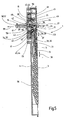
- FIG. 5 shows - in longitudinal section view - the internal structure of the rotary handle 1.
- the operating handle 3 is about a pivot axis 23 which is formed by a bearing pin 24, pivotable, the two pivot end positions (rest position and working position) from a comparison of Figures 5 and 6 evident.
- the bearing pin 24 is arranged on a torsion part 25, which is preferably rotatable about the rotation axis 17 by 360 °.
- a pivot member 26 is pivotally mounted.
- the bearing pin 24 passes through a receiving bore 27 of the pivoting element.
- the pivot member 26 Spaced to the pivot axis 23, the pivot member 26 has a control surface 28 which is formed as an inclined surface 29.
- the operating element 13 designed as a sliding element 14 is coupled to a slide 31, wherein the slide 31 is mounted longitudinally displaceable on the actuating handle 3 and preferably has a control surface 33 at one end 32, which is designed as an inclined surface 34.
- the slider 31 is biased by means of a spring 35, which is designed as a helical compression spring 36, in the direction of the operating element 13 (arrow 37).
- the helical compression spring 36 is supported both on the actuating handle 3, and on the slide 31.
- the trained as a sliding element 14 operating element 13 is in Direction of the double arrow 38 - as well as the slider 31 - slidably mounted on the operating handle 3.
- the control element 16 has the already mentioned square bolt 20, to which a cross-sectional larger circular cross-section 39 connects, which is rotatably mounted about the axis of rotation 17 in a bearing cup 40.
- the bearing cup 40 is located within the housing 4 in a rotationally fixed position. It has two diametrically opposite spring shafts 41. Further, the bearing cup 40 passes through the back 15 of the housing 4 with a tube extension 42.
- springs 43 are formed, which are formed as helical compression springs 44.
- the two helical compression springs 44 each act on a detent ball 45, wherein the two detent balls 45 - according to FIG.
- the flange 47 is designed substantially disc-shaped and connects to the circular cross-section 39 at.
- the flange 47 has on its rear side 48 a recess 49. From the rear 48 is a blind bore 50 extends, which is coaxial with the axis of rotation 17 and a spring 51 receives, which is designed as a helical compression spring 52 and a bearing ball 53 is applied, which thereby against the Twisted part 25 is urged and rests with a partial spherical surface in a shape-adapted bearing recess 54 of the VerFEteils 25.
- control element 16 Due to the action of the spring force of the helical compression spring 52, the control element 16 in the direction of the arrow 55 (FIG. FIG. 5 ). It is - depending on the operating condition - with its flange 47 on the bearing pot 40 and urges this also in the direction of the arrow 55, so that it is urged against the inside of the back 15 of the housing 4. It can be seen from all this that the control element 16 is mounted to a certain extent floating in the housing 4, so that any existing tolerances, positional errors and misalignment with respect to the coupling with the square bolt 20 can be compensated for the mentioned closure.
- the designed as a mounting housing 5 housing 4 can be fixed in the lowered position due to three mounting holes 56 by means of suitable mounting screws on said sliding leaf.
- “Countersink” means that the top of the front panel 6 is flush with or substantially flush with the corresponding surface of the sash.
- an inner bearing part 57 which consists of a first bearing part 58 and a second bearing part 59 and is screwed by means of four threaded screws 60 with the housing 4.
- the structure of the rotary handle 1 is in particular from the exploded view of FIG. 9 out.
- the rotary member 25 has bearing blocks 61, which are penetrated by the bearing pin 24.
- a friction ring 62 receives the edge of the torsion 25 and supports the torsion 25 in a receptacle 63 of the inner bearing part 15.
- One of the mounting holes 56 is formed in an insert 64, which is insertable into the housing 4.
- the slider 31 is held on the operating handle 3 by means of a back cover 65.
- the rocker-like pivot member 26 is associated with a spring 66 which, according to arrow 67 in FIG. 5 the Pivoting member 26 is rotated in the clockwise direction about the pivot axis 23, whereby the control surfaces 28 and 33 collide.
- a spring 68 which is formed as a helical compression spring 69, acts on the rear side of the actuating handle 23 by corresponding support on an inner surface of the housing 4 such that the actuating handle 3 about the pivot axis 23 in the direction of its rest position FIG. 5 is urged.
- a clip-on screw head cover 70 By means of a clip-on screw head cover 70, the associated mounting hole 56 can be covered.
- FIG. 5 goes again in perspective plan view and partial sectional view of the FIG. 10 out.
- the situation according to FIG. 6 also goes in perspective view and partial sectional view of the FIG. 11 out.
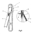
- the FIG. 7 illustrates the internal structure of the rotary handle 1 based on a partially cutaway perspective view of the rotary handle 1.
- the actuating handle 3 is in its rest position.
- FIG. 12 shows a rotational position of the operating handle 3 of the rotary handle 1, which from the situation according to FIG. 11 can be brought about.
- the user rotates - starting from the situation of the FIG. 11 -
- the actuating pin 3 about the axis of rotation 17.
- the pivot member 26 takes the control 16, so that by means of the square bolt 20, a closure of the wing can be operated.
- this allows the closure spend from its locking position in its unlocked position.
- it is - according to FIG.
- FIG. 14 It is also possible to make not only a 90 ° rotation of the operating handle 3 and the control element 16, but for example a 180 ° rotation. Also in the position of FIG. 14 a decoupling of the actuating handle 3 can be made by the control 16 by means of the operation of the control element 13.
- the operating element 13 is preferably actuated by means of the thumb of the user.
- the various angles of rotation are preferably characterized by slight latching effects of the latching balls 15, which can enter into correspondingly arranged latching recesses 46 of the flange 47 of the control element 16.
- the operating handle 3 from the position of FIG. 10 with actuated control element 13 first in the position of FIG. 11 spent, then - at a 90 ° twist - in the position according to FIG. 13 twisted, then through Actuation of the control element 13 brought about the coupling position with the control element 13 and then with entrainment of the control element 16 in the position according to FIG. 11 spent and then in the rest position according to FIG. 10 pivoted.
Landscapes
- Lock And Its Accessories (AREA)
- Window Of Vehicle (AREA)
- Wing Frames And Configurations (AREA)
- Power-Operated Mechanisms For Wings (AREA)
- Closing And Opening Devices For Wings, And Checks For Wings (AREA)
Claims (20)
- Poignée tournante pour une fermeture d'un vantail d'une fenêtre, d'une porte ou similaire, en particulier d'un vantail coulissant, comprenant une manette d'actionnement (3) qui peut être disposée, dans sa position de repos, encastrée dans le vantail au moins en partie en ce qui concerne sa hauteur et être sortie par pivotement de la position de repos à une position de travail en tant que poignée rabattable vers une position où elle est en saillie, ladite manette d'actionnement pouvant tourner autour d'un axe de rotation (17) dans la position de travail, et un élément de manoeuvre (13) permettant d'obtenir une position d'accouplement ou de désaccouplement par rapport à un élément de commande (16) pouvant tourner avec la manette d'actionnement (3) dans la position d'accouplement et ne pouvant pas tourner dans la position de désaccouplement, la manette d'actionnement (3) présentant l'élément de manoeuvre (13), caractérisée en ce que l'élément de manoeuvre (13) est un élément coulissant (14) et en ce que l'élément de manoeuvre (13) coopère avec un élément pivotant (26) qui est engagé avec l'élément de commande (16) dans une position d'accouplement et désengagé de l'élément de commande (16) dans une position de désaccouplement.
- Poignée tournante selon la revendication 1, caractérisée en ce que la manette d'actionnement (3) et/ou l'élément de manoeuvre (13) est une pièce actionnable manuellement, respectivement sont des pièces actionnables manuellement.
- Poignée tournante selon l'une des revendications précédentes, caractérisée en ce que l'élément pivotant (26) est monté de manière à pouvoir pivoter autour d'un axe de pivotement (23).
- Poignée tournante selon la revendication 3, caractérisée en ce que la manette d'actionnement (3) en tant que poignée rabattable (2) est montée rabattable autour de l'axe de pivotement (23).
- Poignée tournante selon l'une des revendications précédentes, caractérisée en ce que l'élément de manoeuvre (13) est accouplé à un coulisseau (31) ou présente le coulisseau (31), ledit coulisseau (31) coopérant avec l'élément pivotant (26).
- Poignée tournante selon l'une des revendications précédentes, caractérisée en ce que l'élément de commande (16) présente un évidement (49) dans lequel l'élément pivotant (26) pénètre pour provoquer la position d'accouplement et duquel l'élément pivotant (26) ressort pour provoquer la position de désaccouplement.
- Poignée tournante selon l'une des revendications précédentes, caractérisée en ce que l'élément pivotant (26) participe à la rotation lorsque la manette d'actionnement (3) est tournée autour de son axe de rotation (17).
- Poignée tournante selon l'une des revendications précédentes, caractérisée en ce que l'élément de manoeuvre (13) permet de provoquer la position d'accouplement ou de désaccouplement indépendamment de la position de rotation de la manette d'actionnement (3).
- Poignée tournante selon l'une des revendications précédentes, caractérisée en ce que l'élément de commande (16) présente un goujon de commande (18), en particulier un goujon polygonal (19).
- Poignée tournante selon l'une des revendications précédentes, caractérisée en ce que l'élément de commande (16) coopère avec un dispositif de position de verrouillage de rotation.
- Poignée tournante selon l'une des revendications précédentes, caractérisée par un boîtier (4) dans lequel la manette d'actionnement (3) peut être encastrée dans la position de repos, au moins en partie en ce qui concerne sa hauteur.
- Poignée tournante selon la revendication 11, caractérisée en ce que la manette d'actionnement (3) forme un angle aigu avec le boîtier (4) dans la position de travail.
- Poignée tournante selon l'une des revendications 11 ou 12, caractérisée en ce que le boîtier (4) est un boîtier encastré (5).
- Poignée tournante selon l'une des revendications 11 à 13, caractérisée en ce que l'élément de commande (16) est monté flottant dans le boîtier (4).
- Poignée tournante selon l'une des revendications 11 à 14, caractérisée en ce que l'élément de commande (16) est monté dans le boîtier (4) en étant chargé axialement par ressort au moyen d'un ressort (51).
- Poignée tournante selon la revendication 15, caractérisée en ce que le ressort (51) agit entre l'élément de commande (16) et une pièce tournante (25) montée de manière à pouvoir tourner dans le boîtier (4).
- Poignée tournante selon la revendication 16, caractérisée en ce que le ressort (51) charge une bille de support (53) qui s'appuie sur la pièce tournante (25) ou sur l'élément de commande (16).
- Poignée tournante selon la revendication 17, caractérisée en ce que la bille de support (53) pénètre avec une surface sphérique partielle dans un creux de support (54) de la pièce tournante (25) ou de l'élément de commande (16).
- Poignée tournante selon l'une des revendications 16 à 18, caractérisée en ce que la manette d'actionnement (3) est montée de manière à pouvoir pivoter sur la pièce tournante (25).
- Procédé pour actionner une fermeture d'un vantail d'une fenêtre, d'une porte ou similaire, en particulier d'un vantail coulissant, au moyen d'une poignée tournante selon l'une ou plusieurs des revendications précédentes.
Priority Applications (7)
| Application Number | Priority Date | Filing Date | Title |
|---|---|---|---|
| EP20070016030 EP2025837B1 (fr) | 2007-08-15 | 2007-08-15 | Poignée rotative pour la serrure d'une aile de fenêtre ou analogue et procédé d'actionnement de la serrure |
| ES07016030T ES2354295T3 (es) | 2007-08-15 | 2007-08-15 | Empuñadura giratoria para un cierre de una hoja de una ventana o similar, así como procedimiento para el accionamiento del cierre. |
| DE200750005420 DE502007005420D1 (de) | 2007-08-15 | 2007-08-15 | Drehhandhabe für einen Verschluss eines Flügels eines Fensters oder dergleichen sowie Verfahren zur Betätigung des Verschlusses |
| PL07016030T PL2025837T3 (pl) | 2007-08-15 | 2007-08-15 | Obrotowy uchwyt do zamknięcia skrzydła okna lub podobnego elementu oraz sposób uruchamiania zamknięcia |
| AT07016030T ATE485429T1 (de) | 2007-08-15 | 2007-08-15 | Drehhandhabe für einen verschluss eines flügels eines fensters oder dergleichen sowie verfahren zur betätigung des verschlusses |
| US12/221,786 US7958603B2 (en) | 2007-08-15 | 2008-08-05 | Rotary handle for a closing mechanism of a sash of a window or the like and method for actuating a closing mechanism |
| CN2008101470865A CN101368459B (zh) | 2007-08-15 | 2008-08-15 | 用于窗扇等的锁闭机构的旋转执手及驱动锁闭机构的方法 |
Applications Claiming Priority (1)
| Application Number | Priority Date | Filing Date | Title |
|---|---|---|---|
| EP20070016030 EP2025837B1 (fr) | 2007-08-15 | 2007-08-15 | Poignée rotative pour la serrure d'une aile de fenêtre ou analogue et procédé d'actionnement de la serrure |
Publications (2)
| Publication Number | Publication Date |
|---|---|
| EP2025837A1 EP2025837A1 (fr) | 2009-02-18 |
| EP2025837B1 true EP2025837B1 (fr) | 2010-10-20 |
Family
ID=39015720
Family Applications (1)
| Application Number | Title | Priority Date | Filing Date |
|---|---|---|---|
| EP20070016030 Not-in-force EP2025837B1 (fr) | 2007-08-15 | 2007-08-15 | Poignée rotative pour la serrure d'une aile de fenêtre ou analogue et procédé d'actionnement de la serrure |
Country Status (7)
| Country | Link |
|---|---|
| US (1) | US7958603B2 (fr) |
| EP (1) | EP2025837B1 (fr) |
| CN (1) | CN101368459B (fr) |
| AT (1) | ATE485429T1 (fr) |
| DE (1) | DE502007005420D1 (fr) |
| ES (1) | ES2354295T3 (fr) |
| PL (1) | PL2025837T3 (fr) |
Families Citing this family (14)
| Publication number | Priority date | Publication date | Assignee | Title |
|---|---|---|---|---|
| DE102009050815A1 (de) * | 2009-10-27 | 2011-04-28 | Emka Beschlagteile Gmbh & Co. Kg | Schwenkhebelverschluss mit geteilter Betätigungswelle |
| WO2011088234A1 (fr) * | 2010-01-18 | 2011-07-21 | John B. Higman And Valorie J. Higman; Trustees Of The Higman Family Trust U/D/T As Amended And | Poignée de porte coulissante rotative pouvant rentrer dans une cavité |
| GB201200977D0 (en) * | 2012-01-20 | 2012-03-07 | Banks J & Co Ltd | Operating handle for a folding/sliding door |
| PL2902572T3 (pl) * | 2014-01-30 | 2017-07-31 | Masterlab S.R.L. - Unipersonale | Urządzenie do poruszania elementów do ustawiania albo zamykania ramy okiennej albo drzwiowej |
| ITMI20140212U1 (it) * | 2014-06-30 | 2015-12-30 | Giussani Techniques S P A | Serratura per generatori da campo |
| GB2551592A (en) * | 2016-04-12 | 2017-12-27 | Thomas Rowlands Peter | Improvements in or relating to security |
| USD819425S1 (en) | 2016-12-29 | 2018-06-05 | Pella Corporation | Window operator |
| USD818798S1 (en) | 2016-12-29 | 2018-05-29 | Pella Corporation | Window operator |
| PL3569798T3 (pl) * | 2018-05-16 | 2024-07-29 | Industrilås I Nässjö Ab | Układ klamki podnoszonej |
| IT201800010575A1 (it) * | 2018-11-26 | 2020-05-26 | Fapim S P A | Maniglia per serramenti |
| EP3670327A1 (fr) * | 2018-12-19 | 2020-06-24 | Bombardier Inc. | Ensemble de poignée de porte d'aéronef |
| GB2580350A (en) * | 2019-01-03 | 2020-07-22 | Aanco Uk Ltd | Handle assembly |
| CN111058690B (zh) * | 2019-12-28 | 2025-02-14 | 森鹰窗业南京有限公司 | 用于门窗闭锁机构的推拉折叠执手 |
| US12421780B2 (en) * | 2023-10-05 | 2025-09-23 | Hoppe Holding Ag | Crank for window operator |
Family Cites Families (20)
| Publication number | Priority date | Publication date | Assignee | Title |
|---|---|---|---|---|
| DE59204071D1 (de) * | 1992-02-18 | 1995-11-23 | Webasto Karosseriesysteme | Kurbelantrieb für ein verstellbares Teil eines Fahrzeugdaches. |
| US5467503A (en) * | 1992-05-13 | 1995-11-21 | Truth Hardware Corporation | Handle and cover assembly for a window operator |
| US5230290A (en) * | 1992-06-09 | 1993-07-27 | Leggett & Platt Incorporated | Flush-mounted crank |
| JP2504713B2 (ja) * | 1993-03-09 | 1996-06-05 | タキゲン製造株式会社 | 引出し回転型扉用ロックハンドル装置 |
| JPH0752300Y2 (ja) * | 1993-05-11 | 1995-11-29 | タキゲン製造株式会社 | 平面ハンドル装置 |
| US5400473A (en) * | 1993-08-27 | 1995-03-28 | Great Lakes Window Inc. | Foldaway window crank handle with a handle retention spring |
| JP2623227B2 (ja) * | 1994-08-12 | 1997-06-25 | タキゲン製造株式会社 | 押釦式平面ハンドル装置 |
| US5560082A (en) * | 1994-09-15 | 1996-10-01 | Truth Hardware Corporation | Folding window operator handle |
| US5551316A (en) * | 1995-01-23 | 1996-09-03 | Blank; Jay L. | Retractable window crank |
| CN2371278Y (zh) * | 1998-12-22 | 2000-03-29 | 洪枝火 | 改良结构的锁 |
| JP2969119B1 (ja) * | 1998-12-22 | 1999-11-02 | タキゲン製造株式会社 | 引き出し回転操作型扉用ロックハンドル装置 |
| US6164156A (en) * | 1999-06-03 | 2000-12-26 | Newell Operating Company | Window operator |
| US20020066162A1 (en) * | 2000-12-06 | 2002-06-06 | Klompenburg Marlo G. Van | Casement window operator having folding crank handle |
| DE10204744B4 (de) | 2002-02-06 | 2010-11-04 | Wilhelm Weidtmann Gmbh & Co Kg | Verschluss an einem Flügel eines Fensters, einer Tür od. dgl. mit einem Klappgriff |
| DE10250960B4 (de) * | 2002-11-01 | 2019-06-13 | ABUS August Bremicker Söhne KG | Fenster-/Türgriff |
| CN2653053Y (zh) * | 2003-09-30 | 2004-11-03 | 江锦华 | 具锁控及电控的门扣 |
| DE102004006653A1 (de) * | 2004-02-11 | 2005-09-01 | Aug. Winkhaus Gmbh & Co. Kg | Antriebseinrichtung für einen Treibstangenbeschlag |
| US7147256B2 (en) * | 2004-03-26 | 2006-12-12 | Newell Operating Company | Fold down window operator |
| US20060260431A1 (en) * | 2005-05-17 | 2006-11-23 | Armada Toolworks Ltd. | Window handle |
| US7251860B2 (en) * | 2005-05-19 | 2007-08-07 | Luke Liang | Window rotating handle |
-
2007
- 2007-08-15 ES ES07016030T patent/ES2354295T3/es active Active
- 2007-08-15 PL PL07016030T patent/PL2025837T3/pl unknown
- 2007-08-15 AT AT07016030T patent/ATE485429T1/de active
- 2007-08-15 DE DE200750005420 patent/DE502007005420D1/de active Active
- 2007-08-15 EP EP20070016030 patent/EP2025837B1/fr not_active Not-in-force
-
2008
- 2008-08-05 US US12/221,786 patent/US7958603B2/en not_active Expired - Fee Related
- 2008-08-15 CN CN2008101470865A patent/CN101368459B/zh not_active Expired - Fee Related
Also Published As
| Publication number | Publication date |
|---|---|
| ATE485429T1 (de) | 2010-11-15 |
| CN101368459B (zh) | 2011-12-28 |
| ES2354295T3 (es) | 2011-03-11 |
| DE502007005420D1 (de) | 2010-12-02 |
| US20090044379A1 (en) | 2009-02-19 |
| PL2025837T3 (pl) | 2011-04-29 |
| CN101368459A (zh) | 2009-02-18 |
| US7958603B2 (en) | 2011-06-14 |
| EP2025837A1 (fr) | 2009-02-18 |
Similar Documents
| Publication | Publication Date | Title |
|---|---|---|
| EP2025837B1 (fr) | Poignée rotative pour la serrure d'une aile de fenêtre ou analogue et procédé d'actionnement de la serrure | |
| EP3615749B1 (fr) | Ferrure pour fênetre ou porte | |
| EP2692969B1 (fr) | Engrenage d'un dispositif de verrouillage à crémone, dispositif de verrouillage avec un tel engrenage ainsi que fenêtre, porte ou analogue avec un tel dispositif de verrouillage à crémone | |
| WO2017021410A1 (fr) | Élément d'actionnement pour une serrure à palastre | |
| DE3941923C2 (de) | Getriebe für Drehkipptüren | |
| EP1900891A2 (fr) | Fermeture à levier repliable | |
| EP4060147B1 (fr) | Dispositifs d'actionnement pour une serrure, ainsi que systèmes serrures pourvus de tels dispositifs d'actionnement | |
| DE10134249A1 (de) | Verriegelungsbeschlag mit drehbarer Riegelleiste | |
| EP0485767B1 (fr) | Verrouillage pour l'aile, en particulier l'aile coulissante d'une fenêtre, porte etc. | |
| EP1917413B1 (fr) | Dispositif de fermeture pour realiser le verrouillage multipoint de portes ou de parties de paroi dans des boitiers ou des armoires | |
| DE9007232U1 (de) | Treibstangenverschluß | |
| DE9208528U1 (de) | Einsteckschloß für eine Haustür oder Wohnungseingangstür | |
| DE10237492B3 (de) | Vorrichtung zum Öffnen und/oder Schließen eines Flügels relativ zu einem Rahmenstock | |
| DE29513227U1 (de) | Treibstangen-Antrieb | |
| DE3831529C2 (de) | Treibstangenverschluß | |
| DE69800295T2 (de) | Treibstangenbeschlag oder Treibstangenverschluß für Tür, Fenster oder dergl. | |
| EP4089253B1 (fr) | Système de fermeture et porte et fenêtre pourvues du système de fermeture | |
| EP4421270A1 (fr) | Garniture de porte et porte | |
| DE102020103758A1 (de) | Funktionseinheit | |
| EP1739260B1 (fr) | Transmission d'une ferrure pour fenêtre, portes, ou similaire, et procédé pour actionner la transmission | |
| DE102010055397B4 (de) | Verriegelungs-/Entriegelungsvorrichtung für eine Schiebetür und mit einer solchen Vorrichtung ausgestattete Tür | |
| DE10204744B4 (de) | Verschluss an einem Flügel eines Fensters, einer Tür od. dgl. mit einem Klappgriff | |
| EP1124033A2 (fr) | Ferrure oscillo-battante | |
| AT509464B1 (de) | Schloss | |
| DE69807801T2 (de) | Verriegelungsvorrichtung, insbesondere Einsteckschloss für den Flügel einer Tür oder eines Fensters |
Legal Events
| Date | Code | Title | Description |
|---|---|---|---|
| PUAI | Public reference made under article 153(3) epc to a published international application that has entered the european phase |
Free format text: ORIGINAL CODE: 0009012 |
|
| AK | Designated contracting states |
Kind code of ref document: A1 Designated state(s): AT BE BG CH CY CZ DE DK EE ES FI FR GB GR HU IE IS IT LI LT LU LV MC MT NL PL PT RO SE SI SK TR |
|
| AX | Request for extension of the european patent |
Extension state: AL BA HR MK RS |
|
| 17P | Request for examination filed |
Effective date: 20090818 |
|
| AKX | Designation fees paid |
Designated state(s): AT BE BG CH CY CZ DE DK EE ES FI FR GB GR HU IE IS IT LI LT LU LV MC MT NL PL PT RO SE SI SK TR |
|
| GRAP | Despatch of communication of intention to grant a patent |
Free format text: ORIGINAL CODE: EPIDOSNIGR1 |
|
| GRAS | Grant fee paid |
Free format text: ORIGINAL CODE: EPIDOSNIGR3 |
|
| GRAA | (expected) grant |
Free format text: ORIGINAL CODE: 0009210 |
|
| AK | Designated contracting states |
Kind code of ref document: B1 Designated state(s): AT BE BG CH CY CZ DE DK EE ES FI FR GB GR HU IE IS IT LI LT LU LV MC MT NL PL PT RO SE SI SK TR |
|
| REG | Reference to a national code |
Ref country code: GB Ref legal event code: FG4D Free format text: NOT ENGLISH |
|
| REG | Reference to a national code |
Ref country code: CH Ref legal event code: EP |
|
| REG | Reference to a national code |
Ref country code: IE Ref legal event code: FG4D Free format text: LANGUAGE OF EP DOCUMENT: GERMAN |
|
| REF | Corresponds to: |
Ref document number: 502007005420 Country of ref document: DE Date of ref document: 20101202 Kind code of ref document: P |
|
| REG | Reference to a national code |
Ref country code: CH Ref legal event code: NV Representative=s name: TROESCH SCHEIDEGGER WERNER AG |
|
| REG | Reference to a national code |
Ref country code: NL Ref legal event code: VDEP Effective date: 20101020 |
|
| REG | Reference to a national code |
Ref country code: ES Ref legal event code: FG2A Effective date: 20110301 |
|
| LTIE | Lt: invalidation of european patent or patent extension |
Effective date: 20101020 |
|
| PG25 | Lapsed in a contracting state [announced via postgrant information from national office to epo] |
Ref country code: LT Free format text: LAPSE BECAUSE OF FAILURE TO SUBMIT A TRANSLATION OF THE DESCRIPTION OR TO PAY THE FEE WITHIN THE PRESCRIBED TIME-LIMIT Effective date: 20101020 |
|
| REG | Reference to a national code |
Ref country code: PL Ref legal event code: T3 |
|
| REG | Reference to a national code |
Ref country code: IE Ref legal event code: FD4D |
|
| PG25 | Lapsed in a contracting state [announced via postgrant information from national office to epo] |
Ref country code: SE Free format text: LAPSE BECAUSE OF FAILURE TO SUBMIT A TRANSLATION OF THE DESCRIPTION OR TO PAY THE FEE WITHIN THE PRESCRIBED TIME-LIMIT Effective date: 20101020 Ref country code: NL Free format text: LAPSE BECAUSE OF FAILURE TO SUBMIT A TRANSLATION OF THE DESCRIPTION OR TO PAY THE FEE WITHIN THE PRESCRIBED TIME-LIMIT Effective date: 20101020 Ref country code: LV Free format text: LAPSE BECAUSE OF FAILURE TO SUBMIT A TRANSLATION OF THE DESCRIPTION OR TO PAY THE FEE WITHIN THE PRESCRIBED TIME-LIMIT Effective date: 20101020 Ref country code: BG Free format text: LAPSE BECAUSE OF FAILURE TO SUBMIT A TRANSLATION OF THE DESCRIPTION OR TO PAY THE FEE WITHIN THE PRESCRIBED TIME-LIMIT Effective date: 20110120 Ref country code: FI Free format text: LAPSE BECAUSE OF FAILURE TO SUBMIT A TRANSLATION OF THE DESCRIPTION OR TO PAY THE FEE WITHIN THE PRESCRIBED TIME-LIMIT Effective date: 20101020 Ref country code: PT Free format text: LAPSE BECAUSE OF FAILURE TO SUBMIT A TRANSLATION OF THE DESCRIPTION OR TO PAY THE FEE WITHIN THE PRESCRIBED TIME-LIMIT Effective date: 20110221 Ref country code: IS Free format text: LAPSE BECAUSE OF FAILURE TO SUBMIT A TRANSLATION OF THE DESCRIPTION OR TO PAY THE FEE WITHIN THE PRESCRIBED TIME-LIMIT Effective date: 20110220 Ref country code: SI Free format text: LAPSE BECAUSE OF FAILURE TO SUBMIT A TRANSLATION OF THE DESCRIPTION OR TO PAY THE FEE WITHIN THE PRESCRIBED TIME-LIMIT Effective date: 20101020 |
|
| REG | Reference to a national code |
Ref country code: HU Ref legal event code: AG4A Ref document number: E010287 Country of ref document: HU |
|
| PG25 | Lapsed in a contracting state [announced via postgrant information from national office to epo] |
Ref country code: GR Free format text: LAPSE BECAUSE OF FAILURE TO SUBMIT A TRANSLATION OF THE DESCRIPTION OR TO PAY THE FEE WITHIN THE PRESCRIBED TIME-LIMIT Effective date: 20110121 |
|
| PG25 | Lapsed in a contracting state [announced via postgrant information from national office to epo] |
Ref country code: EE Free format text: LAPSE BECAUSE OF FAILURE TO SUBMIT A TRANSLATION OF THE DESCRIPTION OR TO PAY THE FEE WITHIN THE PRESCRIBED TIME-LIMIT Effective date: 20101020 Ref country code: CZ Free format text: LAPSE BECAUSE OF FAILURE TO SUBMIT A TRANSLATION OF THE DESCRIPTION OR TO PAY THE FEE WITHIN THE PRESCRIBED TIME-LIMIT Effective date: 20101020 Ref country code: IE Free format text: LAPSE BECAUSE OF FAILURE TO SUBMIT A TRANSLATION OF THE DESCRIPTION OR TO PAY THE FEE WITHIN THE PRESCRIBED TIME-LIMIT Effective date: 20101020 |
|
| PLBE | No opposition filed within time limit |
Free format text: ORIGINAL CODE: 0009261 |
|
| STAA | Information on the status of an ep patent application or granted ep patent |
Free format text: STATUS: NO OPPOSITION FILED WITHIN TIME LIMIT |
|
| PG25 | Lapsed in a contracting state [announced via postgrant information from national office to epo] |
Ref country code: RO Free format text: LAPSE BECAUSE OF FAILURE TO SUBMIT A TRANSLATION OF THE DESCRIPTION OR TO PAY THE FEE WITHIN THE PRESCRIBED TIME-LIMIT Effective date: 20101020 Ref country code: DK Free format text: LAPSE BECAUSE OF FAILURE TO SUBMIT A TRANSLATION OF THE DESCRIPTION OR TO PAY THE FEE WITHIN THE PRESCRIBED TIME-LIMIT Effective date: 20101020 Ref country code: SK Free format text: LAPSE BECAUSE OF FAILURE TO SUBMIT A TRANSLATION OF THE DESCRIPTION OR TO PAY THE FEE WITHIN THE PRESCRIBED TIME-LIMIT Effective date: 20101020 |
|
| 26N | No opposition filed |
Effective date: 20110721 |
|
| REG | Reference to a national code |
Ref country code: DE Ref legal event code: R097 Ref document number: 502007005420 Country of ref document: DE Effective date: 20110721 |
|
| PG25 | Lapsed in a contracting state [announced via postgrant information from national office to epo] |
Ref country code: MT Free format text: LAPSE BECAUSE OF FAILURE TO SUBMIT A TRANSLATION OF THE DESCRIPTION OR TO PAY THE FEE WITHIN THE PRESCRIBED TIME-LIMIT Effective date: 20101020 |
|
| BERE | Be: lapsed |
Owner name: ROTO FRANK A.G. Effective date: 20110831 |
|
| PG25 | Lapsed in a contracting state [announced via postgrant information from national office to epo] |
Ref country code: MC Free format text: LAPSE BECAUSE OF NON-PAYMENT OF DUE FEES Effective date: 20110831 |
|
| PG25 | Lapsed in a contracting state [announced via postgrant information from national office to epo] |
Ref country code: BE Free format text: LAPSE BECAUSE OF NON-PAYMENT OF DUE FEES Effective date: 20110831 |
|
| PG25 | Lapsed in a contracting state [announced via postgrant information from national office to epo] |
Ref country code: LU Free format text: LAPSE BECAUSE OF NON-PAYMENT OF DUE FEES Effective date: 20110815 Ref country code: CY Free format text: LAPSE BECAUSE OF EXPIRATION OF PROTECTION Effective date: 20101020 |
|
| REG | Reference to a national code |
Ref country code: FR Ref legal event code: PLFP Year of fee payment: 10 |
|
| PGFP | Annual fee paid to national office [announced via postgrant information from national office to epo] |
Ref country code: IT Payment date: 20160823 Year of fee payment: 10 Ref country code: CH Payment date: 20160819 Year of fee payment: 10 |
|
| PGFP | Annual fee paid to national office [announced via postgrant information from national office to epo] |
Ref country code: HU Payment date: 20160823 Year of fee payment: 10 |
|
| REG | Reference to a national code |
Ref country code: FR Ref legal event code: PLFP Year of fee payment: 11 |
|
| REG | Reference to a national code |
Ref country code: CH Ref legal event code: PL |
|
| PG25 | Lapsed in a contracting state [announced via postgrant information from national office to epo] |
Ref country code: LI Free format text: LAPSE BECAUSE OF NON-PAYMENT OF DUE FEES Effective date: 20170831 Ref country code: CH Free format text: LAPSE BECAUSE OF NON-PAYMENT OF DUE FEES Effective date: 20170831 Ref country code: HU Free format text: LAPSE BECAUSE OF NON-PAYMENT OF DUE FEES Effective date: 20170816 |
|
| REG | Reference to a national code |
Ref country code: FR Ref legal event code: PLFP Year of fee payment: 12 |
|
| PG25 | Lapsed in a contracting state [announced via postgrant information from national office to epo] |
Ref country code: IT Free format text: LAPSE BECAUSE OF NON-PAYMENT OF DUE FEES Effective date: 20170815 |
|
| PGFP | Annual fee paid to national office [announced via postgrant information from national office to epo] |
Ref country code: FR Payment date: 20180827 Year of fee payment: 12 |
|
| PGFP | Annual fee paid to national office [announced via postgrant information from national office to epo] |
Ref country code: GB Payment date: 20180822 Year of fee payment: 12 |
|
| PGFP | Annual fee paid to national office [announced via postgrant information from national office to epo] |
Ref country code: PL Payment date: 20190813 Year of fee payment: 13 |
|
| REG | Reference to a national code |
Ref country code: AT Ref legal event code: MM01 Ref document number: 485429 Country of ref document: AT Kind code of ref document: T Effective date: 20190815 |
|
| GBPC | Gb: european patent ceased through non-payment of renewal fee |
Effective date: 20190815 |
|
| PG25 | Lapsed in a contracting state [announced via postgrant information from national office to epo] |
Ref country code: AT Free format text: LAPSE BECAUSE OF NON-PAYMENT OF DUE FEES Effective date: 20190815 |
|
| PG25 | Lapsed in a contracting state [announced via postgrant information from national office to epo] |
Ref country code: FR Free format text: LAPSE BECAUSE OF NON-PAYMENT OF DUE FEES Effective date: 20190831 |
|
| PG25 | Lapsed in a contracting state [announced via postgrant information from national office to epo] |
Ref country code: GB Free format text: LAPSE BECAUSE OF NON-PAYMENT OF DUE FEES Effective date: 20190815 |
|
| PGFP | Annual fee paid to national office [announced via postgrant information from national office to epo] |
Ref country code: TR Payment date: 20200813 Year of fee payment: 14 |
|
| REG | Reference to a national code |
Ref country code: ES Ref legal event code: FD2A Effective date: 20210107 |
|
| PG25 | Lapsed in a contracting state [announced via postgrant information from national office to epo] |
Ref country code: ES Free format text: LAPSE BECAUSE OF NON-PAYMENT OF DUE FEES Effective date: 20190816 |
|
| PG25 | Lapsed in a contracting state [announced via postgrant information from national office to epo] |
Ref country code: PL Free format text: LAPSE BECAUSE OF NON-PAYMENT OF DUE FEES Effective date: 20200815 |
|
| PGFP | Annual fee paid to national office [announced via postgrant information from national office to epo] |
Ref country code: DE Payment date: 20230822 Year of fee payment: 17 |
|
| PG25 | Lapsed in a contracting state [announced via postgrant information from national office to epo] |
Ref country code: TR Free format text: LAPSE BECAUSE OF NON-PAYMENT OF DUE FEES Effective date: 20210815 |
|
| REG | Reference to a national code |
Ref country code: DE Ref legal event code: R119 Ref document number: 502007005420 Country of ref document: DE |
|
| PG25 | Lapsed in a contracting state [announced via postgrant information from national office to epo] |
Ref country code: DE Free format text: LAPSE BECAUSE OF NON-PAYMENT OF DUE FEES Effective date: 20250301 |