EP2026044B1 - Extrémité pour un dispositif de dosage destiné au dosage d'un fluide - Google Patents
Extrémité pour un dispositif de dosage destiné au dosage d'un fluide Download PDFInfo
- Publication number
- EP2026044B1 EP2026044B1 EP20070113872 EP07113872A EP2026044B1 EP 2026044 B1 EP2026044 B1 EP 2026044B1 EP 20070113872 EP20070113872 EP 20070113872 EP 07113872 A EP07113872 A EP 07113872A EP 2026044 B1 EP2026044 B1 EP 2026044B1
- Authority
- EP
- European Patent Office
- Prior art keywords
- end piece
- metering
- coupling means
- fluid
- cone
- Prior art date
- Legal status (The legal status is an assumption and is not a legal conclusion. Google has not performed a legal analysis and makes no representation as to the accuracy of the status listed.)
- Active
Links
Images


Classifications
-
- G—PHYSICS
- G01—MEASURING; TESTING
- G01F—MEASURING VOLUME, VOLUME FLOW, MASS FLOW OR LIQUID LEVEL; METERING BY VOLUME
- G01F11/00—Apparatus requiring external operation adapted at each repeated and identical operation to measure and separate a predetermined volume of fluid or fluent solid material from a supply or container, without regard to weight, and to deliver it
- G01F11/02—Apparatus requiring external operation adapted at each repeated and identical operation to measure and separate a predetermined volume of fluid or fluent solid material from a supply or container, without regard to weight, and to deliver it with measuring chambers which expand or contract during measurement
- G01F11/021—Apparatus requiring external operation adapted at each repeated and identical operation to measure and separate a predetermined volume of fluid or fluent solid material from a supply or container, without regard to weight, and to deliver it with measuring chambers which expand or contract during measurement of the piston type
- G01F11/029—Apparatus requiring external operation adapted at each repeated and identical operation to measure and separate a predetermined volume of fluid or fluent solid material from a supply or container, without regard to weight, and to deliver it with measuring chambers which expand or contract during measurement of the piston type provided with electric controlling means
-
- F—MECHANICAL ENGINEERING; LIGHTING; HEATING; WEAPONS; BLASTING
- F04—POSITIVE - DISPLACEMENT MACHINES FOR LIQUIDS; PUMPS FOR LIQUIDS OR ELASTIC FLUIDS
- F04C—ROTARY-PISTON, OR OSCILLATING-PISTON, POSITIVE-DISPLACEMENT MACHINES FOR LIQUIDS; ROTARY-PISTON, OR OSCILLATING-PISTON, POSITIVE-DISPLACEMENT PUMPS
- F04C2/00—Rotary-piston machines or pumps
- F04C2/08—Rotary-piston machines or pumps of intermeshing-engagement type, i.e. with engagement of co-operating members similar to that of toothed gearing
- F04C2/10—Rotary-piston machines or pumps of intermeshing-engagement type, i.e. with engagement of co-operating members similar to that of toothed gearing of internal-axis type with the outer member having more teeth or tooth-equivalents, e.g. rollers, than the inner member
- F04C2/107—Rotary-piston machines or pumps of intermeshing-engagement type, i.e. with engagement of co-operating members similar to that of toothed gearing of internal-axis type with the outer member having more teeth or tooth-equivalents, e.g. rollers, than the inner member with helical teeth
- F04C2/1071—Rotary-piston machines or pumps of intermeshing-engagement type, i.e. with engagement of co-operating members similar to that of toothed gearing of internal-axis type with the outer member having more teeth or tooth-equivalents, e.g. rollers, than the inner member with helical teeth the inner and outer member having a different number of threads and one of the two being made of elastic materials, e.g. Moineau type
-
- F—MECHANICAL ENGINEERING; LIGHTING; HEATING; WEAPONS; BLASTING
- F04—POSITIVE - DISPLACEMENT MACHINES FOR LIQUIDS; PUMPS FOR LIQUIDS OR ELASTIC FLUIDS
- F04C—ROTARY-PISTON, OR OSCILLATING-PISTON, POSITIVE-DISPLACEMENT MACHINES FOR LIQUIDS; ROTARY-PISTON, OR OSCILLATING-PISTON, POSITIVE-DISPLACEMENT PUMPS
- F04C2220/00—Application
- F04C2220/24—Application for metering throughflow
Definitions
- the technical field of the invention relates to the metering of fluids or fluid media, such as adhesives or sealants, paints, suspensions, viscous raw materials, emulsions or fats.
- Dosing devices which are suitable for such a dosage can be based on a gear pump or an eccentric screw pump or designed, for example, as a spindle conveyor.
- Such a metering device can also be designed as a valve, for example as a spindle valve, as a pressure-time valve or as a volume valve.
- the publication DE 20 2004 002 167 U1 which is considered to be the closest prior art, describes a metering valve for discharging minute amounts of medium onto a workpiece in the jet process, with a valve head having an outlet opening and a valve element associated therewith for opening and closing the outlet opening, and a jet device associated with the valve head, by means of which the medium in the form of droplets and / or jetsrank think- from the valve head or is injectable, with a dispensing needle sits on the valve head, which is designed in the manner of a nozzle such that the medium in the form of droplets and / or Rays from the dispensing needle can be ejected.
- Another object is to provide a solution that is as simple as possible and / or minimized in terms of the necessary installation space To suggest detection of disturbances during metering of the fluid through the metering device.
- the third coupling means and the fourth coupling means form a screw connection.
- the end piece is adapted to tension a stator of an eccentric screw pump of the metering device.
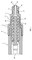
- All embodiments of the invention according to the Fig. 1 to 6 have in common that the tail 1, a first coupling means 3, which is adapted to couple the tail 1 with the metering device 2, an integrated needle adapter 4, which is adapted to couple a dispensing needle with the end piece 1, and an integrated pressure sensor device 5 or a second coupling means 6, which is adapted to couple the end piece 1 with the pressure sensor device 5.
- the third coupling means 7a are configured as a female luer taper 7a and the fourth coupling means 8a are designed as a male male tapered luer cone 8a.
- a channel 17 is provided for performing the funded by the metering device 2 fluid in the dispensing needle at least in the Luer cone 7a with female inner cone.
- the channel 17 preferably has at its outer diameter a groove 15 and an O-ring 16 arranged in the groove 15 for sealing the Luer-lock 7a formed from the Luer cone 7a with a female inner cone and from the Luer cone 7b with a male outer cone. 8a on.
- the O-ring 16 is made of, for example, an elastomer or rubber.
- the pressure sensor is particularly suitable for measuring a metering pressure during metering of the fluid. Furthermore, the detection means is preferably suitable for detecting a disturbance, for example an air bubble in the fluid or a fluctuation of the metering pressure, as a function of the measured metering pressure.
- Fig. 6 is a schematic perspective view of a fourth embodiment of the end piece 1 according to the invention shown.
- the fourth embodiment according to Fig. 6 differs from the third embodiment according to Fig. 5 in that not a second coupling means 6 is provided for coupling a pressure sensor device 5, but that the pressure sensor device 5 is integrated in the end piece 1.
- the end piece 1 according to Fig. 6 in addition to the first coupling means 3, which may be formed in particular as a connector on an outer diameter of the pressure sensor device 2, an integrated needle adapter 4 for coupling the dispensing needle and an integrated pressure sensor device 5.
Landscapes
- Physics & Mathematics (AREA)
- Fluid Mechanics (AREA)
- General Physics & Mathematics (AREA)
- Infusion, Injection, And Reservoir Apparatuses (AREA)
Claims (10)
- Embout (1) pour un dispositif de dosage (2) permettant de doser un fluide, comprenant :- un premier élément d'accouplement (3), qui sert à accoupler l'embout (1) au dispositif de dosage (2) ;
caractérisé par- un adaptateur d' aiguille intégré (4), qui sert à accoupler une aiguille de dosage à l'embout (1) ; et- un dispositif à capteur de pression intégré (5) ou un second élément d'accouplement (6), qui sert à accoupler l'embout (1) à un dispositif à capteur de pression (5). - Embout selon la revendication 1, caractérisé en ce que l'embout (1) est constitué de deux parties, une première partie (1a) présentant le premier élément d'accouplement (3) et un troisième élément d'accouplement (7a, 7b) et la deuxième partie (1b) présentant l'adaptateur d'aiguille intégré (4) ou une aiguille d'injection intégrée, le dispositif à capteur de pression intégré (5) ou le second élément d'accouplement (6) et un quatrième élément d'accouplement (8a, 8b) qui peut être accouplé au troisième élément d'accouplement (7a, 7b).
- Embout selon la revendication 2, caractérisé en ce que le troisième élément d'accouplement (7a, 7b) est réalisé sous forme de cône Luer (7a) à cône interne femelle et le quatrième élément d'accouplement (8a, 8b) est réalisé sous forme de cône Luer (8a) à cône externe mâle.
- Embout selon la revendication 3, caractérisé en ce qu'un canal (17) permettant d'acheminer le fluide véhiculé par le dispositif de dosage (2) dans l'aiguille de dosage présente, au moins dans le cône Luer (7a) à cône interne femelle, une rainure (15) et un joint torique (16) disposé dans la rainure (15) afin d'assurer l'étanchéité du système de verrouillage Luer (7a, 8a) formé par le cône Luer (7a) à cône interne femelle et le cône Luer (7b) à cône externe mâle.
- Embout selon la revendication 2, caractérisé en ce que le troisième élément d'accouplement (7a, 7b) et le quatrième élément d'accouplement (8a, 8b) forment un assemblage vissé (7b, 8b).
- Embout selon la revendication 1, caractérisé en ce que l'embout (1) est constitué d'un seul tenant.
- Embout selon la revendication 1 ou l'une des revendications 2 à 6, caractérisé en ce qu'il est prévu un écrou-raccord (9) qui peut être vissé sur un filetage extérieur de l'embout (1) et sur un filetage extérieur du dispositif de dosage (2).
- Embout selon la revendication 1 ou l'une des revendications 2 à 7, caractérisé en ce que l'embout (1) permet de serrer un stator (10) d'une pompe à vis sans fin excentrique (11) du dispositif de dosage (2).
- Embout selon la revendication 1 ou l'une des revendications 2 à 8, caractérisé en ce que le dispositif à capteur de pression (5) sert à commander une pression de dosage fournie par le dispositif de dosage (2) pendant un dosage du fluide.
- Embout selon la revendication 1 ou l'une des revendications 2 à 9, caractérisé en ce que le dispositif à capteur de pression (5) présente :- un capteur de pression, qui mesure une pression de dosage pendant un dosage du fluide ; et- un élément de détection, qui sert à détecter, en fonction de la pression de dosage mesurée, une défaillance, par exemple une bulle d'air dans le fluide ou une fluctuation de la pression de dosage.
Priority Applications (2)
| Application Number | Priority Date | Filing Date | Title |
|---|---|---|---|
| EP20070113872 EP2026044B1 (fr) | 2007-08-06 | 2007-08-06 | Extrémité pour un dispositif de dosage destiné au dosage d'un fluide |
| DE200750004337 DE502007004337D1 (de) | 2007-08-06 | 2007-08-06 | Endstück für eine Dosiervorrichtung zum Dosieren eines Fluids |
Applications Claiming Priority (1)
| Application Number | Priority Date | Filing Date | Title |
|---|---|---|---|
| EP20070113872 EP2026044B1 (fr) | 2007-08-06 | 2007-08-06 | Extrémité pour un dispositif de dosage destiné au dosage d'un fluide |
Publications (2)
| Publication Number | Publication Date |
|---|---|
| EP2026044A1 EP2026044A1 (fr) | 2009-02-18 |
| EP2026044B1 true EP2026044B1 (fr) | 2010-07-07 |
Family
ID=38984290
Family Applications (1)
| Application Number | Title | Priority Date | Filing Date |
|---|---|---|---|
| EP20070113872 Active EP2026044B1 (fr) | 2007-08-06 | 2007-08-06 | Extrémité pour un dispositif de dosage destiné au dosage d'un fluide |
Country Status (2)
| Country | Link |
|---|---|
| EP (1) | EP2026044B1 (fr) |
| DE (1) | DE502007004337D1 (fr) |
Cited By (1)
| Publication number | Priority date | Publication date | Assignee | Title |
|---|---|---|---|---|
| EP3940232B1 (fr) * | 2019-03-15 | 2026-01-07 | Agostini, Leandro José | Pompe à cavité progressive pour l'industrie tintométrique |
Families Citing this family (4)
| Publication number | Priority date | Publication date | Assignee | Title |
|---|---|---|---|---|
| EP3331651A1 (fr) * | 2015-08-05 | 2018-06-13 | Nordson Corporation | Système de distribution de jets comprenant une alimentation par une pompe à vis excentrée et procédés associés |
| US11320295B2 (en) * | 2019-04-26 | 2022-05-03 | Festo Se & Co. Kg | Dosing unit and method for dosing a liquid |
| USD971967S1 (en) * | 2020-02-13 | 2022-12-06 | Viscotec Pumpen—Und Dosiertechnik Gmbh | Metering pump |
| JP1749404S (ja) * | 2021-09-30 | 2023-07-27 | 計量器 |
Family Cites Families (4)
| Publication number | Priority date | Publication date | Assignee | Title |
|---|---|---|---|---|
| US5615801A (en) | 1990-06-06 | 1997-04-01 | The Coca-Cola Company | Juice concentrate package for postmix dispenser |
| US5305923A (en) | 1990-06-06 | 1994-04-26 | The Coca-Cola Company | Postmix beverage dispensing system |
| DE19857338C1 (de) | 1998-12-11 | 2000-10-05 | Siemens Ag | Dosiervorrichtung |
| DE202004002167U1 (de) | 2004-02-12 | 2004-06-03 | Pico Dosiertechnik Gmbh | Dosierventil |
-
2007
- 2007-08-06 EP EP20070113872 patent/EP2026044B1/fr active Active
- 2007-08-06 DE DE200750004337 patent/DE502007004337D1/de active Active
Cited By (1)
| Publication number | Priority date | Publication date | Assignee | Title |
|---|---|---|---|---|
| EP3940232B1 (fr) * | 2019-03-15 | 2026-01-07 | Agostini, Leandro José | Pompe à cavité progressive pour l'industrie tintométrique |
Also Published As
| Publication number | Publication date |
|---|---|
| EP2026044A1 (fr) | 2009-02-18 |
| DE502007004337D1 (de) | 2010-08-19 |
Similar Documents
| Publication | Publication Date | Title |
|---|---|---|
| DE68906660T2 (de) | Vorrichtung zur umwandlung einer laminaren stroemung in tropfen. | |
| EP2026044B1 (fr) | Extrémité pour un dispositif de dosage destiné au dosage d'un fluide | |
| DE2622396A1 (de) | Spritzduese | |
| EP1101931A2 (fr) | Système d'injection à haute pression avec common rail | |
| EP3225315B1 (fr) | Procede et dispositif de dosage destine au dosage reglable en pression d'un produit liquide ou pateux | |
| DE3110907C2 (fr) | ||
| DE102014010843A1 (de) | Dosierdüse und Verfahren zum dosierten Auftragen hochviskoser Medien | |
| EP2022571A1 (fr) | Dispositif de dosage destiné au dosage d'un liquide | |
| EP2377623B1 (fr) | Dispositif d'application d'une matière liquide sur un substrat | |
| AT512960B1 (de) | Injektor eines modularen Common-Rail-Kraftstoffeinspritzsystems | |
| DE102015105121A1 (de) | Farbsprüheinrichtung | |
| DE4441505A1 (de) | Kraftstoff-Förderpumpe für eine Kraftstoffeinspritzpumpe für Brennkraftmaschinen | |
| EP1034380B1 (fr) | Appariement filete assurant une etancheite | |
| WO2010083824A1 (fr) | Système de montage | |
| AT518782B1 (de) | Schaumaufbereitungsvorrichtung | |
| DE4224664A1 (de) | Rotordüse, insbesondere für ein mit Reinigungsflüssigkeit arbeitendes Hochdruckreinigungsgerät | |
| DE10005105B4 (de) | Fluidpistole mit Dosierrohr | |
| EP3838372B1 (fr) | Dispositif filtrant | |
| DE3137074C2 (de) | Anlage zum elektrostatischen Beschichten von Werkstücken mit einer Flüssigkeit | |
| DE202004002167U1 (de) | Dosierventil | |
| DE102004062008A1 (de) | Kraftstofffilter mit Auslassöffnungen, die vorzugsweise mit einem hydroerosiven Verfahren bearbeitet sind | |
| DE102023120622B3 (de) | Leckageprüfvorrichtung | |
| DE1632430C3 (de) | Einrichtung zum Vermischen eines unter Druck stehenden Gasstroms mit einem feinverteilten Nebel eines flüssigen Mittels, beispielsweise Schmieröls | |
| EP2042791B1 (fr) | Soupape latérale | |
| DE2117674A1 (de) | Vorrichtung zum Verändern der Strömungsgeschwindigkeit eines Fluids |
Legal Events
| Date | Code | Title | Description |
|---|---|---|---|
| PUAI | Public reference made under article 153(3) epc to a published international application that has entered the european phase |
Free format text: ORIGINAL CODE: 0009012 |
|
| 17P | Request for examination filed |
Effective date: 20080506 |
|
| AK | Designated contracting states |
Kind code of ref document: A1 Designated state(s): AT BE BG CH CY CZ DE DK EE ES FI FR GB GR HU IE IS IT LI LT LU LV MC MT NL PL PT RO SE SI SK TR |
|
| AX | Request for extension of the european patent |
Extension state: AL BA HR MK RS |
|
| AKX | Designation fees paid |
Designated state(s): CZ DE FR GB HU IT |
|
| GRAP | Despatch of communication of intention to grant a patent |
Free format text: ORIGINAL CODE: EPIDOSNIGR1 |
|
| GRAS | Grant fee paid |
Free format text: ORIGINAL CODE: EPIDOSNIGR3 |
|
| GRAA | (expected) grant |
Free format text: ORIGINAL CODE: 0009210 |
|
| AK | Designated contracting states |
Kind code of ref document: B1 Designated state(s): CZ DE FR GB HU IT |
|
| REG | Reference to a national code |
Ref country code: GB Ref legal event code: FG4D Free format text: NOT ENGLISH |
|
| REF | Corresponds to: |
Ref document number: 502007004337 Country of ref document: DE Date of ref document: 20100819 Kind code of ref document: P |
|
| PLBE | No opposition filed within time limit |
Free format text: ORIGINAL CODE: 0009261 |
|
| STAA | Information on the status of an ep patent application or granted ep patent |
Free format text: STATUS: NO OPPOSITION FILED WITHIN TIME LIMIT |
|
| PG25 | Lapsed in a contracting state [announced via postgrant information from national office to epo] |
Ref country code: IT Free format text: LAPSE BECAUSE OF FAILURE TO SUBMIT A TRANSLATION OF THE DESCRIPTION OR TO PAY THE FEE WITHIN THE PRESCRIBED TIME-LIMIT Effective date: 20100707 Ref country code: CZ Free format text: LAPSE BECAUSE OF FAILURE TO SUBMIT A TRANSLATION OF THE DESCRIPTION OR TO PAY THE FEE WITHIN THE PRESCRIBED TIME-LIMIT Effective date: 20100707 |
|
| 26N | No opposition filed |
Effective date: 20110408 |
|
| REG | Reference to a national code |
Ref country code: DE Ref legal event code: R097 Ref document number: 502007004337 Country of ref document: DE Effective date: 20110408 |
|
| REG | Reference to a national code |
Ref country code: DE Ref legal event code: R082 Ref document number: 502007004337 Country of ref document: DE Representative=s name: HORN KLEIMANN WAITZHOFER, PATENTANWAELTE, DE Ref country code: DE Ref legal event code: R082 Ref document number: 502007004337 Country of ref document: DE Representative=s name: HORN KLEIMANN WAITZHOFER PATENTANWAELTE, DE Ref country code: DE Ref legal event code: R082 Ref document number: 502007004337 Country of ref document: DE Representative=s name: HORN KLEIMANN WAITZHOFER PATENTANWAELTE PARTG , DE |
|
| PG25 | Lapsed in a contracting state [announced via postgrant information from national office to epo] |
Ref country code: HU Free format text: LAPSE BECAUSE OF FAILURE TO SUBMIT A TRANSLATION OF THE DESCRIPTION OR TO PAY THE FEE WITHIN THE PRESCRIBED TIME-LIMIT Effective date: 20110108 |
|
| REG | Reference to a national code |
Ref country code: FR Ref legal event code: PLFP Year of fee payment: 10 |
|
| REG | Reference to a national code |
Ref country code: FR Ref legal event code: PLFP Year of fee payment: 11 |
|
| REG | Reference to a national code |
Ref country code: FR Ref legal event code: PLFP Year of fee payment: 12 |
|
| PGFP | Annual fee paid to national office [announced via postgrant information from national office to epo] |
Ref country code: DE Payment date: 20250825 Year of fee payment: 19 |
|
| PGFP | Annual fee paid to national office [announced via postgrant information from national office to epo] |
Ref country code: GB Payment date: 20250822 Year of fee payment: 19 |
|
| PGFP | Annual fee paid to national office [announced via postgrant information from national office to epo] |
Ref country code: FR Payment date: 20250821 Year of fee payment: 19 |