EP2030930B1 - Blatt-/Seitenzwischenspeicher für Blatthandhabungsvorrichtung - Google Patents
Blatt-/Seitenzwischenspeicher für Blatthandhabungsvorrichtung Download PDFInfo
- Publication number
- EP2030930B1 EP2030930B1 EP08014767.1A EP08014767A EP2030930B1 EP 2030930 B1 EP2030930 B1 EP 2030930B1 EP 08014767 A EP08014767 A EP 08014767A EP 2030930 B1 EP2030930 B1 EP 2030930B1
- Authority
- EP
- European Patent Office
- Prior art keywords
- page
- printed
- pages
- rollers
- stations
- Prior art date
- Legal status (The legal status is an assumption and is not a legal conclusion. Google has not performed a legal analysis and makes no representation as to the accuracy of the status listed.)
- Ceased
Links
- 239000000872 buffer Substances 0.000 title claims description 71
- 238000011144 upstream manufacturing Methods 0.000 claims description 18
- 238000012545 processing Methods 0.000 claims description 12
- 239000000463 material Substances 0.000 description 32
- 238000000034 method Methods 0.000 description 12
- 230000008569 process Effects 0.000 description 8
- 238000013461 design Methods 0.000 description 7
- 238000004519 manufacturing process Methods 0.000 description 5
- 230000007246 mechanism Effects 0.000 description 5
- 230000008859 change Effects 0.000 description 4
- 238000004891 communication Methods 0.000 description 3
- 238000005096 rolling process Methods 0.000 description 3
- 239000011800 void material Substances 0.000 description 2
- 239000007853 buffer solution Substances 0.000 description 1
- 230000003139 buffering effect Effects 0.000 description 1
- 238000006243 chemical reaction Methods 0.000 description 1
- 238000006073 displacement reaction Methods 0.000 description 1
- 230000006870 function Effects 0.000 description 1
- 238000012423 maintenance Methods 0.000 description 1
- 238000012986 modification Methods 0.000 description 1
- 230000004048 modification Effects 0.000 description 1
- 239000002994 raw material Substances 0.000 description 1
Images


Classifications
-
- B—PERFORMING OPERATIONS; TRANSPORTING
- B65—CONVEYING; PACKING; STORING; HANDLING THIN OR FILAMENTARY MATERIAL
- B65H—HANDLING THIN OR FILAMENTARY MATERIAL, e.g. SHEETS, WEBS, CABLES
- B65H29/00—Delivering or advancing articles from machines; Advancing articles to or into piles
- B65H29/12—Delivering or advancing articles from machines; Advancing articles to or into piles by means of the nip between two, or between two sets of, moving tapes or bands or rollers
-
- B—PERFORMING OPERATIONS; TRANSPORTING
- B65—CONVEYING; PACKING; STORING; HANDLING THIN OR FILAMENTARY MATERIAL
- B65H—HANDLING THIN OR FILAMENTARY MATERIAL, e.g. SHEETS, WEBS, CABLES
- B65H39/00—Associating, collating, or gathering articles or webs
- B65H39/10—Associating articles from a single source, to form, e.g. a writing-pad
-
- B—PERFORMING OPERATIONS; TRANSPORTING
- B65—CONVEYING; PACKING; STORING; HANDLING THIN OR FILAMENTARY MATERIAL
- B65H—HANDLING THIN OR FILAMENTARY MATERIAL, e.g. SHEETS, WEBS, CABLES
- B65H2220/00—Function indicators
- B65H2220/09—Function indicators indicating that several of an entity are present
-
- B—PERFORMING OPERATIONS; TRANSPORTING
- B65—CONVEYING; PACKING; STORING; HANDLING THIN OR FILAMENTARY MATERIAL
- B65H—HANDLING THIN OR FILAMENTARY MATERIAL, e.g. SHEETS, WEBS, CABLES
- B65H2301/00—Handling processes for sheets or webs
- B65H2301/40—Type of handling process
- B65H2301/43—Gathering; Associating; Assembling
- B65H2301/431—Features with regard to the collection, nature, sequence and/or the making thereof
- B65H2301/4312—Gathering material delivered from a digital printing machine
-
- B—PERFORMING OPERATIONS; TRANSPORTING
- B65—CONVEYING; PACKING; STORING; HANDLING THIN OR FILAMENTARY MATERIAL
- B65H—HANDLING THIN OR FILAMENTARY MATERIAL, e.g. SHEETS, WEBS, CABLES
- B65H2301/00—Handling processes for sheets or webs
- B65H2301/40—Type of handling process
- B65H2301/43—Gathering; Associating; Assembling
- B65H2301/431—Features with regard to the collection, nature, sequence and/or the making thereof
- B65H2301/4318—Gathering, associating, assembling articles from a single source which is supplied by several sources
-
- B—PERFORMING OPERATIONS; TRANSPORTING
- B65—CONVEYING; PACKING; STORING; HANDLING THIN OR FILAMENTARY MATERIAL
- B65H—HANDLING THIN OR FILAMENTARY MATERIAL, e.g. SHEETS, WEBS, CABLES
- B65H2301/00—Handling processes for sheets or webs
- B65H2301/40—Type of handling process
- B65H2301/44—Moving, forwarding, guiding material
- B65H2301/445—Moving, forwarding, guiding material stream of articles separated from each other
- B65H2301/4453—Moving, forwarding, guiding material stream of articles separated from each other and performing dynamic accumulation
-
- B—PERFORMING OPERATIONS; TRANSPORTING
- B65—CONVEYING; PACKING; STORING; HANDLING THIN OR FILAMENTARY MATERIAL
- B65H—HANDLING THIN OR FILAMENTARY MATERIAL, e.g. SHEETS, WEBS, CABLES
- B65H2301/00—Handling processes for sheets or webs
- B65H2301/50—Auxiliary process performed during handling process
- B65H2301/51—Modifying a characteristic of handled material
- B65H2301/512—Changing form of handled material
- B65H2301/5121—Bending, buckling, curling, bringing a curvature
- B65H2301/51212—Bending, buckling, curling, bringing a curvature perpendicularly to the direction of displacement of handled material, e.g. forming a loop
- B65H2301/512125—Bending, buckling, curling, bringing a curvature perpendicularly to the direction of displacement of handled material, e.g. forming a loop by abutting against a stop
-
- B—PERFORMING OPERATIONS; TRANSPORTING
- B65—CONVEYING; PACKING; STORING; HANDLING THIN OR FILAMENTARY MATERIAL
- B65H—HANDLING THIN OR FILAMENTARY MATERIAL, e.g. SHEETS, WEBS, CABLES
- B65H2404/00—Parts for transporting or guiding the handled material
- B65H2404/10—Rollers
- B65H2404/14—Roller pairs
- B65H2404/143—Roller pairs driving roller and idler roller arrangement
-
- B—PERFORMING OPERATIONS; TRANSPORTING
- B65—CONVEYING; PACKING; STORING; HANDLING THIN OR FILAMENTARY MATERIAL
- B65H—HANDLING THIN OR FILAMENTARY MATERIAL, e.g. SHEETS, WEBS, CABLES
- B65H2404/00—Parts for transporting or guiding the handled material
- B65H2404/70—Other elements in edge contact with handled material, e.g. registering, orientating, guiding devices
- B65H2404/72—Stops, gauge pins, e.g. stationary
- B65H2404/723—Stops, gauge pins, e.g. stationary formed of forwarding means
- B65H2404/7231—Stops, gauge pins, e.g. stationary formed of forwarding means by nip rollers in standby
-
- B—PERFORMING OPERATIONS; TRANSPORTING
- B65—CONVEYING; PACKING; STORING; HANDLING THIN OR FILAMENTARY MATERIAL
- B65H—HANDLING THIN OR FILAMENTARY MATERIAL, e.g. SHEETS, WEBS, CABLES
- B65H2405/00—Parts for holding the handled material
- B65H2405/30—Other features of supports for sheets
- B65H2405/33—Compartmented support
- B65H2405/331—Juxtaposed compartments
- B65H2405/3312—Juxtaposed compartments for storing articles vertically or inclined (>45)
-
- B—PERFORMING OPERATIONS; TRANSPORTING
- B65—CONVEYING; PACKING; STORING; HANDLING THIN OR FILAMENTARY MATERIAL
- B65H—HANDLING THIN OR FILAMENTARY MATERIAL, e.g. SHEETS, WEBS, CABLES
- B65H2511/00—Dimensions; Position; Numbers; Identification; Occurrences
- B65H2511/40—Identification
- B65H2511/415—Identification of job
-
- B—PERFORMING OPERATIONS; TRANSPORTING
- B65—CONVEYING; PACKING; STORING; HANDLING THIN OR FILAMENTARY MATERIAL
- B65H—HANDLING THIN OR FILAMENTARY MATERIAL, e.g. SHEETS, WEBS, CABLES
- B65H2513/00—Dynamic entities; Timing aspects
- B65H2513/40—Movement
-
- B—PERFORMING OPERATIONS; TRANSPORTING
- B65—CONVEYING; PACKING; STORING; HANDLING THIN OR FILAMENTARY MATERIAL
- B65H—HANDLING THIN OR FILAMENTARY MATERIAL, e.g. SHEETS, WEBS, CABLES
- B65H2801/00—Application field
- B65H2801/78—Mailing systems
Definitions
- the present invention relates to systems which buffer sheet material in advance or upstream of a sheet handling apparatus, and more particularly, to a sheet/page buffer for a mail creation system which receives, holds and delivers sheet material to and from an upstream printer and downstream mailpiece inserter.
- a mail creation system or a "mailpiece inserter" is commonly employed for producing mailpieces intended for mass mail communications.
- Such mailpiece inserters are typically used by organizations such as banks, insurance companies and utility companies for producing a large volume of specific mail communications where the contents of each mailpiece are directed to a particular addressee.
- other organizations such as direct mailers, use mailpiece inserters for producing mass mailings where the contents of each mailpiece are substantially identical with respect to each addressee.
- a typical inserter resembles a manufacturing assembly line.
- Sheets and/or other raw materials enter the inserter as inputs.
- Various modules or workstations of the inserter work cooperatively to process the sheets until a finished mail piece is produced.
- inserter systems prepare mail pieces by arranging preprinted sheets of material into a collation, i.e., the content material of the mail piece, on a transport deck.
- the collation of preprinted sheets may continue to a chassis module where additional sheets or inserts may be added based upon predefined criteria, e.g., an insert being sent to addressees in a particular geographic region.
- the collation may be folded and placed into envelopes. Once filled, the envelopes may be closed, sealed, weighed, and/or sorted. A postage meter may then be used to apply postage indicia based upon the weight and/or size of the mail piece.
- inserters typically require the use of "preprinted" sheets which are presented to the various downstream devices by a feed module for subsequent processing. That is, a mailpiece job run is printed to produce an "ordered" stack of mailpiece content material which may be fed to the mailpiece inserter. Scan codes disposed in the margin of the first or last sheet of each mailpiece document provide the instructions necessary to process the mailpiece, i.e., whether additional inserts will be added, how the content material is to be folded (C-fold, Z-fold, etc.) and/or in what size envelop will the content material be contained. To facilitate communication of these instructions, a user computer and a printing device are typically network-connected to the mailpiece inserter such that scan codes can be easily printed and interpreted.
- printers have been integrated with mailpiece inserters so that mailpiece content material may be supplied "on-demand", and/or "just-in-time".
- inserters having integrated printers include the DI 900 and DI 950 desktop mailpiece inserters manufactured by Pitney Bowes Inc., located in Stamford, Connecticut, U.S.A.
- a sheet or page buffer is commonly employed between the printer and inserter modules.
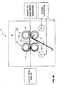
- a conventional page buffer 100 is schematically depicted and interposed between a printer 110 and a chassis module of a mailpiece inserter 112.
- the page buffer 100 communicates with a system controller 114 to monitor/track the throughput of pages 116 processed by the mailpiece inserter 112.
- the page buffer 100 receives printed pages 116 from the printer 110 and includes a plurality of sequential page stations 118a, 118b, 118c, 118d, 118e disposed along a serial feed path.
- Position sensing devices 120 are located at or along each of the page stations 118a, 118b, 118c, 118d, 118e to monitor the rate at which printed pages 116 enter or leave the page buffer 100. Further, the sensing devices 120 are operative to issue position signals 122 to the system controller 114 such that the inserter 110 may determine whether a page or sheet 116 is positioned at a particular one of the page stations 118a, 118b, 118c, 118d, 118e or whether the page station is available for receipt of another printed page 116.
- the rate of change of the position signals 122 may be used by the controller 114 to determine the throughput at which content material is processed.
- the "throughput” or “throughput rate” is the magnitude at which sheet material is processed, whether in terms of a steady number of "sheets per unit time", bundles of sheets (e.g., bundles of five (5) sheets requested every several seconds) or a non-steady flow of sheets.
- the design of a page buffer is influenced by a variety of factors including: (i) the space envelope (i.e., length and height availability) of a mailpiece (ii) the number of page stations desired/required, (iii) the travel/conveyor distance from the printer to the inserter, (iv) the processing or throughput speed of the printer as compared to the inserter (i.e., can one module print/process pages faster, slower or at the same rate as the other module), and (v) other unique requirements such as whether pages must be inverted as a result of duplex or dual-sided printing.
- the space envelope i.e., length and height availability
- the minimum conveyer or feed path length is approximately five feet (5') (1.5 m), i.e., five times the length of each station.
- the page buffer 100 described above accommodates the length of the feed path by incorporating an upper turn-around section 100T, i.e., a vertical portion extending above the printer 110.
- an upper turn-around section 100T i.e., a vertical portion extending above the printer 110.
- the design envelope of the page buffer may not facilitate or accommodate the upper turn-around section 100T, or require additional page stations, (i.e., the addition of two (2) or three (3) page stations for a total of eight (8) stations), the total length of the feed path may preclude this design option.
- the length of the conveyer can impact other design parameters such as the speed, power and acoustics required and/or generated by the page buffer.
- the conveyer speed must also increase to transport pages in the same time interval.
- the speed, power and acoustics can exceed threshold levels which place yet other limitations on the design of the page buffer.
- the throughput capacity of the printer must be compatible, or made compatible, with the throughput of the inserter.
- other factors such as the number of pages being processed at a particular point in time must be considered. For example, any time that the printer is processing pages, other pages, internal to the printer are being processed, including duplex or dual-sided pages.
- the page buffer must also accommodate or be prepared to queue pages "in process”. As printers process pages at a higher rate, i.e., process more pages on a "per unit time basis", page buffers must accommodate the additional throughput.
- Document JP 061 56 797 discloses a buffer system and a method of increasing throughput in a transport system by narrowing internal between the paper sheets. It is executed by nipping the sheets in buffer stations and thus creating looped sheets.
- a page buffer is provided for receiving and holding, in queue, pages prepared by a printer and subsequently processed by mailpiece inserter.
- the page buffer includes pairs of vertically-aligned rollers defining a plurality of page stations therebetween. Each pair of rollers is spaced-apart and defines a nip for driving the printed pages along a feed path. Furthermore, each page station is defined by and between a first pair of rollers disposed downstream of an adjacent second pair of rollers.
- a drive means is also provided for independently driving the pairs of vertically-aligned rollers. The drive means is controlled such that, in a first operating mode, the pairs cooperate to drive printed pages along the feed path.
- the drive means is controlled such that at least one of the page stations causes its respective first pair of rollers to retain and hold a leading edge portion of a printed page while the adjacent second pair drives and releases a trailing edge portion of the printed page.
- the printed page is, therefore, held within the page station such that the trailing edge droops below the feed path in a predominantly vertical orientation.
- inventive page buffer and method for controlling the same are described in the context of a mailpiece inserter system, though the inventive page buffer and control methodology may be used in combination with any sheet handling device which requires that sheet material or pages be held in a queue for subsequent processing. Further, the invention is described in the context of a DI 900 Model Mailpiece Inserter, i.e., a mailpiece creation system produced by Pitney Bowes Inc., located in Stamford, State of Connecticut, USA, though, the inventive subject matter may be employed in any mailpiece inserter.
- DI 900 Model Mailpiece Inserter i.e., a mailpiece creation system produced by Pitney Bowes Inc., located in Stamford, State of Connecticut, USA, though, the inventive subject matter may be employed in any mailpiece inserter.
- a dedicated printer 8 is integrated with the mailpiece inserter 10 and is disposed upstream of various inserter devices (also referred to as “downstream devices” when the discussion/ description is relative to the printer 8) which handle and process the mailpiece content material 12.
- inserter devices also referred to as "downstream devices” when the discussion/ description is relative to the printer 8
- the terms "mailpiece content material”, “printed pages”, “printed material”, “sheets” and /or "sheet material” will used interchangeably.
- an HP 4350 and HP 4700 model printer manufactured by Hewlett Packard (HP), is integrated with the mailpiece inserter 10.
- the HP 4350 printer system is a black & white printer having an output rate of approximately fifty-five (55) pages per minute.
- the HP 4700 is a color printer having an output rate of approximately thirty (30) pages per minute.
- a page buffer 20 is disposed downstream of the printer 8 and, inter alia, functions to accept, temporarily hold, and subsequently deliver printed pages 12 to the mailpiece inserter 10 for processing. More specifically, the page buffer 20 receives printed pages 12 from the printer 8 and includes a plurality of page stations 30 (discussed in greater detail hereinafter) disposed along the feed path i.e., between the printer 8 and the mailpiece inserter 10. The page stations 30 receive and hold content material 12 in a queue station (one page in each station) until a request is made by the inserter 10 that one or more printed pages 12 are needed, i.e., are to be released.
- the page buffer 20 includes position sensing devices, (not shown) located at or along each of the page stations 30, to monitor the rate that printed pages enter or leave the page buffer 20. Furthermore, the sensing devices are operative to issue position signals 32 to a system controller 34 such that the inserter 10 may determine whether a page or sheet 12 is positioned at a particular one of the page stations 30. In the described embodiment, the sensing devices are photocells, though any position sensor may be employed.
- the rate of change of the position signals 32 may be used by the controller 34 to determine the throughput of the inserter 10.
- the "throughput” or “throughput rate” is the magnitude at which sheet material 12 is processed, whether in terms of a steady number of "sheets per unit time", bundles of sheets (e.g., bundles of five (5) or ten (10) sheets requested every several seconds) or a non-steady flow of sheets.
- downstream device While in the described embodiment the initial/first downstream device is a page buffer 20, it should be appreciated that any downstream device may be adapted to issue a throughput signal indicative of a processing rate.
- downstream devices may additionally, or alternatively, include an accumulator 35, a pre-fold accumulator 36, a folder 37, an envelop inserter 38, and/or a sealer 39.
- the system controller 34 monitors the throughput data and issues command signals 40 indicative of the number of pages 12 to be printed by the integrated printer 8. More specifically, the command signals 40 are indicative of a specific page number at which to begin printing along with the number of pages 12 to follow. For example, the controller 34 may issue a command signal 40 which requests the printer 8 to generate page number thirty (Page # 30) plus five (5) additional pages of data. Before this request is issued to the printer 8 (in the more conventional sense), the controller 34 issues the command through a page-based language monitor 42. In the preferred embodiment, the system controller 34 generally issues command signals 40 to print between three (3) and seven (7) pages with each request, though several command signals 40 may be generated within a very short period of time.
- the mailpiece inserter 10 further includes a User Interface Module (UIM) 44 interposing the page buffer 20 and the system controller 34.
- the UIM 44 is responsive to the position signals 32 of the page buffer 20 for determining when additional pages, sheets of content material 12, can be accepted by the page buffer 20.
- the UIM 44 is operative to issue request signals 48 to the system controller 34, i.e., the request signals 48 to print additional pages 12.
- conversion of the position signals 32 to command signals 40 may be performed by either the system controller 34 or by the UIM 44, depending upon where the program logic/intelligence is located.
- the controller 34 may have received a message that the print job, i.e., determined at the User PC 14, is complete. Consequently, in this instance, the controller 34 will not forward a command signal 40 to the language monitor 42 for issuance to the printer 8.
- the page-based language monitor 42 receives print stream data from a page-based print processor 50 and is interposed between the system controller 34 and the dedicated printer 8.
- the LM 42 is the gate-keeper of data communicated to the printer 8 from the controller 34. More specifically, the LM 42 retains material content data, including an object-data dictionary, for each page of material content and triggers the printer 8 to generate a particular page (i.e., page number) along with N number of additional pages. While this request to print is made by the system controller 34, the LM 42 contains the active program code which intercepts the print stream data, i.e., the print control language (PCL), from the printer driver to throttle the rate at which content material 12 is generated by the printer 8.
- PCL print control language
- the page-based LM 42 is operative to vary the flow of print stream data to the printer 8 and vary the production rate of mailpiece content material.
- the LM 42 includes a buffer file capable of storing 300 MB (300,000,000 bytes) of data and, accordingly, the buffer file is capable of storing multiple pages of data, including duplex pages.
- a "page" of data includes all data which may be found on a one- or two-sided sheet of paper.
- the language monitor 42 and print processor 50 issue a print command signal 52 to throttle/control the output of the printer 8 in order to be consistent with or match the throughput of the mailpiece inserter 10.
- a print command signal 52 to throttle/control the output of the printer 8 in order to be consistent with or match the throughput of the mailpiece inserter 10.
- additional or more frequent requests for additional printed pages 12 can be made.
- requests can be made for a fewer number of printed pages or at less frequent intervals to prevent an overload condition or too many sheets from being printed over a prescribed period of time.
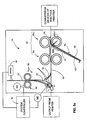
- the page buffer 20 includes pairs of vertically-aligned rollers 60 (hereinafter referred to as “pairs of rollers” or simply “pairs”) which define a plurality of page stations 30 therebetween.
- vertical-aligned means that the rotational axes 62A of each pair are substantially vertically aligned. While the nip between the pairs 60 drives sheet material along a substantially horizontal feed path FP, the feed path FP may be inclined or declined depending upon the relative height between the printer and mailpiece inserter.
- eleven (11) pairs of rollers 60 1 , 60 2 ...60 11 are depicted defining a total of ten (10) page stations 30 1 , 30 2 ...30 10 therebetween, though the page buffer 20 may contain as few as three (3) page stations or as many as twenty (20) depending, inter alia, upon the throughput capacity of the printer.
- the page stations 30 lie between adjacent pairs of rollers 60, i.e., between, for example, an upstream pair 60 2 and a downstream pair 60 3 , the page stations 30 also lie below the feed path FP in a predominantly vertical orientation.
- "predominantly vertical orientation” means that that page stations extend vertically downward by a dimension less than about the length of a printed page.
- the horizontal distance or distance from one page station to an adjacent station, e.g., from 30 1 to 30 2 should preferably be less than about one-half the length of the printed page.
- the page stations 30 are essentially face-to-face. The significance of the spatial orientation and the method for loading and unloading the page stations will become clear in subsequent paragraphs.
- FIGs. 4a , 4b and 4c depict the operation and control of two adjacent pairs of rollers 60 1 , 60 2 to capture and temporarily hold or "buffer" a printed page 12 in a single page station 30 1 .
- Any of the adjacent pairs 60 could be used for illustration purposes, though it should be appreciated that the page stations 30 will generally be loaded from a downstream page station to an upstream page station. For example, pages will be stored or buffered in a sequence beginning with page station 30 10 (see Fig. 3 ) and continue, as buffer stations are needed, until page station 30 1 is occupied. Furthermore, the page stations 30 will be unloaded on a "first in first out” (FIFO) basis. Hence, if pages 12 are buffered so as to fill stations 30 10 through 30 4 , then pages will be released or unbuffered from page station 30 10 to page station 30 4 until the page buffer is empty and can, once again, buffer pages.
- FIFO first in first out
- the page buffer 20 can be operated in various operational modes and controlled by driving the pairs of rollers 60 1 , 60 2 independently.
- each of the pairs 60 1 , 60 2 is driven by a respective drive motor M which is responsive to signals received from the system controller 34.
- the system controller 34 drives the motors M such that the downstream pair 60 2 retains and holds a leading edge portion 12L of a printed page 12 while upstream pair 60 1 holds the remaining portion of the printed page 12. Consequently, both motors M are driven in unison to cause the printed page 12 to traverse from the nip of one pair 60 to the nip of the adjacent pair 60 2 .
- the controller 34 holds the downstream pair of rollers 60 2 stationary, i.e., issues a stop signal to the motor M, while driving the upstream pair of rollers 60 1 .
- the leading edge portion 12L is captured within the nip of the downstream pair of rollers 60 2 while the trailing edge portion 12T continues to be driven by the upstream pair 60 1 .
- the printed page 12 begins to bend and/or buckle about its midportion 12M.
- an arcuate guide 70 having a downwardly projecting concave surface 70CS may be interposed between the pairs 60 1 , 60 2 . More specifically, the concave surface 70CS is spatially positioned to intersect or interrupt the feed path FP of the printed page 12 so as to guide the midportion 12M thereof in the desired downward direction.
- the printed page 12 is buffered or stored within the page station 30 1 . While buffered, the leading edge portion 12L is captured within the nip of the downstream pair of rollers 60 2 while the upstream pair 60 1 has driven and released the trailing edge portion 12T of the page 12.
- the support tray 80 may be coupled to any fixed or stationary structure of the page buffer 20 or to the rotational axis 62A-1 supporting the lower roller of the pair 60 2 .
- the tray 80 may additionally provide an inclined surface 80N for guiding the leading edge 12L of the printed page 12. That is, the inclined surface 80N may be spatially and angularly adapted to guide the leading edge 12L into the nip of the downstream pair of rollers 60 2 . Furthermore, the upward inclination of the guide surface 80N may offset any downward inclination of the leading edge caused by the concave surface 70CS of the arcuate guide 70.
- a sheet handling mechanism 90 is incorporated upstream of the vertically oriented pairs 60 1 to invert printed pages 12 from a face-up to face down orientation.
- the sheet handling or inversion mechanism 90 includes a movable or positionable diverter 92 which may be rotated counterclockwise in the direction of arrow D1 from a ready position (shown in dashed lines) to an operational position (shown in solid lines).
- a ready position shown in dashed lines
- an operational position shown in solid lines
- the ready position printed pages 12 by-pass the inversion mechanism 90 and pass directly to the vertically-aligned pairs of rollers 60.
- the movable diverter 92 interposes the feed path FP to direct printed pages 12 from the printer output to a pair of horizontally-aligned rollers 94.
- the horizontally-aligned rollers 94 may extend above or below the feed path FP and are operative to accept, momentarily hold, and return the printed pages to the original or primary feed path. More specifically, the rollers 94 rotate in a first direction to accept a printed page.
- the movable diverter rotates in a clockwise direction D2 to urge the trailing edge of the printed page toward a second or return diverter 98.
- the return diverter 98 is a fixed position guide, though it too can be movable or positionable.
- the pair of horizontal rollers 94 returns the printed page to the primary feed path FP between the vertically-aligned pairs of rollers 60.
- the printed page 12 is now inverted or face-down relative to its original face-up orientation.
- the system controller 34 issues and receives signals from the various driven components.
- the controller 34 may be operative to drive a rotary actuator MD connected to the movable diverter 92, control a drive motor M2 associated with the horizontally aligned rollers 94 and receive/process signals from the leading edge sensor 96.
- the page buffer 20 may be adapted to fill, hold and release pages 12 within select page stations 30.
- the system controller 34 has filled all of the page stations 30 with the exception of page stations 30 4 and 30 7 . Determining whether a page station 30 is filled or void will depend upon a variety of factors. However, one example may involve whether a mailpiece has one or several printed sheets. Using this example, a first mailpiece may have three (3) sheets of printed content material and may have been buffered in stations 30 1 , 30 2 , and 30 3 . A second mailpiece may have two (2) sheets of printed content material and may have been buffered in stations 30 5 , and 30 6 .
- a third mailpiece may have one (1) sheet of printed content material and may have been buffered in station 30 8 .
- Fourth and fifth mailpieces may also each have a single sheet which may have been buffered in stations 30 9 and 30 10 , respectively.
- Stations 30 4 and 30 7 may be been left void to provide spacing between the buffered sheets 12.
- the system controller 34 may drive the individual motors M to first remove, in sequential order, the pages 12 in page stations 30 8 , 30 9 and 30 10 to fulfill the fabrication of three individual mailpieces. Thereafter, the system controller 34 may drive the motors associated with stations 30 5 , 30 6 , though, the printed page in station 30 5 may be released first to shingle with the leading edge of the page in station 30 6 , thereby creating a two sheet collation 12C2. The system controller 34 then drives all motors M in connection with stations 30 6 , 30 7 , 30 8 , 30 9 , and 30 10 for conveying the two sheet collation 12C2 along the feed path FP.
- the system controller 34 then drives all motors M in connection with stations 30 1 , 30 2 , 30 3 , releasing the pages in reverse order i.e., stations 30 3 , 30 2 , and 30 1 , to shingle the pages into a three sheet collation 12C3. Finally, all of the drive motors M are activated to convey the final collated group 12C3 along the feed path FP. Accordingly, the page buffer 20 can be controlled in a variety of ways to buffer and release pages 12, individually or as a group to increase throughput, or accelerate collation in the accumulator module 35 of the mailpiece inserter 10.
- the page buffer 20 provides multiple page stations within a low-profile, space-efficient design envelope.
- the embodiment of the present invention employs vertically-oriented face-to-face pages stations. These vertically-oriented page stations provide a unique opportunity to minimize the overall length requirements of the page buffer 20.
- the page buffer 20 can be operated efficiently with or without the requirement to buffer pages. That is, the closely-spaced rollers and nips allow the page buffer to operate efficiently as a linear transport, but also provide the opportunity to buffer the printed pages as required.
- the relatively short distance between the input and output of the page buffer 20 reduces the speed and, consequently, the noise, generated by the driving motors, i.e., the motors which drive the transport and buffering rollers 60. Furthermore, such reduced speed requirements translate into reduced power requirements.
- the page buffer 20 provides other operational modes which reduce complexity and facilitate throughput.
- the vertically-oriented pairs 60 simplify assembly and provide commonality of components. As such, fabrication and maintenance costs are minimized.
- the linear arrangement of rolling elements facilitates the ability to invert sheets from a face-up to face down orientation.
- such linear arrangement enables the grouping and/or shingling of sheets 12 internally of the page buffer 20 to transport a collation of sheets 12 along the feed path. Such grouping of printed pages enables higher system throughput by transporting a plurality of sheets while minimizing the spacing therebetween.
Landscapes
- Engineering & Computer Science (AREA)
- Mechanical Engineering (AREA)
- Separation, Sorting, Adjustment, Or Bending Of Sheets To Be Conveyed (AREA)
- Delivering By Means Of Belts And Rollers (AREA)
Claims (9)
- Seitenzwischenaufnahme (20) zum Halten von Seiten in einer Schlange, die von einem Drucker (8) erstellt wurden und anschließend von einer Poststückeinsetzvorrichtung (10) verarbeitet werden, umfassend:Paare (601-6011) vertikal ausgerichteter Walzen (60), die mehrere Seitenstationen (30) zwischen ihnen definieren, wobei jedes Paar beabstandet ist und einen Spalt zum Antreiben der gedruckten Seiten von einem Paar zu einem anderen Paar entlang einem Vorschubpfad (FP) definiert, wobei jede Seitenstation von und zwischen einem ersten Paar von Walzen definiert ist, das einem benachbarten zweiten Paar nachgelagert ist;ein Antriebsmittel (M) zum unabhängigen Antreiben der Paare vertikal ausgerichteter Walzen;gekennzeichnet durch eine Steuerung (34), die zum derartigen Steuern des Antriebsmittels (M) betriebsbereit ist, dass in einem ersten Betriebsmodus die Paare zum Antreiben gedruckter Seiten entlang des Vorschubpfads (FP) zusammenwirken und in einem zweiten Betriebsmodus mindestens eine der Seitenstationen (30) das erste Paar veranlasst, einen führenden Randabschnitt einer gedruckten Seite zu halten, während das zweite Paar einen nachlaufenden Randabschnitt der gedruckten Seite antreibt und freigibt, wobei die gedruckte Seite in der Seitenstation so aufgenommen wird, dass der nachlaufende Rand in einer vorwiegend vertikalen Ausrichtung unter den Vorschubpfad herunterhängt.
- Seitenzwischenaufnahme nach Anspruch 1, wobei die Seitenstationen (30) paarweise von einer vorgelagerten Station (301) nahe dem Drucker zu einer nachgelagerten Station (3010), die der Poststückeinsetzvorrichtung am nächsten ist, angeordnet sind, und wobei die Steuerung (34) derart betriebsbereit ist, dass Seitenstationen (30) der Reihe nach von den nachgelagerten Seitenstationen zu dem vorgelagerten Seitenstationen gefüllt werden.
- Seitenzwischenaufnahme nach Anspruch 1 oder 2, wobei die Seiten an jeder Seite bedruckt sind, und des Weiteren umfassend:eine Wendevorrichtung, die den vertikal ausgerichteten Walzen vorgelagert angeordnet und betriebsbereit ist, um die gedruckte Seite mit nach oben weisender Seite beim Verlassen des Druckers zu einer nach unten weisenden Seite beim Eintritt in die vertikal ausgerichteten Walzen zu wenden.
- Seitenzwischenaufnahme nach Anspruch 3, wobei die Wendevorrichtung enthält: mindestens ein Paar horizontal ausgerichteter Walzen (94), wobei die horizontal ausgerichteten Walzen den vertikal ausgerichteten Walzen vorgelagert und zu einer Seite des Vorschubpfades angeordnet sind, wobei die horizontal ausgerichteten Walzen einen Spalt zwischen ihnen definieren, um die gedruckten Seiten aufzunehmen und zu transportieren;
eine Lenkvorrichtung (92), die in einer Bereitschaftsposition, in der gedruckte Seiten vom Drucker zu den vertikal ausgerichteten Walzen laufen können, und in einer betriebsbereiten Position, in der bedruckte Seiten vom Drucker zum Spalt der horizontal ausgerichteten Walzen laufen können, positionierbar ist; und
eine zweite Lenkvorrichtung (98), die zum Lenken bedruckter Seiten von dem Spalt der horizontal ausgerichteten Walzen zu den vertikal ausgerichteten Walzen betriebsbereit ist. - Seitenzwischenaufnahme nach einem der vorangehenden Ansprüche, des Weiteren umfassend eine Führungsstruktur (301-3010) zum Führen des führenden Randes einer gedruckten Seite in den Spalt des ersten Walzenpaares.
- Seitenzwischenaufnahme nach einem der vorangehenden Ansprüche, des Weiteren umfassend eine Trägerschale (80) nahe dem ersten Walzenpaar jeder Seitenstation und betriebsbereit, um das nachlaufende Ende einer gedruckten Seite zu stützen.
- Seitenzwischenaufnahme nach Anspruch 6, des Weiteren umfassend die Trägerschale (80), die des Weiteren eine Führungsfläche definiert, um den führenden Rand einer gedruckten Seite in den Spalt des ersten Walzenpaars zu führen.
- Seitenzwischenaufnahme nach einem der vorangehenden Ansprüche, des Weiteren umfassend eine bogenförmige Führungsstruktur (70), die zwischen dem ersten und zweiten Walzenpaar jeder Seitenstation angeordnet und betriebsbereit ist, um die gedruckte Seite in eine Abwärtsrichtung zu biegen.
- Seitenzwischenaufnahme nach einem der vorangehenden Ansprüche, wobei gedruckte Seiten von den Seitenstationen freigegeben werden können, wenn die Seitenzwischenaufnahme ein Seitenanfragesignal von der Poststückeinsetzvorrichtung empfängt, und wobei die Steuerung betriebsbereit ist, das Antriebsmittel derart zu steuern, dass in einem dritten Betriebsmodus vorgelagerte Seitenstationen veranlasst werden, gedruckte Seiten freizugeben, so dass die gedruckten Seiten schindelförmig angeordnet und als Gruppe zur Poststückeinsetzvorrichtung transportiert werden.
Applications Claiming Priority (1)
| Application Number | Priority Date | Filing Date | Title |
|---|---|---|---|
| US11/846,741 US7866661B2 (en) | 2007-08-29 | 2007-08-29 | Sheet/page buffer for sheet handling apparatus |
Publications (3)
| Publication Number | Publication Date |
|---|---|
| EP2030930A2 EP2030930A2 (de) | 2009-03-04 |
| EP2030930A3 EP2030930A3 (de) | 2011-11-09 |
| EP2030930B1 true EP2030930B1 (de) | 2013-06-05 |
Family
ID=40091912
Family Applications (1)
| Application Number | Title | Priority Date | Filing Date |
|---|---|---|---|
| EP08014767.1A Ceased EP2030930B1 (de) | 2007-08-29 | 2008-08-20 | Blatt-/Seitenzwischenspeicher für Blatthandhabungsvorrichtung |
Country Status (2)
| Country | Link |
|---|---|
| US (1) | US7866661B2 (de) |
| EP (1) | EP2030930B1 (de) |
Families Citing this family (2)
| Publication number | Priority date | Publication date | Assignee | Title |
|---|---|---|---|---|
| JP4557052B2 (ja) * | 2008-06-18 | 2010-10-06 | コニカミノルタビジネステクノロジーズ株式会社 | 用紙搬送中継ユニット及び画像形成システム |
| JP6746326B2 (ja) * | 2016-02-19 | 2020-08-26 | キヤノン株式会社 | 印刷データの解釈を複数の解釈手段で行う印刷装置、印刷方法、プログラム |
Family Cites Families (15)
| Publication number | Priority date | Publication date | Assignee | Title |
|---|---|---|---|---|
| JPS5820497A (ja) * | 1981-07-31 | 1983-02-05 | 株式会社東芝 | 印字装置 |
| JPS62148297A (ja) * | 1985-12-20 | 1987-07-02 | エヌ・シー・アール・インターナショナル・インコーポレイテッド | 冊子類の頁めくり装置 |
| US4916493A (en) * | 1989-08-24 | 1990-04-10 | Xerox Corporation | Exit roller reversal gate for duplex printing |
| US5183347A (en) * | 1989-12-15 | 1993-02-02 | Kabushiki Kaisha Toshiba | Apparatus for printing images on booklets |
| DE4028094C1 (de) * | 1990-09-05 | 1992-04-02 | Du Pont De Nemours (Deutschland) Gmbh, 6380 Bad Homburg, De | |
| JPH06156797A (ja) * | 1992-11-18 | 1994-06-03 | Fuji Xerox Co Ltd | 画像形成装置の用紙搬送装置 |
| FR2700527B1 (fr) * | 1993-01-18 | 1995-04-07 | Bertin & Cie | Dispositif de stockage temporaire d'objets plats. |
| US5303017A (en) * | 1993-05-07 | 1994-04-12 | Xerox Corporation | Print skip avoidance for on-line compiling |
| EP0639521B1 (de) * | 1993-08-16 | 2000-03-01 | Agfa Corporation | Verfahren und Apparat zum Zwischenspeichern von Medien |
| US6186496B1 (en) * | 1998-08-31 | 2001-02-13 | Xerox Corporation | Optimized passive gate inverter |
| US6976673B2 (en) * | 2003-04-21 | 2005-12-20 | Hewlett-Packard Development Company, L.P. | System and method for flipping a media sheet |
| US20040251605A1 (en) * | 2003-06-13 | 2004-12-16 | Elton Hsieh | Correspondence collator and multi-sheet folding device |
| US20050017438A1 (en) * | 2003-06-30 | 2005-01-27 | Pitney Bowes Incorporated | Apparatus and method for accumulating sheets |
| DE10351305A1 (de) * | 2003-10-31 | 2005-05-25 | Man Roland Druckmaschinen Ag | Kombinierte Druckmaschine |
| US7706737B2 (en) * | 2005-11-30 | 2010-04-27 | Xerox Corporation | Mixed output printing system |
-
2007
- 2007-08-29 US US11/846,741 patent/US7866661B2/en not_active Expired - Fee Related
-
2008
- 2008-08-20 EP EP08014767.1A patent/EP2030930B1/de not_active Ceased
Also Published As
| Publication number | Publication date |
|---|---|
| EP2030930A3 (de) | 2011-11-09 |
| US20090057974A1 (en) | 2009-03-05 |
| EP2030930A2 (de) | 2009-03-04 |
| US7866661B2 (en) | 2011-01-11 |
Similar Documents
| Publication | Publication Date | Title |
|---|---|---|
| KR100255580B1 (ko) | 컴퓨터 소프트웨어에 의해 제어되는 우편 발송 장치 | |
| EP2213602A2 (de) | Postkuvertierer für eine einseitige Bedienung und Eingabefördermodul dafür | |
| EP1953705B1 (de) | Verfahren und System zur Fehlerreduzierung beim Verarbeiten von Druckstromdaten | |
| EP2030930B1 (de) | Blatt-/Seitenzwischenspeicher für Blatthandhabungsvorrichtung | |
| US7845639B2 (en) | Multi-function low profile print interface for a sheet handling device | |
| EP0448271A1 (de) | Mechanismus und Verfahren zum Falten und Verschliessen der oberen und der Seitenlappen eines Formularbriefes | |
| US6687569B1 (en) | Configurable multi-station buffer transport for an inserter system | |
| EP2714422B1 (de) | Maschinenzwischenpuffer für ein system zur herstellung von briefsendungen | |
| US8544837B2 (en) | Vacuum roller assembly | |
| US6805346B2 (en) | Bottom stacking apparatus for stacking mailpieces | |
| US8215629B2 (en) | System and method for producing and arranging sheet material for use in a mailpiece inserter | |
| US6776406B2 (en) | Feeder and separator for separating and moving sheets from a stack of sheets | |
| US8746688B2 (en) | Accumulator for a sheet handling system | |
| US8540226B2 (en) | System and method for minimizing the conveyance feed path of a sheet material handling system | |
| EP1952996B1 (de) | Multifunktionelle Niedrigprofil-Druckschnittstelle für eine Papierbehandlungsvorrichtung | |
| EP1952995B1 (de) | Druckschnittstellensystem für eine Papierbehandlungsvorrichtung | |
| US8327993B2 (en) | Safety device for a linear actuation system | |
| US12211355B2 (en) | Card processing and attaching system |
Legal Events
| Date | Code | Title | Description |
|---|---|---|---|
| PUAI | Public reference made under article 153(3) epc to a published international application that has entered the european phase |
Free format text: ORIGINAL CODE: 0009012 |
|
| AK | Designated contracting states |
Kind code of ref document: A2 Designated state(s): AT BE BG CH CY CZ DE DK EE ES FI FR GB GR HR HU IE IS IT LI LT LU LV MC MT NL NO PL PT RO SE SI SK TR |
|
| AX | Request for extension of the european patent |
Extension state: AL BA MK RS |
|
| PUAL | Search report despatched |
Free format text: ORIGINAL CODE: 0009013 |
|
| AK | Designated contracting states |
Kind code of ref document: A3 Designated state(s): AT BE BG CH CY CZ DE DK EE ES FI FR GB GR HR HU IE IS IT LI LT LU LV MC MT NL NO PL PT RO SE SI SK TR |
|
| AX | Request for extension of the european patent |
Extension state: AL BA MK RS |
|
| RIC1 | Information provided on ipc code assigned before grant |
Ipc: B65H 29/12 20060101AFI20110930BHEP Ipc: B65H 39/10 20060101ALI20110930BHEP |
|
| 17P | Request for examination filed |
Effective date: 20120125 |
|
| AKX | Designation fees paid |
Designated state(s): DE FR GB |
|
| GRAP | Despatch of communication of intention to grant a patent |
Free format text: ORIGINAL CODE: EPIDOSNIGR1 |
|
| GRAS | Grant fee paid |
Free format text: ORIGINAL CODE: EPIDOSNIGR3 |
|
| GRAA | (expected) grant |
Free format text: ORIGINAL CODE: 0009210 |
|
| AK | Designated contracting states |
Kind code of ref document: B1 Designated state(s): DE FR GB |
|
| REG | Reference to a national code |
Ref country code: GB Ref legal event code: FG4D |
|
| REG | Reference to a national code |
Ref country code: DE Ref legal event code: R096 Ref document number: 602008025104 Country of ref document: DE Effective date: 20130801 |
|
| PLBE | No opposition filed within time limit |
Free format text: ORIGINAL CODE: 0009261 |
|
| STAA | Information on the status of an ep patent application or granted ep patent |
Free format text: STATUS: NO OPPOSITION FILED WITHIN TIME LIMIT |
|
| 26N | No opposition filed |
Effective date: 20140306 |
|
| REG | Reference to a national code |
Ref country code: DE Ref legal event code: R097 Ref document number: 602008025104 Country of ref document: DE Effective date: 20140306 |
|
| REG | Reference to a national code |
Ref country code: FR Ref legal event code: PLFP Year of fee payment: 9 |
|
| REG | Reference to a national code |
Ref country code: FR Ref legal event code: PLFP Year of fee payment: 10 |
|
| PGFP | Annual fee paid to national office [announced via postgrant information from national office to epo] |
Ref country code: GB Payment date: 20170829 Year of fee payment: 10 Ref country code: DE Payment date: 20170829 Year of fee payment: 10 Ref country code: FR Payment date: 20170825 Year of fee payment: 10 |
|
| REG | Reference to a national code |
Ref country code: DE Ref legal event code: R119 Ref document number: 602008025104 Country of ref document: DE |
|
| GBPC | Gb: european patent ceased through non-payment of renewal fee |
Effective date: 20180820 |
|
| PG25 | Lapsed in a contracting state [announced via postgrant information from national office to epo] |
Ref country code: DE Free format text: LAPSE BECAUSE OF NON-PAYMENT OF DUE FEES Effective date: 20190301 |
|
| PG25 | Lapsed in a contracting state [announced via postgrant information from national office to epo] |
Ref country code: FR Free format text: LAPSE BECAUSE OF NON-PAYMENT OF DUE FEES Effective date: 20180831 |
|
| PG25 | Lapsed in a contracting state [announced via postgrant information from national office to epo] |
Ref country code: GB Free format text: LAPSE BECAUSE OF NON-PAYMENT OF DUE FEES Effective date: 20180820 |