EP2031415A1 - Réseau d'antennes commutable pour l'estimation de la direction d'incidence d'un signal reçu - Google Patents
Réseau d'antennes commutable pour l'estimation de la direction d'incidence d'un signal reçu Download PDFInfo
- Publication number
- EP2031415A1 EP2031415A1 EP08021230A EP08021230A EP2031415A1 EP 2031415 A1 EP2031415 A1 EP 2031415A1 EP 08021230 A EP08021230 A EP 08021230A EP 08021230 A EP08021230 A EP 08021230A EP 2031415 A1 EP2031415 A1 EP 2031415A1
- Authority
- EP
- European Patent Office
- Prior art keywords
- arrival
- estimating
- antenna
- antenna elements
- elements
- Prior art date
- Legal status (The legal status is an assumption and is not a legal conclusion. Google has not performed a legal analysis and makes no representation as to the accuracy of the status listed.)
- Granted
Links
Images


Classifications
-
- G—PHYSICS
- G01—MEASURING; TESTING
- G01S—RADIO DIRECTION-FINDING; RADIO NAVIGATION; DETERMINING DISTANCE OR VELOCITY BY USE OF RADIO WAVES; LOCATING OR PRESENCE-DETECTING BY USE OF THE REFLECTION OR RERADIATION OF RADIO WAVES; ANALOGOUS ARRANGEMENTS USING OTHER WAVES
- G01S13/00—Systems using the reflection or reradiation of radio waves, e.g. radar systems; Analogous systems using reflection or reradiation of waves whose nature or wavelength is irrelevant or unspecified
- G01S13/02—Systems using reflection of radio waves, e.g. primary radar systems; Analogous systems
- G01S13/06—Systems determining position data of a target
- G01S13/42—Simultaneous measurement of distance and other co-ordinates
- G01S13/424—Stacked beam radar
-
- G—PHYSICS
- G01—MEASURING; TESTING
- G01S—RADIO DIRECTION-FINDING; RADIO NAVIGATION; DETERMINING DISTANCE OR VELOCITY BY USE OF RADIO WAVES; LOCATING OR PRESENCE-DETECTING BY USE OF THE REFLECTION OR RERADIATION OF RADIO WAVES; ANALOGOUS ARRANGEMENTS USING OTHER WAVES
- G01S7/00—Details of systems according to groups G01S13/00, G01S15/00, G01S17/00
- G01S7/02—Details of systems according to groups G01S13/00, G01S15/00, G01S17/00 of systems according to group G01S13/00
- G01S7/03—Details of HF subsystems specially adapted therefor, e.g. common to transmitter and receiver
- G01S7/032—Constructional details for solid-state radar subsystems
-
- G—PHYSICS
- G01—MEASURING; TESTING
- G01S—RADIO DIRECTION-FINDING; RADIO NAVIGATION; DETERMINING DISTANCE OR VELOCITY BY USE OF RADIO WAVES; LOCATING OR PRESENCE-DETECTING BY USE OF THE REFLECTION OR RERADIATION OF RADIO WAVES; ANALOGOUS ARRANGEMENTS USING OTHER WAVES
- G01S7/00—Details of systems according to groups G01S13/00, G01S15/00, G01S17/00
- G01S7/02—Details of systems according to groups G01S13/00, G01S15/00, G01S17/00 of systems according to group G01S13/00
- G01S7/35—Details of non-pulse systems
-
- H—ELECTRICITY
- H01—ELECTRIC ELEMENTS
- H01Q—ANTENNAS, i.e. RADIO AERIALS
- H01Q3/00—Arrangements for changing or varying the orientation or the shape of the directional pattern of the waves radiated from an antenna or antenna system
- H01Q3/24—Arrangements for changing or varying the orientation or the shape of the directional pattern of the waves radiated from an antenna or antenna system varying the orientation by switching energy from one active radiating element to another, e.g. for beam switching
-
- H—ELECTRICITY
- H01—ELECTRIC ELEMENTS
- H01Q—ANTENNAS, i.e. RADIO AERIALS
- H01Q3/00—Arrangements for changing or varying the orientation or the shape of the directional pattern of the waves radiated from an antenna or antenna system
- H01Q3/26—Arrangements for changing or varying the orientation or the shape of the directional pattern of the waves radiated from an antenna or antenna system varying the relative phase or relative amplitude of energisation between two or more active radiating elements; varying the distribution of energy across a radiating aperture
-
- G—PHYSICS
- G01—MEASURING; TESTING
- G01S—RADIO DIRECTION-FINDING; RADIO NAVIGATION; DETERMINING DISTANCE OR VELOCITY BY USE OF RADIO WAVES; LOCATING OR PRESENCE-DETECTING BY USE OF THE REFLECTION OR RERADIATION OF RADIO WAVES; ANALOGOUS ARRANGEMENTS USING OTHER WAVES
- G01S13/00—Systems using the reflection or reradiation of radio waves, e.g. radar systems; Analogous systems using reflection or reradiation of waves whose nature or wavelength is irrelevant or unspecified
- G01S13/003—Bistatic radar systems; Multistatic radar systems
-
- G—PHYSICS
- G01—MEASURING; TESTING
- G01S—RADIO DIRECTION-FINDING; RADIO NAVIGATION; DETERMINING DISTANCE OR VELOCITY BY USE OF RADIO WAVES; LOCATING OR PRESENCE-DETECTING BY USE OF THE REFLECTION OR RERADIATION OF RADIO WAVES; ANALOGOUS ARRANGEMENTS USING OTHER WAVES
- G01S13/00—Systems using the reflection or reradiation of radio waves, e.g. radar systems; Analogous systems using reflection or reradiation of waves whose nature or wavelength is irrelevant or unspecified
- G01S13/02—Systems using reflection of radio waves, e.g. primary radar systems; Analogous systems
- G01S13/06—Systems determining position data of a target
- G01S13/08—Systems for measuring distance only
- G01S13/32—Systems for measuring distance only using transmission of continuous waves, whether amplitude-, frequency-, or phase-modulated, or unmodulated
- G01S13/34—Systems for measuring distance only using transmission of continuous waves, whether amplitude-, frequency-, or phase-modulated, or unmodulated using transmission of continuous, frequency-modulated waves while heterodyning the received signal, or a signal derived therefrom, with a locally-generated signal related to the contemporaneously transmitted signal
- G01S13/345—Systems for measuring distance only using transmission of continuous waves, whether amplitude-, frequency-, or phase-modulated, or unmodulated using transmission of continuous, frequency-modulated waves while heterodyning the received signal, or a signal derived therefrom, with a locally-generated signal related to the contemporaneously transmitted signal using triangular modulation
-
- G—PHYSICS
- G01—MEASURING; TESTING
- G01S—RADIO DIRECTION-FINDING; RADIO NAVIGATION; DETERMINING DISTANCE OR VELOCITY BY USE OF RADIO WAVES; LOCATING OR PRESENCE-DETECTING BY USE OF THE REFLECTION OR RERADIATION OF RADIO WAVES; ANALOGOUS ARRANGEMENTS USING OTHER WAVES
- G01S13/00—Systems using the reflection or reradiation of radio waves, e.g. radar systems; Analogous systems using reflection or reradiation of waves whose nature or wavelength is irrelevant or unspecified
- G01S13/88—Radar or analogous systems specially adapted for specific applications
- G01S13/93—Radar or analogous systems specially adapted for specific applications for anti-collision purposes
- G01S13/931—Radar or analogous systems specially adapted for specific applications for anti-collision purposes of land vehicles
-
- G—PHYSICS
- G01—MEASURING; TESTING
- G01S—RADIO DIRECTION-FINDING; RADIO NAVIGATION; DETERMINING DISTANCE OR VELOCITY BY USE OF RADIO WAVES; LOCATING OR PRESENCE-DETECTING BY USE OF THE REFLECTION OR RERADIATION OF RADIO WAVES; ANALOGOUS ARRANGEMENTS USING OTHER WAVES
- G01S7/00—Details of systems according to groups G01S13/00, G01S15/00, G01S17/00
- G01S7/02—Details of systems according to groups G01S13/00, G01S15/00, G01S17/00 of systems according to group G01S13/00
- G01S7/03—Details of HF subsystems specially adapted therefor, e.g. common to transmitter and receiver
- G01S7/034—Duplexers
-
- G—PHYSICS
- G01—MEASURING; TESTING
- G01S—RADIO DIRECTION-FINDING; RADIO NAVIGATION; DETERMINING DISTANCE OR VELOCITY BY USE OF RADIO WAVES; LOCATING OR PRESENCE-DETECTING BY USE OF THE REFLECTION OR RERADIATION OF RADIO WAVES; ANALOGOUS ARRANGEMENTS USING OTHER WAVES
- G01S7/00—Details of systems according to groups G01S13/00, G01S15/00, G01S17/00
- G01S7/02—Details of systems according to groups G01S13/00, G01S15/00, G01S17/00 of systems according to group G01S13/00
- G01S7/40—Means for monitoring or calibrating
- G01S7/4004—Means for monitoring or calibrating of parts of a radar system
- G01S7/4026—Antenna boresight
-
- G—PHYSICS
- G01—MEASURING; TESTING
- G01S—RADIO DIRECTION-FINDING; RADIO NAVIGATION; DETERMINING DISTANCE OR VELOCITY BY USE OF RADIO WAVES; LOCATING OR PRESENCE-DETECTING BY USE OF THE REFLECTION OR RERADIATION OF RADIO WAVES; ANALOGOUS ARRANGEMENTS USING OTHER WAVES
- G01S7/00—Details of systems according to groups G01S13/00, G01S15/00, G01S17/00
- G01S7/48—Details of systems according to groups G01S13/00, G01S15/00, G01S17/00 of systems according to group G01S17/00
- G01S7/497—Means for monitoring or calibrating
- G01S7/4972—Alignment of sensor
Definitions
- the present invention relates to an apparatus which estimates the direction of arrival of a signal by using an array sensor and a direction-of-arrival estimation method.
- the present invention can be applied to a radar, sonar, lidar, etc.
- the radar projects forward a transmit wave modulated by a baseband signal such as a triangular wave, and receives a wave reflected from a target; the received reflected wave is then mixed in a mixer with a portion of the transmitted signal to obtain a baseband signal containing information about the target such as the relative distance and the relative velocity with respect to the target are calculated from the baseband signal.
- a baseband signal such as a triangular wave
- the received reflected wave is then mixed in a mixer with a portion of the transmitted signal to obtain a baseband signal containing information about the target such as the relative distance and the relative velocity with respect to the target are calculated from the baseband signal.
- Such radars are commercially implemented as automotive radars, etc.
- One possible method for determining the direction in which the target is located is to use an array antenna having a plurality of antenna elements to receive the reflected wave from the target, and to determine the direction of the target by applying a direction-of-arrival estimation method such as the well known beam-former method.
- the width of the main lobe determines the angular resolution; therefore, if it is desired to increase the resolution so that the directions of many targets can be determined, the aperture length of the array must be increased by increasing the number of antenna elements.
- the min-norm method determines the direction of arrival from the eigenvalue and eigenvector of the correlation matrix of the array's received signal, and its extended algorithms such as MUSIC (MUltiple SIgnal Classification) and ESPRIT (Estimation of Signal Parameters via Rotational Invariance Techniques); that is, in these methods also, since the degree of the correlation matrix, i.e., the number of antenna elements, determines the number of targets that can be detected, the number of antenna elements must be increased in order to make it possible to determine the directions of many targets.
- MUSIC MUltiple SIgnal Classification
- ESPRIT Estimat of Signal Parameters via Rotational Invariance Techniques
- Japanese Unexamined Patent Publication No. 2000-155171 proposes a method that expands the effective aperture by switching between three to four transmitting antennas for operation.
- this method increases circuit complexity, and gives rise to such concerns as the accumulation of the discontinuities in the received signal phase due to the switching operation and the effect on the calibration due to the asymmetry of electro-magnetic coupling.
- the field of view of the radar is limited to within the range that can avoid grating lobes; here, as the antenna element spacing becomes closer to ⁇ /2, the field of view becomes wider ( ⁇ 90°) In reality, however, the field of view is not greater than about ⁇ 10°, since the spacing is usually about 2 ⁇ because of the constraints imposed on the physical dimensions and the gain of the antenna.
- an apparatus for estimating direction of arrival of a signal comprising: an array sensor having first and second sensor elements located at outermost ends and one or more third sensor elements located inward thereof; switch means for selecting either one of the first and second sensor elements for transmission and one of the first, second, and third sensor elements for reception; switch control means for causing the switch means to select the first sensor element for transmission in a first period, while selecting at least the second and third sensor elements for reception in time division fashion, and for causing the switch means to select the second sensor element for transmission in a second period, while selecting at least the first and third sensor elements for reception in time division fashion, wherein the first and second periods are two periods alternating one after the other in cyclic fashion; and direction-of-arrival estimating means for estimating the direction of arrival of the signal from a received signal obtained at the sensor element selected for reception.
- FIG. 1 shows the configuration of an FM-CW radar according to one embodiment of the present invention.
- a triangular wave generated by a baseband oscillator (BB-OSC) 10 is applied as a modulating signal to a radiofrequency voltage-controlled oscillator (RF-VCO) 12.
- the radiofrequency wave frequency-modulated by the triangular wave, output from the radiofrequency voltage-controlled oscillator 12, is passed through a hybrid 14, amplified by a high-power amplifier (HPA) 15, passed through a hybrid 18, and radiated forward from an antenna element A0 or AN A -1, whichever is selected by a switch 16.
- HPA high-power amplifier
- a reflected wave from a target is received by antenna elements A1 to AN A -1 or A0 to AN A -2, and the received signal from the antenna element selected by a switch 20 is amplified by a low-noise amplifier (LNA) 22 and mixed in a mixer 24 with a portion of the transmitted signal separated by the hybrid 14.
- LNA low-noise amplifier
- a direction-of-arrival estimator 26 determines the direction of arrival of the received wave, i.e., the direction ⁇ m in which the target is located, by using, for example, the beam former method.
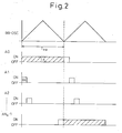
- Figure 2 shows the waveform of the triangular wave of period T FM that the baseband oscillator (BB-OSC) 10 outputs, and the transition of the function of the antenna elements A0 to AN A -1 accomplished by the switches 16 and 20 controlled in synchronism with the triangular wave.
- the triangular wave is shown only for two periods, but it should be noted that the illustrated control is performed repeatedly.
- the antenna element A0 in the first period of the triangular wave, the antenna element A0 is selected as the transmitting antenna by the switch 16, and the other antennas A1 to AN A -1 are sequentially selected as receiving antennas in time division fashion.
- the antenna element AN A -1 is selected as the transmitting antenna, and the other antennas A0 to AN A -2 are sequentially selected as receiving antennas in time division fashion.
- the array that uses the extended signal vector defined by the following equation has an effective aperture of 2(N A -1)d because of the synthetic aperture accomplished by the time division switching.
- an array antenna by transmitting alternately from the two outermost antenna elements of an array antenna having N A antenna elements, and by receiving the reflected wave from the target at the other antenna elements in time division fashion, an array antenna can be achieved that has an effective aperture of 2(N A -1), which means that the effective aperture is increased to about twice the physical aperture.
- the invention provides an effective compensating means when applying in the direction-of-arrival estimator 26 ( Figure 1 ) a spatial smoothing technique that suppresses correlative interference waves due to multiple reflections, etc. but that reduces the effective aperture.
- the array antenna of the present invention has excellent symmetry, which means that, in the case of an equispaced linear array antenna, the received data, when the transmitting antenna is the antenna element A0 and the received data when the transmitting antenna is the antenna element AN A -1, are in a rotational invariance relationship with each other (that is, it can be regarded as one equispaced linear array). Therefore, the invention provides a useful means when applying in the direction-of-arrival estimator 26 ( Figure 1 ) the ESPRIT algorithm that can achieve super resolution characteristics.
- v 1 exp j ⁇ 2 ⁇ ⁇ ⁇ ⁇ d sin ⁇ i
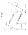
- equation (8) the range of ⁇ 1 that can be estimated by the angle-of-arrival estimator is given by equation (8); as can be seen, when the range of the principal value of the inverse trigonometric function is considered, the range increases as d becomes closer to ⁇ /2, and reduces as d becomes larger with respect to ⁇ /2. It can therefore be seen that the angle range that can be measured can be increased by reducing the apparent magnitude of d.
- ⁇ 1 sin - 1 ⁇ d ⁇ 1 2 ⁇ ⁇ ⁇ tan - 1 ⁇ Im v 1 Re v 1
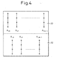
- Figure 4 shows an array antenna used in a radar apparatus according to a second embodiment of the present invention.
- the base plate forming the antenna surface is divided into an upper bank 30 and a lower bank 32, and the antenna elements arranged on the upper and lower banks 30 and 32 are offset relative to each other in a horizontal direction. With this arrangement, the effective element spacing is reduced to one half, achieving a corresponding increase in the field of view of the radar.
- the outermost antenna elements AUO and AUN-1 on the upper bank are alternately selected for use as the transmitting antenna.
- the example shown here is an equispaced array, but in the case of a non-equispaced array also, the effective element spacing can be reduced by arranging the antenna elements on one bank so as not to overlap, in position, any of the antenna elements on the other bank when viewed along the horizontal direction.
- the problem of reduced gain can be solved by arranging one antenna row into a plurality of rows.
- Figure 5 shows the configuration of a radar apparatus according to a third embodiment of the radar apparatus of Figure 1 ; the same component elements as those in Figure 1 are designated by the same reference numerals, and a description of such elements will not be repeated here.
- a phase shifter 34 is rendered inoperative with its phase shift amount set to zero, but is made operative in a tracking mode in which target tracking is performed by directing the transmit beam to the target after the direction of the target has been determined in the normal mode.
- the antenna elements A0 and AN A -1 are both connected to the hybrid 18 and thus function as the transmitting antennas.
- a direction-of-arrival estimator 26' determines the phase shift amount ⁇ necessary to direct the transmit beam in the direction ⁇ and applies it to the phase shifter 34.
- the transmit waves are directed in the particular direction ⁇ so as to be able to track the target.
- reception is performed using the antenna elements A1 to AN A -2 located inward of the transmitting antennas and, based on the target's direction ⁇ estimated from the received signals, a new phase shift amount ⁇ is determined and fed back to the phase shifter 34. It is desirable that the switching from the normal mode to the tracking mode be performed by computing the risk appropriate to the velocity and position of the target.
- the transmitting antennas need not necessarily be set as the outermost antenna elements; in fact, the tracking mode could be implemented if a plurality of suitably selected antenna elements, including ones located inward of the outermost elements, were used as the transmitting antennas.
- the tracking mode that uses the two outermost antenna elements as the transmitting antennas can be easily implemented by just adding one piece of hardware, i.e., the phase shifter.
- the result ⁇ 0 of the direction-of-arrival estimation performed by using one outermost antenna element A0 as the transmitting antenna and the other antenna elements A1 to AN A -1 as the receiving antennas must agree with the result ⁇ 1 of the direction-of-arrival estimation performed by using the other outermost antenna element AN A -1 as the transmitting antenna and the other antenna elements A0 to AN A -2 as the receiving antennas.
- the calibration of the array antenna that is, the determination of the correction values for the direction vector a( ⁇ ) which is a function of the geometric parameters of the array antenna, can be performed.
- the directions ⁇ 0 and ⁇ 1 are measured while varying the reference target position a number of times equal to the number of correction values, and a combination of correction values that minimizes the difference between the two is determined. Further, by using the algorithm described by I. S. D. Solomon, et al. in "Receiver array calibration using disparate sources," IEEE Trans. Antenna Propagat., vol. 47, pp. 496-505 , for example, all the correction values can be determined based on a single reference target position. In the calibration performed in the tracking mode of the apparatus of Figure 5 , the two outermost antenna elements are set as the transmitting antennas, and the correction values are determined so that a single angle ⁇ can be obtained from the received signals obtained at the inwardly located antenna elements.
- Figure 6 shows the configuration of a radar apparatus according to still another embodiment of the present invention.
- the same component elements as those in Figure 1 are designated by the same reference numerals, and a description of such elements will not be repeated here.
- the switches 16 used in the first embodiment to switch the outermost antenna elements A0 and AN A -1 between transmit and receive modes are replaced by circulators as duplexers (or unidirectional devices such as hybrids or switches) 40 and 42 and bidirectional amplifier modules (DD-AMP) 44 and 46 which connect the transmitting-side inputs of the respective duplexers 40 and 42 to the transmitter output or connect the receiving-side outputs of the respective duplexers-40 and 42 to the receiver input.
- circulators as duplexers (or unidirectional devices such as hybrids or switches) 40 and 42 and bidirectional amplifier modules (DD-AMP) 44 and 46 which connect the transmitting-side inputs of the respective duplexers 40 and 42 to the transmitter output or connect the receiving-side outputs of the respective duplexers-40 and 42 to the receiver input.
- DD-AMP bidirectional amplifier modules
- the receiving-side outputs of the duplexers 40 and 42 are connected via LNA, SPDT, HPA, SPDT, and LNA to the receiver input, that is, the switch 20 in Figure 6 ; on the other hand, when they are set as shown in Figure 8 , the transmitter output, that is, the hybrid 18 in Figure 6 , is connected via SPDT, HPA, SPDT, and HPA to the transmitting-side inputs of the duplexers 40 and 42.
- FIG 10 shows one modified example of Figure 6 .
- the receiving-side outputs of the bidirectional amplifier modules 44 and 46 are directly connected to the receiver input without interposing the switch 20 and, when the antenna A0 or AN A -1 is functioning as a receiving antenna, the switch 26 is controlled so as not to select any one of the antennas.
- the bidirectional amplifier modules 44 and 46 contain HPAs, the HPA 15 in Figure 6 is omitted, and the HPA that is used in both transmit and receive modes in each of the bidirectional amplifier modules 44 and 46 is replaced by a high-gain front-end amplifier (HGA).
- HGA high-gain front-end amplifier
- the invention also relates to the following numbered embodiments I. to X.
Landscapes
- Engineering & Computer Science (AREA)
- Radar, Positioning & Navigation (AREA)
- Remote Sensing (AREA)
- Computer Networks & Wireless Communication (AREA)
- Physics & Mathematics (AREA)
- General Physics & Mathematics (AREA)
- Radar Systems Or Details Thereof (AREA)
- Variable-Direction Aerials And Aerial Arrays (AREA)
Applications Claiming Priority (2)
| Application Number | Priority Date | Filing Date | Title |
|---|---|---|---|
| JP2004283515A JP4833534B2 (ja) | 2004-09-29 | 2004-09-29 | レーダ装置 |
| EP04030277.0A EP1650579B1 (fr) | 2004-09-29 | 2004-12-21 | Reseau d'antennes commutable pour l'estimation de la direction d' incidence d'un signal reçu |
Related Parent Applications (3)
| Application Number | Title | Priority Date | Filing Date |
|---|---|---|---|
| EP04030277.0A Division EP1650579B1 (fr) | 2004-09-29 | 2004-12-21 | Reseau d'antennes commutable pour l'estimation de la direction d' incidence d'un signal reçu |
| EP04030277.0A Division-Into EP1650579B1 (fr) | 2004-09-29 | 2004-12-21 | Reseau d'antennes commutable pour l'estimation de la direction d' incidence d'un signal reçu |
| EP04030277.0 Division | 2004-12-21 |
Publications (2)
| Publication Number | Publication Date |
|---|---|
| EP2031415A1 true EP2031415A1 (fr) | 2009-03-04 |
| EP2031415B1 EP2031415B1 (fr) | 2010-11-03 |
Family
ID=35478236
Family Applications (2)
| Application Number | Title | Priority Date | Filing Date |
|---|---|---|---|
| EP08021230A Expired - Lifetime EP2031415B1 (fr) | 2004-09-29 | 2004-12-21 | Réseau d'antennes commutable pour l'estimation de la direction d'incidence d'un signal reçu |
| EP04030277.0A Expired - Lifetime EP1650579B1 (fr) | 2004-09-29 | 2004-12-21 | Reseau d'antennes commutable pour l'estimation de la direction d' incidence d'un signal reçu |
Family Applications After (1)
| Application Number | Title | Priority Date | Filing Date |
|---|---|---|---|
| EP04030277.0A Expired - Lifetime EP1650579B1 (fr) | 2004-09-29 | 2004-12-21 | Reseau d'antennes commutable pour l'estimation de la direction d' incidence d'un signal reçu |
Country Status (4)
| Country | Link |
|---|---|
| US (1) | US7196656B2 (fr) |
| EP (2) | EP2031415B1 (fr) |
| JP (1) | JP4833534B2 (fr) |
| DE (1) | DE602004029953D1 (fr) |
Cited By (2)
| Publication number | Priority date | Publication date | Assignee | Title |
|---|---|---|---|---|
| DE102010040438A1 (de) * | 2009-09-10 | 2011-04-14 | Fujitsu Ten Ltd., Kobe-shi | Radarvorrichtung |
| EP2981842A1 (fr) * | 2013-04-03 | 2016-02-10 | Robert Bosch GmbH | Système radar et procédé avec réseau d'antennes présentant deux états de connexion à modulation différente |
Families Citing this family (43)
| Publication number | Priority date | Publication date | Assignee | Title |
|---|---|---|---|---|
| JP2006003303A (ja) * | 2004-06-21 | 2006-01-05 | Fujitsu Ten Ltd | レーダ装置 |
| JP4805591B2 (ja) * | 2005-03-17 | 2011-11-02 | 富士通株式会社 | 電波到来方向の追尾方法及び電波到来方向追尾装置 |
| JP4755849B2 (ja) * | 2005-05-23 | 2011-08-24 | 富士通株式会社 | 信号到来方向推定装置 |
| JP5635723B2 (ja) * | 2006-01-30 | 2014-12-03 | 富士通株式会社 | 目標検出装置およびシステム |
| US7804445B1 (en) * | 2006-03-02 | 2010-09-28 | Bae Systems Information And Electronic Systems Integration Inc. | Method and apparatus for determination of range and direction for a multiple tone phased array radar in a multipath environment |
| WO2008053685A1 (fr) * | 2006-11-01 | 2008-05-08 | Murata Manufacturing Co., Ltd. | Procédé de détection de cible par radar et dispositif de radar utilisant le procédé de détection de cible |
| JP2009080024A (ja) | 2007-09-26 | 2009-04-16 | Fujitsu Ltd | 探知測距装置および探知測距方法 |
| US7639171B2 (en) * | 2007-09-27 | 2009-12-29 | Delphi Technologies, Inc. | Radar system and method of digital beamforming |
| DE102008038365A1 (de) * | 2008-07-02 | 2010-01-07 | Adc Automotive Distance Control Systems Gmbh | Fahrzeug-Radarsystem und Verfahren zur Bestimmung einer Position zumindest eines Objekts relativ zu einem Fahrzeug |
| JP5470836B2 (ja) * | 2008-12-19 | 2014-04-16 | 富士通株式会社 | 探知測距装置および探知測距装置の設計方法 |
| US8344940B2 (en) * | 2009-01-22 | 2013-01-01 | Mando Corporation | Apparatus and sensor for adjusting sensor vertical alignment |
| WO2010113926A1 (fr) * | 2009-03-31 | 2010-10-07 | 日本電気株式会社 | Dispositif de mesure, système de mesure, procédé de mesure, et programme |
| KR101775572B1 (ko) | 2009-04-06 | 2017-09-06 | 콘티 테믹 마이크로일렉트로닉 게엠베하 | 송신 신호와 수신 신호를 디커플링하고 간섭 방사를 억제하기 위한 어레이와 방법을 채용한 레이더 시스템 |
| JP4790045B2 (ja) * | 2009-05-19 | 2011-10-12 | 本田技研工業株式会社 | レーダの軸ずれを判定する装置 |
| US9590733B2 (en) * | 2009-07-24 | 2017-03-07 | Corning Optical Communications LLC | Location tracking using fiber optic array cables and related systems and methods |
| JP5659472B2 (ja) * | 2009-09-01 | 2015-01-28 | 富士通株式会社 | 到来方向推定装置及び方法 |
| DE102010002004A1 (de) * | 2010-02-16 | 2011-08-18 | Astyx GmbH, 85521 | Abstands- und Geschwindigkeitsmessvorrichtung und -verfahren |
| JP5630034B2 (ja) * | 2010-03-04 | 2014-11-26 | 富士通株式会社 | レーダ装置及び目標探知方法 |
| AU2011232897B2 (en) | 2010-03-31 | 2015-11-05 | Corning Optical Communications LLC | Localization services in optical fiber-based distributed communications components and systems, and related methods |
| JP5617334B2 (ja) | 2010-05-10 | 2014-11-05 | 富士通株式会社 | レーダ装置及び目標探知方法 |
| JP5093298B2 (ja) * | 2010-06-04 | 2012-12-12 | 株式会社デンソー | 方位検出装置 |
| US8570914B2 (en) | 2010-08-09 | 2013-10-29 | Corning Cable Systems Llc | Apparatuses, systems, and methods for determining location of a mobile device(s) in a distributed antenna system(s) |
| JP5712649B2 (ja) | 2011-02-07 | 2015-05-07 | 富士通株式会社 | レーダ装置及び目標探知方法 |
| DE102011113018A1 (de) * | 2011-09-09 | 2013-03-14 | Astyx Gmbh | Abbildender Radarsensor mit schmaler Antennenkeule und weitem Winkel-Detektionsbereich |
| US9781553B2 (en) | 2012-04-24 | 2017-10-03 | Corning Optical Communications LLC | Location based services in a distributed communication system, and related components and methods |
| WO2013181247A1 (fr) | 2012-05-29 | 2013-12-05 | Corning Cable Systems Llc | Localisation au moyen d'ultrasons de dispositifs clients à complément de navigation par inertie dans des systèmes de communication distribués et dispositifs et procédés associés |
| US9158864B2 (en) | 2012-12-21 | 2015-10-13 | Corning Optical Communications Wireless Ltd | Systems, methods, and devices for documenting a location of installed equipment |
| EP2876460B1 (fr) * | 2013-11-26 | 2019-05-15 | Veoneer Sweden AB | Radar de véhicule avec deux agencements d'antenne d'émetteur |
| US20150204969A1 (en) * | 2014-01-17 | 2015-07-23 | SpotterRF LLC | Target spotting and tracking apparatus and method |
| JP5737441B2 (ja) * | 2014-02-17 | 2015-06-17 | 富士通株式会社 | レーダ装置及び目標探知方法 |
| CN106033978B (zh) * | 2015-03-19 | 2018-12-21 | 北京佰才邦技术有限公司 | 信号处理方法和装置 |
| DE102015222884A1 (de) | 2015-11-19 | 2017-05-24 | Conti Temic Microelectronic Gmbh | Radarsystem mit verschachtelt seriellem Senden und parallelem Empfangen |
| EP3406031B1 (fr) | 2016-01-18 | 2024-10-30 | Viavi Solutions Inc. | Procédé et appareil pour la détection de distorsion ou de corruption de signaux de communications cellulaires |
| US9648580B1 (en) | 2016-03-23 | 2017-05-09 | Corning Optical Communications Wireless Ltd | Identifying remote units in a wireless distribution system (WDS) based on assigned unique temporal delay patterns |
| US10222472B2 (en) * | 2016-09-30 | 2019-03-05 | Veoneer Us, Inc. | System and method for detecting heading and velocity of a target object |
| EP3531505B1 (fr) * | 2016-12-05 | 2020-10-07 | Huawei Technologies Co., Ltd. | Appareil et procédé de suivi de faisceaux, et système d'antennes |
| US11754671B2 (en) * | 2018-05-07 | 2023-09-12 | Mitsubishi Electric Corporation | Incoming wave count estimation apparatus and incoming wave count incoming direction estimation apparatus |
| JP7152193B2 (ja) * | 2018-06-07 | 2022-10-12 | 株式会社デンソーテン | レーダ装置 |
| CN110988806A (zh) * | 2019-11-22 | 2020-04-10 | 中船重工(武汉)凌久电子有限责任公司 | 一种时分复用雷达阵面实现系统 |
| CN112653396B (zh) * | 2020-12-31 | 2023-04-07 | 电子科技大学 | 一种基于500nm GaAs pHEMT工艺的超宽带双向放大器 |
| CN116125431A (zh) * | 2022-09-06 | 2023-05-16 | Oppo广东移动通信有限公司 | 激光雷达和电子设备 |
| US12571909B2 (en) * | 2022-09-28 | 2026-03-10 | Deere & Company | Systems and methods for controlling the operation of a vehicular radar system |
| US12436273B2 (en) | 2022-09-28 | 2025-10-07 | Deere & Company | Systems and methods for scheduling radar scan patterns in a vehicular radar system |
Citations (6)
| Publication number | Priority date | Publication date | Assignee | Title |
|---|---|---|---|---|
| US3978482A (en) * | 1975-03-24 | 1976-08-31 | Hughes Aircraft Company | Dynamically focused thinned array |
| EP0898174A1 (fr) * | 1997-08-18 | 1999-02-24 | Fujitsu Limited | Appareil Radar |
| EP0987561A2 (fr) * | 1998-09-14 | 2000-03-22 | Kabushiki Kaisha Toyota Chuo Kenkyusho | Radar à holographie |
| JP2000155171A (ja) | 1998-09-14 | 2000-06-06 | Toyota Central Res & Dev Lab Inc | ホログラフィックレ―ダ |
| US6137434A (en) * | 1996-05-02 | 2000-10-24 | Honda Giken Kogyo Kabushiki Kaisha | Multibeam radar system |
| EP1486796A2 (fr) * | 2003-06-09 | 2004-12-15 | Fujitsu Ten Limited | Dispositif radar comprénant une matrice de commutation pour formation adaptive de faisceaux pour le distributéur de réception et pour commutation du distributéur d'émission |
Family Cites Families (11)
| Publication number | Priority date | Publication date | Assignee | Title |
|---|---|---|---|---|
| US3618090A (en) * | 1960-04-05 | 1971-11-02 | Us Navy | Radar |
| US4017854A (en) * | 1975-08-21 | 1977-04-12 | Sperry Rand Corporation | Apparatus for angular measurement and beam forming with baseband radar systems |
| JP4238375B2 (ja) * | 1997-12-25 | 2009-03-18 | 株式会社豊田中央研究所 | レーダ装置 |
| DE19842250A1 (de) | 1998-09-15 | 2000-03-16 | Mannesmann Vdo Ag | Verfahren zur Bestimmung des Abstandes zwischen einem Objekt und einer sich örtlich verändernden Einrichtung, insbesondere einem Kraftfahrzeug |
| US6104346A (en) * | 1998-11-06 | 2000-08-15 | Ail Systems Inc. | Antenna and method for two-dimensional angle-of-arrival determination |
| EP1149306B1 (fr) * | 1999-01-07 | 2003-04-02 | Siemens Aktiengesellschaft | Procede pour detecter des cibles et pour determiner leur direction pour un radar dans un vehicule automobile |
| JP3622565B2 (ja) * | 1999-03-31 | 2005-02-23 | 株式会社デンソー | レーダ装置 |
| KR100452536B1 (ko) * | 2000-10-02 | 2004-10-12 | 가부시키가이샤 엔.티.티.도코모 | 이동통신기지국 장치 |
| JP2004150966A (ja) * | 2002-10-31 | 2004-05-27 | Fujitsu Ltd | アレーアンテナ |
| JP3833606B2 (ja) * | 2002-12-19 | 2006-10-18 | 三菱電機株式会社 | 車載レーダ装置 |
| IL154835A (en) * | 2003-03-10 | 2007-12-03 | Avner Rosenberg | A system for identifying friendly or hostile ground elements on a battlefield |
-
2004
- 2004-09-29 JP JP2004283515A patent/JP4833534B2/ja not_active Expired - Fee Related
- 2004-12-21 EP EP08021230A patent/EP2031415B1/fr not_active Expired - Lifetime
- 2004-12-21 EP EP04030277.0A patent/EP1650579B1/fr not_active Expired - Lifetime
- 2004-12-21 DE DE602004029953T patent/DE602004029953D1/de not_active Expired - Lifetime
- 2004-12-21 US US11/018,985 patent/US7196656B2/en not_active Expired - Fee Related
Patent Citations (6)
| Publication number | Priority date | Publication date | Assignee | Title |
|---|---|---|---|---|
| US3978482A (en) * | 1975-03-24 | 1976-08-31 | Hughes Aircraft Company | Dynamically focused thinned array |
| US6137434A (en) * | 1996-05-02 | 2000-10-24 | Honda Giken Kogyo Kabushiki Kaisha | Multibeam radar system |
| EP0898174A1 (fr) * | 1997-08-18 | 1999-02-24 | Fujitsu Limited | Appareil Radar |
| EP0987561A2 (fr) * | 1998-09-14 | 2000-03-22 | Kabushiki Kaisha Toyota Chuo Kenkyusho | Radar à holographie |
| JP2000155171A (ja) | 1998-09-14 | 2000-06-06 | Toyota Central Res & Dev Lab Inc | ホログラフィックレ―ダ |
| EP1486796A2 (fr) * | 2003-06-09 | 2004-12-15 | Fujitsu Ten Limited | Dispositif radar comprénant une matrice de commutation pour formation adaptive de faisceaux pour le distributéur de réception et pour commutation du distributéur d'émission |
Non-Patent Citations (2)
| Title |
|---|
| I. S. D. SOLOMON ET AL.: "Receiver array calibration using disparate sources", IEEE TRANS. ANTENNA PROPAGAT, vol. 47, pages 496 - 505 |
| PATENT ABSTRACTS OF JAPAN vol. 2000, no. 09 13 October 2000 (2000-10-13) * |
Cited By (4)
| Publication number | Priority date | Publication date | Assignee | Title |
|---|---|---|---|---|
| DE102010040438A1 (de) * | 2009-09-10 | 2011-04-14 | Fujitsu Ten Ltd., Kobe-shi | Radarvorrichtung |
| DE102010040438A8 (de) | 2009-09-10 | 2014-02-06 | Fujitsu Ten Ltd. | Radarvorrichtung |
| DE102010040438B4 (de) * | 2009-09-10 | 2017-08-24 | Fujitsu Ten Ltd. | Radarvorrichtung |
| EP2981842A1 (fr) * | 2013-04-03 | 2016-02-10 | Robert Bosch GmbH | Système radar et procédé avec réseau d'antennes présentant deux états de connexion à modulation différente |
Also Published As
| Publication number | Publication date |
|---|---|
| US20060066474A1 (en) | 2006-03-30 |
| EP2031415B1 (fr) | 2010-11-03 |
| EP1650579B1 (fr) | 2015-06-10 |
| JP2006098181A (ja) | 2006-04-13 |
| JP4833534B2 (ja) | 2011-12-07 |
| DE602004029953D1 (de) | 2010-12-16 |
| US7196656B2 (en) | 2007-03-27 |
| EP1650579A1 (fr) | 2006-04-26 |
Similar Documents
| Publication | Publication Date | Title |
|---|---|---|
| EP2031415B1 (fr) | Réseau d'antennes commutable pour l'estimation de la direction d'incidence d'un signal reçu | |
| US11619706B2 (en) | Radar device | |
| US11422249B2 (en) | Radar device and method for detecting radar targets | |
| US10890652B2 (en) | Radar apparatus | |
| EP2045612B1 (fr) | Appareil de détection et de mesure de distance et procédé de détection et de mesure de distance | |
| JP3833606B2 (ja) | 車載レーダ装置 | |
| US9470782B2 (en) | Method and apparatus for increasing angular resolution in an automotive radar system | |
| CN101430378B (zh) | 实现目标体方向的精确检测的车辆安装方向检测设备 | |
| EP2541679A1 (fr) | Dispositif de formation de faisceau à large bande, dispositif d'orientation de faisceau à large bande et procédés correspondants | |
| EP1580572A1 (fr) | Système radar à formation de faisceau numérique | |
| CN111656212A (zh) | 雷达装置 | |
| US20240427011A1 (en) | Radar device and method for detecting radar targets | |
| US11933875B2 (en) | Radar apparatus | |
| US20210149038A1 (en) | Radar device | |
| CN106374235A (zh) | 一种基于子阵化四维天线阵的mimo雷达装置 | |
| US20240039173A1 (en) | Multiple input multiple steered output (mimso) radar | |
| JP2020056780A (ja) | レーダ装置 | |
| JP2026506396A (ja) | レーダ角度推定を行うための方法 | |
| JP2010156708A (ja) | 車載用ミリ波レーダ装置 | |
| JP2004117246A (ja) | アンテナ装置 | |
| US11431400B2 (en) | Method and apparatus for forming a plurality of beamformed signals using a plurality of received signals | |
| EP3819662B1 (fr) | Radar de véhicule avec diversité de fréquences | |
| JP2009031185A (ja) | レーダ装置及びターゲット検出方法 | |
| JP4294665B2 (ja) | ミリ波レーダ装置 | |
| EP4345499A1 (fr) | Orientation bidirectionnelle de diagramme de faisceau radar |
Legal Events
| Date | Code | Title | Description |
|---|---|---|---|
| PUAI | Public reference made under article 153(3) epc to a published international application that has entered the european phase |
Free format text: ORIGINAL CODE: 0009012 |
|
| AC | Divisional application: reference to earlier application |
Ref document number: 1650579 Country of ref document: EP Kind code of ref document: P |
|
| AK | Designated contracting states |
Kind code of ref document: A1 Designated state(s): DE FR GB |
|
| 17P | Request for examination filed |
Effective date: 20090904 |
|
| AKX | Designation fees paid |
Designated state(s): DE FR GB |
|
| 17Q | First examination report despatched |
Effective date: 20091218 |
|
| GRAP | Despatch of communication of intention to grant a patent |
Free format text: ORIGINAL CODE: EPIDOSNIGR1 |
|
| GRAS | Grant fee paid |
Free format text: ORIGINAL CODE: EPIDOSNIGR3 |
|
| GRAA | (expected) grant |
Free format text: ORIGINAL CODE: 0009210 |
|
| AC | Divisional application: reference to earlier application |
Ref document number: 1650579 Country of ref document: EP Kind code of ref document: P |
|
| AK | Designated contracting states |
Kind code of ref document: B1 Designated state(s): DE FR GB |
|
| REG | Reference to a national code |
Ref country code: GB Ref legal event code: FG4D |
|
| REF | Corresponds to: |
Ref document number: 602004029953 Country of ref document: DE Date of ref document: 20101216 Kind code of ref document: P |
|
| PLBE | No opposition filed within time limit |
Free format text: ORIGINAL CODE: 0009261 |
|
| STAA | Information on the status of an ep patent application or granted ep patent |
Free format text: STATUS: NO OPPOSITION FILED WITHIN TIME LIMIT |
|
| 26N | No opposition filed |
Effective date: 20110804 |
|
| REG | Reference to a national code |
Ref country code: DE Ref legal event code: R097 Ref document number: 602004029953 Country of ref document: DE Effective date: 20110804 |
|
| REG | Reference to a national code |
Ref country code: FR Ref legal event code: PLFP Year of fee payment: 12 |
|
| PGFP | Annual fee paid to national office [announced via postgrant information from national office to epo] |
Ref country code: GB Payment date: 20151216 Year of fee payment: 12 |
|
| PGFP | Annual fee paid to national office [announced via postgrant information from national office to epo] |
Ref country code: FR Payment date: 20151110 Year of fee payment: 12 |
|
| GBPC | Gb: european patent ceased through non-payment of renewal fee |
Effective date: 20161221 |
|
| REG | Reference to a national code |
Ref country code: FR Ref legal event code: ST Effective date: 20170831 |
|
| PG25 | Lapsed in a contracting state [announced via postgrant information from national office to epo] |
Ref country code: FR Free format text: LAPSE BECAUSE OF NON-PAYMENT OF DUE FEES Effective date: 20170102 |
|
| PG25 | Lapsed in a contracting state [announced via postgrant information from national office to epo] |
Ref country code: GB Free format text: LAPSE BECAUSE OF NON-PAYMENT OF DUE FEES Effective date: 20161221 |
|
| PGFP | Annual fee paid to national office [announced via postgrant information from national office to epo] |
Ref country code: DE Payment date: 20171212 Year of fee payment: 14 |
|
| REG | Reference to a national code |
Ref country code: DE Ref legal event code: R119 Ref document number: 602004029953 Country of ref document: DE |
|
| PG25 | Lapsed in a contracting state [announced via postgrant information from national office to epo] |
Ref country code: DE Free format text: LAPSE BECAUSE OF NON-PAYMENT OF DUE FEES Effective date: 20190702 |