EP2032765B1 - Fahrzeugsicherheitsbarrieren - Google Patents
Fahrzeugsicherheitsbarrieren Download PDFInfo
- Publication number
- EP2032765B1 EP2032765B1 EP07725982.8A EP07725982A EP2032765B1 EP 2032765 B1 EP2032765 B1 EP 2032765B1 EP 07725982 A EP07725982 A EP 07725982A EP 2032765 B1 EP2032765 B1 EP 2032765B1
- Authority
- EP
- European Patent Office
- Prior art keywords
- rail
- anchor
- upright
- section
- vehicle safety
- Prior art date
- Legal status (The legal status is an assumption and is not a legal conclusion. Google has not performed a legal analysis and makes no representation as to the accuracy of the status listed.)
- Not-in-force
Links
- 230000004888 barrier function Effects 0.000 title claims description 64
- 125000006850 spacer group Chemical group 0.000 claims description 13
- 230000001154 acute effect Effects 0.000 claims description 6
- 239000007787 solid Substances 0.000 claims description 2
- 230000002787 reinforcement Effects 0.000 description 14
- 230000003116 impacting effect Effects 0.000 description 6
- 230000000694 effects Effects 0.000 description 3
- 238000012360 testing method Methods 0.000 description 3
- 238000003466 welding Methods 0.000 description 2
- 230000002411 adverse Effects 0.000 description 1
- 238000013459 approach Methods 0.000 description 1
- 238000009434 installation Methods 0.000 description 1
- 238000004519 manufacturing process Methods 0.000 description 1
- 239000000463 material Substances 0.000 description 1
- 238000012986 modification Methods 0.000 description 1
- 230000004048 modification Effects 0.000 description 1
- 230000000452 restraining effect Effects 0.000 description 1
- 230000003019 stabilising effect Effects 0.000 description 1
- 238000010200 validation analysis Methods 0.000 description 1
Images


Classifications
-
- E—FIXED CONSTRUCTIONS
- E01—CONSTRUCTION OF ROADS, RAILWAYS, OR BRIDGES
- E01F—ADDITIONAL WORK, SUCH AS EQUIPPING ROADS OR THE CONSTRUCTION OF PLATFORMS, HELICOPTER LANDING STAGES, SIGNS, SNOW FENCES, OR THE LIKE
- E01F15/00—Safety arrangements for slowing, redirecting or stopping errant vehicles, e.g. guard posts or bollards; Arrangements for reducing damage to roadside structures due to vehicular impact
- E01F15/14—Safety arrangements for slowing, redirecting or stopping errant vehicles, e.g. guard posts or bollards; Arrangements for reducing damage to roadside structures due to vehicular impact specially adapted for local protection, e.g. for bridge piers, for traffic islands
- E01F15/143—Protecting devices located at the ends of barriers
-
- E—FIXED CONSTRUCTIONS
- E01—CONSTRUCTION OF ROADS, RAILWAYS, OR BRIDGES
- E01F—ADDITIONAL WORK, SUCH AS EQUIPPING ROADS OR THE CONSTRUCTION OF PLATFORMS, HELICOPTER LANDING STAGES, SIGNS, SNOW FENCES, OR THE LIKE
- E01F15/00—Safety arrangements for slowing, redirecting or stopping errant vehicles, e.g. guard posts or bollards; Arrangements for reducing damage to roadside structures due to vehicular impact
- E01F15/02—Continuous barriers extending along roads or between traffic lanes
- E01F15/04—Continuous barriers extending along roads or between traffic lanes essentially made of longitudinal beams or rigid strips supported above ground at spaced points
Definitions
- the present invention relates to vehicle safety barriers.
- Vehicle safety barriers for road use typically comprise one or more horizontal rails supported by posts spaced along the roadside. If a vehicle leaves the roadway for some reason, it impacts the rail and is restrained. Such barriers are a common sight on roads (etc) and are often referred to generically as "Armco".
- barriers are used extensively where there are sensitive or dangerous structures or areas near to the roadway.
- An example is a support for a bridge over the roadway; if a vehicle were to leave the roadway and impact the bridge support then a potentially serious incident could result.
- a barrier serves to deflect the vehicle away from a course that would otherwise result in an impact.
- DE 102 31 903 discloses a vehicle safety barrier with the features of the preamble of claim 1.
- the present invention therefore provides a vehicle safety barrier, comprising a length of rail supported by posts and, at the end of the rail and connected thereto, an anchor comprising first and second uprights, the anchor being located behind the line defined by the rail, characterised in that a bracing is provided between the first and second uprights and wherein the anchor is oriented such that the line defined by the first and second uprights extends from the end of the rail back towards the posts of the rail and is at an acute angle to the line defined by the posts, this acute angle being measured in the area formed between the posts of the rail and the uprights of the anchor and wherein the end of the rail is angled inwardly relative to the posts, the rail extending past the first upright to a point of connection with the second upright.
- the anchor is in fact a potential risk point. Vehicles that impact at or shortly before the anchor meet what is in effect a rigid object in their path. Angling the anchor to the direction of travel allows an impacting vehicle to be more smoothly deflected past the anchor.
- the bracing comprises at least one inclined strut extending between the uprights.
- the inclined strut can extend upwardly from the first upright to the second upright; in this way it is best able to withstand forces in the rail that are transferred to the anchor, while minimising the overall height of the anchor.
- the end of the rail is angled inwardly relative to the posts.
- the rail extends past the first upright to a point of connection with the second upright.
- the rail is preferably a W section.
- This can be reinforced, at least in its end section. Reinforcement allows the rail to exert a greater returning force on a vehicle to deflect its path away from the anchor with greater urgency.
- a suitable reinforcement for both the rail and for a W-section deflector bar comprises a length of C-section behind the W-section, such that the free edges of the C-section extend into the two recesses of the rear of the W-section. This is particularly straightforward to manufacture and to install.
- the central peak at the rear of the W section can sit in the channel defined by the C section and the two can be attached to a post using the same fixing. No further join need be provided, although the two could evidently be welded or otherwise joined along their length if this were felt worthwhile.
- one of the uprights is provided with a bracket for attaching a barrier rail, the bracket comprising an attachment means for accepting the rail at an acute angle to the anchor and a spacer element between the rail and the anchor.
- the attachment means can absorb longitudinal forces in the rail, while the spacer element can resist rotation of the rail about its point of attachment to the anchor.
- the spacer element can be a hollow section such as a trapezoidal section. It is preferably located between the rail and the bracing.
- the attachment means (or part of it) can also extend between the spacer element and the rail, so that the spacer element is crushed between the attachment means and the anchor bracing.
- a truss can extend from the rail to the anchor or to ground, to assist further in stabilising the barrier under impact.
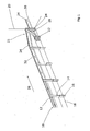
- FIG. 1 shows a safety barrier termination according to the present invention. This is described and claimed in our two copending applications filed simultaneously with this application and each entitled “Vehicle Safety Barriers” and “Rail for Vehicle Safety Barriers”, and the disclosures of which is hereby incorporated by reference.
- a standard W-section safety barrier 10 is shown, which consists of a W-section rail 12 supported by posts 14. Each post 14 is set into a socket 16 that is embedded in to the ground surface 18; other means of securing the posts are also known, such as driving the socket directly into the ground.
- the barrier 10 needs to be terminated prior to an obstruction in the form of a vertical concrete block 20.
- the design parameters for the termination shown in figure 1 were that it should not intrude or otherwise be supported by the vertical concrete block 20.
- the result is a universal safety barrier termination which does not rely in any way upon support provided by the obstruction 20 in order to meet the necessary testing requirements.
- a vehicle impacting the barrier within the parameters of the test requirements will be guided to safety without impacting the obstruction 20.
- the obstruction 20 could be replaced with any other form of barrier or obstruction.
- validation of this design will enable it to be used as a termination for a new or existing W-section barrier at an interface with any other form of barrier or parapet.
- the principles of this invention can be applied to terminate any other form of vehicle safety barrier prior to an obstruction or interface.
- the termination 21 consists of first upright 22 and second upright 24, both formed of I-section struts. When viewed in the direction of traffic flow 26, the first upright 22 is before the second upright 24.
- a bracing structure 28 is provided between the first and second upright 22, 24, and consists of an inclined box section running between the I-section uprights, from a low point at its connection with the first upright 22 to a highest point at its connection with the second upright 24. Other sections such as C- or I-sections could also be used. Given that (as will be explained later) most forces and moments exerted on the termination 21 will be applied via the second upright 24, the inclining of the bracing structure 28 assists in absorbing these forces.
- the fact that the bracing structure 28 attaches to the first upright 22 at a relatively low height means that the first upright 22 can be relatively short, shorter than the second upright 24. Given that approaching vehicles meet the first upright 22 early, this can improve the impact profile of the termination 21.
- a deflector (or “kicker") bar 30 extends from the first upright 22 to the second 24 and beyond, and is held in place at securing points on each upright.
- the deflector bar 30 is generally positioned at a level slightly above ground level 18 affixed at the top of the first upright 22. It extends generally alongside the direction of travel 26, past the front of the second upright 24 and in front of the vertical concrete block 20. In total, the length by which the deflector bar extends beyond the second upright, alongside the vertical concrete block 20, is slightly more than the distance between the external faces of the uprights, i.e. the spacing of the uprights including their thicknesses.
- the total length of the deflector bar is dictated by the context of the anchor.
- a shorter deflector bar such as the length between the internal sides of the uprights (i.e. their spacing not including their widths), or one half of the spacing (on either basis) might be useful in other situations. In extremis, the deflector bar might not extend beyond its attachment to the second upright at all.
- Figure 1 also shows that the W-section rail of which the deflector bar 30 is formed and later sections 32 of the W-section rail 12 forming a part of the safety barrier 10 are reinforced with a C-section reinforcement 34. This will be described in more detail later.
- Figure 2 shows the safety barrier 10 and termination 21 from above. It can be seen that the front face of the safety barrier 10 that is to be terminated defines a straight line 36, and that the termination structure 21 is located entirely behind that line. Furthermore, the first upright 22 is situated further back than the second upright 24 so that, from the point of view of an approaching vehicle moving in the direction of the assumed traffic flow 26, the termination structure 21 is tilted slightly to face the traffic. The fact that the termination structure 21 is set back behind the front face of the barrier 36 means that the rail 12 can continue past the first upright 22 and then, via a small kink 38 be bought back for connection to the second upright 24.
- a small kink 40 in the deflector bar 34 allows one end of the deflector bar to be positioned alongside the first and second upright 22, 24 and the remaining length of the deflector bar 34 to be alongside the vertical concrete block 20. This is assumed to be parallel to the front face of the safety barrier 36 and set back therefrom, in line with the requisite standards for the safety barrier 10.
- Figure 3 shows barrier 10 and the termination structure 21 from the rear, and it can be seen that the deflector bar 34 is located generally below the barrier rail 12. Thus, in the event of a vehicle impacting the barrier in this general area, the deflector bar 34 can provide an additional point of contact with the vehicle to deflect it forwards and away from the vertical concrete block 20.
- Figure 4 shows a corresponding view from the front.
- Figure 5 shows the termination structure 21 standing alone, without the accompanying safety barrier 10. Together with figure 6 , it shows in more detail the nature of the W-section deflector bar 30 which, viewed from a front face 42, has two protruding ridges 44, 46 between which there is a defined valley 48.
- a C-section reinforcement 34 is disposed behind the W-section rail 30 with the open part of the C-profile receiving the valley 48.
- the two edges of the C-section 34 extend into the W-section behind the ridges 44, 46.
- This can be secured to the W-section rail without any further apparatus.
- a W-section is secured to posts by a bolt which passes through a slot formed in the valley 48.
- a corresponding slot at the centre of the C-section 34 can receive the same bolt, which will then retain both profiles in place. No welding or other fastenings are (strictly) necessary, allowing galvanised profiles to be used without difficulty.
- a vehicle that impacts the safety barrier 10 some distance from the termination structure 21 will generally bend or deform the posts 14 and deflect the rail 12 backwards away from the vehicle carriageway. As it does so, the rail 12 is stretched and the tension therein exerts a force on the vehicle restoring it towards the carriageway. Friction between the side of the vehicle and the rail 12 also decelerates the vehicle, and these two factors together therefore restrain its rate of departure from the carriageway. This effect relies on there being a tensile force in the rail 12.
- the termination structure 21 should provide an anchor point to exert the necessary tensile force in the rail 12 at locations further back along the safety barrier 10.
- the termination structure 21 needs to resist rotation of the rail 12, as a free rotation about the end point will allow the rail 12 to deform excessively under impact.
- the vehicle may meet the termination structure 21. Instead of this acting as a rigid post, as was previously the case, the deflector bar 34 will provide an additional point of contact with a vehicle below the rail 12, and will exert a still greater restoring force on the vehicle to return it towards the carriageway and arrest its motion towards the vertical concrete block 20.
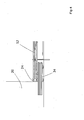
- FIGS 7 to 11 show the connection between the anchor 22 and the barrier rail 12 in more detail.
- the rail 12 connects to the second upright 24 via a bracket 50 shown separately in figures 9 to 11, figure 9 being a view along the direction of arrow IX in figure 10 .
- This has an C-section 52 comprising a vertical backplate 54 and upper and lower plates 56, 58 (respectively).
- On the rear of the backplate 54 i.e. extending in the opposite direction to the upper and lower plates 56, 58), a trapezoidal section 60 is attached to the C-section 52.
- This is a generally box-shaped section albeit with one side narrower than the opposing side.
- the sides connecting these are (in this example) non-parallel. It is attached to the backplate 54 via one of the non-parallel sides, with the edge between that side and the longer parallel side aligned with the open edge of the backplate 54.
- the remaining open edge of the C-section 52 is chamfered along a line that is generally aligned with the remaining non-parallel side of the trapezoidal section 60.
- the backplate 54 is essentially cut short and the upper and lowerplates 56, 58 have triangular extensions.
- the space thus created adjacent the backplate 54 is closed off with a connection plate 62.
- Figures 7 and 8 show how the bracket is fitted.
- the connection plate 62 is attached to the second upright 24 at the level of the rail 12, with the C-section 52 extending back along the path of the rail 12.
- the size of the C-section 52 corresponds to that of the reinforcement 34 behind the rail 12 such that the C-section 52 fits outside the reinforcement and can be connected to it by welding, bolting, etc. This connects the rail 12 (via the reinforcement 34) to the second upright 24.
- the trapezoidal section 60 is then located between the reinforcement 34 and the bracing structure 28, as the chamfer to the C-section 52 is aligned with the edge of the trapezoid. A small clearance may exist between them of, say 2-15mm.
- the rail 12 and reinforcement 34 are likely to be subject to forces tending to cause rotation at the point where they are connected to the anchor 21. If unconstrained, this rotation will allow the rail 12 to buckle and allow the vehicle to escape too far from the roadway.
- the above-described trapezoidal section 60 will then be trapped between the reinforcement 34 and the bracing structure 28, and will serve to constrain the reinforcement 34 and hence the rail 12 against further rotation.
- the degree of resistance offered by the trapezoidal section 60 can be tailored by adjusting the wall thickness, material strength, precise wall shapes, section profile, etc.
- Figure 12 shows a slightly modified bracket 50'. It differs in that the trapezoidal spacer 60' is solid instead of being hollow in section. This means that the spacer will be correspondingly less willing to deform under an impact, causing the bracket to offer greater resistance to rotational forces in the rail. In this way, and/or by changing the cross-sectional shape of the bracket, the action of the anchor under impact can be tailored to the requirements of the intended installation site.
Landscapes
- Engineering & Computer Science (AREA)
- Architecture (AREA)
- Civil Engineering (AREA)
- Structural Engineering (AREA)
- Refuge Islands, Traffic Blockers, Or Guard Fence (AREA)
Claims (10)
- Fahrzeugsicherheitsbarriere (10), einen Plankenabschnitt (12) aufweisend, der von Ständern (14) gestützt wird, und am Ende der Planke (12) und damit verbunden einen Anker (21), der erste und zweite Pfosten (22, 24) aufweist, wobei der Anker (21) hinter der Linie angeordnet ist, die von der Planke (12) definiert wird, wobei eine Versteifung (28) zwischen den ersten und zweiten Pfosten (22, 24) vorgesehen ist, und wobei das Ende der Planke (12) in Bezug auf die Ständer (22, 24) einwärts abgewinkelt ist, wobei sich die Planke (12) am ersten Pfosten (22) vorbei bis zu einem Verbindungspunkt mit dem zweiten Pfosten (24) erstreckt,
dadurch gekennzeichnet, dass der Anker so orientiert ist, dass sich die Linie, die von den ersten und zweiten Pfosten (22, 24) definiert wird, vom Ende der Planke (12) rückwärts zu den Ständern (14) der Planke (12) erstreckt und in einem spitzen Winkel zu der Linie verläuft, die von den Ständern (14) definiert wird, wobei dieser spitze Winkel in der Fläche gemessen wird, der von den Ständern (14) der Planke (12) und den Pfosten (22, 24) des Ankers (21) gebildet wird. - Fahrzeugsicherheitsbarriere nach Anspruch 1, wobei die Versteifung (28) mindestens eine schräge Strebe umfasst, die sich zwischen den Pfosten (22, 24) erstreckt.
- Fahrzeugsicherheitsbarriere nach Anspruch 2, wobei sich die schräge Strebe vom ersten Pfosten (22) zum zweiten Pfosten (24) aufwärts erstreckt.
- Fahrzeugsicherheitsbarriere nach einem der vorangehenden Ansprüche, wobei ein Pfosten (22, 24) mit einer Halterung (50) versehen ist, die an der Barriereplanke (12) befestigt ist, wobei die Halterung (50) eine Befestigungseinrichtung (52) zur Aufnahme der Planke (12) in einem spitzen Winkel zum Anker (21) und ein Distanzstück (60) zwischen der Planke (12) und dem Anker (21) aufweist.
- Fahrzeugsicherheitsbarriere nach Anspruch 4, wobei das Distanzstück (60) ein Hohlprofil ist.
- Fahrzeugsicherheitsbarriere nach Anspruch 4, wobei das Distanzstück (60) ein Vollprofil ist.
- Fahrzeugsicherheitsbarriere nach einem der Ansprüche 4 bis 6, wobei das Distanzstück (60) von trapezförmigem Querschnitt ist.
- Fahrzeugsicherheitsbarriere nach einem der Ansprüche 4 bis 7, wobei das Distanzstück (60) zwischen der Planke (12) und der Versteifung (28) angeordnet ist.
- Fahrzeugsicherheitsbarriere nach einem der Ansprüche 4 bis 8, wobei sich ein Teil der Befestigungseinrichtung (52) zwischen dem Distanzstück (60) und der Planke (12) erstreckt.
- Fahrzeugsicherheitsbarriere nach einem der vorangehenden Ansprüche, wobei sich ein Träger von der Planke (12) zum Anker (21) und zum Boden erstreckt.
Applications Claiming Priority (2)
| Application Number | Priority Date | Filing Date | Title |
|---|---|---|---|
| GB0611629A GB2439081A (en) | 2006-06-13 | 2006-06-13 | Vehicle safety barrier with angled anchor construction |
| PCT/EP2007/005173 WO2007144141A1 (en) | 2006-06-13 | 2007-06-12 | Vehicle safety barriers |
Publications (2)
| Publication Number | Publication Date |
|---|---|
| EP2032765A1 EP2032765A1 (de) | 2009-03-11 |
| EP2032765B1 true EP2032765B1 (de) | 2014-04-02 |
Family
ID=36745766
Family Applications (1)
| Application Number | Title | Priority Date | Filing Date |
|---|---|---|---|
| EP07725982.8A Not-in-force EP2032765B1 (de) | 2006-06-13 | 2007-06-12 | Fahrzeugsicherheitsbarrieren |
Country Status (3)
| Country | Link |
|---|---|
| EP (1) | EP2032765B1 (de) |
| GB (1) | GB2439081A (de) |
| WO (1) | WO2007144141A1 (de) |
Families Citing this family (1)
| Publication number | Priority date | Publication date | Assignee | Title |
|---|---|---|---|---|
| HRP20250013T1 (hr) * | 2020-05-29 | 2025-03-14 | Pasquale Impero | Modularna cestovna sigurnosna pregrada i prolaz koji se može otvoriti u slučaju nužde |
Family Cites Families (9)
| Publication number | Priority date | Publication date | Assignee | Title |
|---|---|---|---|---|
| US1966778A (en) * | 1933-09-05 | 1934-07-17 | Jr Robert J Woods | Road guard for highways |
| US2146445A (en) * | 1937-04-16 | 1939-02-07 | Mullins Mfg Corp | End post construction for highway guardrails and the like |
| US4678166A (en) * | 1986-04-24 | 1987-07-07 | Southwest Research Institute | Eccentric loader guardrail terminal |
| US6220575B1 (en) * | 1995-01-18 | 2001-04-24 | Trn Business Trust | Anchor assembly for highway guardrail end terminal |
| US5765811A (en) * | 1997-03-18 | 1998-06-16 | Alberson; Dean C. | Guardrail terminal |
| US5967497A (en) * | 1997-12-15 | 1999-10-19 | Energy Absorption Systems, Inc. | Highway barrier and guardrail |
| US6783116B2 (en) * | 1999-01-06 | 2004-08-31 | Trn Business Trust | Guardrail end terminal assembly having at least one angle strut |
| DE10231903B4 (de) * | 2002-07-11 | 2005-02-03 | Outimex-Bautechnik Gmbh | Leitelement für den Anfangs- oder Endbereich einer Leitplanke oder eines Leitplankensystems an Verkehrswegen |
| ITTO20020620A1 (it) * | 2002-07-16 | 2004-01-16 | Fracasso Metalmeccanica | Terminale di barriera stradale |
-
2006
- 2006-06-13 GB GB0611629A patent/GB2439081A/en not_active Withdrawn
-
2007
- 2007-06-12 EP EP07725982.8A patent/EP2032765B1/de not_active Not-in-force
- 2007-06-12 WO PCT/EP2007/005173 patent/WO2007144141A1/en not_active Ceased
Also Published As
| Publication number | Publication date |
|---|---|
| EP2032765A1 (de) | 2009-03-11 |
| GB0611629D0 (en) | 2006-07-19 |
| GB2439081A (en) | 2007-12-19 |
| WO2007144141A1 (en) | 2007-12-21 |
Similar Documents
| Publication | Publication Date | Title |
|---|---|---|
| US8157471B2 (en) | Combined guardrail and cable safety systems | |
| US6854716B2 (en) | Crash cushions and other energy absorbing devices | |
| US6129342A (en) | Guardrail end terminal for side or front impact and method | |
| EP1540086B1 (de) | Aufgeweitetes Energieabsorptionssystem | |
| US7104720B2 (en) | Traffic noise barrier system | |
| US7059590B2 (en) | Impact assembly for an energy absorbing device | |
| AU2054599A (en) | Safety barrier terminal for motorway guard-rail | |
| CN103526705A (zh) | 用于耗散能量以使撞击车辆减速的护栏安全系统 | |
| GB2023695A (en) | Crash barriers | |
| US5348416A (en) | Gandy dancer: end piece for crash cushion or rail end treatment | |
| EP2032765B1 (de) | Fahrzeugsicherheitsbarrieren | |
| US11891765B2 (en) | Barrier transition framework | |
| WO2007144656A1 (en) | Vehicle safety barriers | |
| JP2004156426A (ja) | ガードレールの衝撃吸収構造体 | |
| CA3116000A1 (en) | Deflector bracket and cable anchor for guardrail terminal | |
| KR102809265B1 (ko) | 차량 충격흡수장치 | |
| MXPA06006590A (es) | Sistema de seguridad de atenuacion de energia. | |
| KR101181429B1 (ko) | 충격흡수가드레일 | |
| AU2023233067A1 (en) | Barrier transition framework | |
| US20050092977A1 (en) | Crash cushion and method of utilizing a crash cushion | |
| WO2007144142A1 (en) | Rail for vehicle safety barriers | |
| EP1927700A1 (de) | Sicherheitsbarrieren für Fahrzeuge | |
| MXPA99007794A (en) | Safety barrier terminal for motorway guard-rail |
Legal Events
| Date | Code | Title | Description |
|---|---|---|---|
| PUAI | Public reference made under article 153(3) epc to a published international application that has entered the european phase |
Free format text: ORIGINAL CODE: 0009012 |
|
| 17P | Request for examination filed |
Effective date: 20090113 |
|
| AK | Designated contracting states |
Kind code of ref document: A1 Designated state(s): AT BE BG CH CY CZ DE DK EE ES FI FR GB GR HU IE IS IT LI LT LU LV MC MT NL PL PT RO SE SI SK TR |
|
| AX | Request for extension of the european patent |
Extension state: AL BA HR MK RS |
|
| 17Q | First examination report despatched |
Effective date: 20100719 |
|
| RAP1 | Party data changed (applicant data changed or rights of an application transferred) |
Owner name: TATA STEEL UK LIMITED |
|
| DAX | Request for extension of the european patent (deleted) | ||
| GRAP | Despatch of communication of intention to grant a patent |
Free format text: ORIGINAL CODE: EPIDOSNIGR1 |
|
| INTG | Intention to grant announced |
Effective date: 20131021 |
|
| GRAS | Grant fee paid |
Free format text: ORIGINAL CODE: EPIDOSNIGR3 |
|
| GRAA | (expected) grant |
Free format text: ORIGINAL CODE: 0009210 |
|
| RAP1 | Party data changed (applicant data changed or rights of an application transferred) |
Owner name: TATA STEEL UK LIMITED |
|
| AK | Designated contracting states |
Kind code of ref document: B1 Designated state(s): AT BE BG CH CY CZ DE DK EE ES FI FR GB GR HU IE IS IT LI LT LU LV MC MT NL PL PT RO SE SI SK TR |
|
| REG | Reference to a national code |
Ref country code: GB Ref legal event code: FG4D |
|
| REG | Reference to a national code |
Ref country code: AT Ref legal event code: REF Ref document number: 660249 Country of ref document: AT Kind code of ref document: T Effective date: 20140415 Ref country code: CH Ref legal event code: EP |
|
| REG | Reference to a national code |
Ref country code: IE Ref legal event code: FG4D |
|
| REG | Reference to a national code |
Ref country code: DE Ref legal event code: R096 Ref document number: 602007035884 Country of ref document: DE Effective date: 20140515 |
|
| REG | Reference to a national code |
Ref country code: NL Ref legal event code: T3 |
|
| REG | Reference to a national code |
Ref country code: AT Ref legal event code: MK05 Ref document number: 660249 Country of ref document: AT Kind code of ref document: T Effective date: 20140402 |
|
| REG | Reference to a national code |
Ref country code: LT Ref legal event code: MG4D |
|
| PG25 | Lapsed in a contracting state [announced via postgrant information from national office to epo] |
Ref country code: CY Free format text: LAPSE BECAUSE OF FAILURE TO SUBMIT A TRANSLATION OF THE DESCRIPTION OR TO PAY THE FEE WITHIN THE PRESCRIBED TIME-LIMIT Effective date: 20140402 Ref country code: IS Free format text: LAPSE BECAUSE OF FAILURE TO SUBMIT A TRANSLATION OF THE DESCRIPTION OR TO PAY THE FEE WITHIN THE PRESCRIBED TIME-LIMIT Effective date: 20140802 Ref country code: LT Free format text: LAPSE BECAUSE OF FAILURE TO SUBMIT A TRANSLATION OF THE DESCRIPTION OR TO PAY THE FEE WITHIN THE PRESCRIBED TIME-LIMIT Effective date: 20140402 Ref country code: BG Free format text: LAPSE BECAUSE OF FAILURE TO SUBMIT A TRANSLATION OF THE DESCRIPTION OR TO PAY THE FEE WITHIN THE PRESCRIBED TIME-LIMIT Effective date: 20140702 Ref country code: CZ Free format text: LAPSE BECAUSE OF FAILURE TO SUBMIT A TRANSLATION OF THE DESCRIPTION OR TO PAY THE FEE WITHIN THE PRESCRIBED TIME-LIMIT Effective date: 20140402 Ref country code: GR Free format text: LAPSE BECAUSE OF FAILURE TO SUBMIT A TRANSLATION OF THE DESCRIPTION OR TO PAY THE FEE WITHIN THE PRESCRIBED TIME-LIMIT Effective date: 20140703 Ref country code: FI Free format text: LAPSE BECAUSE OF FAILURE TO SUBMIT A TRANSLATION OF THE DESCRIPTION OR TO PAY THE FEE WITHIN THE PRESCRIBED TIME-LIMIT Effective date: 20140402 |
|
| PG25 | Lapsed in a contracting state [announced via postgrant information from national office to epo] |
Ref country code: ES Free format text: LAPSE BECAUSE OF FAILURE TO SUBMIT A TRANSLATION OF THE DESCRIPTION OR TO PAY THE FEE WITHIN THE PRESCRIBED TIME-LIMIT Effective date: 20140402 Ref country code: SE Free format text: LAPSE BECAUSE OF FAILURE TO SUBMIT A TRANSLATION OF THE DESCRIPTION OR TO PAY THE FEE WITHIN THE PRESCRIBED TIME-LIMIT Effective date: 20140402 Ref country code: LV Free format text: LAPSE BECAUSE OF FAILURE TO SUBMIT A TRANSLATION OF THE DESCRIPTION OR TO PAY THE FEE WITHIN THE PRESCRIBED TIME-LIMIT Effective date: 20140402 Ref country code: PL Free format text: LAPSE BECAUSE OF FAILURE TO SUBMIT A TRANSLATION OF THE DESCRIPTION OR TO PAY THE FEE WITHIN THE PRESCRIBED TIME-LIMIT Effective date: 20140402 Ref country code: AT Free format text: LAPSE BECAUSE OF FAILURE TO SUBMIT A TRANSLATION OF THE DESCRIPTION OR TO PAY THE FEE WITHIN THE PRESCRIBED TIME-LIMIT Effective date: 20140402 |
|
| PG25 | Lapsed in a contracting state [announced via postgrant information from national office to epo] |
Ref country code: PT Free format text: LAPSE BECAUSE OF FAILURE TO SUBMIT A TRANSLATION OF THE DESCRIPTION OR TO PAY THE FEE WITHIN THE PRESCRIBED TIME-LIMIT Effective date: 20140804 |
|
| REG | Reference to a national code |
Ref country code: DE Ref legal event code: R119 Ref document number: 602007035884 Country of ref document: DE |
|
| PG25 | Lapsed in a contracting state [announced via postgrant information from national office to epo] |
Ref country code: SK Free format text: LAPSE BECAUSE OF FAILURE TO SUBMIT A TRANSLATION OF THE DESCRIPTION OR TO PAY THE FEE WITHIN THE PRESCRIBED TIME-LIMIT Effective date: 20140402 Ref country code: DK Free format text: LAPSE BECAUSE OF FAILURE TO SUBMIT A TRANSLATION OF THE DESCRIPTION OR TO PAY THE FEE WITHIN THE PRESCRIBED TIME-LIMIT Effective date: 20140402 Ref country code: EE Free format text: LAPSE BECAUSE OF FAILURE TO SUBMIT A TRANSLATION OF THE DESCRIPTION OR TO PAY THE FEE WITHIN THE PRESCRIBED TIME-LIMIT Effective date: 20140402 Ref country code: LU Free format text: LAPSE BECAUSE OF FAILURE TO SUBMIT A TRANSLATION OF THE DESCRIPTION OR TO PAY THE FEE WITHIN THE PRESCRIBED TIME-LIMIT Effective date: 20140612 Ref country code: BE Free format text: LAPSE BECAUSE OF FAILURE TO SUBMIT A TRANSLATION OF THE DESCRIPTION OR TO PAY THE FEE WITHIN THE PRESCRIBED TIME-LIMIT Effective date: 20140402 Ref country code: RO Free format text: LAPSE BECAUSE OF FAILURE TO SUBMIT A TRANSLATION OF THE DESCRIPTION OR TO PAY THE FEE WITHIN THE PRESCRIBED TIME-LIMIT Effective date: 20140402 Ref country code: MC Free format text: LAPSE BECAUSE OF FAILURE TO SUBMIT A TRANSLATION OF THE DESCRIPTION OR TO PAY THE FEE WITHIN THE PRESCRIBED TIME-LIMIT Effective date: 20140402 |
|
| REG | Reference to a national code |
Ref country code: CH Ref legal event code: PL |
|
| PLBE | No opposition filed within time limit |
Free format text: ORIGINAL CODE: 0009261 |
|
| STAA | Information on the status of an ep patent application or granted ep patent |
Free format text: STATUS: NO OPPOSITION FILED WITHIN TIME LIMIT |
|
| 26N | No opposition filed |
Effective date: 20150106 |
|
| REG | Reference to a national code |
Ref country code: FR Ref legal event code: ST Effective date: 20150227 |
|
| PG25 | Lapsed in a contracting state [announced via postgrant information from national office to epo] |
Ref country code: IT Free format text: LAPSE BECAUSE OF FAILURE TO SUBMIT A TRANSLATION OF THE DESCRIPTION OR TO PAY THE FEE WITHIN THE PRESCRIBED TIME-LIMIT Effective date: 20140402 |
|
| REG | Reference to a national code |
Ref country code: DE Ref legal event code: R119 Ref document number: 602007035884 Country of ref document: DE Effective date: 20150101 |
|
| PG25 | Lapsed in a contracting state [announced via postgrant information from national office to epo] |
Ref country code: DE Free format text: LAPSE BECAUSE OF NON-PAYMENT OF DUE FEES Effective date: 20150101 Ref country code: LI Free format text: LAPSE BECAUSE OF NON-PAYMENT OF DUE FEES Effective date: 20140630 Ref country code: CH Free format text: LAPSE BECAUSE OF NON-PAYMENT OF DUE FEES Effective date: 20140630 |
|
| PG25 | Lapsed in a contracting state [announced via postgrant information from national office to epo] |
Ref country code: FR Free format text: LAPSE BECAUSE OF NON-PAYMENT OF DUE FEES Effective date: 20140630 |
|
| PG25 | Lapsed in a contracting state [announced via postgrant information from national office to epo] |
Ref country code: SI Free format text: LAPSE BECAUSE OF FAILURE TO SUBMIT A TRANSLATION OF THE DESCRIPTION OR TO PAY THE FEE WITHIN THE PRESCRIBED TIME-LIMIT Effective date: 20140402 |
|
| PGFP | Annual fee paid to national office [announced via postgrant information from national office to epo] |
Ref country code: GB Payment date: 20150629 Year of fee payment: 9 |
|
| PGFP | Annual fee paid to national office [announced via postgrant information from national office to epo] |
Ref country code: IE Payment date: 20150630 Year of fee payment: 9 Ref country code: NL Payment date: 20150626 Year of fee payment: 9 |
|
| PG25 | Lapsed in a contracting state [announced via postgrant information from national office to epo] |
Ref country code: MT Free format text: LAPSE BECAUSE OF FAILURE TO SUBMIT A TRANSLATION OF THE DESCRIPTION OR TO PAY THE FEE WITHIN THE PRESCRIBED TIME-LIMIT Effective date: 20140402 |
|
| PG25 | Lapsed in a contracting state [announced via postgrant information from national office to epo] |
Ref country code: TR Free format text: LAPSE BECAUSE OF FAILURE TO SUBMIT A TRANSLATION OF THE DESCRIPTION OR TO PAY THE FEE WITHIN THE PRESCRIBED TIME-LIMIT Effective date: 20140402 Ref country code: HU Free format text: LAPSE BECAUSE OF FAILURE TO SUBMIT A TRANSLATION OF THE DESCRIPTION OR TO PAY THE FEE WITHIN THE PRESCRIBED TIME-LIMIT; INVALID AB INITIO Effective date: 20070612 |
|
| REG | Reference to a national code |
Ref country code: NL Ref legal event code: MM Effective date: 20160701 |
|
| GBPC | Gb: european patent ceased through non-payment of renewal fee |
Effective date: 20160612 |
|
| REG | Reference to a national code |
Ref country code: IE Ref legal event code: MM4A |
|
| PG25 | Lapsed in a contracting state [announced via postgrant information from national office to epo] |
Ref country code: IE Free format text: LAPSE BECAUSE OF NON-PAYMENT OF DUE FEES Effective date: 20160612 Ref country code: NL Free format text: LAPSE BECAUSE OF NON-PAYMENT OF DUE FEES Effective date: 20160701 Ref country code: GB Free format text: LAPSE BECAUSE OF NON-PAYMENT OF DUE FEES Effective date: 20160612 |