EP2042787A2 - Bauteileanordnung - Google Patents
Bauteileanordnung Download PDFInfo
- Publication number
- EP2042787A2 EP2042787A2 EP08104878A EP08104878A EP2042787A2 EP 2042787 A2 EP2042787 A2 EP 2042787A2 EP 08104878 A EP08104878 A EP 08104878A EP 08104878 A EP08104878 A EP 08104878A EP 2042787 A2 EP2042787 A2 EP 2042787A2
- Authority
- EP
- European Patent Office
- Prior art keywords
- component
- sealing element
- housing
- arrangement according
- sealing
- Prior art date
- Legal status (The legal status is an assumption and is not a legal conclusion. Google has not performed a legal analysis and makes no representation as to the accuracy of the status listed.)
- Withdrawn
Links
- 238000007789 sealing Methods 0.000 claims abstract description 51
- 239000000853 adhesive Substances 0.000 claims abstract description 16
- 230000001070 adhesive effect Effects 0.000 claims abstract description 16
- 239000003822 epoxy resin Substances 0.000 claims abstract description 9
- 229920000647 polyepoxide Polymers 0.000 claims abstract description 9
- 229920001296 polysiloxane Polymers 0.000 claims abstract description 7
- 238000004382 potting Methods 0.000 claims description 8
- 150000001875 compounds Chemical class 0.000 claims description 4
- 238000010276 construction Methods 0.000 abstract 1
- 239000004033 plastic Substances 0.000 description 3
- 229920003023 plastic Polymers 0.000 description 3
- 239000000126 substance Substances 0.000 description 3
- 239000004593 Epoxy Substances 0.000 description 2
- 238000004026 adhesive bonding Methods 0.000 description 2
- 239000004020 conductor Substances 0.000 description 2
- 239000000463 material Substances 0.000 description 2
- 239000002184 metal Substances 0.000 description 2
- 229910052751 metal Inorganic materials 0.000 description 2
- 238000000034 method Methods 0.000 description 2
- XLYOFNOQVPJJNP-UHFFFAOYSA-N water Substances O XLYOFNOQVPJJNP-UHFFFAOYSA-N 0.000 description 2
- 239000004823 Reactive adhesive Substances 0.000 description 1
- 230000004913 activation Effects 0.000 description 1
- 239000012790 adhesive layer Substances 0.000 description 1
- 230000032683 aging Effects 0.000 description 1
- 230000000712 assembly Effects 0.000 description 1
- 238000000429 assembly Methods 0.000 description 1
- 239000000919 ceramic Substances 0.000 description 1
- 238000004140 cleaning Methods 0.000 description 1
- 238000010924 continuous production Methods 0.000 description 1
- 238000005516 engineering process Methods 0.000 description 1
- 230000007613 environmental effect Effects 0.000 description 1
- 229920006334 epoxy coating Polymers 0.000 description 1
- 238000003780 insertion Methods 0.000 description 1
- 230000037431 insertion Effects 0.000 description 1
- 238000005304 joining Methods 0.000 description 1
- 239000010410 layer Substances 0.000 description 1
- 230000007774 longterm Effects 0.000 description 1
- 238000004519 manufacturing process Methods 0.000 description 1
- 150000002739 metals Chemical class 0.000 description 1
- 230000000149 penetrating effect Effects 0.000 description 1
- 229920002635 polyurethane Polymers 0.000 description 1
- 239000004814 polyurethane Substances 0.000 description 1
- 238000007788 roughening Methods 0.000 description 1
- 239000013464 silicone adhesive Substances 0.000 description 1
- 239000002904 solvent Substances 0.000 description 1
- 230000000087 stabilizing effect Effects 0.000 description 1
- 230000035882 stress Effects 0.000 description 1
Images

Classifications
-
- F—MECHANICAL ENGINEERING; LIGHTING; HEATING; WEAPONS; BLASTING
- F16—ENGINEERING ELEMENTS AND UNITS; GENERAL MEASURES FOR PRODUCING AND MAINTAINING EFFECTIVE FUNCTIONING OF MACHINES OR INSTALLATIONS; THERMAL INSULATION IN GENERAL
- F16J—PISTONS; CYLINDERS; SEALINGS
- F16J15/00—Sealings
- F16J15/16—Sealings between relatively-moving surfaces
- F16J15/32—Sealings between relatively-moving surfaces with elastic sealings, e.g. O-rings
- F16J15/3204—Sealings between relatively-moving surfaces with elastic sealings, e.g. O-rings with at least one lip
- F16J15/3232—Sealings between relatively-moving surfaces with elastic sealings, e.g. O-rings with at least one lip having two or more lips
-
- F—MECHANICAL ENGINEERING; LIGHTING; HEATING; WEAPONS; BLASTING
- F16—ENGINEERING ELEMENTS AND UNITS; GENERAL MEASURES FOR PRODUCING AND MAINTAINING EFFECTIVE FUNCTIONING OF MACHINES OR INSTALLATIONS; THERMAL INSULATION IN GENERAL
- F16J—PISTONS; CYLINDERS; SEALINGS
- F16J15/00—Sealings
- F16J15/02—Sealings between relatively-stationary surfaces
- F16J15/06—Sealings between relatively-stationary surfaces with solid packing compressed between sealing surfaces
- F16J15/061—Sealings between relatively-stationary surfaces with solid packing compressed between sealing surfaces with positioning means
-
- F—MECHANICAL ENGINEERING; LIGHTING; HEATING; WEAPONS; BLASTING
- F16—ENGINEERING ELEMENTS AND UNITS; GENERAL MEASURES FOR PRODUCING AND MAINTAINING EFFECTIVE FUNCTIONING OF MACHINES OR INSTALLATIONS; THERMAL INSULATION IN GENERAL
- F16J—PISTONS; CYLINDERS; SEALINGS
- F16J15/00—Sealings
- F16J15/16—Sealings between relatively-moving surfaces
- F16J15/32—Sealings between relatively-moving surfaces with elastic sealings, e.g. O-rings
- F16J15/3268—Mounting of sealing rings
- F16J15/3276—Mounting of sealing rings with additional static sealing between the sealing, or its casing or support, and the surface on which it is mounted
-
- H—ELECTRICITY
- H01—ELECTRIC ELEMENTS
- H01R—ELECTRICALLY-CONDUCTIVE CONNECTIONS; STRUCTURAL ASSOCIATIONS OF A PLURALITY OF MUTUALLY-INSULATED ELECTRICAL CONNECTING ELEMENTS; COUPLING DEVICES; CURRENT COLLECTORS
- H01R13/00—Details of coupling devices of the kinds covered by groups H01R12/70 or H01R24/00 - H01R33/00
- H01R13/46—Bases; Cases
- H01R13/52—Dustproof, splashproof, drip-proof, waterproof, or flameproof cases
- H01R13/5205—Sealing means between cable and housing, e.g. grommet
-
- H—ELECTRICITY
- H01—ELECTRIC ELEMENTS
- H01R—ELECTRICALLY-CONDUCTIVE CONNECTIONS; STRUCTURAL ASSOCIATIONS OF A PLURALITY OF MUTUALLY-INSULATED ELECTRICAL CONNECTING ELEMENTS; COUPLING DEVICES; CURRENT COLLECTORS
- H01R13/00—Details of coupling devices of the kinds covered by groups H01R12/70 or H01R24/00 - H01R33/00
- H01R13/46—Bases; Cases
- H01R13/52—Dustproof, splashproof, drip-proof, waterproof, or flameproof cases
- H01R13/5216—Dustproof, splashproof, drip-proof, waterproof, or flameproof cases characterised by the sealing material, e.g. gels or resins
Definitions
- the invention relates to a component assembly according to the preamble of the independent claim.
- sealing elements of vulcanised silicone are known, for example for cable bushings.
- Epoxy resin is known as potting for the protection of electrical components, for example in relays or ignition coils of motor vehicles.
- these known types of seals are not always satisfactory and have temperature-related or aging-related leaks, especially at strongly changing operating conditions, such as occur in motor vehicles, for example.
- the component assembly according to the invention with the features of the independent claim has the advantage that a largely temperature-independent, long-term resistant sealing of the component assembly is achieved by bonding the sealing element with one or more adjacent components.
- epoxy resin has proven to be advantageous as an adhesive, wherein the surface of the sealing element and / or an adjacent component is expediently pretreated to improve the adhesion in order to achieve a particularly secure and tight bonding.
- Particularly advantageous in this case is the pretreatment of the surface of the sealing element and / or the housing by an atmospheric plasma.
- the sealing element is elastically deformed in the installed state and is under mechanical bias, in particular with respect to the output part of the functional component.
- a particularly good sealing is achieved in this case when the sealing element has an elastically deformable sealing contour, in particular one or more sealing lips.
- an insert is integrated in the sealing element for stabilizing the shape.
- the component assembly according to the invention has proven particularly useful when an electronic control unit and as an output part of the functional component to seal an electrical connection line, since in such components on the one hand the requirements for the seal very high, but on the other hand are difficult to meet, as they are often even in the Generate heat and are particularly sensitive to the ingress of moisture.
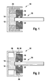
- FIG. 1 10 denotes a component arrangement which accommodates a functional component 14 in the form of an electric motor in a housing 12.
- the output part 16 this has a slowly or intermittently rotating drive shaft, which is sealed by an annular sealing member 18 against environmental influences introduced into the housing 12.
- the output part 16 is enclosed gap-free by two circumferential sealing lips 22 and 24 on the sealing element 18 and the sealing member 18 in turn by Epoxidharzverguss 20 tightly and firmly bonded to the housing 12 and the functional component 14.
- the sealing element 18 is made of elastic, vulcanized silicone. When installed, it is elastically deformed and is under mechanical bias to the output part 16, so that along the output part no moisture or dirt can penetrate.
- the sealing element 18 is connected by the Epoxidharzverguss 20 tightly connected to the housing 12, preferably all of the surfaces to be wetted by the Epoxidharzverguss 20 of the sealing member 18, the housing 12 and the functional component 14 are pretreated adhesion improving.
- the adhesive technology in production is improved in terms of precision and speed.
- Reactive adhesives preferably epoxy resin adhesives, which can be applied both as a layer or as a potting compound, are particularly suitable for bonding.
- epoxy resin adhesives preferably epoxy resin adhesives
- polyurethane adhesives or Silicone adhesives are used, which are also applied layered or as a potting.
- reaction adhesives and solvent-containing adhesives are used instead of the aforementioned reaction adhesives and solvent-containing adhesives.
- a plasma pretreatment is particularly suitable as a physical-chemical surface pretreatment of plastics and metals, at the same time a cleaning and activation of the component surface is achieved.
- the methods themselves are basically known and therefore need not be discussed further here. Instead of the physical-chemical pretreatment by a plasma, however, a purely mechanical or chemical pretreatment is applicable.
- FIG. 2 shows a component assembly 10, in which the functional component 14 is attached to the housing 12 independent of the seal.
- the functional component 14 itself and its output part 16 are of the same design as in FIG FIG. 1 , as well as the sealing element 18.
- the housing according to FIG. 2 a radially projecting edge 26 on which the sealing element 18 rests laterally without gluing.
- the seal is made by an adhesive 28 between the Seal member 18 on the one hand and the housing shell 30 and the adjacent portion of the housing edge 26 on the other.
- the adhesive 28 may in this case in turn be introduced as a potting or as an adhesive layer, which is applied to the housing shell 30 before the introduction of the sealing element 18.
- the elastic sealing element 18 is radially compressed before insertion and only in the housing 12 relaxed.
- the seal between the output part 16 and the sealing member 18 corresponds to the in FIG. 1 explained way.
- FIG. 3 shows a component assembly 10, wherein from the housing 12, only an intermediate wall 32 is visible, on the left side as a functional component 14, an electronic control unit 34 is attached, protrude from the two contact lugs 36 and 38 through the intermediate wall 32 into the Epoxidharzverguss 20.
- output parts 16 in this case on the one hand to the contact lug 36 connected conductor strip 40 and on the other hand, a connected to the contact lug 38 insulated cable 42 are shown.
- the sealing of the housing 12 is not completely shown by two outer sealing elements 44 and 46 and a double-acting inner sealing element 48, wherein also here the sealing elements have lip-shaped sealing contours.
- an insert member 50 and in the outer sealing member 46 an insert 52 are inserted, which improve the rigidity of the sealing elements.
- the Einlegteil 52 wholly or partially takes over the function of the housing 12 or it is an integrated component of the housing.
- the inserts 50 and 52 can optionally consist of plastic or metal.
- the seal between the output parts 16 and the interior of the housing takes place in basically the same way as in the Figures 1 and 2 However, in this embodiment, however, are stationary output parts 16 which are fixedly connected to the contact lugs 36 and 38.
- the bonding of the sealing elements 44, 46 and 48 with the housing 12 is according to the embodiment in FIG. 1 in turn achieved by a Epoxidharzverguss 20, which simultaneously secures the locking of the contact lugs 36 and 38 and the ends of the conductor strip 40 and the cable 42.
- the component assemblies 10 according to the invention ensure a permanent seal, which in particular also meets the high requirements in the motor vehicle caused by severe temperature changes, in particular in the engine compartment of the motor vehicle.
- the elasticity of the sealing elements and an adhesive with good adhesion to the various components ensures the seal at all times, even with thermally induced mechanical stresses due to different expansion coefficients of the components.
- the preferred material combination of epoxy resin and vulcanized silicone ensures this the desired elasticity and the adhesive force, with epoxy as an adhesive ensures a particularly good adhesion in particular to plastic and ceramic.
- the vulcanized silicone material used also seals well when vibrations occur at the output parts 16 and acts there as a decoupling element for the vibrations occurring.
Landscapes
- Engineering & Computer Science (AREA)
- General Engineering & Computer Science (AREA)
- Mechanical Engineering (AREA)
- Chemical & Material Sciences (AREA)
- Dispersion Chemistry (AREA)
- Casings For Electric Apparatus (AREA)
- Motor Or Generator Frames (AREA)
- Structures Or Materials For Encapsulating Or Coating Semiconductor Devices Or Solid State Devices (AREA)
Abstract
Description
- Die Erfindung geht aus von einer Bauteileanordnung nach der Gattung des unabhängigen Anspruchs.
- Aus der
DE 100 81 007 T1 ist eine Bauteileanordnung mit einer Schaltvorrichtung in einem mehrteiligen Gehäuse bekannt, welche insbesondere gegenüber eindringendem Wasser durch ein Dichtungselement aus vulkanisiertem Silikon geschützt ist. Alternativ ist in dieser Druckschrift darauf hingewiesen, dass freiliegende Schaltungsteile innerhalb des Gehäuses durch Epoxid-Beschichtungen wasserbeständig geschützt werden können. Hinweise auf die Möglichkeit des Verklebens eines Dichtungselementes mit einzelnen Komponenten der Bauteileanordnung enthält die Druckschrift nicht. - Darüber hinaus sind im allgemeinen Stand der Technik Dichtungselemente aus vulkanisiertem Silikon bekannt, beispielsweise für Kabeldurchführungen. Epoxidharz ist als Verguss zum Schutz von elektrischen Bauelementen bekannt, beispielsweise in Relais oder Zündspulen von Kraftfahrzeugen. Diese bekannten Dichtungsarten sind jedoch nicht immer befriedigend und weisen temperaturbedingte oder alterungsbedingte Undichtigkeiten auf, insbesondere bei stark wechselnden Betriebsbedingungen, wie sie beispielsweise in Kraftfahrzeugen auftreten.
- Die erfindungsgemäße Bauteileanordnung mit den Merkmalen des unabhängigen Anspruchs hat demgegenüber den Vorteil, dass durch das Verkleben des Dichtungselementes mit einem oder mehreren angrenzenden Bauteilen eine weitestgehend temperaturunabhängige, langzeitbeständige Abdichtung der Bauteileanordnung erreicht wird. Als Klebemittel hat sich hierbei insbesondere Epoxidharz als vorteilhaft erwiesen, wobei zweckmäßigerweise zur Erzielung einer besonders sicheren und dichten Verklebung die Oberfläche des Dichtungselementes und/oder eines angrenzenden Bauteils, zur Haftungsverbesserung vorbehandelt wird. Besonders vorteilhaft ist hierbei die Vorbehandlung der Oberfläche des Dichtungselementes und/oder des Gehäuses durch ein Atmosphärenplasma.
- Zur Verbesserung der Abdichtung ist es weiterhin zweckmäßig, wenn das Dichtungselement im eingebauten Zustand elastisch verformt ist und unter mechanischer Vorspannung steht, insbesondere gegenüber dem Ausgangsteil der Funktionskomponente. Eine besonders gute Abdichtung erreicht man hierbei, wenn das Dichtungselement eine elastisch verformbare Dichtkontur, insbesondere eine oder mehrere Dichtlippen aufweist. Hierbei kann es weiterhin zweckmäßig sein, wenn in das Dichtungselement zur Formstabilisierung ein Einlegeteil integriert ist.
- Bei der Verwendung von Epoxidharz als Klebemittel zwischen dem Dichtungselement und benachbarten Bauteilen ist es zweckmäßig, das Epoxidharz als Vergussmasse oder Spritzmasse aufzubringen. Hierdurch wird verfahrenstechnisch sichergestellt, dass das Klebemittel ohne Fügeprobleme alle zu verklebenden Oberflächenabschnitte sicher erreicht und benetzt.
- Die erfindungsgemäße Bauteileanordnung hat sich besonders bewährt, wenn als Funktionskomponente ein elektronisches Steuergerät und als Ausgangsteil der Funktionskomponente eine elektrische Anschlussleitung abzudichten sind, da bei derartigen Bauteilen einerseits die Anforderungen an die Abdichtung sehr hoch, andererseits aber schwer zu erfüllen sind, da sie häufig selbst im Betrieb Wärme erzeugen und gegen eindringende Feuchtigkeit besonders empfindlich sind.
- Ausführungsbeispiele der Erfindung sind in den Zeichnungen dargestellt und in der nachfolgenden Beschreibung näher erläutert.
- Es zeigen
- Figur 1
- eine Bauteileanordnung, bei welcher eine Funktionskomponente und ein Dichtungselement durch eine Vergussmasse verklebt sind,
- Figur 2
- eine Bauteileanordnung, bei der ein Dichtungselement nur mit dem Gehäuse verklebt ist und
- Figur 3
- eine Bauteileanordnung mit Dichtungselementen, welche durch Vergussmasse mit anderen Bauteilen und mit dem Gehäuse verklebt sind.
- In
Figur 1 ist mit 10 eine Bauteileanordnung bezeichnet, welche in einem Gehäuse 12 eine Funktionskomponente 14 in Form eines Elektromotors aufnimmt. Als Ausgangsteil 16 besitzt dieser eine langsam oder intermittierend rotierende Antriebswelle, welche durch ein ringförmiges Dichtungselement 18 gegen Umgebungseinflüsse abgedichtet in das Gehäuse 12 eingeführt ist. Hierzu ist das Ausgangsteil 16 durch zwei umlaufende Dichtlippen 22 und 24 am Dichtungselement 18 spaltfrei umschlossen und das Dichtungselement 18 seinerseits durch Epoxidharzverguss 20 dicht und fest mit dem Gehäuse 12 und mit der Funktionskomponente 14 verklebt. - Das Dichtungselement 18 besteht aus elastischem, vulkanisiertem Silikon. Im eingebauten Zustand ist es elastisch verformt und steht unter mechanischer Vorspannung zu dem Ausgangsteil 16, so dass entlang des Ausgangsteils keine Feuchtigkeit oder Schmutz eindringen kann. Andererseits ist das Dichtungselement 18 durch den Epoxidharzverguss 20 dicht mit dem Gehäuse 12 verbunden, wobei vorzugsweise alle von dem Epoxidharzverguss 20 zu benetzenden Oberflächen des Dichtungselements 18, des Gehäuses 12 und der Funktionskomponente 14 haftungsverbessernd vorbehandelt sind. Hierdurch wird neben der Haftung selbst auch die Klebtechnik in der Fertigung hinsichtlich Präzision und Schnelligkeit verbessert.
- Zum Verkleben eignen sich insbesondere Reaktionsklebstoffe, vorzugsweise Epoxidharzklebstoffe, welche sowohl als Schicht aufgetragen oder als Verguss angewendet werden können. Neben Epoxidharz können jedoch auch Polyurethanklebstoffe oder Silikonklebstoffe verwendet werden, welche ebenfalls schichtförmig oder als Verguss aufgebracht werden. Anstelle der vorgenannten Reaktionsklebstoffe sind jedoch auch lösungsmittelhaltige Klebstoffe verwendbar.
- Wichtig für die Stärke der Adhäsionskräfte beim Verkleben der Bauteile ist die Beschaffenheit der jeweils zu verklebenden Oberflächen. Neben der bereits genannten Vorbehandlung der Oberflächen durch ein Atmosphärendruckplasma eignen sich zur Vorbehandlung auch andere Verfahren, welche eine Aufrauung der Oberfläche und damit eine bessere Verzahnung der Klebstoffmoleküle mit dem Fügeteil bewirken können. Die nächstliegende Alternative wäre ein Niederdruckplasma, welches jedoch in kontinuierlichen Prozessen schwieriger einsetzbar ist. Eine Plasmavorbehandlung eignet sich insbesondere als physikalisch-chemische Oberflächenvorbehandlung von Kunststoffen und Metallen, wobei gleichzeitig eine Reinigung und Aktivierung der Bauteileoberfläche erreicht wird. Die Verfahren selbst sind grundsätzlich bekannt und brauchen daher an dieser Stelle nicht näher erörtert werden. Anstelle der physikalisch-chemischen Vorbehandlung durch ein Plasma ist jedoch auch eine rein mechanische oder chemische Vorbehandlung anwendbar.
-
Figur 2 zeigt eine Bauteileanordnung 10, bei welcher die Funktionskomponente 14 unabhängig von der Abdichtung am Gehäuse 12 befestigt ist. Die Funktionskomponente 14 selbst und deren Ausgangsteil 16 sind gleich ausgebildet wie inFigur 1 , ebenso das Dichtungselement 18. Zum Verkleben des Dichtungselementes 18 weist das Gehäuse gemäßFigur 2 einen radial vorspringenden Rand 26 auf, an welchem das Dichtungselement 18 seitlich ohne Verklebung anliegt. Die Abdichtung erfolgt durch eine Klebemasse 28 zwischen dem Dichtungselement 18 einerseits sowie dem Gehäusemantel 30 und dem angrenzenden Abschnitt des Gehäuserandes 26 andererseits. Die Klebemasse 28 kann hierbei wiederum als Verguss eingebracht sein oder als Klebeschicht, welche vor dem Einbringen des Dichtungselementes 18 auf den Gehäusemantel 30 aufgebracht wird. Vorzugsweise wird hierbei das elastische Dichtungselement 18 vor dem Einfügen radial komprimiert und erst im Gehäuse 12 entspannt. Die Abdichtung zwischen dem Ausgangsteil 16 und dem Dichtungselement 18 entspricht der inFigur 1 erläuterten Weise. -
Figur 3 zeigt eine Bauteileanordnung 10, wobei von dem Gehäuse 12 nur eine Zwischenwand 32 sichtbar ist, an deren linker Seite als Funktionskomponente 14 ein elektronisches Steuergerät 34 befestigt ist, von dem zwei Kontaktfahnen 36 und 38 durch die Zwischenwand 32 hindurch in den Epoxidharzverguss 20 hineinragen. Als Ausgangsteile 16 sind hierbei einerseits mit der Kontaktfahne 36 verbundener Leiterstreifen 40 und andererseits ein mit der Kontaktfahne 38 verbundenes isoliertes Kabel 42 dargestellt. Die Abdichtung des nicht vollständig dargestellten Gehäuses 12 erfolgt durch zwei äußere Dichtungselemente 44 und 46 und ein beidseitig wirkendes inneres Dichtungselement 48, wobei auch hier die Dichtungselemente lippenförmige Dichtkonturen aufweisen. - Bei der Ausführung gemäß
Figur 3 sind in das innere Dichtungselement 48 ein Einlegeteil 50 und in das äußere Dichtungselement 46 ein Einlegeteil 52 eingefügt, welche die Steifigkeit der Dichtungselemente verbessern. Zusätzlich übernimmt das Einlegteil 52 ganz oder teilweise die Funktion des Gehäuses 12 oder es ist eine integrierte Komponente des Gehäuses. Die Einlegeteile 50 und 52 können dabei wahlweise aus Kunststoff oder Metall bestehen. Die Abdichtung zwischen den Ausgangsteilen 16 und dem Innenraum des Gehäuses erfolgt in grundsätzlich gleicher Weise wie in denFiguren 1 und 2 , wobei es sich in dieser Ausführung jedoch um ruhende Ausgangsteile 16 handelt, welche fest mit den Kontaktfahnen 36 und 38 verbunden sind. Das Verkleben der Dichtungselemente 44, 46 und 48 mit dem Gehäuse 12 wird entsprechend der Ausführung inFigur 1 wiederum durch einen Epoxidharzverguss 20 erreicht, welcher gleichzeitig die Arretierung der Kontaktfahnen 36 und 38 sowie der Enden des Leiterstreifens 40 und des Kabels 42 sichert. - Die erfindungsgemäßen Bauteileanordnungen 10 gewährleisten eine dauerhafte Abdichtung, welche insbesondere auch den durch starke Temperaturänderungen bedingten hohen Anforderungen im Kraftfahrzeug, insbesondere im Motorraum des Kraftfahrzeuges, gerecht werden. Die Elastizität der Dichtungselemente und eine Klebemasse mit guter Haftung an den verschiedenen Komponenten stellt die Abdichtung auch bei thermisch bedingten mechanischen Spannungen aufgrund unterschiedlicher Ausdehnungskoeffizienten der Komponenten jederzeit sicher. Die bevorzugte Werkstoffpaarung aus Epoxidharz und vulkanisiertem Silikon sichert hierbei die gewünschte Elastizität und die Haftungskraft, wobei Epoxid als Klebstoff eine besonders gute Haftung insbesondere auf Kunststoff und Keramik gewährleistet. Das verwendete vulkanisierte Silikonmaterial dichtet auch gut bei auftretenden Schwingungen an den Ausgangsteilen 16 und wirkt dort als Entkoppelungselement für die auftretenden Schwingungen.
Claims (10)
- Bauteileanordnung mit einem Gehäuse (12), einer Funktionskomponente (14), einem Ausgangsteil (16) der Funktionskomponente und wenigstens einem Dichtungselement (18) aus vulkanisiertem Silikon, dadurch gekennzeichnet, dass zumindest das Dichtungselement (18) und das Gehäuse (12) miteinander verklebt sind.
- Bauteileanordnung nach Anspruch 1, dadurch gekennzeichnet, dass als Klebemittel Epoxidharz (20) dient.
- Bauteileanordnung nach Anspruch 1 oder 2, dadurch gekennzeichnet, dass die Oberfläche des Dichtungselementes (18) und/oder des Gehäuses (12) haftungsverbessernd vorbehandelt ist.
- Bauteileanordnung nach Anspruch 3, dadurch gekennzeichnet, dass die Oberfläche des Dichtungselementes (18) und/oder des Gehäuses (12) durch ein Atmosphärendruckplasma vorbehandelt ist.
- Bauteileanordnung nach einem der vorhergehenden Ansprüche, dadurch gekennzeichnet, dass das Dichtungselement (18) im eingebauten Zustand elastisch verformt ist und unter mechanischer Vorspannung zu dem Ausgangsteil (16) der Funktionskomponente (14) steht.
- Bauteileanordnung nach einem der vorhergehenden Ansprüche, dadurch gekennzeichnet, dass das Dichtungselement (18) eine elastisch verformbare Dichtkontur (22,24) aufweist.
- Bauteileanordnung nach Anspruch 5 oder 6, dadurch gekennzeichnet, dass das Dichtungselement (18) wenigstens eine an dem Ausgangsteil (16) der Funktionskomponente (14) anliegende Dichtlippe (22,24) aufweist.
- Bauteileanordnung nach einem der vorhergehenden Ansprüche, dadurch gekennzeichnet, dass in das Dichtungselement (18) ein Einlegeteil (50,52) integriert ist.
- Bauteileanordnung nach einem der vorhergehenden Ansprüche, dadurch gekennzeichnet, dass Epoxidharz (20) als Vergussmasse aufgebracht ist.
- Bauteileanordnung nach einem der vorhergehenden Ansprüche, dadurch gekennzeichnet, dass sie als Funktionskomponente (14) ein elektronisches Steuergerät (34) und als Ausgangsteil (16) der Funktionskomponente (14) wenigstens eine elektrische Anschlussleitung (40,42) aufweist.
Applications Claiming Priority (1)
| Application Number | Priority Date | Filing Date | Title |
|---|---|---|---|
| DE200710045639 DE102007045639A1 (de) | 2007-09-25 | 2007-09-25 | Bauteileanordnung |
Publications (2)
| Publication Number | Publication Date |
|---|---|
| EP2042787A2 true EP2042787A2 (de) | 2009-04-01 |
| EP2042787A3 EP2042787A3 (de) | 2012-01-25 |
Family
ID=40134864
Family Applications (1)
| Application Number | Title | Priority Date | Filing Date |
|---|---|---|---|
| EP08104878A Withdrawn EP2042787A3 (de) | 2007-09-25 | 2008-07-25 | Bauteileanordnung |
Country Status (2)
| Country | Link |
|---|---|
| EP (1) | EP2042787A3 (de) |
| DE (1) | DE102007045639A1 (de) |
Cited By (1)
| Publication number | Priority date | Publication date | Assignee | Title |
|---|---|---|---|---|
| FR3124898A1 (fr) * | 2021-07-05 | 2023-01-06 | Psa Automobiles Sa | Systeme comprenant un cable et un manchon d’etancheite pour ce cable |
Families Citing this family (2)
| Publication number | Priority date | Publication date | Assignee | Title |
|---|---|---|---|---|
| DE102016225148B4 (de) * | 2016-12-15 | 2024-04-11 | Vitesco Technologies Germany Gmbh | Gehäusevorrichtung für einen elektronisch ansteuerbaren Motor sowie Verfahren dazu |
| DE102023103874A1 (de) * | 2023-02-16 | 2024-08-22 | Carl Freudenberg Kg | Dichtungsanordnung und deren Verwendung |
Citations (1)
| Publication number | Priority date | Publication date | Assignee | Title |
|---|---|---|---|---|
| DE10081007T1 (de) | 1999-04-16 | 2001-06-28 | Methode Electronics Inc | Wasserbeständiger, elektrischer Verbinder |
Family Cites Families (4)
| Publication number | Priority date | Publication date | Assignee | Title |
|---|---|---|---|---|
| US4241967A (en) * | 1979-08-31 | 1980-12-30 | The Bendix Corporation | Electrical connector assembly sealing grommet |
| JPH0718080Y2 (ja) * | 1985-12-11 | 1995-04-26 | 信越化学工業株式会社 | 固定ディスク装置用カバ− |
| JPH1046111A (ja) * | 1996-08-01 | 1998-02-17 | Shinwa Makishimu Kk | シリコンゴムへのエポキシ樹脂接着方法 |
| JP2007066627A (ja) * | 2005-08-30 | 2007-03-15 | Sunarrow Ltd | キーシートの製造方法 |
-
2007
- 2007-09-25 DE DE200710045639 patent/DE102007045639A1/de not_active Withdrawn
-
2008
- 2008-07-25 EP EP08104878A patent/EP2042787A3/de not_active Withdrawn
Patent Citations (1)
| Publication number | Priority date | Publication date | Assignee | Title |
|---|---|---|---|---|
| DE10081007T1 (de) | 1999-04-16 | 2001-06-28 | Methode Electronics Inc | Wasserbeständiger, elektrischer Verbinder |
Cited By (2)
| Publication number | Priority date | Publication date | Assignee | Title |
|---|---|---|---|---|
| FR3124898A1 (fr) * | 2021-07-05 | 2023-01-06 | Psa Automobiles Sa | Systeme comprenant un cable et un manchon d’etancheite pour ce cable |
| WO2023281170A1 (fr) * | 2021-07-05 | 2023-01-12 | Psa Automobiles Sa | Systeme comprenant un cable et un manchon d'etancheite pour ce cable |
Also Published As
| Publication number | Publication date |
|---|---|
| EP2042787A3 (de) | 2012-01-25 |
| DE102007045639A1 (de) | 2009-04-02 |
Similar Documents
| Publication | Publication Date | Title |
|---|---|---|
| EP3326267B1 (de) | Leistungsanschluss für ein elektrisches gerät, insbesondere für eine elektrische maschine zum antreiben eines kraftfahrzeuges | |
| DE102015118931B4 (de) | Hydrolager | |
| EP0710539B1 (de) | Verfahren zum herstellen eines formteils mit direkt angeformten funktionselementen | |
| DE102014015186A1 (de) | Anbauteil zur Anordnung an einer Fahrzeugkomponente und Fahrzeug | |
| EP2042787A2 (de) | Bauteileanordnung | |
| DE102019219377B4 (de) | Anordnung zum Abdichten einer Stromschiene, insbesondere einer Stromschiene für ein Bordnetz eines Kraftfahrzeugs, gegenüber einem Gehäuse | |
| EP2682292A2 (de) | Scheibenbefestigung | |
| DE102007038331A1 (de) | Elektronisches Bauteil | |
| DE102018000313A1 (de) | Gehäuse für eine Fahrzeugbatterie eines Kraftwagens sowie Verfahren zum Herstellen eines Gehäuses für eine Kraftfahrzeugbatterie | |
| DE102014012476A1 (de) | Anbauteil zur Außenverkleidung einer Fahrzeugtür, Verfahren zu dessen Herstellung, Fahrzeugtür mit einem solchen Anbauteil und Fahrzeug mit zumindest einer solchen Fahrzeugtür | |
| DE102005006937A1 (de) | Fügeverbindung von Bauteilen | |
| DE102007038491A1 (de) | Gelenk- und/oder Lageranordnung | |
| DE202019106902U1 (de) | Anordnung zum Abdichten einer Stromschiene, insbesondere einer Stromschiene für ein Bordnetz eines Kraftfahrzeugs, gegenüber einem Gehäuse | |
| WO2012045531A1 (de) | Ladeeinrichtung | |
| DE10326995A1 (de) | Verbundbauteil, sowie Verfahren zu dessen Herstellung | |
| DE102009016240A1 (de) | Außenverkleidungsteil und Verfahren zu dessen Herstellung | |
| WO2018024384A1 (de) | Motorvorrichtung und herstellungsverfahren für eine motorvorrichtung | |
| DE102015200867A1 (de) | Elektronische Verbindungsanordnung und Herstellungsverfahren | |
| DE102019219765A1 (de) | Anordnung zur Abdichtung einer Dichtzone | |
| DE102012015144A1 (de) | Korrosionsgeschützte Befestigungsvorrichtung | |
| DE102009046651A1 (de) | Verfahren zur Herstellung eines Getriebegehäuses sowie Getriebegehäuse | |
| DE102012211276A1 (de) | Anordnung eines Geberzylinders an einer Fahrzeugwand | |
| DE102009051719A1 (de) | Geberzylinderanordnung und Verfahren zu ihrer Herstellung | |
| DE102015113780A1 (de) | Verfahren zur Beschichtung eines Substrats und Beschichtung für ein Substrat | |
| EP1878560A1 (de) | Kunststoff-Kautschuk-Verbundbauteil und dessen Herstellung |
Legal Events
| Date | Code | Title | Description |
|---|---|---|---|
| PUAI | Public reference made under article 153(3) epc to a published international application that has entered the european phase |
Free format text: ORIGINAL CODE: 0009012 |
|
| AK | Designated contracting states |
Kind code of ref document: A2 Designated state(s): AT BE BG CH CY CZ DE DK EE ES FI FR GB GR HR HU IE IS IT LI LT LU LV MC MT NL NO PL PT RO SE SI SK TR |
|
| AX | Request for extension of the european patent |
Extension state: AL BA MK RS |
|
| PUAL | Search report despatched |
Free format text: ORIGINAL CODE: 0009013 |
|
| AK | Designated contracting states |
Kind code of ref document: A3 Designated state(s): AT BE BG CH CY CZ DE DK EE ES FI FR GB GR HR HU IE IS IT LI LT LU LV MC MT NL NO PL PT RO SE SI SK TR |
|
| AX | Request for extension of the european patent |
Extension state: AL BA MK RS |
|
| RIC1 | Information provided on ipc code assigned before grant |
Ipc: H02K 5/124 20060101ALI20111222BHEP Ipc: H01R 13/52 20060101ALI20111222BHEP Ipc: H01R 13/504 20060101ALI20111222BHEP Ipc: F16J 15/06 20060101ALI20111222BHEP Ipc: F16J 15/32 20060101AFI20111222BHEP |
|
| AKY | No designation fees paid | ||
| REG | Reference to a national code |
Ref country code: DE Ref legal event code: R108 |
|
| REG | Reference to a national code |
Ref country code: DE Ref legal event code: R108 Effective date: 20121004 |
|
| 17P | Request for examination filed |
Effective date: 20120725 |
|
| RBV | Designated contracting states (corrected) |
Designated state(s): DE ES FR GB HU SE |
|
| STAA | Information on the status of an ep patent application or granted ep patent |
Free format text: STATUS: THE APPLICATION IS DEEMED TO BE WITHDRAWN |
|
| 18D | Application deemed to be withdrawn |
Effective date: 20150203 |