EP2045415A1 - Echafaudage, podium ou tribune dotés d'un plancher d'échafaudage - Google Patents
Echafaudage, podium ou tribune dotés d'un plancher d'échafaudage Download PDFInfo
- Publication number
- EP2045415A1 EP2045415A1 EP08019716A EP08019716A EP2045415A1 EP 2045415 A1 EP2045415 A1 EP 2045415A1 EP 08019716 A EP08019716 A EP 08019716A EP 08019716 A EP08019716 A EP 08019716A EP 2045415 A1 EP2045415 A1 EP 2045415A1
- Authority
- EP
- European Patent Office
- Prior art keywords
- scaffolding
- cross
- scaffold
- connection profile
- podium
- Prior art date
- Legal status (The legal status is an assumption and is not a legal conclusion. Google has not performed a legal analysis and makes no representation as to the accuracy of the status listed.)
- Granted
Links
Images




Classifications
-
- E—FIXED CONSTRUCTIONS
- E04—BUILDING
- E04H—BUILDINGS OR LIKE STRUCTURES FOR PARTICULAR PURPOSES; SWIMMING OR SPLASH BATHS OR POOLS; MASTS; FENCING; TENTS OR CANOPIES, IN GENERAL
- E04H3/00—Buildings or groups of buildings for public or similar purposes; Institutions, e.g. infirmaries or prisons
- E04H3/10—Buildings or groups of buildings for public or similar purposes; Institutions, e.g. infirmaries or prisons for meetings, entertainments, or sports
- E04H3/22—Theatres; Concert halls; Studios for broadcasting, cinematography, television or similar purposes
- E04H3/24—Constructional features of stages
-
- E—FIXED CONSTRUCTIONS
- E04—BUILDING
- E04G—SCAFFOLDING; FORMS; SHUTTERING; BUILDING IMPLEMENTS OR AIDS, OR THEIR USE; HANDLING BUILDING MATERIALS ON THE SITE; REPAIRING, BREAKING-UP OR OTHER WORK ON EXISTING BUILDINGS
- E04G1/00—Scaffolds primarily resting on the ground
- E04G1/15—Scaffolds primarily resting on the ground essentially comprising special means for supporting or forming platforms; Platforms
-
- E—FIXED CONSTRUCTIONS
- E04—BUILDING
- E04G—SCAFFOLDING; FORMS; SHUTTERING; BUILDING IMPLEMENTS OR AIDS, OR THEIR USE; HANDLING BUILDING MATERIALS ON THE SITE; REPAIRING, BREAKING-UP OR OTHER WORK ON EXISTING BUILDINGS
- E04G1/00—Scaffolds primarily resting on the ground
- E04G1/15—Scaffolds primarily resting on the ground essentially comprising special means for supporting or forming platforms; Platforms
- E04G1/152—Platforms made of metal or with metal-supporting frame
-
- E—FIXED CONSTRUCTIONS
- E04—BUILDING
- E04G—SCAFFOLDING; FORMS; SHUTTERING; BUILDING IMPLEMENTS OR AIDS, OR THEIR USE; HANDLING BUILDING MATERIALS ON THE SITE; REPAIRING, BREAKING-UP OR OTHER WORK ON EXISTING BUILDINGS
- E04G1/00—Scaffolds primarily resting on the ground
- E04G1/15—Scaffolds primarily resting on the ground essentially comprising special means for supporting or forming platforms; Platforms
- E04G1/153—Platforms made of plastics, with or without reinforcement
-
- E—FIXED CONSTRUCTIONS
- E04—BUILDING
- E04G—SCAFFOLDING; FORMS; SHUTTERING; BUILDING IMPLEMENTS OR AIDS, OR THEIR USE; HANDLING BUILDING MATERIALS ON THE SITE; REPAIRING, BREAKING-UP OR OTHER WORK ON EXISTING BUILDINGS
- E04G21/00—Preparing, conveying, or working-up building materials or building elements in situ; Other devices or measures for constructional work
- E04G21/14—Conveying or assembling building elements
- E04G21/16—Tools or apparatus
- E04G21/166—Landings, receiving platforms
-
- E—FIXED CONSTRUCTIONS
- E04—BUILDING
- E04G—SCAFFOLDING; FORMS; SHUTTERING; BUILDING IMPLEMENTS OR AIDS, OR THEIR USE; HANDLING BUILDING MATERIALS ON THE SITE; REPAIRING, BREAKING-UP OR OTHER WORK ON EXISTING BUILDINGS
- E04G5/00—Component parts or accessories for scaffolds
- E04G5/003—Devices for storing material on the scaffold
-
- E—FIXED CONSTRUCTIONS
- E04—BUILDING
- E04G—SCAFFOLDING; FORMS; SHUTTERING; BUILDING IMPLEMENTS OR AIDS, OR THEIR USE; HANDLING BUILDING MATERIALS ON THE SITE; REPAIRING, BREAKING-UP OR OTHER WORK ON EXISTING BUILDINGS
- E04G7/00—Connections between parts of the scaffold
- E04G7/02—Connections between parts of the scaffold with separate coupling elements
- E04G7/28—Clips or connections for securing boards
-
- E—FIXED CONSTRUCTIONS
- E04—BUILDING
- E04G—SCAFFOLDING; FORMS; SHUTTERING; BUILDING IMPLEMENTS OR AIDS, OR THEIR USE; HANDLING BUILDING MATERIALS ON THE SITE; REPAIRING, BREAKING-UP OR OTHER WORK ON EXISTING BUILDINGS
- E04G1/00—Scaffolds primarily resting on the ground
- E04G1/15—Scaffolds primarily resting on the ground essentially comprising special means for supporting or forming platforms; Platforms
- E04G2001/156—Stackable platforms
Definitions
- the present invention relates to a scaffold, podium or a grandstand with connected to supporting components at least two adjacently or spaced superimposed scaffold floors wherein each scaffold floor is equipped with the following features: A tread, two webs connected to the tread and frontally arranged connection units for releasably connecting the Scaffolding floor to supporting components, in particular scaffolding components, wherein each web has a plurality of recesses through which a cross connection profile bar can be inserted or a connection unit can be connected and which are arranged in web longitudinal direction in one or more predetermined grid / s, the recesses of the two webs in a side view seen arranged congruent.
- scaffold floors of the type mentioned for example, for use in the context of the known Layher flash scaffold system or Layher Allround scaffolding system known for a long time.
- the scaffolding floors have a U-shaped cross-section with formed on both longitudinal side edges, down-facing webs.
- connection units the scaffolding floors are mounted on the front side to cross bars of the scaffolding system.
- Such scaffold floors are used in large numbers of scaffolding systems and have proven themselves in the past.
- This multi-part scaffold floor has arranged on the left and right side longitudinal edge webs.
- the webs have grid-shaped recesses arranged vertically offset in the longitudinal direction, wherein hollow profiles are firmly connected as cross-connection profiles between the recesses or webs.
- These hollow profiles are used for permanent connection of the two webs and at the same time for connection of scaffold posts, which is accomplished by the scaffold post in its lower end region Having projecting elastic profile which is inserted into the hollow profile from the outside and can be clamped via an existing end plate in conjunction with a screwed from the outside screw, wherein the tension is achieved in that by pressing the plate to the elastic profile of this expands and braced in the hollow profile.
- a scaffolding floor which has in its webs in the longitudinal direction grid-shaped recesses arranged.
- the recesses are made by cutting out the double-walled web in a U-shape and then bending the U-shape by 180 ° in the cut-out area, with the purpose of connecting the two wall parts of the double-walled web overall can achieve a higher load capacity.
- a bifurcating scaffolding which has two adjacently arranged scaffold floors, which are collapsible by hinges and can be removed or attached from located on the front side ladders.
- On the outside webs of the scaffold floor bolts are provided, which serve for the connection of perforated Diagonalstäben.
- the present invention the object or the technical problem of specifying a scaffold, podium or a grandstand, which increases or the very high variation possibilities in terms of the formation of scaffolding floor surfaces, console surfaces and optionally increased loads at lower deflection of Overall scaffolding system allows.
- the scaffold according to the invention, the podium or the grandstand according to the invention is accordingly characterized, at least two scaffolding floors are arranged side by side and at least one cross-connection profile bar is present, which is arranged by viewed congruently in a side view recesses of both scaffold floors and / or at least one above the other arranged Scaffold floors existing scaffolding days are present and at least one vertical connection profile bar is present, which is connected to a connection unit of the recess of the lower and upper scaffolding floor or in each case via a connected to a cross connection profile bar connection unit to the upper and lower scaffold floor.
- scaffold floors with recesses in the webs which are available in grid form, substantially increases the variability of connection options for elements or connection profile bars or cross-connection profile bars. This leads to connection options that allow a variability in terms of scaffold floor training, which can also be subsequently changed or extended, which was not possible when using the previous scaffolding floors.
- a releasably connectable connection unit or at least one cross-connection profile rod arranged continuously through congruent recesses for connecting vertical connection profile rods or connection profile rods can be present.
- cross-sectional profile bars, vertical connection profile bars or connection profile bars are hollow profile bars, in particular round tube bars.
- connection profile bar with The remaining components of the construction forms a rigid corner or a diagonal bracing.
- a preferred embodiment is characterized in that fixing units are used, which fix the inserted cross-connection profile bars in their inserted position releasably.
- One way of forming the fixing unit is to form this as a pipe coupling unit, which is then ensured at the same time that another vertical connection profile bar can be connected, the above or below lying scaffold floor layers can statically cooperate with each other.
- a preferred embodiment is characterized in that the height of the recesses is insignificantly higher than the cross-sectional height of the inserted cross-connection profile bar.
- cross-connection profile bars which have a diameter in the range of 33 to 34 mm (millimeters), in particular 33.7 mm (millimeters), since such profile bars are available as standard profile bars of the steel industry at low cost.
- the vertical connection profile bars as scaffold profile bars which have a diameter in the range of 48 to 49 mm (millimeters), in particular 48.3 mm (millimeters), since in this way a system-compatible connection option is possible in conjunction with the recesses of the bars arranged in the form of a lattice grid can be guaranteed for other components of a scaffold system.
- the scaffold floor described above is part of a pallet or working floor surface.
- at least two scaffolding floors are preferably arranged next to one another and connected to one another in a statically acting manner by transverse interconnection profile bars which are inserted into the recesses in two longitudinally spaced-apart manner.
- a supporting construction can be connected to the cross-connection profile bars on the underside, so that, for example, a scissor table is created.
- An advantageous embodiment is characterized in that the framework is formed as a pallet or working floor surface, wherein at least two scaffold floors are arranged side by side and at least one, in particular two longitudinally spaced from each other, inserted in the recesses cross connection profile bar / rods is / are present.
- cross-connection profile rods in particular formed in the form of the abovementioned tubes, with a length that extends beyond the width of the system dimension of the basic system so that further framework bottoms can be provided from the outside in a simple manner and way can be plugged onto the cross-connection profile bars and thus console areas can be made available, which can also be arranged off-center to the existing scaffolding system or two scaffolding fields.
- Another great advantage of the scaffold floors according to the invention is that the provision of recesses reduces the weight of the individual scaffolding floor without adversely affecting the static load-bearing capacity. This weight saving significantly increases assembly and disassembly friendliness.
- the recesses arranged in the webs of the scaffold bottoms form an easy way of attaching devices which serve in vertical transport or in the replenishment of material (for example elevator roller).
- the existing in the webs of the scaffold floors recesses easy options (for example, using S-shaped connection devices) tools, material, paint buckets, or garments or other equipment whose positioning on the respective scaffold floor is at least temporarily not advantageous to hang or connect ,
- the recesses in the web of the scaffolding floors offer the possibility of providing hooking possibilities for handles, by means of which the scaffold floor can be inserted or removed more quickly.
- the scaffold floor according to the invention still offers the possibility of stacked scaffolding floors through the use of inserted cross-connection profile bars and connected thereto vertical connecting rods reduce the span of the scaffold floors, especially when the vertical connection profile bars are mounted directly on the ground or ground, which is particularly advantageous at high loads, as this significantly reduces the deflections.
- connection profile bar to a plugged into the recess / s of the scaffold floor cross-connection profile bar and also connect the other end to the existing scaffolding components.
- the provision of recesses in the webs of the scaffolding floors also offers the advantageous possibility of being able to make fall protection measures in almost any position, for example, by mounting the fall protection belt in the recess of the web of the scaffold floor which is present in almost every position in a simple manner.
- cross-connection profile bars laterally reinforcing members such as carrier profiles to connect, which can be done for example via pipe coupling units in a simple manner, if the carrier to be stiffened formed as tubes are.
- the connection can be more Components are optimally utilized by implementing the possibility of many plug options in the longitudinal direction of the web of the scaffolding floor.
- the scaffolding floor according to the invention it is possible to implement floors in the metric measure and, for example, in the system dimension of the known Layher scaffolding systems "Blitz" and "Allround".
- the scaffold floor described can be used in different scaffolding systems, for example, depending on the design of the terminal units as Anschlußkrallenizien for hanging in upwardly open U-profiles, for hanging in round tubes or for hanging in pins.
- a scaffold floor 10.4 is shown in a perspective, according to Fig. 2 a substantially U-shaped cross-section with a top side existing tread 12 with holes 13 and formed on the longitudinal side edges downwardly facing webs 14 has.
- connection units 16 are integrally formed on the respective end of the end, to which two connection units 16 are connected, which have an L-shaped cross section with a downwardly pointing leg.
- connection units 16 are used to mount the scaffold floor 10.4, for example, in a horizontal bar of a scaffold system, which has an upwardly facing U-shaped profile cross-section.
- first recesses 20 are formed, which have a circular inner peripheral contour with the diameter L1 or H.
- second recesses 22 are present, which have the height H and the length L2.
- the recesses 20, 22 are arranged symmetrically to the longitudinal center in a predetermined grid in the bar longitudinal direction.
- the subsequent thereto to the front end side first and second recesses 20, 22 are arranged in the grid R.
- a circular first recess 20 and subsequently an elongated hole-shaped second recess 22 and so on is always present alternately.
- the illustrated recesses 20, 22 are exemplary embodiments. There may also be recesses which have a polygonal inner peripheral contour, for example in the form of a square or rectangle.
- Fig. 1b is the end portion of the scaffold floor 10.4 shown, in which at the end face 15, a connection unit 17 is connected, which in each case has a continuous recess 19 in its two end regions and therefore can be hooked to existing on the scaffold system pin.
- Fig. 1c shows the End region of the scaffold board 10.4 with two connected to the front side 15 terminal units 18 which have a part-circular cross-sectional contour and are thus suitable to be mounted in round tube profiles.
- the recesses 20, 22 can be produced in a simple manner by punching. It proceeds according to the embodiment Fig. 2 the wall of the web to the recess 20, 22 out straight.
- a cross-sectional reinforcement in the peripheral region of each recess.
- Possible embodiments of such a cross-sectional reinforcement are in the Fig. 3a to c shown.
- the cross-sectional reinforcement is implemented in such a way that a convex curvature 42 is impressed into the web wall immediately around the periphery of the recess 20.
- Fig. 3b is a convex curvature 44 impressed in the edge region of the recess, which has a certain distance from the recess 20, that is, from the region of the convex curvature 44 to the edge of the recess, a wall projection 46 is present.
- the cross-sectional stiffening is implemented in this embodiment in that the web wall in the peripheral edge region of the recess 20 has a folded edge 48, such that the folded edge 48 is slightly inclined inwards.
- Fig. 4a to e are scaffold shelves 10,10.1,10.2, 10.3, 10.4 shown in a side view, which have different system lengths and each have the same Rastrichsystem with the locking dimensions A for the two inner first recesses 20 and R for the remaining recesses 20, 22, wherein also here the first and second recesses 20, 22 are present alternately in the longitudinal direction.
- the illustrated scaffold floors 10, 10.1, 10.2, 10.3, 10.4 differ in their length to the effect that starting from the scaffold floor 10 according to Fig. 4e each additional scaffold floor shown above has a length extended by a fixed system raster length SR.
- Fig. 4a illustrated is the grid of the recesses 20, 22 in the sum formed so that spaced recesses 20, 22 are present, the distance of which correspond to the system dimensions S1, S2, S3, for example, a system framework.
- the grid dimension A is 197 mm (millimeters) and the grid dimension R 125 mm (millimeters).
- the grid dimensions S1, S2 and S3 are 1572, 2072 and 2572 mm (millimeters).
- the system raster length SR is 500 mm (millimeters).
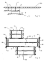
- Fig. 6 a plan view of the framework bottom surface of a system framework.
- the normal framework field has vertical stems 24 and horizontal bars 26 which connect the vertical stems 24 together (connections not shown in detail) and in which the framework floors 10 are suspended via their connection units 16.
- the scaffolding surface formed by the two scaffold floors 10.3 can now be extended in a simple manner with scaffold console surfaces.
- transverse connecting profile bars 30 are inserted through the corresponding recesses 20, 22 at the corresponding points in the transverse direction, which laterally project beyond the two scaffolding floors 10.3 in the inserted state.
- cross-connection profile bars 30 On the projecting region of the cross-connection profile bars 30 are from the outside two scaffolding floors 10 (in Fig. 6 left above) and two scaffolding floors 10.2 (in Fig. 6 Bottom right shown), that is, the cross-connection profile bars 30 are threaded into the corresponding recesses 20 and 22 of the scaffold floors 10 and 10.2.
- the cross-connection profile bars 30 furthermore have a protrusion on both sides, to which fixation units can be detachably connected, which prevent a gap from forming between the attached scaffolding floors 10 or 10.2.
- the cross-connection profile bars 30 have the further effect that the existing scaffold floors 10.3 of the system framework interact statically co-supporting, that is, in only one Load of a scaffold floor 10.3 the adjacent load transfer is used with, resulting in a reduction of the deflection result.
- cross-connection profile bars 30 for example steel round tubes can be used which have a diameter of 33.7 mm (millimeters), which diameter is common in the steel profile area.
- the recesses 20, 22 have a height H which is slightly larger than the diameter of the inserted transverse connection profile bars 30.
- the fixing units 40 may preferably be formed as pipe coupling units, which will be used in large numbers in scaffolding construction and then at the same time still offer the possibility to allow in addition to the fixation of adjacent scaffold floors and the connection of other scaffolding profile elements.
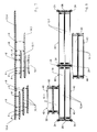
- Fig. 5 is schematically shown in a side view of the connection of scaffolding floors 10 to a scaffold floor 10.3 with different length offset, wherein adjacently arranged scaffolding floors 10.3, 10 in Fig. 5 are arranged one below the other.
- Fig. 8 shows by way of example a further embodiment of the training of console surfaces by laterally attaching scaffolding floors 10.2, 10.3 on in existing scaffold floors 10.4 inserted cross-connection profile bars 30. It is also possible to achieve scaffold floor expansions that extend at least partially over two scaffolding fields (in Fig. 8 shown below).
- Fig. 7 shows similar to Fig. 5 the arrangement of juxtaposed scaffolding floors with different length offset partly running over two scaffolding fields, whereby here also the adjoining scaffolding floors are arranged vertically offset in the representation.
- Fig. 9 is a section of a system framework such as the Layher flash scaffold system shown in the frame members with vertical stems 24 and Horizontal latch 26 are used. Overall, three scaffolding floors are shown. Each scaffold floor is formed by two suspended in the horizontal bar 26 scaffold floors 10.4. Through the recesses in the webs 14 of the scaffold floors 10.4, two cross-connection profile bars 30 are respectively inserted in the third and third points in each case by both adjacently arranged scaffolding floors 10.4 on the upper and middle scaffold floor, which project slightly beyond the front side. In this projecting area, in each case a vertical connection profile bar 32 is connected via coupling units not shown to the cross-connection profile bar 30 of the upper and lower equipment days.
- a vertical connection profile bar 32 is connected via coupling units not shown to the cross-connection profile bar 30 of the upper and lower equipment days.
- the vertical connection profile bars 32 are standard scaffolding tubes and, due to the geometry of the grid dimension of the recesses of the scaffolding floors 10.4, are arranged in the longitudinal direction in the framework system dimension S2. As a result, in a simple manner in the two console units 38, a system scaffold floor 10 can be hung easily.
- a major advantage of this design is that the console units 38 can be connected at virtually any height (arrow h) between the upper and middle scaffold floor levels.
- two scaffolding floors 10.4 are also suspended in the horizontal bar 26.
- cross-connection profile rods 30 inserted therethrough, which project forward and form a cantilever.
- two further scaffolding floors 10.4 are plugged on, so that a console surface results which corresponds to the scaffold floor area within the system scaffolding.
- FIG. 10 is a side view of a portion of a scaffolding system shown in which in each scaffold floor 10.4 in a vertical line each a cross-connection profile bar 30 is inserted through the corresponding recesses, wherein at its überkragendem end a vertical connection profile bar 32 is connected in each scaffolding floor level, except for the ground is guided. This will change the span of each Frame bottoms 10.4 approximately halved, resulting in increased payloads and lower deflections under load.
- Fig. 11 differs from the presentation according to Fig. 10 in that in this embodiment a total of three vertical connection profile bars 32 are connected to cross connection profile bars 30.
- Fig. 12 schematically shows the connection of a formed as a diagonal bar connection profile bar 34 is shown, which is also connected via inserted cross-connection profile bars 30, which are inserted inserted in a corresponding positioning on the scaffold floor 10.4.
- Fig. 13 shows the possibility, by means of inclined connecting profile rods 34, which are each connected to a cross-connection profile bar 30 and a vertical stem 24 to produce rigid frame corners.
- Fig. 14 shows a fragmentary perspective view of the formation of a scaffold floor surface between two lattice girders 50 in a first embodiment.
- the connection units 54 may be, for example, pipe coupling units, provided that the top flange is designed as a tubular profile.
- FIG Fig. 15 A further embodiment variant for forming a framework floor surface between two lattice girders 60 is shown in FIG Fig. 15 shown schematically in perspective.
- the scaffold bottoms 10.4 arranged between the two spaced lattice girders 60 at the level of the respective upper girths 62 run perpendicular to the upper gill 62 and are suspended in a simple manner via their connection units in the upper girth 62 designed as an upwardly open U-profile.
- Approximately in the third-third points are parallel to the lattice girder 60 through the recesses of the webs of the scaffolding floors 10.4 cross-connection profile bars 30 inserted, which connect the adjacent scaffolding floors 10.4 to a common plate.
- loads on one Scaffold floor 10.4 occur, not only removed from this one scaffold floor but distributed to adjacent scaffold floors 10.4.
- Fig. 16a and b show schematically in cross section a way to increase the load of a scaffold floor 10.4 in a simple manner.
- parallel to the longitudinal edge of the scaffold floor 10.4 support profile carrier available, according to Fig. 16a as I-profile 70 or as tube profile 72 according to Fig. 16b can be trained.
- the profiles 70, 72 are used to carry static under load in that at least one cross-connection profile bar 30 is inserted through the web recesses 20 of the framework floor 10.4, whose respective end region is connected to the I-profile 70 or the tube profile 72.
- connection units 74.1 and 74.2 are used, which are adapted to the corresponding geometry of the respective profile 70, 72.
- FIG. 17 schematically a section of a scaffolding system is shown, in which also vertical connection profile connecting rods 32 are connected to cross-connection profile bars 30, similar to the in 10 and 11 illustrated embodiments.
- the connecting profile bars 32 are not led to the bottom area but couple three superimposed scaffold floor, so that a load occurring on a scaffold floor distributed on three scaffolding floors.
- the vertical connection profile bars 32 are connected to the cross connection profile bars 30 both on the front side and on the rear side of the system frame.
- Fig. 18 schematically shows the formation of a pallet, which is formed in the embodiment by five juxtaposed scaffolding floors 10.4, wherein in the recesses of the webs a total of four cross-connection profile bars 30 are inserted in a relatively narrow grid. Means for releasably fixing the cross connection profile bars 30 in the inserted state are in Fig. 18 not shown in detail.
- Fig. 19 schematically shows the formation of a so-called scissor table, in which, for example, two adjacently arranged scaffolding floors 10.4 are present as a working floor surface. Through the recesses of the framework floors 10.4 are in the end and in the thirds of a total of four Cross connection profile bars 30 inserted so that the two adjacent scaffolding floors 10.4 act as a plate.
- a vertical rod 80 is connected via pipe coupling units, not shown, which is supported on the ground.
- two diagonal bars 82 are present, which together with the scaffold floor 10.4 and the vertical bar 80 form a bending-resistant corner.
- the diagonal bars 82 are connected on the upper side in each case to the cross-connection profile bars 30 inserted in the third-point points and are connected on the underside in the lower end area of the vertical bar 80.
- Fig. 20 schematically shows the simple connection of a railing construction 84 consisting of vertical stems 86 and horizontal bars 88 to a scaffold floor 10.4 with StegausEnglishungen by the vertical stems 36 are connected in the protruding end of inserted into the recesses of the scaffold floor 10 cross connection profile bars 30 in a simple manner.
- Inserted cross-connection profiles can also be used as a lifting protection for scaffold floors by connecting the profiles firmly to the floor via connected elements.
- Fig. 21 are two consecutively arranged steel scaffolding floors 10.5 shown, each having an enlarged Adapterrasterness AS and each have in their thirds three arranged in grid R recesses 20, 22.
- the grid dimension in the illustrated embodiment is 1197 mm (millimeters) and the grid dimension R 125 mm (millimeters).
- a scaffold floor 10.4 is shown, which is arranged laterally offset to the two scaffold floors 10.5 and is coupled via not shown cross-connection profile bars to the two scaffolding floors 10.5.
Landscapes
- Engineering & Computer Science (AREA)
- Architecture (AREA)
- Civil Engineering (AREA)
- Structural Engineering (AREA)
- Mechanical Engineering (AREA)
- Multimedia (AREA)
- Bridges Or Land Bridges (AREA)
- Floor Finish (AREA)
- Mutual Connection Of Rods And Tubes (AREA)
- Glass Compositions (AREA)
- Transition And Organic Metals Composition Catalysts For Addition Polymerization (AREA)
- Movable Scaffolding (AREA)
- Ladders (AREA)
- Graft Or Block Polymers (AREA)
- Polyurethanes Or Polyureas (AREA)
Applications Claiming Priority (2)
| Application Number | Priority Date | Filing Date | Title |
|---|---|---|---|
| DE10254033A DE10254033A1 (de) | 2002-11-20 | 2002-11-20 | Gerüstboden und Gerüst, Podium oder Tribüne mit einem derartigen Gerüstboden |
| EP03022475A EP1426523B1 (fr) | 2002-11-20 | 2003-10-08 | Plateforme d'échafaudage |
Related Parent Applications (2)
| Application Number | Title | Priority Date | Filing Date |
|---|---|---|---|
| EP03022475.2 Division | 2003-10-08 | ||
| EP03022475A Division EP1426523B1 (fr) | 2002-11-20 | 2003-10-08 | Plateforme d'échafaudage |
Publications (3)
| Publication Number | Publication Date |
|---|---|
| EP2045415A1 true EP2045415A1 (fr) | 2009-04-08 |
| EP2045415B1 EP2045415B1 (fr) | 2011-03-16 |
| EP2045415B9 EP2045415B9 (fr) | 2011-09-07 |
Family
ID=32240181
Family Applications (2)
| Application Number | Title | Priority Date | Filing Date |
|---|---|---|---|
| EP08019716A Expired - Lifetime EP2045415B9 (fr) | 2002-11-20 | 2003-10-08 | Echafaudage, podium ou tribune dotés d'un plancher d'échafaudage |
| EP03022475A Expired - Lifetime EP1426523B1 (fr) | 2002-11-20 | 2003-10-08 | Plateforme d'échafaudage |
Family Applications After (1)
| Application Number | Title | Priority Date | Filing Date |
|---|---|---|---|
| EP03022475A Expired - Lifetime EP1426523B1 (fr) | 2002-11-20 | 2003-10-08 | Plateforme d'échafaudage |
Country Status (4)
| Country | Link |
|---|---|
| EP (2) | EP2045415B9 (fr) |
| AT (2) | ATE502171T1 (fr) |
| DE (3) | DE10254033A1 (fr) |
| ES (2) | ES2362152T3 (fr) |
Families Citing this family (10)
| Publication number | Priority date | Publication date | Assignee | Title |
|---|---|---|---|---|
| NO319365B1 (no) * | 2003-11-12 | 2005-07-18 | Rh Products Int As | Gulvelement for stillas |
| DE202004017539U1 (de) * | 2004-11-11 | 2005-02-03 | Zinco Gmbh | System als Anschlagmöglichkeit für Schutzausrüstungen gegen Absturz |
| DE102008015066A1 (de) | 2008-03-19 | 2009-09-24 | Wilhelm Layher Verwaltungs-Gmbh | Belageinheit mit Abhebesicherung und Verfahren zur Sicherung einer Belageinheit gegen Abheben sowie Verfahren zur Entsicherung einer gegen Abheben gesicherten Belageinheit |
| DE202012101000U1 (de) | 2012-03-21 | 2013-03-25 | Wilhelm Layher Verwaltungs-Gmbh | Überlappungs-Anordnung von wenigstens zwei Laufplanken |
| EP2792813A1 (fr) * | 2013-04-16 | 2014-10-22 | Mon.zon Development AB | Élément de stabilisation |
| GB2524780B (en) * | 2014-04-02 | 2017-09-13 | David Westlake Peter | Modular scaffold board |
| DE102015108650A1 (de) * | 2015-06-01 | 2016-12-01 | Wilhelm Layher Verwaltungs-Gmbh | Gerüstbodenelement, insbesondere für ein Baugerüst |
| DE102018218849A1 (de) * | 2018-11-06 | 2020-05-07 | Peri Gmbh | Gerüstsystem und Verfahren zur Herstellung des Gerüstsystems |
| DE102022200448A1 (de) | 2022-01-17 | 2023-07-20 | Peri Se | Unterzug für Gerüstbeläge, Gerüstbelagebene, Verfahren zur Ausbildung einer Gerüstbelagebene sowie Verwendung eines Unterzugs |
| DE102023135895A1 (de) * | 2023-12-19 | 2025-06-26 | Wilhelm Layher Verwaltungs-Gmbh | Verfahren zur vorlaufenden montage eines erweiterungs-gerüstträgers und wenigstens eines sich daran abstützenden erweiterungs-gerüstbodens |
Citations (3)
| Publication number | Priority date | Publication date | Assignee | Title |
|---|---|---|---|---|
| DE1559034A1 (de) | 1965-11-09 | 1969-08-21 | Hans Meisch | Abschlagbares Arbeitsgeruest |
| US4984654A (en) | 1990-05-10 | 1991-01-15 | Carl Anderson | Scaffold safety system |
| DE19515062A1 (de) | 1995-04-27 | 1996-10-31 | Langer Ruth Geb Layher | Gerüstboden |
Family Cites Families (4)
| Publication number | Priority date | Publication date | Assignee | Title |
|---|---|---|---|---|
| US2676066A (en) * | 1951-05-25 | 1954-04-20 | Woboril Company | Folding swing stage |
| US3804198A (en) * | 1972-09-07 | 1974-04-16 | J Palumbo | Combination ladder and mudboard |
| JPS6030760A (ja) * | 1983-07-31 | 1985-02-16 | 日綜産業株式会社 | 工事用可搬式歩廊 |
| DE19923765C2 (de) * | 1999-05-22 | 2001-05-31 | Horst Laug | Leiter mit Diele |
-
2002
- 2002-11-20 DE DE10254033A patent/DE10254033A1/de not_active Withdrawn
-
2003
- 2003-10-08 ES ES08019716T patent/ES2362152T3/es not_active Expired - Lifetime
- 2003-10-08 EP EP08019716A patent/EP2045415B9/fr not_active Expired - Lifetime
- 2003-10-08 ES ES03022475T patent/ES2329454T3/es not_active Expired - Lifetime
- 2003-10-08 AT AT08019716T patent/ATE502171T1/de active
- 2003-10-08 EP EP03022475A patent/EP1426523B1/fr not_active Expired - Lifetime
- 2003-10-08 AT AT03022475T patent/ATE438773T1/de active
- 2003-10-08 DE DE50311773T patent/DE50311773D1/de not_active Expired - Lifetime
- 2003-10-08 DE DE50313556T patent/DE50313556D1/de not_active Expired - Lifetime
Patent Citations (3)
| Publication number | Priority date | Publication date | Assignee | Title |
|---|---|---|---|---|
| DE1559034A1 (de) | 1965-11-09 | 1969-08-21 | Hans Meisch | Abschlagbares Arbeitsgeruest |
| US4984654A (en) | 1990-05-10 | 1991-01-15 | Carl Anderson | Scaffold safety system |
| DE19515062A1 (de) | 1995-04-27 | 1996-10-31 | Langer Ruth Geb Layher | Gerüstboden |
Also Published As
| Publication number | Publication date |
|---|---|
| DE50311773D1 (de) | 2009-09-17 |
| ES2329454T3 (es) | 2009-11-26 |
| DE10254033A1 (de) | 2004-06-03 |
| EP2045415B9 (fr) | 2011-09-07 |
| DE50313556D1 (de) | 2011-04-28 |
| EP1426523A1 (fr) | 2004-06-09 |
| ATE502171T1 (de) | 2011-04-15 |
| ATE438773T1 (de) | 2009-08-15 |
| EP2045415B1 (fr) | 2011-03-16 |
| ES2362152T3 (es) | 2011-06-29 |
| EP1426523B1 (fr) | 2009-08-05 |
Similar Documents
| Publication | Publication Date | Title |
|---|---|---|
| EP2045415B1 (fr) | Echafaudage, podium ou tribune dotés d'un plancher d'échafaudage | |
| WO2004079127A1 (fr) | Dispositif pour fixer des plaques contre les murs exterieurs d'edifices | |
| EP1544377B1 (fr) | Element de coffrage pour murs courbes | |
| AT390987B (de) | Tragkonstruktion fuer tribuenen | |
| EP1370736B1 (fr) | Systeme de composants pour podiums/plates-formes et/ou tribunes et/ou estrades | |
| DE202012009433U1 (de) | Regalsysem | |
| EP0411113B1 (fr) | Escalier | |
| EP3650616B1 (fr) | Toit de protection contre les intempéries de textile tendu pourvu de bordure d'appui sur le textile | |
| DE820963C (de) | Baugeruest mit aus Rohren bestehenden Staendern | |
| DE9410743U1 (de) | Rahmenelement | |
| EP2977526A1 (fr) | Équerre de fixation pour coffrages de rives de dalle | |
| DE29912555U1 (de) | Konsoleinrichtung für eine Gerüstvorrichtung | |
| AT500952A4 (de) | Gerüstträger aus aluminium | |
| EP2275625B1 (fr) | Construction d'échafaudage pour un échafaudage principal et un second échafaudage, notamment un escalier d'échafaudage | |
| EP0851074B1 (fr) | Echafaudage pour plate-forme, charpente ou coffrage de dalle | |
| DE3447300A1 (de) | Regal mit auf pfosten und diese miteinander verbindenden horizontalstreben | |
| DE2236165A1 (de) | Geruest | |
| EP4194641A1 (fr) | Module d'échafaudage pour un échafaudage de support ou de support ainsi qu'échafaudage de support ou de support | |
| DE202004007550U1 (de) | Stellrahmen | |
| DE3051155C2 (en) | Mobile scaffolding and ladder components | |
| DE19622400A1 (de) | Verbindungsbeschlag für Gerüste | |
| DE69108816T2 (de) | Verbesserte modulare Stützvorrichtung. | |
| EP1092821A1 (fr) | Support, en particuler pour des dispositifs de coffrage pour construction en béton | |
| DE1409400C (de) | Zerlegbare Tribune | |
| DE227576C (fr) |
Legal Events
| Date | Code | Title | Description |
|---|---|---|---|
| PUAI | Public reference made under article 153(3) epc to a published international application that has entered the european phase |
Free format text: ORIGINAL CODE: 0009012 |
|
| AC | Divisional application: reference to earlier application |
Ref document number: 1426523 Country of ref document: EP Kind code of ref document: P |
|
| AK | Designated contracting states |
Kind code of ref document: A1 Designated state(s): AT BE BG CH CY CZ DE DK EE ES FI FR GB GR HU IE IT LI LU MC NL PT RO SE SI SK TR |
|
| 17P | Request for examination filed |
Effective date: 20090930 |
|
| 17Q | First examination report despatched |
Effective date: 20091026 |
|
| AKX | Designation fees paid |
Designated state(s): AT BE BG CH CY CZ DE DK EE ES FI FR GB GR HU IE IT LI LU MC NL PT RO SE SI SK TR |
|
| GRAP | Despatch of communication of intention to grant a patent |
Free format text: ORIGINAL CODE: EPIDOSNIGR1 |
|
| GRAS | Grant fee paid |
Free format text: ORIGINAL CODE: EPIDOSNIGR3 |
|
| GRAA | (expected) grant |
Free format text: ORIGINAL CODE: 0009210 |
|
| AC | Divisional application: reference to earlier application |
Ref document number: 1426523 Country of ref document: EP Kind code of ref document: P |
|
| AK | Designated contracting states |
Kind code of ref document: B1 Designated state(s): AT BE BG CH CY CZ DE DK EE ES FI FR GB GR HU IE IT LI LU MC NL PT RO SE SI SK TR |
|
| REG | Reference to a national code |
Ref country code: GB Ref legal event code: FG4D Free format text: NOT ENGLISH |
|
| REG | Reference to a national code |
Ref country code: CH Ref legal event code: EP |
|
| REG | Reference to a national code |
Ref country code: IE Ref legal event code: FG4D |
|
| REF | Corresponds to: |
Ref document number: 50313556 Country of ref document: DE Date of ref document: 20110428 Kind code of ref document: P |
|
| REG | Reference to a national code |
Ref country code: DE Ref legal event code: R096 Ref document number: 50313556 Country of ref document: DE Effective date: 20110428 |
|
| REG | Reference to a national code |
Ref country code: CH Ref legal event code: NV Representative=s name: ISLER & PEDRAZZINI AG |
|
| REG | Reference to a national code |
Ref country code: NL Ref legal event code: T3 Ref country code: ES Ref legal event code: FG2A Ref document number: 2362152 Country of ref document: ES Kind code of ref document: T3 Effective date: 20110629 |
|
| REG | Reference to a national code |
Ref country code: SE Ref legal event code: TRGR |
|
| PG25 | Lapsed in a contracting state [announced via postgrant information from national office to epo] |
Ref country code: SI Free format text: LAPSE BECAUSE OF FAILURE TO SUBMIT A TRANSLATION OF THE DESCRIPTION OR TO PAY THE FEE WITHIN THE PRESCRIBED TIME-LIMIT Effective date: 20110316 Ref country code: FI Free format text: LAPSE BECAUSE OF FAILURE TO SUBMIT A TRANSLATION OF THE DESCRIPTION OR TO PAY THE FEE WITHIN THE PRESCRIBED TIME-LIMIT Effective date: 20110316 Ref country code: BG Free format text: LAPSE BECAUSE OF FAILURE TO SUBMIT A TRANSLATION OF THE DESCRIPTION OR TO PAY THE FEE WITHIN THE PRESCRIBED TIME-LIMIT Effective date: 20110616 Ref country code: CY Free format text: LAPSE BECAUSE OF FAILURE TO SUBMIT A TRANSLATION OF THE DESCRIPTION OR TO PAY THE FEE WITHIN THE PRESCRIBED TIME-LIMIT Effective date: 20110316 |
|
| REG | Reference to a national code |
Ref country code: IE Ref legal event code: FD4D |
|
| PG25 | Lapsed in a contracting state [announced via postgrant information from national office to epo] |
Ref country code: IE Free format text: LAPSE BECAUSE OF FAILURE TO SUBMIT A TRANSLATION OF THE DESCRIPTION OR TO PAY THE FEE WITHIN THE PRESCRIBED TIME-LIMIT Effective date: 20110316 Ref country code: PT Free format text: LAPSE BECAUSE OF FAILURE TO SUBMIT A TRANSLATION OF THE DESCRIPTION OR TO PAY THE FEE WITHIN THE PRESCRIBED TIME-LIMIT Effective date: 20110718 Ref country code: EE Free format text: LAPSE BECAUSE OF FAILURE TO SUBMIT A TRANSLATION OF THE DESCRIPTION OR TO PAY THE FEE WITHIN THE PRESCRIBED TIME-LIMIT Effective date: 20110316 |
|
| PG25 | Lapsed in a contracting state [announced via postgrant information from national office to epo] |
Ref country code: RO Free format text: LAPSE BECAUSE OF FAILURE TO SUBMIT A TRANSLATION OF THE DESCRIPTION OR TO PAY THE FEE WITHIN THE PRESCRIBED TIME-LIMIT Effective date: 20110316 Ref country code: SK Free format text: LAPSE BECAUSE OF FAILURE TO SUBMIT A TRANSLATION OF THE DESCRIPTION OR TO PAY THE FEE WITHIN THE PRESCRIBED TIME-LIMIT Effective date: 20110316 Ref country code: CZ Free format text: LAPSE BECAUSE OF FAILURE TO SUBMIT A TRANSLATION OF THE DESCRIPTION OR TO PAY THE FEE WITHIN THE PRESCRIBED TIME-LIMIT Effective date: 20110316 |
|
| PLBE | No opposition filed within time limit |
Free format text: ORIGINAL CODE: 0009261 |
|
| STAA | Information on the status of an ep patent application or granted ep patent |
Free format text: STATUS: NO OPPOSITION FILED WITHIN TIME LIMIT |
|
| 26N | No opposition filed |
Effective date: 20111219 |
|
| PG25 | Lapsed in a contracting state [announced via postgrant information from national office to epo] |
Ref country code: DK Free format text: LAPSE BECAUSE OF FAILURE TO SUBMIT A TRANSLATION OF THE DESCRIPTION OR TO PAY THE FEE WITHIN THE PRESCRIBED TIME-LIMIT Effective date: 20110316 |
|
| REG | Reference to a national code |
Ref country code: DE Ref legal event code: R097 Ref document number: 50313556 Country of ref document: DE Effective date: 20111219 |
|
| BERE | Be: lapsed |
Owner name: WILHELM LAYHER VERWALTUNGS-GMBH Effective date: 20111031 |
|
| PG25 | Lapsed in a contracting state [announced via postgrant information from national office to epo] |
Ref country code: MC Free format text: LAPSE BECAUSE OF NON-PAYMENT OF DUE FEES Effective date: 20111031 |
|
| PG25 | Lapsed in a contracting state [announced via postgrant information from national office to epo] |
Ref country code: BE Free format text: LAPSE BECAUSE OF NON-PAYMENT OF DUE FEES Effective date: 20111031 |
|
| REG | Reference to a national code |
Ref country code: AT Ref legal event code: MM01 Ref document number: 502171 Country of ref document: AT Kind code of ref document: T Effective date: 20111008 |
|
| PG25 | Lapsed in a contracting state [announced via postgrant information from national office to epo] |
Ref country code: AT Free format text: LAPSE BECAUSE OF NON-PAYMENT OF DUE FEES Effective date: 20111008 |
|
| PG25 | Lapsed in a contracting state [announced via postgrant information from national office to epo] |
Ref country code: LU Free format text: LAPSE BECAUSE OF NON-PAYMENT OF DUE FEES Effective date: 20111008 |
|
| PG25 | Lapsed in a contracting state [announced via postgrant information from national office to epo] |
Ref country code: TR Free format text: LAPSE BECAUSE OF FAILURE TO SUBMIT A TRANSLATION OF THE DESCRIPTION OR TO PAY THE FEE WITHIN THE PRESCRIBED TIME-LIMIT Effective date: 20110316 |
|
| PG25 | Lapsed in a contracting state [announced via postgrant information from national office to epo] |
Ref country code: HU Free format text: LAPSE BECAUSE OF FAILURE TO SUBMIT A TRANSLATION OF THE DESCRIPTION OR TO PAY THE FEE WITHIN THE PRESCRIBED TIME-LIMIT Effective date: 20110316 |
|
| PG25 | Lapsed in a contracting state [announced via postgrant information from national office to epo] |
Ref country code: GR Free format text: LAPSE BECAUSE OF FAILURE TO SUBMIT A TRANSLATION OF THE DESCRIPTION OR TO PAY THE FEE WITHIN THE PRESCRIBED TIME-LIMIT Effective date: 20110316 |
|
| REG | Reference to a national code |
Ref country code: FR Ref legal event code: PLFP Year of fee payment: 13 |
|
| REG | Reference to a national code |
Ref country code: FR Ref legal event code: PLFP Year of fee payment: 14 |
|
| REG | Reference to a national code |
Ref country code: FR Ref legal event code: PLFP Year of fee payment: 15 |
|
| REG | Reference to a national code |
Ref country code: FR Ref legal event code: PLFP Year of fee payment: 16 |
|
| PGFP | Annual fee paid to national office [announced via postgrant information from national office to epo] |
Ref country code: NL Payment date: 20221021 Year of fee payment: 20 Ref country code: FR Payment date: 20221020 Year of fee payment: 20 |
|
| PGFP | Annual fee paid to national office [announced via postgrant information from national office to epo] |
Ref country code: SE Payment date: 20221020 Year of fee payment: 20 Ref country code: IT Payment date: 20221031 Year of fee payment: 20 Ref country code: GB Payment date: 20221024 Year of fee payment: 20 Ref country code: ES Payment date: 20221118 Year of fee payment: 20 Ref country code: DE Payment date: 20221021 Year of fee payment: 20 |
|
| PGFP | Annual fee paid to national office [announced via postgrant information from national office to epo] |
Ref country code: CH Payment date: 20221027 Year of fee payment: 20 |
|
| P01 | Opt-out of the competence of the unified patent court (upc) registered |
Effective date: 20230516 |
|
| REG | Reference to a national code |
Ref country code: DE Ref legal event code: R071 Ref document number: 50313556 Country of ref document: DE |
|
| REG | Reference to a national code |
Ref country code: NL Ref legal event code: MK Effective date: 20231007 |
|
| REG | Reference to a national code |
Ref country code: CH Ref legal event code: PL |
|
| REG | Reference to a national code |
Ref country code: ES Ref legal event code: FD2A Effective date: 20231027 |
|
| REG | Reference to a national code |
Ref country code: GB Ref legal event code: PE20 Expiry date: 20231007 |
|
| REG | Reference to a national code |
Ref country code: SE Ref legal event code: EUG |
|
| PG25 | Lapsed in a contracting state [announced via postgrant information from national office to epo] |
Ref country code: GB Free format text: LAPSE BECAUSE OF EXPIRATION OF PROTECTION Effective date: 20231007 |
|
| PG25 | Lapsed in a contracting state [announced via postgrant information from national office to epo] |
Ref country code: ES Free format text: LAPSE BECAUSE OF EXPIRATION OF PROTECTION Effective date: 20231009 |
|
| PG25 | Lapsed in a contracting state [announced via postgrant information from national office to epo] |
Ref country code: GB Free format text: LAPSE BECAUSE OF EXPIRATION OF PROTECTION Effective date: 20231007 Ref country code: ES Free format text: LAPSE BECAUSE OF EXPIRATION OF PROTECTION Effective date: 20231009 |