EP2045514A1 - Modular reflective optical lighting system and lighting device equipped therewith, in particular for vehicles - Google Patents
Modular reflective optical lighting system and lighting device equipped therewith, in particular for vehicles Download PDFInfo
- Publication number
- EP2045514A1 EP2045514A1 EP20070425625 EP07425625A EP2045514A1 EP 2045514 A1 EP2045514 A1 EP 2045514A1 EP 20070425625 EP20070425625 EP 20070425625 EP 07425625 A EP07425625 A EP 07425625A EP 2045514 A1 EP2045514 A1 EP 2045514A1
- Authority
- EP
- European Patent Office
- Prior art keywords
- optical system
- light source
- optical axis
- printed circuit
- light
- Prior art date
- Legal status (The legal status is an assumption and is not a legal conclusion. Google has not performed a legal analysis and makes no representation as to the accuracy of the status listed.)
- Granted
Links
Images


Classifications
-
- F—MECHANICAL ENGINEERING; LIGHTING; HEATING; WEAPONS; BLASTING
- F21—LIGHTING
- F21V—FUNCTIONAL FEATURES OR DETAILS OF LIGHTING DEVICES OR SYSTEMS THEREOF; STRUCTURAL COMBINATIONS OF LIGHTING DEVICES WITH OTHER ARTICLES, NOT OTHERWISE PROVIDED FOR
- F21V7/00—Reflectors for light sources
- F21V7/0025—Combination of two or more reflectors for a single light source
-
- F—MECHANICAL ENGINEERING; LIGHTING; HEATING; WEAPONS; BLASTING
- F21—LIGHTING
- F21S—NON-PORTABLE LIGHTING DEVICES; SYSTEMS THEREOF; VEHICLE LIGHTING DEVICES SPECIALLY ADAPTED FOR VEHICLE EXTERIORS
- F21S41/00—Illuminating devices specially adapted for vehicle exteriors, e.g. headlamps
- F21S41/10—Illuminating devices specially adapted for vehicle exteriors, e.g. headlamps characterised by the light source
- F21S41/14—Illuminating devices specially adapted for vehicle exteriors, e.g. headlamps characterised by the light source characterised by the type of light source
- F21S41/141—Light emitting diodes [LED]
- F21S41/147—Light emitting diodes [LED] the main emission direction of the LED being angled to the optical axis of the illuminating device
- F21S41/148—Light emitting diodes [LED] the main emission direction of the LED being angled to the optical axis of the illuminating device the main emission direction of the LED being perpendicular to the optical axis
-
- F—MECHANICAL ENGINEERING; LIGHTING; HEATING; WEAPONS; BLASTING
- F21—LIGHTING
- F21S—NON-PORTABLE LIGHTING DEVICES; SYSTEMS THEREOF; VEHICLE LIGHTING DEVICES SPECIALLY ADAPTED FOR VEHICLE EXTERIORS
- F21S41/00—Illuminating devices specially adapted for vehicle exteriors, e.g. headlamps
- F21S41/20—Illuminating devices specially adapted for vehicle exteriors, e.g. headlamps characterised by refractors, transparent cover plates, light guides or filters
- F21S41/24—Light guides
-
- F—MECHANICAL ENGINEERING; LIGHTING; HEATING; WEAPONS; BLASTING
- F21—LIGHTING
- F21S—NON-PORTABLE LIGHTING DEVICES; SYSTEMS THEREOF; VEHICLE LIGHTING DEVICES SPECIALLY ADAPTED FOR VEHICLE EXTERIORS
- F21S41/00—Illuminating devices specially adapted for vehicle exteriors, e.g. headlamps
- F21S41/30—Illuminating devices specially adapted for vehicle exteriors, e.g. headlamps characterised by reflectors
- F21S41/32—Optical layout thereof
- F21S41/33—Multi-surface reflectors, e.g. reflectors with facets or reflectors with portions of different curvature
- F21S41/334—Multi-surface reflectors, e.g. reflectors with facets or reflectors with portions of different curvature the reflector consisting of patch like sectors
- F21S41/336—Multi-surface reflectors, e.g. reflectors with facets or reflectors with portions of different curvature the reflector consisting of patch like sectors with discontinuity at the junction between adjacent areas
-
- F—MECHANICAL ENGINEERING; LIGHTING; HEATING; WEAPONS; BLASTING
- F21—LIGHTING
- F21S—NON-PORTABLE LIGHTING DEVICES; SYSTEMS THEREOF; VEHICLE LIGHTING DEVICES SPECIALLY ADAPTED FOR VEHICLE EXTERIORS
- F21S43/00—Signalling devices specially adapted for vehicle exteriors, e.g. brake lamps, direction indicator lights or reversing lights
- F21S43/10—Signalling devices specially adapted for vehicle exteriors, e.g. brake lamps, direction indicator lights or reversing lights characterised by the light source
- F21S43/13—Signalling devices specially adapted for vehicle exteriors, e.g. brake lamps, direction indicator lights or reversing lights characterised by the light source characterised by the type of light source
- F21S43/14—Light emitting diodes [LED]
-
- F—MECHANICAL ENGINEERING; LIGHTING; HEATING; WEAPONS; BLASTING
- F21—LIGHTING
- F21S—NON-PORTABLE LIGHTING DEVICES; SYSTEMS THEREOF; VEHICLE LIGHTING DEVICES SPECIALLY ADAPTED FOR VEHICLE EXTERIORS
- F21S43/00—Signalling devices specially adapted for vehicle exteriors, e.g. brake lamps, direction indicator lights or reversing lights
- F21S43/20—Signalling devices specially adapted for vehicle exteriors, e.g. brake lamps, direction indicator lights or reversing lights characterised by refractors, transparent cover plates, light guides or filters
- F21S43/235—Light guides
- F21S43/251—Light guides the light guides being used to transmit light from remote light sources
-
- F—MECHANICAL ENGINEERING; LIGHTING; HEATING; WEAPONS; BLASTING
- F21—LIGHTING
- F21S—NON-PORTABLE LIGHTING DEVICES; SYSTEMS THEREOF; VEHICLE LIGHTING DEVICES SPECIALLY ADAPTED FOR VEHICLE EXTERIORS
- F21S43/00—Signalling devices specially adapted for vehicle exteriors, e.g. brake lamps, direction indicator lights or reversing lights
- F21S43/30—Signalling devices specially adapted for vehicle exteriors, e.g. brake lamps, direction indicator lights or reversing lights characterised by reflectors
-
- F—MECHANICAL ENGINEERING; LIGHTING; HEATING; WEAPONS; BLASTING
- F21—LIGHTING
- F21S—NON-PORTABLE LIGHTING DEVICES; SYSTEMS THEREOF; VEHICLE LIGHTING DEVICES SPECIALLY ADAPTED FOR VEHICLE EXTERIORS
- F21S43/00—Signalling devices specially adapted for vehicle exteriors, e.g. brake lamps, direction indicator lights or reversing lights
- F21S43/30—Signalling devices specially adapted for vehicle exteriors, e.g. brake lamps, direction indicator lights or reversing lights characterised by reflectors
- F21S43/31—Optical layout thereof
-
- F—MECHANICAL ENGINEERING; LIGHTING; HEATING; WEAPONS; BLASTING
- F21—LIGHTING
- F21S—NON-PORTABLE LIGHTING DEVICES; SYSTEMS THEREOF; VEHICLE LIGHTING DEVICES SPECIALLY ADAPTED FOR VEHICLE EXTERIORS
- F21S41/00—Illuminating devices specially adapted for vehicle exteriors, e.g. headlamps
- F21S41/10—Illuminating devices specially adapted for vehicle exteriors, e.g. headlamps characterised by the light source
- F21S41/14—Illuminating devices specially adapted for vehicle exteriors, e.g. headlamps characterised by the light source characterised by the type of light source
- F21S41/141—Light emitting diodes [LED]
- F21S41/151—Light emitting diodes [LED] arranged in one or more lines
- F21S41/153—Light emitting diodes [LED] arranged in one or more lines arranged in a matrix
-
- F—MECHANICAL ENGINEERING; LIGHTING; HEATING; WEAPONS; BLASTING
- F21—LIGHTING
- F21S—NON-PORTABLE LIGHTING DEVICES; SYSTEMS THEREOF; VEHICLE LIGHTING DEVICES SPECIALLY ADAPTED FOR VEHICLE EXTERIORS
- F21S43/00—Signalling devices specially adapted for vehicle exteriors, e.g. brake lamps, direction indicator lights or reversing lights
- F21S43/20—Signalling devices specially adapted for vehicle exteriors, e.g. brake lamps, direction indicator lights or reversing lights characterised by refractors, transparent cover plates, light guides or filters
- F21S43/235—Light guides
-
- F—MECHANICAL ENGINEERING; LIGHTING; HEATING; WEAPONS; BLASTING
- F21—LIGHTING
- F21Y—INDEXING SCHEME ASSOCIATED WITH SUBCLASSES F21K, F21L, F21S and F21V, RELATING TO THE FORM OR THE KIND OF THE LIGHT SOURCES OR OF THE COLOUR OF THE LIGHT EMITTED
- F21Y2115/00—Light-generating elements of semiconductor light sources
- F21Y2115/10—Light-emitting diodes [LED]
Definitions
- the present invention relates to a modular reflective optical lighting system, and a lighting device equipped therewith, in particular a vehicle light or headlight, wherein the desired brightness distribution is achieved, among other things, by juxtaposing inside a single body two or more modular optical systems comprising the same "basic" components, the latter being more or less identical to one another.
- DRL Daytime Running Light function
- progressive illumination of bends cornering
- WO2007069123 for example relates to a vehicle dipped-beam headlight that is provided with a solid-state light source (LED).
- LED solid-state light source
- the term "light source” refers to any light source (LED, incandescent lamp, discharge lamp, etc.) in which the light rays that are emitted can be approximated as ideally radiating from a single point, for example, in case of incandescent lamps, from the middle of the filament.
- This definition therefore excludes light sources such as neon tubes, in which the light rays are radiated from a plurality of adjacent points arranged along an axis.
- the headlight described in WO2007069123 while using a LED as the light source, is relatively large and complex, due to the need to overcome a series of practical design problems associated with the use of a single solid-state light source that is sufficiently powerful to achieve the brightness distribution required by a headlight.
- DE19820267 describes a reflective optical lighting system that uses a LED light source and achieves uniform distribution of the emitted light in a system with limited overall dimensions; said optical system is based on the connection of the light source with a reflector consisting of a convex element the convexity of which lies in the main direction of emission of the light source; the convex element can consist of a curved surface or of two reflecting surfaces of any shape (flat, concave or convex) joined together at an angle.
- This type of optical system conceived for the rear illumination of a display, for example a liquid crystal display, can in theory also be used for vehicle lighting devices, but in that case its use would clearly be limited to lamps only.
- the purpose of the present invention is therefore to provide a reflective optical lighting system with reduced overall dimensions that is suitable to use light sources consisting of LEDs, as in the case of the optical system described in DE19820267 , but which is more versatile and in particular can be used indifferently to produce lamps and headlights and can therefore be used in the manufacture of indicator and lighting devices for vehicles that are cheap to produce, light in weight, have reduced overall dimensions and low electricity consumption, possibly with a single device incorporating a multitude of different optical functions, thus overcoming the limits of the prior art.
- a reflective optical system is provided as set forth in claim 1.
- the reflective optical lighting system comprises at least one light source having a first optical axis defining a main direction of radiation of light rays emitted by said source and at least a first and a second reflecting surface operationally associated with the light source to intercept the light rays and arranged so as to form between them a first pre-defined angle of a size other than 180°; unlike in DE19820267 , however, the first and second reflecting surfaces delimit, between them, a concavity oriented towards the light source and are shaped so that, when in use, said concavity receives a substantial portion of said light rays emitted by the source to reflect them in a direction forming with the first optical axis a second angle of a pre-defined size, so that the reflected rays present a main direction of radiation defined by a second optical axis essentially perpendicular to the first.
- the light source that is used is preferably a Lambertian light source and in that case the concavity defined between the first and the second reflecting surfaces and oriented towards the light source occupies a solid angle greater than n steradians, i.e. greater than a quarter of the solid spherical angle, and in any case such that at least 30% of the light rays emitted by the source are intercepted by the first and second reflecting surfaces.
- the optical system according to the invention can also comprise at least one bright, clear or coloured secondary optical element, operationally associated with the first and second reflecting surfaces in the direction defined by the second optical axis and consisting of at least a lens or a matrix of micro-optics arranged transversely to the second optical axis.
- the optical system according to the invention can comprise a plurality of light sources, each operationally associated with a first and second reflecting surface to form therewith a single lighting module so that said system consists of a plurality of lighting modules mutually juxtaposed in a one-dimensional or two-dimensional matrix arrangement.
- the invention also relates to a lighting device comprising a cup-shaped element, preferably made of plastic or metal and fixable to the body of a vehicle, and at least a transparent fluid-tight sealing element to close an opening in the cup-shaped element in which said optical system is arranged and housed in a position oriented towards the opening and such that the second optical axis intercepts the transparent closing element and when used is directly parallel to a direction in which the vehicle is travelling.
- both headlights in particular those intrinsically incorporating a bright-dark or cut-off line such as main-beam headlights or fog lights, in which the light source, in particular a LED light source, is assembled face-down - hereinafter referred to as DLA, for "Down LED Assembly” - so that the parasite rays illuminate the road and are not dispersed upwards), and indicator lights (position or direction indicators, etc.)
- DLA Down LED Assembly
- lighting devices that consist of a single “basic” optical module, comprising a light source and the two reflecting surfaces associated therewith joined at an angle of approximately 90° depending on the desired brightness distribution (symmetric or asymmetric).
- a “basic” module can be connected vertically or horizontally to one or more identical or similar modules, in order to obtain a complex system, which allows the use of particular types of activation logic, for example to activate the different modules gradually as a function of the steering angle of the vehicle (the "Static Bend Lighting” function).
- the light sources can be incandescent lamps or solid-state sources (LEDs).
- the LEDs can be SMDs (Surface Mounted Devices) or dies (semiconductors only), possibly in a matrix arrangement. If several chips are used in the same basic module for example, different coloured lights can be obtained, using the same pair of angled reflecting surfaces for different functions, by appropriately mixing the contributions deriving from different monochromatic LED sources. For example, using RGB (Red Green Blue) LEDs, the same function can be used for the direction indicator, DRL and particular sectors of the dipped-beam / main-beam functions.
- RGB Red Green Blue
- Possible fields of application for the present invention are therefore headlights or lamps for cars, both to implement indicator functions (direction indicators, DRL, position indicators, side markers) and lighting functions (dipped-beam, main-beam, fog lights, SBL).
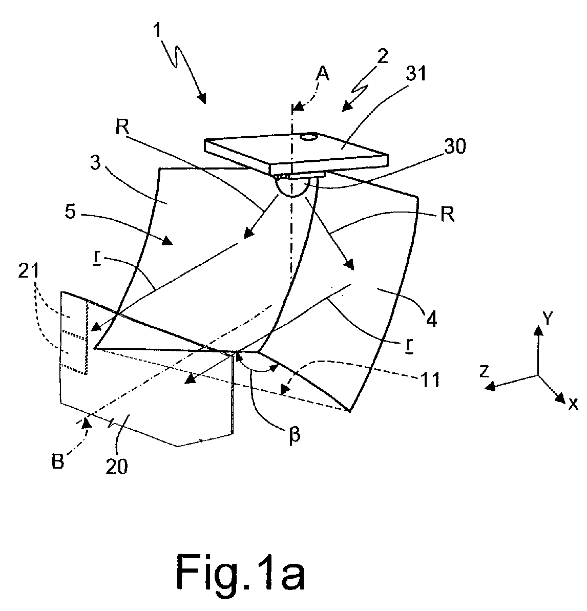
- reference number 1 indicates a reflective optical lighting system comprising at least one light source 2 and at least a first reflecting surface 3 and a second reflecting surface 4 operationally associated with the light source 2 and arranged obliquely in relation to one another; in particular, the light source 2 has a first optical axis A defining a main direction of radiation of light rays R emitted by said source 2 and the reflecting surfaces 3 and 4, which may be flat, concave or convex and can be defined by a single equation or by a complex series of equations, are oriented with respect to the axis A to intercept the light rays R and are in particular arranged to form between them a preset first angle ⁇ of a size other than 180°.
- the reflecting surfaces 3 and 4 between them delimit a concavity 5 oriented towards the light source 2 and are shaped so that when in use said concavity 5 receives a substantial portion of the light rays R emitted by the source 2 to reflect them in a direction forming with the optical axis A an angle ⁇ ( figure 5 ) of a preset size, so that the reflected rays r present a main direction of radiation defined by a second optical axis B, essentially perpendicular to the optical axis A.
- the angle ⁇ between the two reflecting surfaces 3,4 arranged obliquely in relation to one another is 90° or in the region of 90°, for example ( figures 3a and 3b ) said angle is respectively less than 90° ( figure 3b ) or more than 90° ( figure 3a ), thus achieving a respectively asymmetric and symmetric brightness distribution of the reflected rays r with respect to the optical axis B.
- the size of the angle ⁇ can be between 50° and 150° and, more preferably, it is between the values ⁇ 1 of 85° and ⁇ 2 of 100°.
- the reflective optical system 1 described herein preferably comprises, for each first and second reflecting surface 3 and 4, associated with a single light source 2, at least a third reflecting surface 10 ( figure 5 ) and/or 11 ( figure 1a ) oriented towards the concavity 5 and in any case arranged essentially perpendicularly to the optical axis A, in order to also produce in the direction defined by the optical axis B reflected rays r' ( figure 5 ) which have undergone a double reflection, for example so as to send almost all of the light rays R emitted by the source 2 below a bright-dark cut-off mark L ( figure 3 ).
- the light source 2 is preferably, but not necessarily, a Lambertian light source and the concavity 5 defined between the reflecting surfaces 3 and 4 and oriented towards the light source 2 occupies a solid angle greater than n steradians, i.e. greater than a quarter of the solid spherical angle, and in any case such that at least 30% of the light rays R emitted by the source 2 are intercepted by the reflecting surfaces 3,4 and re-directed as rays r (or r').
- the optical system 1 described herein can also comprise ( figure 1a ) at least one bright, clear or coloured secondary optical element 20, operationally associated with the reflecting surfaces 3,4 in the direction defined by the second optical axis B and consisting of at least a lens or a matrix of micro-optics 21 arranged transversely to the axis B.
- a reflective optical system 100 can be achieved by combining several "elementary" optical systems 1, which can be identical or not to one another.
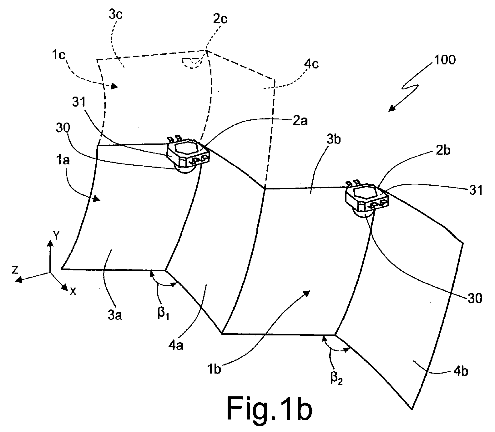
- figure 1b shows a reflective optical system 100 of the "complex" type comprising a plurality of light sources 2a,2b,2c, each operationally associated with a first reflecting surface, respectively 3a,3b,3c and with a second reflecting surface 4a,4b,4c, to form therewith a single lighting "module" 1a,1b,1c, so that the optical system 100 is made up of a plurality of lighting modules 1a,1b,1c, mutually juxtaposed in a mono-dimensional matrix arrangement (i.e.
- the reflecting surfaces 3a,b,c, and 4a,b,c can be identical or, generally, not identical but with different equations and shapes, depending on the desired brightness distribution, and, likewise, the angles ⁇ 1 and ⁇ 2 can be identical or different.
- the sources 2 that are used comprise photoemitting means 30 selected from the group comprising: incandescent lamps; gas discharge lamps; monochromatic LEDs; polychromatic LEDs; and preferably consist of LEDs 30 suitable to emit a luminous flux of at least 10 lumens for a white light LED and 3 lumens for a red or orange light LED, mounted on at least one printed circuit board 31.
- a further alternative embodiment of the invention instead of consisting of one or more "basic” modules 1 possibly connected in a matrix arrangement, as illustrated in figure 1b , it can consist of one or more "basic” modules 200 ( figure 2 ), in which the reflecting surfaces 3 and 4 which are arranged obliquely in relation to one another at an angle ⁇ such as to subtend a concavity 5 delimited between said surfaces 3 and 4, are associated with a light source 202 comprising photoemitting means such as a LED 30 borne by a relative printed circuit board 31 and a light guide 203 (for example consisting of a fiber optic or a fiber optic bundle), of which a first end 204 is arranged on a axis with the optical axis A and of which a second end 205 is arranged remotely in relation to the first and is connected to the photoemitting means 30.
- a light source 202 comprising photoemitting means such as a LED 30 borne by a relative printed circuit board 31 and a light guide 203 (for
- the "basic modules" or systems 200 can of course also be connected to one another (or to basic modules 1) to form complex systems of the type of system 100 in figure 1b .
- one or more reflective optical systems 1, 100 and/or 200 can be incorporated into a lighting device 400 generally comprising an element 401 made of a synthetic plastic material or metal and fixable in a known way to the body of a vehicle (or to the inside of the body of a headlight), for example a motor vehicle which is not illustrated for the sake of simplicity, and at least one transparent fluid-tight sealing element 402 to close an opening 404 of the cup-shaped element 401, in which the optical system 1 and/or 100 and/or 200 is arranged and housed inside the cup-shaped element 401 in a position oriented towards the opening 404 and such that the optical axis B intercepts the transparent closing element 402 and when in use is directly parallel to a direction in which the vehicle is travelling.
- a lighting device 400 generally comprising an element 401 made of a synthetic plastic material or metal and fixable in a known way to the body of a vehicle (or to the inside of the body of a headlight), for example a motor vehicle which is not illustrated for the sake of simplicity, and
- the printed circuit board 31 is provided, on-board, with a single LED 30 ( figure 4a ) or with a plurality of LEDs 30b,30c,30d ( figure 4b ) which are possibly selectively activatable; in any case the printed circuit board 31 is attached to a mounting surface 405 of the cup-shaped element 401, which is generally obtained on a side wall, preferably an upper wall 406 of said cup-shaped element 401 and so that the first optical axis A is arranged perpendicularly to the mounting surface 405 (clearly, in case of the system 200, an optical axis C of the LED 30 is perpendicular to the mounting surface 405).
- the generic light source 2 (or 202) also comprises electronic control means 500, preferably mounted directly on-board the printed circuit board 31, suitable to selectively activate/deactivate the single LED 30 (in case of the source 2 - figure 4a ) or one LED 30b,30c,30d at a time (in case of a source 2' - figure 4b ) of said plurality of selectively activatable LEDs 30.
- electronic control means 500 preferably mounted directly on-board the printed circuit board 31, suitable to selectively activate/deactivate the single LED 30 (in case of the source 2 - figure 4a ) or one LED 30b,30c,30d at a time (in case of a source 2' - figure 4b ) of said plurality of selectively activatable LEDs 30.
- the light source 2,2',202 is produced in such a way that said first and second surfaces 3,4 of a "basic module" 1 or 200 can be operationally associated, selectively, with different LEDs, for example 30b,30c,30d; and in such a way that, in case of a lighting device 400 such as that illustrated in figure 6 , in which a single cup-shaped element 401 contains a plurality of first and second surfaces, respectively 3a,3b and 4a,4b, each operationally associated with a different LED 30a,30b, each LED 30 can be selectively activated according to a previously defined sequence.
- the device 400 is a headlight and, in this case, the association of a pair of basic optical systems 1a,1b in a single element 401 with suitable electronic control means 500 is used to progressively illuminate different angular sectors (for example of a bend in the road) in relation to the direction in which the vehicle is travelling (SBL function).
- the gradual activation or deactivation of the lighting element and the possibility of obtaining different brightness levels can also be achieved by using a PWM signal to modulate the current absorbed by the lighting module.
- lighting devices of the type of the device 400 which are multifunction devices, capable of being used indifferently as headlights or lamps (for example rear lights), depending on the shape and position of the pairs of reflecting surfaces arranged at an oblique angle in relation to one another that are used each time in association with a single LED (or a plurality or battery of LEDs mounted adjacently on a single printed circuit board, as in figure 4b ).
- the printed circuit board 31 is in all versions of the system 1, 100, 200 associated with heat dissipation means 550 ( figure 6 ), preferably mounted on the outside, for example above and to the rear, of the cup-shaped element 401.
- the LEDs 30 are preferably mounted "face-down" or in a DLA arrangement, as schematically illustrated in figures 4a and 4b , in which the printed circuit board 31 is mounted on an upper side surface 406 of the cup-shaped element 401, with the single LED 30 or battery of LEDs 30b,30c,30d face-down and so as in any case to distribute brightness with a bright-dark cut-off line L, as illustrated in figure 3 ; in this way the optical system according to the invention is used to perform functions that require a well-defined cut-off line, such as dipped-beam headlights or fog lights, or with a dual function (dipped-beam and fog lights).
- a well-defined cut-off line such as dipped-beam headlights or fog lights, or with a dual function (dipped-beam and fog lights).
- Said "face-down" or DLA arrangement of the LEDs 30 also means that the optical system according to the invention can be used with the printed circuit board 31 mounted on the upper side surface 406 of the cup-shaped element 401, with the single LED 30 or battery of LEDs 30b,30c,30d face-down and associated with heat dissipation means 550 arranged on the rear of the cup-shaped element 401 and directly connected to at least one component element 560 ( figure 4 ) of the printed circuit board 31 made of a material with relatively high thermal conductivity.
- the "face-down" or DLA arrangement of the LEDs 30 makes it possible to obtain a better thermal coupling between the printed circuit board 31 and the passive dissipation element 550, when the printed circuit board 31 is produced with an appropriate layout (single face), said thermal coupling comprising conductive tracks 562 on which the dissipation part of the LEDs 30 is mounted and which are attached to an aluminium base 565, with an intermediate heat conducting layer 566 in the form of tape or liquid adhesive, whether the passive dissipation element 550 is arranged close to ( figure 4b ) or at a distance from ( figure 4a ) the tracks 562; the dissipation element 550 can be a specific, finned element, as in figure 6 , or (alternatively or in addition) it can be said reflector 600 ( figure 6 ) consisting of a single piece (or several pieces assembled together).
- a lighting device such as the device 400, is thus characterized by the presence of at least one reflector the whole of which is oriented towards a transparent closing element 402, which may or may not have optical functions and is possibly provided with an intermediate auxiliary optical element 20, divided along at least a meridian thereof and by means of at least one edge in at least a pair of adjacent reflecting surfaces arranged at an oblique angle in relation to one another so as to between them delimit a dihedral angle and having a structure such as to define an optical axis B of the reflector arranged essentially perpendicularly to a plane through which the optical axis (A) of the light source used each time passes.
- control electronics can be mounted on the printed circuit board 31 on which the LEDs are mounted, in order to implement a highly compact plug&play system.
Landscapes
- Engineering & Computer Science (AREA)
- General Engineering & Computer Science (AREA)
- Physics & Mathematics (AREA)
- Microelectronics & Electronic Packaging (AREA)
- Optics & Photonics (AREA)
- Non-Portable Lighting Devices Or Systems Thereof (AREA)
Abstract
Description
- The present invention relates to a modular reflective optical lighting system, and a lighting device equipped therewith, in particular a vehicle light or headlight, wherein the desired brightness distribution is achieved, among other things, by juxtaposing inside a single body two or more modular optical systems comprising the same "basic" components, the latter being more or less identical to one another.
- It is known that the lighting devices used in vehicles, especially motor vehicles, are required to perform increasingly complex and demanding functions, for example daytime lighting, or DRL (the Daytime Running Light function) and progressive illumination of bends (cornering) while at the same time they must be smaller in size, in order to reduce their overall dimensions and weight. One solution offered by modern technology consists for example of using solid-state light sources or LEDs, which reduce both the amount of energy that is used and the amount of heat that is generated during their use, which is one of the greatest limits of traditional incandescent light sources (bulbs).
-
WO2007069123 for example relates to a vehicle dipped-beam headlight that is provided with a solid-state light source (LED). - Here and in the following description, the term "light source" refers to any light source (LED, incandescent lamp, discharge lamp, etc.) in which the light rays that are emitted can be approximated as ideally radiating from a single point, for example, in case of incandescent lamps, from the middle of the filament. This definition therefore excludes light sources such as neon tubes, in which the light rays are radiated from a plurality of adjacent points arranged along an axis.
- The headlight described in
WO2007069123 , while using a LED as the light source, is relatively large and complex, due to the need to overcome a series of practical design problems associated with the use of a single solid-state light source that is sufficiently powerful to achieve the brightness distribution required by a headlight. -
DE19820267 describes a reflective optical lighting system that uses a LED light source and achieves uniform distribution of the emitted light in a system with limited overall dimensions; said optical system is based on the connection of the light source with a reflector consisting of a convex element the convexity of which lies in the main direction of emission of the light source; the convex element can consist of a curved surface or of two reflecting surfaces of any shape (flat, concave or convex) joined together at an angle. This type of optical system, conceived for the rear illumination of a display, for example a liquid crystal display, can in theory also be used for vehicle lighting devices, but in that case its use would clearly be limited to lamps only. - The purpose of the present invention is therefore to provide a reflective optical lighting system with reduced overall dimensions that is suitable to use light sources consisting of LEDs, as in the case of the optical system described in
DE19820267 , but which is more versatile and in particular can be used indifferently to produce lamps and headlights and can therefore be used in the manufacture of indicator and lighting devices for vehicles that are cheap to produce, light in weight, have reduced overall dimensions and low electricity consumption, possibly with a single device incorporating a multitude of different optical functions, thus overcoming the limits of the prior art. - According to the present invention a reflective optical system is provided as set forth in
claim 1. - In particular, the reflective optical lighting system according to the invention comprises at least one light source having a first optical axis defining a main direction of radiation of light rays emitted by said source and at least a first and a second reflecting surface operationally associated with the light source to intercept the light rays and arranged so as to form between them a first pre-defined angle of a size other than 180°; unlike in
DE19820267 , however, the first and second reflecting surfaces delimit, between them, a concavity oriented towards the light source and are shaped so that, when in use, said concavity receives a substantial portion of said light rays emitted by the source to reflect them in a direction forming with the first optical axis a second angle of a pre-defined size, so that the reflected rays present a main direction of radiation defined by a second optical axis essentially perpendicular to the first. - The light source that is used is preferably a Lambertian light source and in that case the concavity defined between the first and the second reflecting surfaces and oriented towards the light source occupies a solid angle greater than n steradians, i.e. greater than a quarter of the solid spherical angle, and in any case such that at least 30% of the light rays emitted by the source are intercepted by the first and second reflecting surfaces.
- The optical system according to the invention can also comprise at least one bright, clear or coloured secondary optical element, operationally associated with the first and second reflecting surfaces in the direction defined by the second optical axis and consisting of at least a lens or a matrix of micro-optics arranged transversely to the second optical axis.
- Lastly, the optical system according to the invention can comprise a plurality of light sources, each operationally associated with a first and second reflecting surface to form therewith a single lighting module so that said system consists of a plurality of lighting modules mutually juxtaposed in a one-dimensional or two-dimensional matrix arrangement.
- The invention also relates to a lighting device comprising a cup-shaped element, preferably made of plastic or metal and fixable to the body of a vehicle, and at least a transparent fluid-tight sealing element to close an opening in the cup-shaped element in which said optical system is arranged and housed in a position oriented towards the opening and such that the second optical axis intercepts the transparent closing element and when used is directly parallel to a direction in which the vehicle is travelling.
- Thus, a similar process can be used to produce both headlights (in particular those intrinsically incorporating a bright-dark or cut-off line such as main-beam headlights or fog lights, in which the light source, in particular a LED light source, is assembled face-down - hereinafter referred to as DLA, for "Down LED Assembly" - so that the parasite rays illuminate the road and are not dispersed upwards), and indicator lights (position or direction indicators, etc.)
- It is also possible to produce lighting devices that consist of a single "basic" optical module, comprising a light source and the two reflecting surfaces associated therewith joined at an angle of approximately 90° depending on the desired brightness distribution (symmetric or asymmetric). A "basic" module can be connected vertically or horizontally to one or more identical or similar modules, in order to obtain a complex system, which allows the use of particular types of activation logic, for example to activate the different modules gradually as a function of the steering angle of the vehicle (the "Static Bend Lighting" function).
- The light sources can be incandescent lamps or solid-state sources (LEDs). The LEDs can be SMDs (Surface Mounted Devices) or dies (semiconductors only), possibly in a matrix arrangement. If several chips are used in the same basic module for example, different coloured lights can be obtained, using the same pair of angled reflecting surfaces for different functions, by appropriately mixing the contributions deriving from different monochromatic LED sources. For example, using RGB (Red Green Blue) LEDs, the same function can be used for the direction indicator, DRL and particular sectors of the dipped-beam / main-beam functions.
- Possible fields of application for the present invention are therefore headlights or lamps for cars, both to implement indicator functions (direction indicators, DRL, position indicators, side markers) and lighting functions (dipped-beam, main-beam, fog lights, SBL).
- Further characteristics and advantages of the present invention will become clear from the following description of the non-limiting embodiments thereof, with reference to the drawings attached hereto, in which:
-
figure 1a schematically illustrates a front three-quarter perspective view of the structure of a "basic" optical system according to the present invention; -
figure 1b shows the same view asfigure 1a , but in case of a complex optical system, consisting of several juxtaposed modules each consisting of a "basic" system; -
figure 2 shows the same view asfigure 1a in case of a "basic" indirect or "remote" lighting system; -
figures 3a and 3b schematically illustrate possible alternative configurations of the "basic" system infigure 1a and the relative symmetric or asymmetric brightness distribution that can be obtained on a screen 10 m away in the standard photometric test; -
figures 4a and 4b are schematic orthogonal elevations of two alternative embodiments of the luminous source of the optical system according to the invention; -
figure 5 is an elevation and longitudinal section view along the optical axis of the basic optical system infigure 1a ; and -
figure 6 illustrates a front three-quarter perspective view of a vehicle headlight incorporating an optical lighting system according to the invention. - With reference to
figure 1a ,reference number 1 indicates a reflective optical lighting system comprising at least onelight source 2 and at least a first reflectingsurface 3 and a second reflectingsurface 4 operationally associated with thelight source 2 and arranged obliquely in relation to one another; in particular, thelight source 2 has a first optical axis A defining a main direction of radiation of light rays R emitted by saidsource 2 and thereflecting surfaces - According to a first and fundamental aspect of the invention, the reflecting
surfaces concavity 5 oriented towards thelight source 2 and are shaped so that when in use saidconcavity 5 receives a substantial portion of the light rays R emitted by thesource 2 to reflect them in a direction forming with the optical axis A an angle α (figure 5 ) of a preset size, so that the reflected rays r present a main direction of radiation defined by a second optical axis B, essentially perpendicular to the optical axis A. - According to the invention, the angle β between the two reflecting
surfaces figures 3a and 3b ) said angle is respectively less than 90° (figure 3b ) or more than 90° (figure 3a ), thus achieving a respectively asymmetric and symmetric brightness distribution of the reflected rays r with respect to the optical axis B. - With reference to
figure 5 , the size of the angle α can be between 50° and 150° and, more preferably, it is between the values α1 of 85° and α2 of 100°. Moreover, the reflectiveoptical system 1 described herein preferably comprises, for each first and second reflectingsurface single light source 2, at least a third reflecting surface 10 (figure 5 ) and/or 11 (figure 1a ) oriented towards theconcavity 5 and in any case arranged essentially perpendicularly to the optical axis A, in order to also produce in the direction defined by the optical axis B reflected rays r' (figure 5 ) which have undergone a double reflection, for example so as to send almost all of the light rays R emitted by thesource 2 below a bright-dark cut-off mark L (figure 3 ). - The
light source 2 is preferably, but not necessarily, a Lambertian light source and theconcavity 5 defined between the reflectingsurfaces light source 2 occupies a solid angle greater than n steradians, i.e. greater than a quarter of the solid spherical angle, and in any case such that at least 30% of the light rays R emitted by thesource 2 are intercepted by the reflectingsurfaces - Lastly, the
optical system 1 described herein can also comprise (figure 1a ) at least one bright, clear or coloured secondaryoptical element 20, operationally associated with the reflectingsurfaces - According to the possible and preferred embodiment illustrated in
figure 1b , a reflectiveoptical system 100 according to the invention can be achieved by combining several "elementary"optical systems 1, which can be identical or not to one another. - In particular,
figure 1b shows a reflectiveoptical system 100 of the "complex" type comprising a plurality oflight sources surface optical system 100 is made up of a plurality oflighting modules pairs matrix - Clearly, in that case, the
reflecting surfaces 3a,b,c, and 4a,b,c can be identical or, generally, not identical but with different equations and shapes, depending on the desired brightness distribution, and, likewise, the angles β1 and β2 can be identical or different. - In all cases, the
sources 2 that are used comprise photoemitting means 30 selected from the group comprising: incandescent lamps; gas discharge lamps; monochromatic LEDs; polychromatic LEDs; and preferably consist ofLEDs 30 suitable to emit a luminous flux of at least 10 lumens for a white light LED and 3 lumens for a red or orange light LED, mounted on at least one printedcircuit board 31. - According to a further alternative embodiment of the invention, instead of consisting of one or more "basic"
modules 1 possibly connected in a matrix arrangement, as illustrated infigure 1b , it can consist of one or more "basic" modules 200 (figure 2 ), in which the reflectingsurfaces concavity 5 delimited between saidsurfaces light source 202 comprising photoemitting means such as aLED 30 borne by a relative printedcircuit board 31 and a light guide 203 (for example consisting of a fiber optic or a fiber optic bundle), of which afirst end 204 is arranged on a axis with the optical axis A and of which asecond end 205 is arranged remotely in relation to the first and is connected to the photoemitting means 30. - The "basic modules" or
systems 200 can of course also be connected to one another (or to basic modules 1) to form complex systems of the type ofsystem 100 infigure 1b . - With reference to
figure 6 , one or more reflectiveoptical systems lighting device 400 generally comprising anelement 401 made of a synthetic plastic material or metal and fixable in a known way to the body of a vehicle (or to the inside of the body of a headlight), for example a motor vehicle which is not illustrated for the sake of simplicity, and at least one transparent fluid-tight sealing element 402 to close an opening 404 of the cup-shaped element 401, in which theoptical system 1 and/or 100 and/or 200 is arranged and housed inside the cup-shaped element 401 in a position oriented towards the opening 404 and such that the optical axis B intercepts thetransparent closing element 402 and when in use is directly parallel to a direction in which the vehicle is travelling. - Depending on the type of
optical system circuit board 31 is provided, on-board, with a single LED 30 (figure 4a ) or with a plurality ofLEDs figure 4b ) which are possibly selectively activatable; in any case the printedcircuit board 31 is attached to amounting surface 405 of the cup-shaped element 401, which is generally obtained on a side wall, preferably anupper wall 406 of said cup-shaped element 401 and so that the first optical axis A is arranged perpendicularly to the mounting surface 405 (clearly, in case of thesystem 200, an optical axis C of theLED 30 is perpendicular to the mounting surface 405). - Moreover, according to an alternative and preferred embodiment, (
figure 4 ) the generic light source 2 (or 202) also comprises electronic control means 500, preferably mounted directly on-board the printedcircuit board 31, suitable to selectively activate/deactivate the single LED 30 (in case of the source 2 -figure 4a ) or oneLED figure 4b ) of said plurality of selectivelyactivatable LEDs 30. - In particular, the
light source second surfaces lighting device 400 such as that illustrated infigure 6 , in which a single cup-shaped element 401 contains a plurality of first and second surfaces, respectively 3a,3b and 4a,4b, each operationally associated with adifferent LED LED 30 can be selectively activated according to a previously defined sequence. In the example illustrated infigure 6 , thedevice 400 is a headlight and, in this case, the association of a pair of basicoptical systems single element 401 with suitable electronic control means 500 is used to progressively illuminate different angular sectors (for example of a bend in the road) in relation to the direction in which the vehicle is travelling (SBL function). - The gradual activation or deactivation of the lighting element and the possibility of obtaining different brightness levels can also be achieved by using a PWM signal to modulate the current absorbed by the lighting module.
- Clearly, on the basis of the description herein, it is possible to produce lighting devices of the type of the
device 400, but which are multifunction devices, capable of being used indifferently as headlights or lamps (for example rear lights), depending on the shape and position of the pairs of reflecting surfaces arranged at an oblique angle in relation to one another that are used each time in association with a single LED (or a plurality or battery of LEDs mounted adjacently on a single printed circuit board, as infigure 4b ). - According to a final but equally important characteristic of the invention, the printed
circuit board 31 is in all versions of thesystem figure 6 ), preferably mounted on the outside, for example above and to the rear, of the cup-shaped element 401. - In particular the
LEDs 30 are preferably mounted "face-down" or in a DLA arrangement, as schematically illustrated infigures 4a and 4b , in which the printedcircuit board 31 is mounted on anupper side surface 406 of the cup-shaped element 401, with thesingle LED 30 or battery ofLEDs figure 3 ; in this way the optical system according to the invention is used to perform functions that require a well-defined cut-off line, such as dipped-beam headlights or fog lights, or with a dual function (dipped-beam and fog lights). - Said "face-down" or DLA arrangement of the
LEDs 30 also means that the optical system according to the invention can be used with the printedcircuit board 31 mounted on theupper side surface 406 of the cup-shaped element 401, with thesingle LED 30 or battery ofLEDs shaped element 401 and directly connected to at least one component element 560 (figure 4 ) of the printedcircuit board 31 made of a material with relatively high thermal conductivity. - In particular, the "face-down" or DLA arrangement of the
LEDs 30 makes it possible to obtain a better thermal coupling between the printedcircuit board 31 and thepassive dissipation element 550, when the printedcircuit board 31 is produced with an appropriate layout (single face), said thermal coupling comprisingconductive tracks 562 on which the dissipation part of theLEDs 30 is mounted and which are attached to analuminium base 565, with an intermediate heat conductinglayer 566 in the form of tape or liquid adhesive, whether thepassive dissipation element 550 is arranged close to (figure 4b ) or at a distance from (figure 4a ) thetracks 562; thedissipation element 550 can be a specific, finned element, as infigure 6 , or (alternatively or in addition) it can be said reflector 600 (figure 6 ) consisting of a single piece (or several pieces assembled together). - A lighting device according to the invention, such as the
device 400, is thus characterized by the presence of at least one reflector the whole of which is oriented towards atransparent closing element 402, which may or may not have optical functions and is possibly provided with an intermediate auxiliaryoptical element 20, divided along at least a meridian thereof and by means of at least one edge in at least a pair of adjacent reflecting surfaces arranged at an oblique angle in relation to one another so as to between them delimit a dihedral angle and having a structure such as to define an optical axis B of the reflector arranged essentially perpendicularly to a plane through which the optical axis (A) of the light source used each time passes. - On the basis of the description herein, there is no need to use printed circuit boards with high thermal properties even for the electronic power components, in particular LEDs. Any control electronics (such as the control means 500) can be mounted on the printed
circuit board 31 on which the LEDs are mounted, in order to implement a highly compact plug&play system. - In conclusion, the system according to the invention is characterized by the following elements:
- the optical axis A of the sources used is perpendicular to the
mounting surface 405 of theprinted circuit board 31, which forms an angle of between α1 (50°) and α2 (150°), in particular between 85° and 100°, in relation to the main direction (B) of emission of the reflector; - the coupling between the passive
heat dissipation element 550 and the weld side of the printedcircuit board 31, on which the LED sources are mounted, which allows low-cost power LEDs and printed circuit boards to be used (such as the single-face type in FR4, CEM, etc,).
Claims (26)
- Reflective optical lighting system (1;100;200) comprising at least one light source (2) having a first optical axis (A) defining a main direction of radiation of light rays emitted by said source and at least a first (3) and a second (4) reflecting surface operationally associated with the light source (2) to intercept said light rays and arranged so as to form between them a first preset angle (β) of a size other than 180°, characterized in that the first and second reflecting surfaces (3,4) between them delimit a concavity (5) oriented towards the light source and are shaped so that, when in use, said concavity receives a substantial portion of said light rays emitted by said source to reflect them in a direction forming with the first optical axis (A) a second angle (α) of a preset size so that the reflected rays present a main direction of radiation defined by a second optical axis (B) approximately perpendicular to the first.
- Optical system according to claim 1, characterized in that said first angle of a preset size (β) is 90° or in the region of 90°.
- Optical system according to claim 1, characterized in that said first angle of a preset size (β) is less than 90°.
- Optical system according to claim 1, characterized in that said first angle of a preset size (β) is more than 90°.
- Optical system according to any of the previous claims, characterized in that said first and second reflecting surfaces (3,4) are shaped so as to distribute the reflected light rays symmetrically in relation to said second optical axis (B).
- Optical system according to any of the claims from 1 to 4, characterized in that said first and second reflecting surfaces (3,4) are shaped so as to distribute the reflected light rays asymmetrically in relation to said second optical axis (B).
- Optical system according to any of the previous claims, characterized in that said second angle (α) of a preset size is preferably between 50° and 150° and, more preferably, between 85° and 100°.
- Optical system according to any of the previous claims, characterized in that it comprises, for each first and second reflecting surface (3,4) associated with a said light source, at least a third reflecting surface (10;11) oriented towards said concavity (5) and arranged essentially perpendicularly to said first optical axis (A).
- Optical system according to any of the previous claims, characterized in that said light source (2) is a Lambertian source.
- Optical system according to claim 9, characterized in that said concavity (5) defined between said first and second reflecting surfaces (3,4) is oriented towards said light source (2) and occupies a solid angle greater than n steradians, i.e. greater than a quarter of the solid spherical angle, and in any case such that at least 30% of the light rays emitted by said source are intercepted by said first and second reflecting surfaces (3,4).
- Optical system according to any of the previous claims, characterized in that it also comprises at least one bright, clear or coloured secondary optical element (20), operationally associated with said first and second reflecting surfaces (3,4) in the direction defined by said second optical axis (B); said at least one secondary optical element (20) consisting of at least a lens or a matrix of micro-optics.
- Optical system (100) according to any of the previous claims, characterized in that it comprises a plurality of light sources (2a,b,c), each operationally associated with one of said first (3a,b,c) and second (4a,b,c) reflecting surfaces so as to form therewith a single lighting module (1a,b,c) so that said optical system is made up of a plurality of said lighting modules (2a,b,c) mutually juxtaposed in a one-dimensional (X,Y) or two-dimensional (XY) matrix arrangement.
- Optical system according to any of the previous claims, characterized in that said light source (2) comprises photoemitting means chosen from the group consisting in: incandescent lamps; gas discharge lamps, monochromatic LEDs; polychromatic LEDs.
- Optical system according to claim 13, characterized in that said light source (2) comprises at least one LED (30) suitable to emit a luminous flux of at least 10 lumens for a white light LED and 3 lumens for a red or orange light LED.
- Optical system (200) according to claim 13 or 14, characterized in that said light source also comprises a light guide (203) of which a first end (204) is arranged on-axis with said first optical axis and of which a second end (205) is arranged remotely in relation to the first and is connected to said photoemitting means.
- Lighting device (400) comprising a cup-shaped element (401), preferably made of a synthetic plastic material and fixable to the body of a vehicle or to the inside of the body of a headlight also made of synthetic material, and at least one transparent fluid-tight sealing element (402) to close an opening (404) of the cup-shaped element; characterized in that it also comprises an optical system (1;100;200) according to any of the previous claims arranged and housed inside the cup-shaped element (401) in a position oriented towards the opening (404) and such that the second optical axis (B) intercepts said transparent closing element (402) and when in use is directly parallel to a direction in which the vehicle is travelling.
- Lighting device (400) according to claim 16, characterized in that said at least one light source comprises a printed circuit board (31) provided on-board with a single LED (30) or a plurality of selectively activatable LEDs (30a,b,c); the printed circuit board (31) being attached to a mounting surface (405) of the cup-shaped element.
- Lighting device according to claim 17, characterized in that said mounting surface (405) is obtained on a side wall (406), preferably an upper wall, of said cup-shaped element and in such a way that said first optical axis (A) is arranged perpendicularly to said mounting surface (405).
- Lighting device according to claim 17 or 18, characterized in that said at least one light source (2) also comprises electronic control means (500), preferably mounted directly on-board said printed circuit board (31).
- Lighting device according to claim 19, characterized in that said electronic control means (500) are suitable to selectively activate/deactivate said single LED (30) or one LED (30a,b,c) at a time of said plurality of selectively activatable LEDs, so that said first and second surfaces (3a,3b;4a,4b) can be operationally associated, selectively, with different LEDs (30a,b); and in such a way that, in case of the presence in a single element (401) of a plurality of first and second surfaces (3,4) each operationally associated with a different LED, each LED (30) can be selectively activated according to a previously defined sequence, for example to progressively illuminate different angular sectors with respect to the direction in which the vehicle is travelling.
- Lighting device according to claim 19 or 20, characterized in that said printed circuit board (31) is associated with heat dissipation means (550) provided on said cup-shaped element.
- Use of a lighting device (400) according to claim 20 as a vehicle headlight (or parts thereof).
- Use of a lighting device (400) according to claim 20 as a lamp, in particular the rear light of a vehicle.
- Use according to claim 22, wherein said printed circuit board (31) is mounted on an upper side surface (406) of the cup-shaped element, with said single LED (30) or plurality of LEDs (30a,b,c,) face-down and so as to distribute brightness with a bright-dark cut-off line.
- Use according to claim 22 or 23, wherein said printed circuit board (31) is mounted on an upper side surface (406) of the cup-shaped element, with said single LED (30) or plurality of LEDs (30a,b,c) face-down, and is associated with heat dissipation means (550) arranged on the rear of the cup-shaped element and directly connected to a component element (560) of said printed circuit board made of a material with relatively high thermal conductivity.
- Use according to claim 25, characterized in that said printed circuit board (31) is a single-face circuit and is thermally coupled to a passive dissipation element (550) between a weld side of the printed circuit board (30) and the passive dissipation element (550) by means of a thermal interface (566) in the form of tape or liquid adhesive.
Priority Applications (1)
| Application Number | Priority Date | Filing Date | Title |
|---|---|---|---|
| EP07425625.6A EP2045514B2 (en) | 2007-10-05 | 2007-10-05 | Modular reflective optical lighting system and lighting device equipped therewith, in particular for vehicles |
Applications Claiming Priority (1)
| Application Number | Priority Date | Filing Date | Title |
|---|---|---|---|
| EP07425625.6A EP2045514B2 (en) | 2007-10-05 | 2007-10-05 | Modular reflective optical lighting system and lighting device equipped therewith, in particular for vehicles |
Publications (3)
| Publication Number | Publication Date |
|---|---|
| EP2045514A1 true EP2045514A1 (en) | 2009-04-08 |
| EP2045514B1 EP2045514B1 (en) | 2015-12-09 |
| EP2045514B2 EP2045514B2 (en) | 2022-02-16 |
Family
ID=39106173
Family Applications (1)
| Application Number | Title | Priority Date | Filing Date |
|---|---|---|---|
| EP07425625.6A Ceased EP2045514B2 (en) | 2007-10-05 | 2007-10-05 | Modular reflective optical lighting system and lighting device equipped therewith, in particular for vehicles |
Country Status (1)
| Country | Link |
|---|---|
| EP (1) | EP2045514B2 (en) |
Cited By (8)
| Publication number | Priority date | Publication date | Assignee | Title |
|---|---|---|---|---|
| EP2503225A2 (en) | 2011-03-24 | 2012-09-26 | Automotive Lighting Reutlingen GmbH | Motor vehicle lighting device and motor vehicle headlamp with such a lighting device |
| EP2863108A3 (en) * | 2013-10-07 | 2015-11-25 | Automotive Lighting Reutlingen GmbH | LED module of a motor vehicle headlamp |
| WO2016008897A1 (en) * | 2014-07-15 | 2016-01-21 | Koninklijke Philips N.V. | Vehicle lighting module |
| WO2016041675A1 (en) * | 2014-09-16 | 2016-03-24 | Volkswagen Aktiengesellschaft | Vehicle lamp and method for providing a light function by means of a vehicle lamp |
| CN105473934A (en) * | 2013-08-08 | 2016-04-06 | 皇家飞利浦有限公司 | Universal daytime running lights for motor vehicles |
| WO2016124664A1 (en) * | 2015-02-06 | 2016-08-11 | Valeo Vision | Reflector device for a light module with electromagnetic shielding |
| IT201600124320A1 (en) * | 2016-12-09 | 2018-06-09 | Olsa Spa | OPTICAL SYSTEM WITH MULTIPLE FUNCTIONALITY |
| WO2020192858A1 (en) * | 2019-03-27 | 2020-10-01 | HELLA GmbH & Co. KGaA | Lighting device for vehicles |
Citations (4)
| Publication number | Priority date | Publication date | Assignee | Title |
|---|---|---|---|---|
| US5396407A (en) * | 1991-11-26 | 1995-03-07 | Stanley Electric Co., Ltd. | Headlight for irradiating light beam for a vehicle passing by in the opposite direction |
| DE19820267A1 (en) | 1998-05-07 | 1999-11-11 | Valeo Electronics Gmbh & Co Kg | Reflector housing for rear illumination of flat display |
| DE102004025699A1 (en) * | 2003-06-06 | 2005-01-05 | Zizala Lichtsysteme Gmbh | Vehicle head-lamp has auxiliary reflector in lower/upper region of deflection reflector in upper/lower region of main reflector to reflect light from deflection reflector to region in front of vehicle |
| WO2007069123A2 (en) | 2005-12-12 | 2007-06-21 | Philips Intellectual Property & Standards Gmbh | Led collimator element for a vehicle headlight with a low-beam function |
Family Cites Families (4)
| Publication number | Priority date | Publication date | Assignee | Title |
|---|---|---|---|---|
| DE10236825A1 (en) † | 2002-08-10 | 2004-04-01 | Hella Kg Hueck & Co. | Lighting unit for motor vehicles |
| US7377671B2 (en) * | 2003-02-04 | 2008-05-27 | Light Prescriptions Innovators, Llc | Etendue-squeezing illumination optics |
| JP4044024B2 (en) † | 2003-09-29 | 2008-02-06 | 株式会社小糸製作所 | Vehicle headlamp |
| DE102006041942A1 (en) † | 2006-09-07 | 2008-03-27 | Hella Kgaa Hueck & Co. | Projection headlight for vehicle, has reflector devices extending in area between extension level of respective light source device and optical axis of lens, where light source devices are attached to respective reflector devices |
-
2007
- 2007-10-05 EP EP07425625.6A patent/EP2045514B2/en not_active Ceased
Patent Citations (4)
| Publication number | Priority date | Publication date | Assignee | Title |
|---|---|---|---|---|
| US5396407A (en) * | 1991-11-26 | 1995-03-07 | Stanley Electric Co., Ltd. | Headlight for irradiating light beam for a vehicle passing by in the opposite direction |
| DE19820267A1 (en) | 1998-05-07 | 1999-11-11 | Valeo Electronics Gmbh & Co Kg | Reflector housing for rear illumination of flat display |
| DE102004025699A1 (en) * | 2003-06-06 | 2005-01-05 | Zizala Lichtsysteme Gmbh | Vehicle head-lamp has auxiliary reflector in lower/upper region of deflection reflector in upper/lower region of main reflector to reflect light from deflection reflector to region in front of vehicle |
| WO2007069123A2 (en) | 2005-12-12 | 2007-06-21 | Philips Intellectual Property & Standards Gmbh | Led collimator element for a vehicle headlight with a low-beam function |
Cited By (20)
| Publication number | Priority date | Publication date | Assignee | Title |
|---|---|---|---|---|
| EP2503225A3 (en) * | 2011-03-24 | 2016-08-17 | Automotive Lighting Reutlingen GmbH | Motor vehicle lighting device and motor vehicle headlamp with such a lighting device |
| DE102011006073A1 (en) | 2011-03-24 | 2012-09-27 | Automotive Lighting Reutlingen Gmbh | Automotive lighting device and motor vehicle headlight with such a lighting device |
| EP2503225A2 (en) | 2011-03-24 | 2012-09-26 | Automotive Lighting Reutlingen GmbH | Motor vehicle lighting device and motor vehicle headlamp with such a lighting device |
| CN105473934B (en) * | 2013-08-08 | 2018-03-30 | 皇家飞利浦有限公司 | Universal daytime running lights for motor vehicles |
| EP3044499B1 (en) * | 2013-08-08 | 2020-09-16 | Lumileds Holding B.V. | Universal daytime running lamp for automotive vehicles |
| CN105473934A (en) * | 2013-08-08 | 2016-04-06 | 皇家飞利浦有限公司 | Universal daytime running lights for motor vehicles |
| US10473287B2 (en) | 2013-08-08 | 2019-11-12 | Koninklijke Philips N.V. | Universal daytime running lamp for automotive vehicles |
| US10060593B2 (en) | 2013-08-08 | 2018-08-28 | Koninklijke Philips N.V. | Universal daytime running lamp for automotive vehicles |
| EP2863108A3 (en) * | 2013-10-07 | 2015-11-25 | Automotive Lighting Reutlingen GmbH | LED module of a motor vehicle headlamp |
| WO2016008897A1 (en) * | 2014-07-15 | 2016-01-21 | Koninklijke Philips N.V. | Vehicle lighting module |
| US10386032B2 (en) | 2014-07-15 | 2019-08-20 | Koninklijke Philips N.V. | Vehicle lighting module |
| CN107076381A (en) * | 2014-09-16 | 2017-08-18 | 大众汽车有限公司 | Vehicle lighting device and method for providing a lighting function by means of a vehicle lighting device lamp |
| CN107076381B (en) * | 2014-09-16 | 2019-08-27 | 大众汽车有限公司 | Vehicle lighting device and method for providing a lighting function by means of a vehicle lighting device lamp |
| WO2016041675A1 (en) * | 2014-09-16 | 2016-03-24 | Volkswagen Aktiengesellschaft | Vehicle lamp and method for providing a light function by means of a vehicle lamp |
| FR3032516A1 (en) * | 2015-02-06 | 2016-08-12 | Valeo Vision | DEVICE REFLECTING A LIGHT MODULE WITH ELECTROMAGNETIC SHIELD |
| WO2016124664A1 (en) * | 2015-02-06 | 2016-08-11 | Valeo Vision | Reflector device for a light module with electromagnetic shielding |
| US11193644B2 (en) | 2015-02-06 | 2021-12-07 | Valeo Vision | Reflector device for a light module with electromagnetic shielding |
| IT201600124320A1 (en) * | 2016-12-09 | 2018-06-09 | Olsa Spa | OPTICAL SYSTEM WITH MULTIPLE FUNCTIONALITY |
| WO2020192858A1 (en) * | 2019-03-27 | 2020-10-01 | HELLA GmbH & Co. KGaA | Lighting device for vehicles |
| US11566770B2 (en) | 2019-03-27 | 2023-01-31 | HELLA GmbH & Co. KGaA | Lighting device for vehicles |
Also Published As
| Publication number | Publication date |
|---|---|
| EP2045514B2 (en) | 2022-02-16 |
| EP2045514B1 (en) | 2015-12-09 |
Similar Documents
| Publication | Publication Date | Title |
|---|---|---|
| EP2045514B1 (en) | Modular reflective optical lighting system and lighting device equipped therewith, in particular for vehicles | |
| CN100578076C (en) | Led headlamp system | |
| US7059754B2 (en) | Apparatus and method for providing a modular vehicle light device | |
| US7431486B2 (en) | LED assembly for rear lamps in an automobile | |
| US7441928B2 (en) | Lighting device | |
| CN101592302B (en) | Real loading LED module for motor vehicle rear assembled lamp | |
| KR101500760B1 (en) | Side-loaded LED module of automotive rear combination lamp | |
| US8398283B2 (en) | Automotive signal light employing multi-focal length light pipes | |
| KR102241175B1 (en) | Vehicle led linear lighting module | |
| US20180142852A1 (en) | Light source unit and vehicle front lamp using the light source unit | |
| JP5280087B2 (en) | Equipped flexible electronic support for supporting at least one light emitting diode and method for manufacturing the same | |
| CN103328884A (en) | Lighting apparatus | |
| CN108375048B (en) | Vehicle-mounted lamp | |
| CN104566008A (en) | Lighting system with semiconductor light source module | |
| CN107435882B (en) | lighting device | |
| CN105051451A (en) | Light unit with light output pattern synthesized from multiple light sources and modular refractors | |
| CN116697295A (en) | Integrated vehicle lamp and lens module | |
| CN102425751A (en) | LED automobile headlamp and manufacturing method | |
| US7347604B2 (en) | LED lantern structure | |
| CN105240775A (en) | LED automobile lens adopting light supplementing structure | |
| CN205118890U (en) | Adopt LED car lens of light filling structure | |
| TWI785997B (en) | Integrated vehicle lighting and lens module | |
| CN202432390U (en) | LED (light emitting diode) automobile headlamp | |
| CN103375770A (en) | Reflector of vehicle lighting device and | |
| KR20160053707A (en) | Lamp for vehicle |
Legal Events
| Date | Code | Title | Description |
|---|---|---|---|
| PUAI | Public reference made under article 153(3) epc to a published international application that has entered the european phase |
Free format text: ORIGINAL CODE: 0009012 |
|
| AK | Designated contracting states |
Kind code of ref document: A1 Designated state(s): AT BE BG CH CY CZ DE DK EE ES FI FR GB GR HU IE IS IT LI LT LU LV MC MT NL PL PT RO SE SI SK TR |
|
| AX | Request for extension of the european patent |
Extension state: AL BA HR MK RS |
|
| 17P | Request for examination filed |
Effective date: 20091007 |
|
| 17Q | First examination report despatched |
Effective date: 20091110 |
|
| AKX | Designation fees paid |
Designated state(s): DE FR IT |
|
| RIC1 | Information provided on ipc code assigned before grant |
Ipc: F21S 8/10 20060101AFI20130411BHEP |
|
| RIC1 | Information provided on ipc code assigned before grant |
Ipc: F21V 7/00 20060101AFI20150429BHEP Ipc: F21S 8/10 20060101ALI20150429BHEP Ipc: F21Y 101/02 20060101ALI20150429BHEP |
|
| GRAP | Despatch of communication of intention to grant a patent |
Free format text: ORIGINAL CODE: EPIDOSNIGR1 |
|
| INTG | Intention to grant announced |
Effective date: 20150610 |
|
| GRAS | Grant fee paid |
Free format text: ORIGINAL CODE: EPIDOSNIGR3 |
|
| GRAA | (expected) grant |
Free format text: ORIGINAL CODE: 0009210 |
|
| AK | Designated contracting states |
Kind code of ref document: B1 Designated state(s): DE FR IT |
|
| REG | Reference to a national code |
Ref country code: DE Ref legal event code: R096 Ref document number: 602007044160 Country of ref document: DE |
|
| REG | Reference to a national code |
Ref country code: DE Ref legal event code: R026 Ref document number: 602007044160 Country of ref document: DE |
|
| PLBI | Opposition filed |
Free format text: ORIGINAL CODE: 0009260 |
|
| REG | Reference to a national code |
Ref country code: FR Ref legal event code: PLFP Year of fee payment: 10 |
|
| 26 | Opposition filed |
Opponent name: VALEO VISION Effective date: 20160908 |
|
| PLAX | Notice of opposition and request to file observation + time limit sent |
Free format text: ORIGINAL CODE: EPIDOSNOBS2 |
|
| PLBB | Reply of patent proprietor to notice(s) of opposition received |
Free format text: ORIGINAL CODE: EPIDOSNOBS3 |
|
| REG | Reference to a national code |
Ref country code: FR Ref legal event code: PLFP Year of fee payment: 11 |
|
| APBM | Appeal reference recorded |
Free format text: ORIGINAL CODE: EPIDOSNREFNO |
|
| APBP | Date of receipt of notice of appeal recorded |
Free format text: ORIGINAL CODE: EPIDOSNNOA2O |
|
| APAH | Appeal reference modified |
Free format text: ORIGINAL CODE: EPIDOSCREFNO |
|
| APBM | Appeal reference recorded |
Free format text: ORIGINAL CODE: EPIDOSNREFNO |
|
| APBP | Date of receipt of notice of appeal recorded |
Free format text: ORIGINAL CODE: EPIDOSNNOA2O |
|
| APBQ | Date of receipt of statement of grounds of appeal recorded |
Free format text: ORIGINAL CODE: EPIDOSNNOA3O |
|
| REG | Reference to a national code |
Ref country code: FR Ref legal event code: PLFP Year of fee payment: 12 |
|
| RAP2 | Party data changed (patent owner data changed or rights of a patent transferred) |
Owner name: MARELLI AUTOMOTIVE LIGHTING ITALY S.P.A. |
|
| APBU | Appeal procedure closed |
Free format text: ORIGINAL CODE: EPIDOSNNOA9O |
|
| PUAH | Patent maintained in amended form |
Free format text: ORIGINAL CODE: 0009272 |
|
| STAA | Information on the status of an ep patent application or granted ep patent |
Free format text: STATUS: PATENT MAINTAINED AS AMENDED |
|
| 27A | Patent maintained in amended form |
Effective date: 20220216 |
|
| AK | Designated contracting states |
Kind code of ref document: B2 Designated state(s): DE FR IT |
|
| REG | Reference to a national code |
Ref country code: DE Ref legal event code: R102 Ref document number: 602007044160 Country of ref document: DE |
|
| PGFP | Annual fee paid to national office [announced via postgrant information from national office to epo] |
Ref country code: FR Payment date: 20220921 Year of fee payment: 16 |
|
| PGFP | Annual fee paid to national office [announced via postgrant information from national office to epo] |
Ref country code: IT Payment date: 20220920 Year of fee payment: 16 Ref country code: DE Payment date: 20220616 Year of fee payment: 16 |
|
| REG | Reference to a national code |
Ref country code: DE Ref legal event code: R119 Ref document number: 602007044160 Country of ref document: DE |
|
| PG25 | Lapsed in a contracting state [announced via postgrant information from national office to epo] |
Ref country code: FR Free format text: LAPSE BECAUSE OF NON-PAYMENT OF DUE FEES Effective date: 20231031 Ref country code: DE Free format text: LAPSE BECAUSE OF NON-PAYMENT OF DUE FEES Effective date: 20240501 |
|
| PG25 | Lapsed in a contracting state [announced via postgrant information from national office to epo] |
Ref country code: IT Free format text: LAPSE BECAUSE OF NON-PAYMENT OF DUE FEES Effective date: 20231005 |
|
| PG25 | Lapsed in a contracting state [announced via postgrant information from national office to epo] |
Ref country code: IT Free format text: LAPSE BECAUSE OF NON-PAYMENT OF DUE FEES Effective date: 20231005 |