EP2045639A1 - Système optique à puissance variable, dispositif d'imagerie, procédé d'agrandissement variable d'un système optique à puissance variable - Google Patents
Système optique à puissance variable, dispositif d'imagerie, procédé d'agrandissement variable d'un système optique à puissance variable Download PDFInfo
- Publication number
- EP2045639A1 EP2045639A1 EP07791042A EP07791042A EP2045639A1 EP 2045639 A1 EP2045639 A1 EP 2045639A1 EP 07791042 A EP07791042 A EP 07791042A EP 07791042 A EP07791042 A EP 07791042A EP 2045639 A1 EP2045639 A1 EP 2045639A1
- Authority
- EP
- European Patent Office
- Prior art keywords
- lens group
- lens
- end state
- zoom
- refractive power
- Prior art date
- Legal status (The legal status is an assumption and is not a legal conclusion. Google has not performed a legal analysis and makes no representation as to the accuracy of the status listed.)
- Withdrawn
Links
Images


Classifications
-
- G—PHYSICS
- G02—OPTICS
- G02B—OPTICAL ELEMENTS, SYSTEMS OR APPARATUS
- G02B15/00—Optical objectives with means for varying the magnification
- G02B15/14—Optical objectives with means for varying the magnification by axial movement of one or more lenses or groups of lenses relative to the image plane for continuously varying the equivalent focal length of the objective
- G02B15/144—Optical objectives with means for varying the magnification by axial movement of one or more lenses or groups of lenses relative to the image plane for continuously varying the equivalent focal length of the objective having four groups only
- G02B15/1445—Optical objectives with means for varying the magnification by axial movement of one or more lenses or groups of lenses relative to the image plane for continuously varying the equivalent focal length of the objective having four groups only the first group being negative
- G02B15/144511—Optical objectives with means for varying the magnification by axial movement of one or more lenses or groups of lenses relative to the image plane for continuously varying the equivalent focal length of the objective having four groups only the first group being negative arranged -+-+
-
- G—PHYSICS
- G02—OPTICS
- G02B—OPTICAL ELEMENTS, SYSTEMS OR APPARATUS
- G02B13/00—Optical objectives specially designed for the purposes specified below
- G02B13/04—Reversed telephoto objectives
-
- G—PHYSICS
- G02—OPTICS
- G02B—OPTICAL ELEMENTS, SYSTEMS OR APPARATUS
- G02B13/00—Optical objectives specially designed for the purposes specified below
- G02B13/18—Optical objectives specially designed for the purposes specified below with lenses having one or more non-spherical faces, e.g. for reducing geometrical aberration
-
- G—PHYSICS
- G02—OPTICS
- G02B—OPTICAL ELEMENTS, SYSTEMS OR APPARATUS
- G02B15/00—Optical objectives with means for varying the magnification
- G02B15/14—Optical objectives with means for varying the magnification by axial movement of one or more lenses or groups of lenses relative to the image plane for continuously varying the equivalent focal length of the objective
- G02B15/16—Optical objectives with means for varying the magnification by axial movement of one or more lenses or groups of lenses relative to the image plane for continuously varying the equivalent focal length of the objective with interdependent non-linearly related movements between one lens or lens group, and another lens or lens group
- G02B15/177—Optical objectives with means for varying the magnification by axial movement of one or more lenses or groups of lenses relative to the image plane for continuously varying the equivalent focal length of the objective with interdependent non-linearly related movements between one lens or lens group, and another lens or lens group having a negative front lens or group of lenses
-
- G—PHYSICS
- G02—OPTICS
- G02B—OPTICAL ELEMENTS, SYSTEMS OR APPARATUS
- G02B27/00—Optical systems or apparatus not provided for by any of the groups G02B1/00 - G02B26/00, G02B30/00
- G02B27/64—Imaging systems using optical elements for stabilisation of the lateral and angular position of the image
- G02B27/646—Imaging systems using optical elements for stabilisation of the lateral and angular position of the image compensating for small deviations, e.g. due to vibration or shake
Definitions
- the present invention relates to a zoom lens system, an imaging apparatus and a method for zooming the zoom lens system.
- a zoom lens system suitable for a film camera, an electronic still camera, and a video camera has been proposed (for example, Japanese Patent Application Laid-Open Nos. 2004-61910 , and 11-174329 ).
- the present invention is made in view of the aforementioned problems and has an object to provide a zoom lens system having excellent optical performance with a high zoom ratio, an imaging apparatus, and a method for zooming the zoom lens system.
- a zoom lens system comprising, in order from an object: a first lens group having negative refractive power; a second lens group having positive refractive power; a third lens group having negative refractive power; and a fourth lens group having positive refractive power; an aperture stop being disposed between the second lens group and the fourth lens group, upon zooming from a wide-angle end state to a telephoto end state, each lens group being moved such that a distance between the second lens group and the third lens group varies, and a distance between the third lens group and the fourth lens group varies, and the aperture stop being moved together with the third lens group, and the following conditional expressions (1) and (2) being satisfied: 1.20 ⁇ f ⁇ 2 / fw ⁇ 2.50 - 2.10 ⁇ f ⁇ 3 / fw ⁇ - 0.80 where f2 denotes a focal length of the second lens group, f3 denotes a focal length of the third lens group, and
- an imaging apparatus equipped with the zoom lens system according the first aspect.
- a zoom lens system comprising, in order from an object: a first lens group having negative refractive power; a second lens group having positive refractive power; a third lens group having negative refractive power; and a fourth lens group having positive refractive power; an aperture stop being disposed between the second lens group and the fourth lens group, upon zooming from a wide-angle end state to a telephoto end state, each lens group being moved such that a distance between the second lens group and the third lens group varies and a distance between the third lens group and the fourth lens group varies, and the aperture stop being moved together with the third lens group, each of the second lens group, the third lens group, and the fourth lens group including at least one cemented lens, the cemented lens in the fourth lens group being composed of, in order from the object, a positive lens cemented with a negative lens, the most image plane side lens surface of the zoom lens system being a convex shape facing the image plane, and the following conditional expression (3) being satisfied
- a zoom lens system comprising, in order from an object: a first lens group having negative refractive power; a second lens group having positive refractive power; a third lens group having negative refractive power; and a fourth lens group having positive refractive power; upon zooming from a wide-angle end state to a telephoto end state, a distance between the second lens group and the third lens group varying and a distance between the third lens group and the fourth lens group varying, the third lens group or a portion of the third lens group being moved as a vibration reduction lens group in a direction perpendicular to the optical axis, and the following conditional expression (5) being satisfied: 0.12 ⁇ r ⁇ 2 + r ⁇ 1 / r ⁇ 2 - r ⁇ 1 ⁇ 1.30 where r1 denotes a radius of curvature of the object side of the vibration reduction lens group, and r2 denotes a radius of curvature of the image side of the
- an imaging apparatus equipped with the zoom lens system according fourth aspect.
- a method for zooming a zoom lens system including, in order from an object, a first lens group having negative refractive power, a second lens group having positive refractive power, a third lens group having negative refractive power, and a fourth lens group having positive refractive power, the method comprising steps of: providing an aperture stop between the second lens group and the fourth lens group; moving each lens group upon zooming from a wide-angle end state to a telephoto end state such that a distance between the second lens group and the third lens group varies, and a distance between the third lens group and the fourth lens group varies; moving aperture stop together with the third lens group upon zooming from the wide-angle end state to the telephoto end state; and satisfying the following conditional expressions (1) and (2): 1.20 ⁇ f ⁇ 2 / fw ⁇ 2.50 - 2.10 ⁇ f ⁇ 3 / fw ⁇ - 0.80 where f2 denotes a focal length of the second
- a method for zooming a zoom lens system including, in order from an object, a first lens group having negative refractive power, a second lens group having positive refractive power, a third lens group having negative refractive power, and a fourth lens group having positive refractive power, the method comprising steps of: providing an aperture stop between the second lens group and the fourth lens group; moving each lens group upon zooming from a wide-angle end state to a telephoto end state such that a distance between the second lens group and the third lens group varies, a distance between the third lens group and the fourth lens group varies; moving the aperture stop together with the third lens group upon zooming from the wide-angle end state to the telephoto end state; providing each of the second lens group, the third lens group, and the fourth lens group including at least one cemented lens; providing the cemented lens in the fourth lens group composed of, in order from the object, a positive lens cemented with a negative lens; providing the most image plane side lens surface being
- a method for zooming a zoom lens system including, in order from an object, a first lens group having negative refractive power, a second lens group having positive refractive power, a third lens group having negative refractive power, and a fourth lens group having positive refractive power, the method comprising steps of: varying a distance between the second lens group and the third lens group, and a distance between the third lens group and the fourth lens group upon zooming from a wide-angle end state to a telephoto end state; shifting the third lens group or a portion of the third lens group in a direction perpendicular to an optical axis as a vibration reduction lens group; and satisfying the following conditional expression (5): 0.12 ⁇ r ⁇ 2 + r ⁇ 1 / r ⁇ 2 - r ⁇ 1 ⁇ 1.30 where r1 denotes a radius of curvature of the object side of the vibration reduction lens group, and r2 denotes a radius of cur
- the present invention makes it possible to provide a zoom lens system having a vibration reduction function with excellent optical performance capable of correcting an image blur on the image plane caused by a camera shake with keeping a high zoom ratio.
- a zoom lens system, an imaging apparatus, and a method for zooming the zoom lens system according to the first embodiment of the present application are explained.
- the zoom lens system includes, in order from an object, a first lens group having negative refractive power, a second lens group having positive refractive power, a third lens group having negative refractive power, a fourth lens group having positive refractive power.
- An aperture stop is disposed between the second lens group and the fourth lens group.
- conditional expressions (1) and (2) are satisfied: 1.20 ⁇ f ⁇ 2 / fw ⁇ 2.50 - 2.10 ⁇ f ⁇ 3 / fw ⁇ - 0.80
- f2 denotes a focal length of the second lens group
- f3 denotes a focal length of the third lens group
- fw denotes a focal length of the zoom lens system in the wide-angle end state.
- the zoom lens system carries out vibration reduction by shifting the third lens group in a direction perpendicular to the optical axis.
- Conditional expression (1) defines an appropriate range of refractive power of the second lens group. With satisfying conditional expression (1), the zoom lens system makes it possible to realize excellent optical performance, even upon performing vibration reduction with effectively securing a given zoom ratio.
- conditional expression (1) it is preferable to set the upper limit of conditional expression (1) to 1.80.
- Conditional expression (2) defines refractive power of the third lens group.
- conditional expression (2) it becomes possible to realize excellent optical performance even upon performing vibration reduction with effectively securing a given zoom ratio.
- an aperture stop is disposed between the second lens group and the fourth lens group, and moved together with the third lens group upon zooming from a wide-angle end state to a telephoto end state.
- the third lens group has a cemented lens.
- the fourth lens group is composed of, in order from an image side, a cemented lens constructed by a negative lens and a positive lens, and a single lens having positive refractive power.
- the third lens group With this configuration, it becomes possible to excellently correct lateral chromatic aberration and spherical aberration with securing sufficient space between the third lens group and the fourth lens group. Moreover, with constructing the third lens group to be a vibration reduction lens group, it becomes possible to excellently correct coma and astigmatism upon vibration reduction.
- each of the second lens group, the third lens group and the fourth lens group has at least one cemented lens.
- the first lens group moves at first to the image side then to the object side upon zooming from the wide-angle end state to the telephoto end state.
- the present zoom lens system makes it possible to become compact and have a high zoom ratio.
- the present zoom lens system preferably satisfies the following conditional expression (3): - 0.3 ⁇ d ⁇ 1 ⁇ w - d ⁇ 1 ⁇ t / Ymax ⁇ 0.17
- d1w denotes a distance between the most object side lens surface of the zoom lens system to the image plane in the wide-angle end state
- d1t denotes a distance between the most object side lens surface of the zoom lens system to the image plane in the telephoto end state
- Ymax denotes the maximum image height.
- Conditional expression (3) defines moving condition of the first lens group upon zooming from the wide-angle end state to the telephoto end state.
- conditional expression (3) it is preferable to set the lower limit of conditional expression (3) to -0.15.
- conditional expression (3) it is preferable to set the upper limit of conditional expression (3) to 0.05.
- the most image side lens surface of the zoom lens system has a convex shape facing the image.
- the zoom lens system comprises, in order from an object: a first lens group having negative refractive power; a second lens group having positive refractive power; a third lens group having negative refractive power; and a fourth lens group having positive refractive power.
- An aperture stop is disposed between the second lens group and the fourth lens group.
- Each of the second lens group, the third lens group, and the fourth lens group has at least one cemented lens.
- the cemented lens in the fourth lens group is composed of, in order from the object, a positive lens and a negative lens.
- the most image side lens surface of the zoom lens system is a convex shape facing the image, and the following conditional expression (3) is satisfied: - 0.3 ⁇ d ⁇ 1 ⁇ w - d ⁇ 1 ⁇ t / Ymax ⁇ 0.17
- d1w denotes a distance between the most object side lens surface of the zoom lens system to the image plane in the wide-angle end state
- d1t denotes a distance between the most object side lens surface of the zoom lens system to the image plane in the telephoto end state
- Ymax denotes the maximum image height.
- the zoom lens system upon zooming from the wide-angle end state to the telephoto end state, the first lens group is moved at first to the image and then to the object. With this configuration, it becomes possible to make the zoom lens system compact and to realize a high zoom ratio.
- the aperture stop is moved together with the third lens group.
- each of the second lens group, the third lens group, and the fourth lens group has at least one cemented lens.
- the fourth lens group is composed of, in order from the image side, a cemented lens constructed by a negative lens cemented with a positive lens, and a single lens having positive refractive power.
- the most image side lens surface of the zoom lens system has a convex shape facing the image. With this configuration it becomes possible to reduce ghost images by the reflection light from the image plane.
- conditional expression (3) explanation is the same as described above, so that duplicated explanation is omitted.
- conditional expression (4) is preferably satisfied: 0.72 ⁇ f ⁇ 2 / - f ⁇ 3 ⁇ 1.5 where f2 denotes a focal length of the second lens group, and f3 denotes a focal length of the third lens group.
- Conditional expression (4) suitably defines refractive power of the second lens group and refractive power of the third lens group. In the present zoom lens system, with satisfying conditional expression (4), it becomes possible to realize excellent optical performance.
- conditional expression (4) it is preferable to set the upper limit of conditional expression (4) to 1.1.
- the present imaging apparatus is equipped with the zoom lens system described above.
- a method for zooming the present zoom lens system comprising, in order from an object, a first lens group having negative refractive power, a second lens group having positive refractive power, a third lens group having negative refractive power, and a fourth lens group having positive refractive power; the method comprising steps of: providing an aperture stop between the second lens group and the fourth lens group; moving each lens group such that a distance between the second lens group and the third lens group increases, a distance between the third lens group and the fourth lens group decreases upon zooming from a wide-angle end state to a telephoto end state; moving the aperture stop together with the third lens group upon zooming from the wide-angle end state to the telephoto end state; and satisfying the following conditional expressions (1) and (2): 1.20 ⁇ f ⁇ 2 / fw ⁇ 2.50 - 2.10 ⁇ f ⁇ 3 / fw ⁇ - 0.80 where f2 denotes a focal length of the second lens group, f3 denotes a focal length of
- the zoom lens system makes it possible to realize excellent optical performance and a high zoom ratio.
- a method for zooming the zoom lens system comprising, in order from an object, a first lens group having negative refractive power, a second lens group having positive refractive power, a third lens group having negative refractive power, and a fourth lens group having positive refractive power, each of the second lens group, third lens group, and the fourth lens group including at least one cemented lens, the cemented lens in the fourth lens group composed of, in order from the object, a positive lens and a negative lens, and the most image side lens surface of the zoom lens system having a convex shape facing the image; the method comprising steps of: providing an aperture stop between the second lens group and the fourth lens group; moving the first lens group at first to an image side then to the object side, the aperture stop together with the third lens group, and each lens group such that a distance between the second lens group and the third lens group increases, and a distance between the third lens group and the fourth lens group decreases upon zooming from a wide-angle end state to a telephoto end state; and satisfying the following conditional
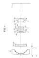
- Fig. 1 is a sectional view showing a lens configuration of a zoom lens system according to Example 1 of a first embodiment in a wide-angle end state.
- the zoom lens system according to Example 1 is composed of, in order from an object, a first lens group G1 having negative refractive power, a second lens group G2 having positive refractive power, a third lens group G3 having negative refractive power, and a fourth lens group G4 having positive refractive power.
- the first lens group G1 is composed of, in order from the object, a negative meniscus lens L11 having a convex surface facing the object, and a cemented lens constructed by a negative meniscus lens L12 having a convex surface facing the object cemented with a positive meniscus lens L13 having a convex surface facing the object.
- the negative meniscus lens L11 is an aspherical lens on which an aspherical surface is formed by forming a resin layer on the image side glass surface.
- the second lens group G2 is composed of, in order from the object, a double convex positive lens L21, and a cemented lens constructed by a double convex positive lens L22 cemented with a double concave negative lens L23.
- the third lens group G3 is composed of a cemented lens constructed by, in order from the object, a positive meniscus lens L31 having a concave surface facing the object cemented with a double concave negative lens L32.
- the fourth lens group G4 is composed of, in order from the object, a positive meniscus lens L41 having a concave surface facing the object, and a cemented lens constructed by a double convex positive lens L42 cemented with a negative meniscus lens L43 having a convex surface facing to the image.
- the zoom lens system according to Example 1 upon zooming from the wide-angle end state to the telephoto end state, the first lens group G1 is moved at first to the image side and then to the object side, and the second lens group G2, the third lens group G3, and the fourth lens group G4 are moved to the object such that a distance between the second lens group G2 and the third lend group G3 increases, and a distance between the third lens group G3 and the fourth lens group G4 decreases.
- the aperture stop S is disposed between the second lens group G2 and the third lens group G3, and is moved together with the third lens group G3 upon zooming from the wide-angle end state to the telephoto end state.
- image plane correction upon occurring an image blur is carried out by shifting the third lens group G3 in a direction perpendicular to the optical axis.
- f denotes a focal length
- FNO denotes an f-number
- W denotes a wide-angle end state
- M denotes an intermediate focal length state
- T denotes a telephoto end state.
- the first column “N” shows the lens surface number counted in order from the object side
- the second column “r” shows a radius of curvature of each lens surface
- the third column “d” shows a distance to the next surface
- Bf denotes a back focal length.
- mm is generally used for the unit of length such as a focal length f, a radius of curvature r, a surface distance d and the like.
- the unit is not necessarily to be limited to "mm", and any other suitable unit can be used.
- the explanation of reference symbols is the same in the other Examples, so that duplicated explanations are omitted.
- a vibration reduction coefficient which is a ratio of a moving amount of an image on the image plane I to that of the vibration reduction lens group perpendicularly to the optical axis upon correcting a camera shake, of K, in order to correct rotational camera shake of an angle of ⁇ , the vibration reduction lens group for correcting the camera shake may be moved by the amount of (f ⁇ tan ⁇ )/K perpendicularly to the optical axis.
- the vibration reduction coefficient K is 1.321, and the focal length is 18.5(mm), so that the moving amount of the third lens group G3 for correcting a rotational camera shake of 0.734 degrees is 0.179(mm).
- the vibration reduction coefficient K is 2.2, and the focal length is 53.4(mm), so that the moving amount of the third lens group G3 for correcting a rotational camera shake of 0.432 degrees is 0.183(mm).
- Figs. 2A and 2B are graphs showing various aberrations of the zoom lens system according to Example 1 of the first embodiment in the wide-angle end state upon focusing on infinity, and coma upon correcting rotational camera shake of 0.734 degrees, respectively.
- Fig. 3 is graphs showing various aberrations of the zoom lens system according to Example 1 of the first embodiment in an intermediate focal length state upon focusing on infinity.
- Figs. 4A and 4B are graphs showing various aberrations of the zoom lens system according to Example 1 of the first embodiment in a telephoto end state upon focusing on infinity, and coma upon correcting rotational camera shake of 0.432 degrees, respectively.
- FNO denotes an f-number
- Y denotes an image height.
- the f-number with respect to the maximum aperture is shown.
- the maximum value of the image height is shown.
- coma coma with respect to each image height is shown.
- astigmatism a solid line indicates a sagittal image plane, and a broken line indicates a meridional image plane.
- the zoom lens system according to Example 1 shows superb optical performance as a result of good corrections to various aberrations from the wide-angle end state to the telephoto end state.
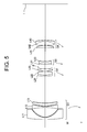
- Fig. 5 is a sectional view showing a lens configuration of a zoom lens system according to Example 2 of the first embodiment in a wide-angle end state.
- the zoom lens system according to Example 2 is composed of, in order from an object, a first lens group G1 having negative refractive power, a second lens group G2 having positive refractive power, a third lens group G3 having negative refractive power, and a fourth lens group G4 having positive refractive power.
- the first lens group G1 is composed of, in order from the object, a negative meniscus lens L11 having a convex surface facing the object, a double concave negative lens L12, and a positive meniscus lens L13 having a convex surface facing the object.
- the negative meniscus lens L11 is an aspherical lens on which an aspherical surface is formed by forming a resin layer on the image side glass surface.
- the second lens group G2 is composed of, in order from the object, a cemented lens constructed by a negative meniscus lens L21 having a convex surface facing the object cemented with a double convex positive lens L22, and a double convex positive lens L23.
- the third lens group G3 is composed of a cemented lens constructed by, in order from the object, a positive meniscus lens L31 having a concave surface facing the object cemented with a double concave negative lens L32.
- the fourth lens group G4 is composed of, in order from the object, a positive meniscus lens L41 having a concave surface facing the object, and a cemented lens constructed by a double convex positive lens L42 cemented with a negative meniscus lens L43 having a convex surface facing an image.
- the zoom lens system according to Example 2 upon zooming from a wide-angle end state to a telephoto end state, the first lens group G1 is moved at first to the image and then to the object, and the second lens group G2, the third lens group G3, and the fourth lens group G4 are moved to the object such that a distance between the second lens group G2 and the third lens group G3 increases, and a distance between the third lens group G3 and the fourth lens group G4 decreases.
- An aperture stop S is disposed between the second lens group G2 and the third lens group G3 and moved together with the third lens group G3 upon zooming from the wide-angle end state to the telephoto end state.
- image plane correction upon occurring an image blur is carried out by shifting the third lens group G3 in a direction perpendicular to the optical axis.
- the vibration reduction coefficient is 1.162, and the focal length is 18.5(mm), so that the moving amount of the third lens group G3 for correcting a rotational camera shake of 0.734 degrees is 0.204(mm).
- the vibration reduction coefficient is 1.914, and the focal length is 53.6(mm), so that the moving amount of the third lens group G3 for correcting a rotational camera shake of 0.432 degrees is 0.211(mm).
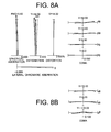
- Figs. 6A and 6B are graphs showing various aberrations of the zoom lens system according to Example 2 of the first embodiment in the wide-angle end state upon focusing on infinity, and coma upon correcting rotational camera shake of 0.734 degrees, respectively.
- Fig. 7 is graphs showing various aberrations of the zoom lens system according to Example 2 of the first embodiment in the intermediate focal length state upon focusing on infinity.
- Figs. 8A and 8B are graphs showing various aberrations of the zoom lens system according to Example 2 of the first embodiment in the telephoto end state upon focusing on infinity, and coma upon correcting rotational camera shake of 0.432 degrees, respectively.
- the zoom lens system according to Example 2 shows superb optical performance as a result of good corrections to various aberrations from the wide-angle end state to the telephoto end state.
- Fig. 9 is a sectional view showing a lens configuration of a zoom lens system according to Example 3 of the first embodiment in a wide-angle end state.
- the zoom lens system according to Example 3 is composed of, in order from an object, a first lens group G1 having negative refractive power, a second lens group G2 having positive refractive power, a third lens group G3 having negative refractive power, and a fourth lens group G4 having positive refractive power.
- the first lens group G1 is composed of, in order from the object, a negative meniscus lens L11 having a convex surface facing the object, a double concave negative lens L12, and a positive meniscus lens L13 having a convex surface facing the object.
- the negative meniscus lens L11 is an aspherical lens on which an aspherical surface is formed by forming a resin layer on the image side glass surface.
- the second lens group G2 is composed of, in order from the object, a cemented lens constructed by a negative meniscus lens L21 having a convex surface facing the object cemented with a double convex positive lens L22, and a double convex positive lens L23.
- the third lens group G3 is composed of a cemented lens constructed by, in order from the object, a double concave negative lens L31 cemented with a positive meniscus lens L32 having a convex surface facing the object.
- the fourth lens group G4 is composed of, in order from the object, a positive meniscus lens L41 having a concave surface facing the object, and a cemented lens constructed by a double convex positive lens L42 cemented with a negative meniscus lens L43 having a convex surface facing an image.
- the zoom lens system according to Example 2 upon zooming from a wide-angle end state to a telephoto end state, the first lens group G1 is moved at first to the image and then to the object, and the second lens group G2, the third lens group G3, and the fourth lens group G4 are moved to the object such that a distance between the second lens group G2 and the third lens group G3 increases, and a distance between the third lens group G3 and the fourth lens group G4 decreases.
- An aperture stop S is disposed between the second lens group G2 and the third lens group G3 and moved together with the third lens group G3 upon zooming from the wide-angle end state to the telephoto end state.
- image plane correction upon occurring an image blur is carried out by shifting the third lens group G3 in a direction perpendicular to the optical axis.
- the vibration reduction coefficient is 1.162, and the focal length is 18.5(mm), so that the moving amount of the third lens group G3 for correcting a rotational camera shake of 0.734 degrees is 0.204(mm).
- the vibration reduction coefficient is 2.037, and the focal length is 53.6(mm), so that the moving amount of the third lens group G3 for correcting a rotational camera shake of 0.432 degrees is 0.198(mm).
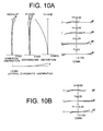
- Figs. 10A and 10B are graphs showing various aberrations of the zoom lens system according to Example 3 of the first embodiment in the wide-angle end state upon focusing on infinity, and coma upon correcting rotational camera shake of 0.734 degrees, respectively.
- Fig. 11 is graphs showing various aberrations of the zoom lens system according to Example 3 of the first embodiment in the intermediate focal length state upon focusing on infinity.
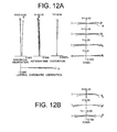
- Figs. 12A and 12B are graphs showing various aberrations of the zoom lens system according to Example 3 of the first embodiment in the telephoto end state upon focusing on infinity, and coma upon correcting rotational camera shake of 0.432 degrees, respectively.
- the zoom lens system according to Example 3 shows superb optical performance as a result of good corrections to various aberrations from the wide-angle end state to the telephoto end state.
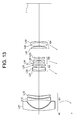
- Fig. 13 is a diagram showing a lens configuration of a zoom lens system according to Example 4 of the first embodiment in a wide-angle end state.
- the zoom lens system according to Example 4 is composed of, in order from an object, a first lens group G1 having negative refractive power, a second lens group G2 having positive refractive power, a third lens group G3 having negative refractive power, and a fourth lens group G4 having positive refractive power.
- the first lens group G1 is composed of, in order from the object, a negative meniscus lens L11 having a convex surface facing the object, a double concave negative lens L12, and a positive meniscus lens L13 having a convex surface facing the object.
- the negative meniscus lens L11 is an aspherical lens on which an aspherical surface is formed by forming a resin layer on the image side glass surface.
- the second lens group G2 is composed of, in order from the object, a cemented lens constructed by a negative meniscus lens L21 having a convex surface facing the object cemented with a double convex positive lens L22, and a double convex positive lens L23.
- the third lens group G3 is composed of, in order from the object, a cemented lens constructed by a positive meniscus lens L31 having a concave surface facing the object cemented with a double concave negative lens L32, and a positive meniscus lens L33 having a concave surface facing an image.
- the fourth lens group G4 is composed of, in order from the object, a positive meniscus lens L41 having a concave surface facing the object, and a cemented lens constructed by a double convex positive lens L42 cemented with a negative meniscus lens L43 having a convex surface facing an image.
- the zoom lens system according to Example 4 upon zooming from a wide-angle end state to a telephoto end state, the first lens group G1 is moved at first to the image and then to the object, and the second lens group G2, the third lens group G3, and the fourth lens group G4 are moved to the object such that a distance between the second lens group G2 and the third lens group G3 increases, and a distance between the third lens group G3 and the fourth lens group G4 decreases.
- An aperture stop S is disposed between the second lens group G2 and the third lens group G3 and moved together with the third lens group G3 upon zooming from the wide-angle end state to the telephoto end state.
- image plane correction upon occurring an image blur is carried out by shifting the third lens group G3 in a direction perpendicular to the optical axis.
- the vibration reduction coefficient is 1.325, and the focal length is 18.5(mm), so that the moving amount of the third lens group G3 for correcting a rotational camera shake of 0.734 degrees is 0.179(mm).
- the vibration reduction coefficient is 2.128, and the focal length is 53.6(mm), so that the moving amount of the third lens group G3 for correcting a rotational camera shake of 0.432 degrees is 0.190(mm).
- Figs. 14A and 14B are graphs showing various aberrations of the zoom lens system according to Example 4 of the first embodiment in the wide-angle end state upon focusing on infinity, and coma upon correcting rotational camera shake of 0.734 degrees, respectively.
- Fig. 15 is graphs showing various aberrations of the zoom lens system according to Example 4 of the first embodiment in the intermediate focal length state upon focusing on infinity.
- Figs. 16A and 16B are graphs showing various aberrations of the zoom lens system according to Example 4 of the first embodiment in the telephoto end state upon focusing on infinity, and coma upon correcting rotational camera shake of 0.432 degrees, respectively.
- the zoom lens system according to Example 4 shows superb optical performance as a result of good corrections to various aberrations from the wide-angle end state to the telephoto end state.
- a zoom lens system having a vibration reduction function according to a second embodiment is explained below.
- a zoom lens system having a vibration reduction function includes, in order from an object, a first lens group having negative refractive power, a second lens group having positive refractive power, a third lens group having negative refractive power, and a fourth lens group having positive refractive power.
- a distance between the second lens group and the third lens group increases, and a distance between the third lens group and the fourth lens group decreases.
- An image blur caused by a camera shake is corrected by moving the third lens group or a portion of the third lens group as a vibration reduction lens group in a direction perpendicular to an optical axis.
- Conditional expression (5) defines the shape of the vibration reduction lens group. With satisfying this, it becomes possible to realize excellent optical performance upon vibration reduction with keeping excellent optical performance with effectively securing a given zoom ratio.
- Conditional expression (6) defines the focal length of the vibration reduction lens group with respect to the focal length of the zoom lens system in the wide-angle end state. With satisfying this, it becomes possible to secure excellent optical performance upon vibration reduction.
- fvr denotes the focal length of the vibration reduction lens group
- f2 denotes a focal length of the second lens group
- Conditional expression (7) defines the focal length of the vibration reduction lens group with respect to the focal length of the second lens group. With satisfying this condition, it becomes possible to realize excellent optical performance upon vibration reduction.
- a zoom lens system having a vibration reduction function includes, in order from an object, a first lens group having negative refractive power, a second lens group having positive refractive power, a third lens group having negative refractive power, and a fourth lens group having positive refractive power.
- a distance between the second lens group and the third lens group increases, and a distance between the third lens group and the fourth lens group decreases.
- An image blur caused by a camera shake is corrected by moving the third lens group or a portion of the third lens group as a vibration reduction lens group in a direction perpendicular to an optical axis.
- Conditional expression (5) defines the shape of the vibration reduction lens group, but has already been explained above, so the duplicated explanation is omitted.
- Conditional expression (7) defines the focal length of the vibration reduction lens group with respect to the focal length of the second lens group. With satisfying this condition, it becomes possible to realize excellent optical performance upon vibration reduction.
- the first lens group upon zooming from the wide-angle end state to the telephoto end state, is preferably moved along a trajectory having convex shape facing the image. With this movement, it becomes possible to accomplish a high zoom ration and to make a moving amount of each lens group small.
- the most image side lens surface has a convex surface facing the image plane.
- the fourth lens group includes, in order from the object, a negative lens, a positive lens, and a positive lens. With this configuration, it becomes possible to excellently correct lateral chromatic aberration and coma with securing the distance between the third lens group as a vibration reduction lens group and the fourth lens group.
- the third lens group preferably has a cemented lens. With this configuration, it becomes possible to excellently keep lateral chromatic aberration upon vibration reduction.
- each of the second lens group, the third lens group, and the fourth lens group includes a cemented lens.
- a zoom lens system having a vibration reduction function it is preferable that upon zooming from the wide-angle end stat to the telephoto end state, the second lens group and the fourth lens group are moved in a body. With this configuration, it becomes possible to excellently correct decentered aberration such as coma and curvature of field generated by the vibration reduction lens group with securing a high zoom ratio.
- an aperture stop is disposed in the vicinity of the third lens group, and moved together with the third lens group upon zooming from the wide-angle end state to the telephoto end state.
- the range in the vicinity of the third lens group includes a space between the second lens group and the third lens group, a space inside of the third lens group, and a space between the third lens group and the fourth lens group.
- the aperture stop is disposed in the vicinity of the second lens group and moved together with the second lens group upon zooming from the wide-angle end state to the telephoto end state.
- the range in the vicinity of the second lens group includes a space between the first lens group and the second lens group, a space inside of the second lens group, and a space between the second lens group and the third lens group.
- a fixed stop is disposed between the third lens group and the fourth lens group.
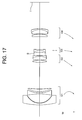
- Fig. 17 is a sectional view showing a lens configuration of a zoom lens system having a vibration reduction function according to Example 5 of the second embodiment in a wide-angle end state.
- the zoom lens system having a vibration reduction function according to Example 5 as shown in Fig. 17 includes, in order from an object, a first lens group G1 having negative refractive power, a second lens group G2 having positive refractive power, an aperture stop S, a third lens group G3 having negative refractive power, and a fourth lens group G4 having positive refractive power.
- the first lens group G1 is composed of, in order from the object, a negative meniscus lens having a convex surface facing the object, a double concave negative lens, and a positive meniscus lens having a convex surface facing the object.
- the most object side negative meniscus lens is an aspherical lens on which an aspherical surface is formed by forming a resin layer on the image plane I side of the glass lens surface.
- the second lens group G2 is composed of, in order from the object, a double convex positive lens, and a cemented lens constructed by a double convex positive lens cemented with a plano-concave negative lens having a plane surface facing the image plane I side.
- the third lens group G3 is composed of a cemented lens constructed by, in order from the object, a positive meniscus lens having a concave surface facing the object cemented with a double concave negative lens.
- the fourth lens group G4 is composed of, in order from the object, a positive meniscus lens having a concave surface facing the object, and a cemented lens constructed by a double convex positive lens cemented with a negative meniscus lens having a convex surface facing to the image plane I side.
- the aperture stop S is disposed between the second lens group G2 and the third lens group G3, and moved together with the third lens group G3 upon zooming from the wide-angle end state to the telephoto end state.
- the first lens group G1 Upon zooming from the wide-angle end state to the telephoto end state, the first lens group G1 is moved along a trajectory having a convex shape facing the image plane I side, the second lens group G2 and the fourth lens group G4 are moved in a body to the object, and the third lens group G3 is moved to the object.
- an image blur on the image plane is corrected by moving the third lens group G3 in a direction perpendicular to the optical axis.
- the vibration reduction coefficient K is 1.02, and the focal length is 18.5(mm), so that the moving amount of the third lens group G3 for correcting a rotational camera shake of 0.734 degrees is 0.232(mm).
- the vibration reduction coefficient K is 1.71, and the focal length is 53.4(mm), so that the moving amount of the third lens group G3 for correcting a rotational camera shake of 0.432 degrees is 0.235(mm).
- Figs. 18A and 18B are graphs showing various aberrations of the zoom lens system according to Example 5 of the first embodiment in the wide-angle end state upon focusing on infinity, and coma upon correcting rotational camera shake, respectively.
- Fig. 19 is graphs showing various aberrations of the zoom lens system according to Example 5 of the first embodiment in the intermediate focal length state upon focusing on infinity.
- Figs. 20A and 20B are graphs showing various aberrations of the zoom lens system according to Example 5 of the first embodiment in the telephoto end state upon focusing on infinity, and coma upon correcting rotational camera shake, respectively.
- the zoom lens system according to Example 5 shows superb optical performance as a result of good corrections to various aberrations from the wide-angle end state to the telephoto end state.
- Fig. 21 is a sectional view showing a lens configuration of a zoom lens system having a vibration reduction function according to Example 6 of the second embodiment in a wide-angle end state.
- the zoom lens system having a vibration reduction function according to Example 6 as shown in Fig. 21 includes, in order from an object, a first lens group G1 having negative refractive power, a second lens group G2 having positive refractive power, an aperture stop S, a third lens group G3 having negative refractive power, and a fourth lens group G4 having positive refractive power.
- the first lens group G1 is composed of, in order from the object, a negative meniscus lens having a convex surface facing the object, a negative meniscus lens having a convex surface facing the object, and a positive meniscus lens having a convex surface facing the object.
- the most object side negative meniscus lens is an aspherical lens on which an aspherical surface is formed by forming a resin layer on the image plane I side of the glass lens surface.
- the second lens group G2 is composed of, in order from the object, a cemented lens constructed by a negative meniscus lens having a convex surface facing the object cemented with a double convex positive lens, and a double convex positive lens.
- the third lens group G3 is composed of, in order from the object, a cemented negative lens constructed by a positive meniscus lens having a concave surface facing the object cemented with a double concave negative lens, and a negative meniscus lens having a convex surface facing the object.
- the fourth lens group G4 is composed of, in order from the object, a positive meniscus lens having a concave surface facing the object, and a cemented lens constructed by a double convex positive lens cemented with a negative meniscus lens having a convex surface facing to the image plane I side.
- the aperture stop S is disposed between the second lens group G2 and the third lens group G3, and moved together with the third lens group G3 upon zooming from the wide-angle end state to the telephoto end state.
- the first lens group G1 Upon zooming from the wide-angle end state to the telephoto end state, the first lens group G1 is moved along a trajectory having a convex shape facing the image plane I side, the second lens group G2 and the fourth lens group G4 are moved in a body to the object, and the third lens group G3 is moved to the object.
- an image blur on the image plane is corrected by moving the cemented negative lens disposed to the object side of the third lens group G3 in a direction perpendicular to the optical axis.
- the vibration reduction coefficient K is 0.807, and the focal length is 18.5(mm), so that the moving amount of the third lens group G3 for correcting a rotational camera shake of 0.734 degrees is 0.294(mm).
- the vibration reduction coefficient K is 1.321, and the focal length is 53.4(mm), so that the moving amount of the third lens group G3 for correcting a rotational camera shake of 0.433 degrees is 0.306(mm).
- Figs. 22A and 22B are graphs showing various aberrations of the zoom lens system according to Example 6 of the first embodiment in the wide-angle end state upon focusing on infinity, and coma upon correcting rotational camera shake, respectively.
- Fig. 23 is graphs showing various aberrations of the zoom lens system according to Example 6 of the first embodiment in the intermediate focal length state upon focusing on infinity.
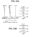
- Figs. 24A and 24B are graphs showing various aberrations of the zoom lens system according to Example 6 of the first embodiment in the telephoto end state upon focusing on infinity, and coma upon correcting rotational camera shake, respectively.
- the zoom lens system according to Example 6 shows superb optical performance as a result of good corrections to various aberrations from the wide-angle end state to the telephoto end state.
- Fig. 25 is a sectional view showing a lens configuration of a zoom lens system having a vibration reduction function according to Example 7 of the second embodiment in a wide-angle end state.
- the zoom lens system having a vibration reduction function according to Example 7 as shown in Fig. 25 includes, in order from an object, a first lens group G1 having negative refractive power, a second lens group G2 including an aperture stop S and having positive refractive power, a third lens group G3 having negative refractive power, and a fourth lens group G4 having positive refractive power.
- the first lens group G1 is composed of, in order from the object, a negative meniscus lens having a convex surface facing the object, a double concave negative lens, and a positive meniscus lens having a convex surface facing the object.
- the most object side negative meniscus lens is an aspherical lens on which an aspherical surface is formed by forming a resin layer on the image plane I side of the glass lens surface.
- the second lens group G2 is composed of, in order from the object, a cemented lens constructed by a negative meniscus lens having a convex surface facing the object cemented with a double convex positive lens, an aperture stop S, and a positive meniscus lens having a convex surface facing the object.
- the third lens group G3 is composed of a cemented lens constructed by, in order from the object, a positive meniscus lens having a concave surface facing the object cemented with a double concave negative lens.
- the fourth lens group G4 is composed of, in order from the object, a positive meniscus lens having a concave surface facing the object, and a cemented lens constructed by a double convex positive lens cemented with a negative meniscus lens having a convex surface facing to the image plane I side.
- the aperture stop S is disposed in the second lens group G2, and moved in a body with the second lens group G2 upon zooming from the wide-angle end state to the telephoto end state.
- the first lens group G1 Upon zooming from the wide-angle end state to the telephoto end state, the first lens group G1 is moved along a trajectory having a convex shape facing the image plane I side, the second lens group G2 and the fourth lens group G4 are moved in a body to the object, and the third lens group G3 is moved to the object.
- an image blur on the image plane is corrected by moving the third lens group G3 in a direction perpendicular to the optical axis.
- the vibration reduction coefficient K is 1.024, and the focal length is 18.5(mm), so that the moving amount of the third lens group G3 for correcting a rotational camera shake of 0.734 degrees is 0.231(mm).
- the vibration reduction coefficient K is 1.674, and the focal length is 53.4(mm), so that the moving amount of the third lens group G3 for correcting a rotational camera shake of 0.432 degrees is 0.241(mm).
- Figs. 26A and 26B are graphs showing various aberrations of the zoom lens system according to Example 7 of the second embodiment in the wide-angle end state upon focusing on infinity, and coma upon correcting rotational camera shake, respectively.
- Fig. 27 is graphs showing various aberrations of the zoom lens system according to Example 7 of the first embodiment in the intermediate focal length state upon focusing on infinity.
- Figs. 28A and 28B are graphs showing various aberrations of the zoom lens system according to Example 7 of the second embodiment in the telephoto end state upon focusing on infinity, and coma upon correcting rotational camera shake, respectively.
- the zoom lens system according to Example 7 shows superb optical performance as a result of good corrections to various aberrations from the wide-angle end state to the telephoto end state.
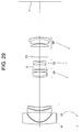
- Fig. 29 is a sectional view showing a lens configuration of a zoom lens system having a vibration reduction function according to Example 8 of the second embodiment in a wide-angle end state.
- the zoom lens system having a vibration reduction function according to Example 8 as shown in Fig. 29 includes, in order from an object, a first lens group G1 having negative refractive power, a second lens group G2 having positive refractive power, an aperture stop S, a third lens group G3 having negative refractive power, a fixed stop FS, and a fourth lens group G4 having positive refractive power.
- the first lens group G1 is composed of, in order from the object, a negative meniscus lens having a convex surface facing the object, a double concave negative lens, and a positive meniscus lens having a convex surface facing the object.
- the most object side negative meniscus lens is an aspherical lens on which an aspherical surface is formed by forming a resin layer on the image plane I side of the glass lens surface.
- the second lens group G2 is composed of, in order from the object, a cemented lens constructed by a negative meniscus lens having a convex surface facing the object cemented with a double convex positive lens, and a positive meniscus lens having a convex surface facing the object.
- the third lens group G3 is composed of a cemented lens constructed by, in order from the object, a positive meniscus lens having a concave surface facing the object cemented with a double concave negative lens.
- the fourth lens group G4 is composed of, in order from the object, a positive meniscus lens having a concave surface facing the object, and a cemented lens constructed by a double convex positive lens cemented with a negative meniscus lens having a convex surface facing to the image plane I side.
- the aperture stop S is disposed between the second lens group G2 and the third lens group G3, and the fixed stop FS is disposed between the third lens group G3 and the fourth lens group G4, and moved together with the third lens group G3 upon zooming from the wide-angle end state to the telephoto end state.
- the first lens group G1 Upon zooming from the wide-angle end state to the telephoto end state, the first lens group G1 is moved along a trajectory having a convex shape facing the image plane I side, the second lens group G2 and the fourth lens group G4 are moved in a body to the object, and the third lens group G3 is moved to the object.
- an image blur on the image plane is corrected by moving the third lens group G3 in a direction perpendicular to the optical axis.
- the vibration reduction coefficient K is 1.186, and the focal length is 18.7(mm), so that the moving amount of the third lens group G3 for correcting a rotational camera shake of 0.731 degrees is 0.202(mm).
- the vibration reduction coefficient K is 1.906, and the focal length is 53.4(mm), so that the moving amount of the third lens group G3 for correcting a rotational camera shake of 0.432 degrees is 0.211(mm).
- Figs. 30A and 30B are graphs showing various aberrations of the zoom lens system according to Example 8 of the second embodiment in the wide-angle end state upon focusing on infinity, and coma upon correcting rotational camera shake, respectively.
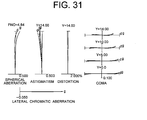
- Fig. 31 is graphs showing various aberrations of the zoom lens system according to Example 8 of the second embodiment in the intermediate focal length state upon focusing on infinity.
- Figs. 32A and 32B are graphs showing various aberrations of the zoom lens system according to Example 8 of the second embodiment in the telephoto end state upon focusing on infinity, and coma upon correcting rotational camera shake, respectively.
- the zoom lens system according to Example 8 shows superb optical performance as a result of good corrections to various aberrations from the wide-angle end state to the telephoto end state.
- Fig. 33 is a sectional view showing a lens configuration of a zoom lens system having a vibration reduction function according to Example 9 of the second embodiment in a wide-angle end state.
- the zoom lens system having a vibration reduction function according to Example 9 as shown in Fig. 33 includes, in order from an object, a first lens group G1 having negative refractive power, a second lens group G2 having positive refractive power, an aperture stop S, a third lens group G3 having negative refractive power, and a fourth lens group G4 having positive refractive power.
- the first lens group G1 is composed of, in order from the object, a negative meniscus lens having a convex surface facing the object, a negative meniscus lens having a convex surface facing the object, and a positive meniscus lens having a convex surface facing the object.
- the most object side negative meniscus lens is an aspherical lens on which an aspherical surface is formed by forming a resin layer on the image plane I side of the glass lens surface.
- the second lens group G2 is composed of, in order from the object, a cemented lens constructed by a negative meniscus lens having a convex surface facing the object cemented with a double convex positive lens, and a double convex positive lens.
- the third lens group G3 is composed of, in order from the object, a cemented negative lens constructed by a positive meniscus lens having a concave surface facing the object cemented with a double concave negative lens, a positive meniscus lens having a concave surface facing the object, and a negative meniscus lens having a convex surface facing the object.
- the fourth lens group G4 is composed of, in order from the object, a positive meniscus lens having a concave surface facing the object, and a cemented lens constructed by a double convex positive lens cemented with a negative meniscus lens having a convex surface facing to the image plane I side.
- the aperture stop S is disposed between the second lens group G2 and the third lens group G3, and moved together with the third lens group G3 upon zooming from the wide-angle end state to the telephoto end state.
- the first lens group G1 Upon zooming from the wide-angle end state to the telephoto end state, the first lens group G1 is moved along a trajectory having a convex shape facing the image plane I side, the second lens group G2 and the fourth lens group G4 are moved in a body to the object, and the third lens group G3 is moved to the object.
- an image blur on the image plane is corrected by moving the cemented negative lens and the positive meniscus lens having a convex surface facing the object in the third lens group G3 in a direction perpendicular to the optical axis.
- the vibration reduction coefficient K is 1.086, and the focal length is 18.7(mm), so that the moving amount of the third lens group G3 for correcting a rotational camera shake of 0.731 degrees is 0.218(mm).
- the vibration reduction coefficient K is 1.792, and the focal length is 53.4(mm), so that the moving amount of the third lens group G3 for correcting a rotational camera shake of 0.432 degrees is 0.225(mm).
- Figs. 34A and 34B are graphs showing various aberrations of the zoom lens system according to Example 9 of the second embodiment in the wide-angle end state upon focusing on infinity, and coma upon correcting rotational camera shake, respectively.
- Fig. 35 is graphs showing various aberrations of the zoom lens system according to Example 9 of the second embodiment in the intermediate focal length state upon focusing on infinity.
- Figs. 36A and 36B are graphs showing various aberrations of the zoom lens system according to Example 9 of the second embodiment in the telephoto end state upon focusing on infinity, and coma upon correcting rotational camera shake, respectively.
- the zoom lens system according to Example 9 shows superb optical performance as a result of good corrections to various aberrations from the wide-angle end state to the telephoto end state.
- a zoom lens system having a vibration reduction function according to a third embodiment of the present application is explained below.
- a zoom lens system having a vibration reduction function includes, in order from an object, a first lens group having negative refractive power, a second lens group having positive refractive power, a third lens group having negative refractive power, and a fourth lens group having positive refractive power.
- each lens group moves such that a distance between the second lens group and the third lens group varies, and a distance between the third lens group and the fourth lens group decreases.
- At least one portion of the third lens group is moved as a vibration reduction lens group in a direction perpendicular to the optical axis upon carrying out image plane correction upon a camera shake.
- the vibration reduction lens group includes at least one aspherical surface.
- conditional expressions (1) and (2) are satisfied: 1.20 ⁇ f ⁇ 2 / fw ⁇ 2.50 - 2.10 ⁇ f ⁇ 3 / fw ⁇ - 0.80
- f2 denotes a focal length of the second lens group
- f3 denotes a focal length of the third lens group
- fw denotes a focal length of the zoom lens system in the wide-angle end state.
- Conditional expression (1) defines refractive power of the second lens group. However, it has been explained above, so that duplicated explanation is omitted.
- Conditional expression (2) defines refractive power of the third lens group. However, it has been explained above, so that duplicated explanation is omitted.
- the at least one aspherical surface in the third lens group has a shape that positive refractive power becomes stronger or negative refractive power becomes weaker from the optical axis to the periphery in comparison with a spherical surface having a paraxial radius of curvature.
- Conditional expressions (8), (9) and (10) define the aspherical shape for suppressing deterioration in optical performance upon moving the third lens group as a vibration reduction lens group in a direction perpendicular to the optical axis.
- conditional expressions (8) and (9) When respective values are equal to or fall below the lower limits of conditional expressions (8) and (9), effect of the aspherical surface cannot shows, and the number of lenses for correcting various aberrations increases, so that it is undesirable. Otherwise, coma becomes worse, so that it is undesirable.
- the values are equal to or exceed the upper limits of conditional expressions (8) and (9), correction of aberrations such as spherical aberration become excessive, and optical performance upon moving the vibration reduction lens group becomes worse.
- the aspherical surface has a shape that positive refractive power becomes stronger or negative refractive power becomes weaker from the optical axis to the periphery than a spherical surface having the same paraxial radius of curvature, it becomes possible to effectively correct on-axis and off-axis aberrations upon moving the vibration reduction lens.
- the value is equal to or exceeds the upper limit of conditional expression (10)
- spherical aberration and high order coma are generated in the vibration reduction lens group upon moving the vibration reduction lens group, so that optical performance upon vibration reduction becomes worse.
- the third lens group preferably has a cemented lens. With this configuration, it becomes possible to sufficiently suppress lateral chromatic aberration upon vibration reduction.
- the first lens group includes at least one aspherical surface, and is composed of three lenses or less. With this configuration, it becomes possible to reduce total lens length, and to excellently correct curvature of field.
- the most object side lens in the first lens group has negative refractive power and an aspherical surface formed on the image side surface.
- the fourth lens group is composed of three lenses or less, and has at least one aspherical surface. With this configuration, it becomes possible to shorten the lens length, and to excellently correct coma.
- each of the second lens group through the fourth lens group has at least one cemented lens.
- the most image side lens surface has a convex shape facing the image plane.
- Fig. 37 is a sectional view showing a lens configuration of a zoom lens system having a vibration reduction function according to Example 10 of a third embodiment in a wide-angle end state.
- the zoom lens system having a vibration reduction function according to Example 10 is composed of as shown in Fig. 37 , in order from an object, a first lens group G1 having negative refractive power, a second lens group G2 having positive refractive power, an aperture stop S, a third lens group G3 having negative refractive power, and a fourth lens group G4 having positive refractive power.
- the first lens group G1 is composed of, in order from the object, a negative meniscus lens having a convex surface facing the object, a double concave negative lens, and a positive meniscus lens having a convex surface facing the object.
- the most object side negative meniscus lens is an aspherical lens on which an aspherical surface is formed by forming a resin layer on the image plane I side of the glass lens surface.
- the second lens group G2 is composed of, in order from the object, a cemented lens constructed by a negative meniscus lens having a convex surface facing the object cemented with a double convex positive lens, and a positive meniscus lens having a convex surface facing the object.
- the third lens group G3 is composed of a cemented lens constructed by, in order from the object, a positive meniscus lens having a concave surface facing the object cemented with a double concave negative lens.
- the fourth lens group G4 is composed of, in order from the object, a double convex positive lens, and a cemented lens constructed by a double convex positive lens cemented with a negative meniscus lens having a convex surface facing the image plane I side.
- the aperture stop S is disposed between the second lens group G2 and the third lens group G3, and is moved together with the third lens group G3 upon zooming from the wide-angle end state to the telephoto end state.
- the first lens group G1 Upon zooming from the wide-angle end state to the telephoto end state, the first lens group G1 is moved along a trajectory having a convex shape facing the image plane I, and the second lens group G2, the third lens group G3, and the fourth lens group G4 are moved to the object side.
- an image blur on the image plane is corrected by moving the third lens group G3 group in a direction perpendicular to the optical axis.
- the vibration reduction coefficient K is 1.155, and the focal length is 18.7(mm), so that the moving amount of the third lens group G3 for correcting a rotational camera shake of 0.731 degrees is 0.207(mm).
- the vibration reduction coefficient K is 1.845, and the focal length is 53.3(mm), so that the moving amount of the third lens group G3 for correcting a rotational camera shake of 0.433 degrees is 0.218(mm).
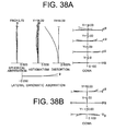
- Figs. 38A and 38B are graphs showing various aberrations of the zoom lens system according to Example 10 of the third embodiment in the wide-angle end state upon focusing on infinity, and coma upon correcting rotational camera shake, respectively.
- Fig. 39 is graphs showing various aberrations of the zoom lens system according to Example 10 of the third embodiment in the intermediate focal length state upon focusing on infinity.
- Figs. 40A and 40B are graphs showing various aberrations of the zoom lens system according to Example 10 of the third embodiment in the telephoto end state upon focusing on infinity, and coma upon correcting rotational camera shake, respectively.
- the zoom lens system having a vibration reduction function according to Example 10 shows superb optical performance as a result of good corrections to various aberrations from the wide-angle end state to the telephoto end state.
- Fig. 41 is a sectional view showing a lens configuration of a zoom lens system having a vibration reduction function according to Example 11 of the third embodiment in a wide-angle end state.
- the zoom lens system having a vibration reduction function according to Example 11 is composed of as shown in Fig. 41 , in order from an object, a first lens group G1 having negative refractive power, a second lens group G2 having positive refractive power, an aperture stop S, a third lens group G3 having negative refractive power, and a fourth lens group G4 having positive refractive power.
- the first lens group G1 is composed of, in order from the object, a negative meniscus lens having a convex surface facing the object, a double concave negative lens, and a positive meniscus lens having a convex surface facing the object.
- the most object side negative meniscus lens is an aspherical lens on which an aspherical surface is formed by forming a resin layer on the image plane I side of the glass lens surface.
- the second lens group G2 is composed of, in order from the object, a double convex positive lens, and a cemented lens constructed by a double convex positive lens cemented with a double concave negative lens.
- the third lens group G3 is composed of a cemented lens constructed by, in order from the object, a positive meniscus lens having a concave surface facing the object cemented with a double concave negative lens.
- the fourth lens group G4 is composed of a cemented lens constructed by, in order from the object, a double convex positive lens cemented with a negative meniscus lens having a convex surface facing the image plane I side.
- the cemented lens is an aspherical lens on which an aspherical surface is formed by forming a resin layer on the object side glass lens surface.
- the aperture stop S is disposed between the second lens group G2 and the third lens group G3, and is moved together with the third lens group G3 upon zooming from the wide-angle end state to the telephoto end state.
- the first lens group G1 Upon zooming from the wide-angle end state to the telephoto end state, the first lens group G1 is moved along a trajectory having a convex shape facing the image plane I, and the second lens group G2, the third lens group G3, and the fourth lens group G4 are moved to the object side.
- the vibration reduction coefficient K is 1.024, and the focal length is 19.0(mm), so that the moving amount of the third lens group G3 for correcting a rotational camera shake of 0.725 degrees is 0.234(mm).
- the vibration reduction coefficient K is 1.785, and the focal length is 54.0(mm), so that the moving amount of the third lens group G3 for correcting a rotational camera shake of 0.430 degrees is 0.227(mm).
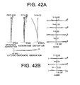
- Figs. 42A and 42B are graphs showing various aberrations of the zoom lens system according to Example 11 of the third embodiment in the wide-angle end state upon focusing on infinity, and coma upon correcting rotational camera shake, respectively.
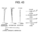
- Fig. 43 is graphs showing various aberrations of the zoom lens system according to Example 11 of the third embodiment in the intermediate focal length state upon focusing on infinity.
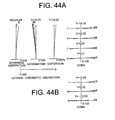
- Figs. 44A and 44B are graphs showing various aberrations of the zoom lens system according to Example 11 of the third embodiment in the telephoto end state upon focusing on infinity, and coma upon correcting rotational camera shake, respectively.
- the zoom lens system having a vibration reduction function according to Example 11 shows superb optical performance as a result of good corrections to various aberrations from the wide-angle end state to the telephoto end state.
- Fig. 45 is a sectional view showing a lens configuration of a zoom lens system having a vibration reduction function according to Example 12 of the third embodiment in a wide-angle end state.
- the zoom lens system having a vibration reduction function according to Example 12 is composed of as shown in Fig. 45 , in order from an object, a first lens group G1 having negative refractive power, a second lens group G2 having positive refractive power, an aperture stop S, a third lens group G3 having negative refractive power, and a fourth lens group G4 having positive refractive power.
- the first lens group G1 is composed of, in order from the object, a negative meniscus lens having a convex surface facing the object, a double concave negative lens, and a positive meniscus lens having a convex surface facing the object.
- the most object side negative meniscus lens is an aspherical lens on which an aspherical surface is formed by forming a resin layer on the image plane I side of the glass lens surface.
- the second lens group G2 is composed of, in order from the object, a cemented lens constructed by a negative meniscus lens having a convex surface facing the object cemented with a double convex positive lens, and a positive meniscus lens having a convex surface facing the object.
- the third lens group G3 is composed of a cemented lens constructed by, in order from the object, a positive meniscus lens having a concave surface facing the object cemented with a double concave negative lens.
- the fourth lens group G4 is composed of, in order from the object, a double convex positive lens, and a cemented lens constructed by a double convex positive lens cemented with a negative meniscus lens having a convex surface facing the image plane I side.
- the aperture stop S is disposed between the second lens group G2 and the third lens group G3, and is moved together with the third lens group G3 upon zooming from the wide-angle end state to the telephoto end state.
- the first lens group G1 Upon zooming from the wide-angle end state to the telephoto end state, the first lens group G1 is moved along a trajectory having a convex shape facing the image plane I, and the second lens group G2, the third lens group G3, and the fourth lens group G4 are moved to the object side.
- an image blur on the image plane is corrected by moving the third lens group G3 group in a direction perpendicular to the optical axis.
- the vibration reduction coefficient K is 1.162, and the focal length is 18.5(mm), so that the moving amount of the third lens group G3 for correcting a rotational camera shake of 0.734 degrees is 0.204(mm).
- the vibration reduction coefficient K is 2.037, and the focal length is 53.5(mm), so that the moving amount of the third lens group G3 for correcting a rotational camera shake of 0.432 degrees is 0.198(mm).
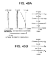
- Figs. 46A and 46B are graphs showing various aberrations of the zoom lens system according to Example 12 of the third embodiment in the wide-angle end state upon focusing on infinity, and coma upon correcting rotational camera shake, respectively.
- Fig. 47 is graphs showing various aberrations of the zoom lens system according to Example 12 of the third embodiment in the intermediate focal length state upon focusing on infinity.
- Figs. 48A and 48B are graphs showing various aberrations of the zoom lens system according to Example 12 of the third embodiment in the telephoto end state upon focusing on infinity, and coma upon correcting rotational camera shake, respectively.
- the zoom lens system having a vibration reduction function according to Example 12 shows superb optical performance as a result of good corrections to various aberrations from the wide-angle end state to the telephoto end state.
- each embodiment makes it possible to provide a zoom lens system having a vibration reduction function with excellent optical performance capable of correcting an image blur on the image plane cased by a camera shake with keeping a high zoom ratio.
- the lens configuration according to the present embodiment is not limited to this, and is applicable to other lens configurations such as a five-lens-group configuration.
- a portion of a lens group, a single lens group, or a plurality of lens groups may be moved along the optical axis.
- the focusing lens group(s) may be used for auto focus, and suitable for being driven by a motor such as an ultrasonic motor. It is preferable that the first lens group G1 or a portion thereof is used for the focusing lens group.
- the third lens group G3 or a portion thereof is moved as a vibration reduction lens group in a direction perpendicular to the optical axis
- another lens group or a portion thereof in particular, the second lens group G2 or the fourth lens group G4 may be made as a vibration reduction lens group
- any lens surface composing the high zoom ratio zoom lens system according to the present application may be an aspherical surface.
- the aspherical surface may be fabricated by a fine grinding process, a glass molding process that a glass material is formed into an aspherical shape by a mold, or a compound type process that a resin material is formed into an aspherical shape on a glass surface.
- An antireflection coating having high transmittance over a broad wavelength range may be applied to each lens surface of the zoom lens system having a vibration reduction function according to the present application to reduce flare or ghost images, so that high optical performance with a high contrast can be attained.
- an imaging apparatus (a single-lens reflex camera) equipped with the zoom lens system having a vibration reduction function according to present application is explained.
- Fig. 49 is a diagram showing an imaging apparatus (camera) equipped with the zoom lens system with a vibration reduction function according to Example 1 of the first embodiment.
- Fig. 49 light coming out from an object (not shown) is converged by a zoom lens system 11 with a vibration reduction function, reflected by a quick return mirror 12, and focused on a focusing screen 13.
- the object image focused on the focusing screen 13 is reflected a plurality of times by a pentagonal roof prism 14, and observed by a photographer as an erected image through an eyepiece 15.
- the photographer presses the release button all the way down.
- the quick return mirror 12 is flipped up, the light from the object is detected by an imaging device 16, and a photographed image is captured and stored in a memory (not shown).
- a tilt of the camera 10 is detected by a sensor 17 such as an angular sensor stored in the camera 10, and transmitted to a CPU 18. Then, an amount of a rotational camera shake is detected by the CPU 18, a lens driver 19 for driving a vibration reduction lens group in a direction perpendicular to the optical axis is driven, and an image blur on the imaging device 16 upon generating a camera shake is corrected. In this manner, the imaging apparatus 10 using the zoom lens system 11 with a vibration reduction function is constructed.
Landscapes
- Physics & Mathematics (AREA)
- General Physics & Mathematics (AREA)
- Optics & Photonics (AREA)
- Nonlinear Science (AREA)
- Lenses (AREA)
Applications Claiming Priority (6)
| Application Number | Priority Date | Filing Date | Title |
|---|---|---|---|
| JP2006199860 | 2006-07-21 | ||
| JP2006341590 | 2006-12-19 | ||
| JP2006347841A JP5082431B2 (ja) | 2006-12-25 | 2006-12-25 | 防振機能を有する変倍光学系、撮像装置、変倍光学系の変倍方法 |
| JP2007177540A JP5358902B2 (ja) | 2006-12-19 | 2007-07-05 | 防振機能を有する変倍光学系、撮像装置 |
| JP2007177530A JP5130806B2 (ja) | 2006-07-21 | 2007-07-05 | 変倍光学系、撮像装置、変倍光学系の変倍方法 |
| PCT/JP2007/064300 WO2008010563A1 (fr) | 2006-07-21 | 2007-07-12 | Système optique à puissance variable, dispositif d'imagerie, procédé d'agrandissement variable d'un système optique à puissance variable |
Publications (2)
| Publication Number | Publication Date |
|---|---|
| EP2045639A1 true EP2045639A1 (fr) | 2009-04-08 |
| EP2045639A4 EP2045639A4 (fr) | 2012-06-13 |
Family
ID=40404371
Family Applications (1)
| Application Number | Title | Priority Date | Filing Date |
|---|---|---|---|
| EP07791042A Withdrawn EP2045639A4 (fr) | 2006-07-21 | 2007-07-12 | Système optique à puissance variable, dispositif d'imagerie, procédé d'agrandissement variable d'un système optique à puissance variable |
Country Status (4)
| Country | Link |
|---|---|
| US (4) | US20090231708A1 (fr) |
| EP (1) | EP2045639A4 (fr) |
| CN (2) | CN102608736A (fr) |
| WO (1) | WO2008010563A1 (fr) |
Cited By (1)
| Publication number | Priority date | Publication date | Assignee | Title |
|---|---|---|---|---|
| US11231567B2 (en) | 2015-01-30 | 2022-01-25 | Nikon Corporation | Variable magnification optical system, optical apparatus, and method for manufacturing variable magnification optical system |
Families Citing this family (31)
| Publication number | Priority date | Publication date | Assignee | Title |
|---|---|---|---|---|
| CN102608736A (zh) | 2006-07-21 | 2012-07-25 | 株式会社尼康 | 变焦透镜系统、成像设备和变焦透镜系统的变焦方法 |
| US8270095B2 (en) * | 2006-12-20 | 2012-09-18 | Konica Minolta Opto, Inc. | Variable-power optical system, image pickup device, and digital apparatus |
| JP5458477B2 (ja) | 2007-06-29 | 2014-04-02 | 株式会社ニコン | 変倍光学系、光学装置、変倍光学系の変倍方法 |
| JP5407119B2 (ja) | 2007-06-29 | 2014-02-05 | 株式会社ニコン | 変倍光学系、光学装置、変倍光学系の変倍方法 |
| JP5018757B2 (ja) * | 2008-12-09 | 2012-09-05 | 富士通株式会社 | パラレル−シリアル変換器及びデータ受信システム |
| JP5544731B2 (ja) * | 2009-03-17 | 2014-07-09 | 株式会社ニコン | 撮影レンズ、及び、この撮影レンズを備えた光学機器 |
| JP5493942B2 (ja) | 2009-12-15 | 2014-05-14 | ソニー株式会社 | 撮像装置と撮像方法 |
| CN103370647B (zh) * | 2010-12-17 | 2018-02-02 | 株式会社尼康 | 光学系统、成像装置及用于制造光学系统的方法 |
| WO2012086154A1 (fr) * | 2010-12-22 | 2012-06-28 | パナソニック株式会社 | Système d'objectif à focale variable, dispositif à objectif interchangeable, et système d'appareil photographique |
| JP5676505B2 (ja) * | 2011-04-07 | 2015-02-25 | パナソニックIpマネジメント株式会社 | ズームレンズ系、撮像装置及びカメラ |
| JP2013015778A (ja) * | 2011-07-06 | 2013-01-24 | Konica Minolta Advanced Layers Inc | ズームレンズ,撮像光学装置及びデジタル機器 |
| CN102880867B (zh) * | 2011-09-06 | 2015-10-28 | 友尼嗯可缪尼体有限公司 | 光学指纹采集装置 |
| CN103176263B (zh) * | 2013-02-20 | 2015-10-28 | 福建福光股份有限公司 | 三百万像素日夜两用P-iris镜头 |
| JP5781244B2 (ja) | 2013-06-21 | 2015-09-16 | オリンパス株式会社 | ズームレンズ及びそれを有する撮像装置 |
| JP2015004880A (ja) * | 2013-06-21 | 2015-01-08 | オリンパスイメージング株式会社 | ズームレンズ及びそれを有する撮像装置 |
| CN103389563B (zh) * | 2013-08-15 | 2015-06-17 | 福建福光数码科技有限公司 | Cs接口塑料结构超清摄像镜头 |
| JP2015121768A (ja) | 2013-11-21 | 2015-07-02 | 株式会社ニコン | ズームレンズ、光学機器及びズームレンズの製造方法 |
| US10495856B2 (en) * | 2014-10-27 | 2019-12-03 | Alex Ning | Wide-angle lenses with low distortion |
| JP2016126282A (ja) * | 2015-01-08 | 2016-07-11 | 株式会社タムロン | 広角ズームレンズ及び撮像装置 |
| JP2018010219A (ja) | 2016-07-15 | 2018-01-18 | 株式会社ニコン | 変倍光学系、光学機器及び変倍光学系の製造方法 |
| JP6798296B2 (ja) * | 2016-12-09 | 2020-12-09 | 株式会社リコー | 変倍光学系 |
| CN109975949B (zh) * | 2017-12-27 | 2021-02-19 | 青岛海信激光显示股份有限公司 | 一种投影镜头及投影系统 |
| JP6820878B2 (ja) | 2018-03-29 | 2021-01-27 | 富士フイルム株式会社 | ズームレンズ及び撮像装置 |
| CN109194877B (zh) * | 2018-10-31 | 2021-03-02 | Oppo广东移动通信有限公司 | 图像补偿方法和装置、计算机可读存储介质和电子设备 |
| CN109298584B (zh) * | 2018-12-04 | 2021-04-02 | 深圳小象光显有限公司 | 投影镜头及投影机 |
| CN113348397B (zh) * | 2019-01-28 | 2022-09-20 | 株式会社尼康 | 变倍光学系统以及光学设备 |
| WO2021039814A1 (fr) | 2019-08-30 | 2021-03-04 | 株式会社ニコン | Système optique, dispositif optique et procédé de fabrication d'un système optique |
| CN114341696B (zh) | 2019-08-30 | 2023-12-29 | 株式会社尼康 | 光学系统以及光学设备 |
| WO2021068098A1 (fr) * | 2019-10-08 | 2021-04-15 | Huawei Technologies Co., Ltd. | Appareil optique, appareil d'imagerie et équipement mobile |
| TWI768422B (zh) * | 2020-07-31 | 2022-06-21 | 大立光電股份有限公司 | 影像鏡片組、變焦取像裝置及電子裝置 |
| TW202603430A (zh) * | 2024-03-29 | 2026-01-16 | 韓商Lg伊諾特股份有限公司 | 光學系統及相機模組 |
Family Cites Families (61)
| Publication number | Priority date | Publication date | Assignee | Title |
|---|---|---|---|---|
| JPS5895315A (ja) * | 1981-11-30 | 1983-06-06 | Minolta Camera Co Ltd | 広角域を含む高変倍率ズ−ムレンズ系 |
| JPS63281113A (ja) | 1987-05-13 | 1988-11-17 | Matsushita Electric Ind Co Ltd | ズ−ムレンズ |
| JP2629904B2 (ja) | 1988-11-18 | 1997-07-16 | キヤノン株式会社 | リヤーフォーカス式のズームレンズ |
| US5000550A (en) * | 1989-01-30 | 1991-03-19 | Canon Kabushiki Kaisha | Wide-angle type zoom lens having inner-focus lens |
| JPH04235515A (ja) | 1991-01-11 | 1992-08-24 | Nikon Corp | 超広角ズームレンズ |
| JPH04235514A (ja) | 1991-01-11 | 1992-08-24 | Nikon Corp | 超広角ズームレンズ |
| US5329401A (en) | 1991-01-11 | 1994-07-12 | Nikon Corporation | Super wide angle zoom lens |
| JP3042107B2 (ja) | 1991-11-13 | 2000-05-15 | ミノルタ株式会社 | ズームレンズ |
| JP3018742B2 (ja) | 1992-05-11 | 2000-03-13 | キヤノン株式会社 | ズームレンズ |
| US5517361A (en) | 1992-12-11 | 1996-05-14 | Nikon Corporation | Zoom lens system |
| JPH06180423A (ja) | 1992-12-15 | 1994-06-28 | Nikon Corp | ズームレンズ系 |
| JPH07152002A (ja) | 1993-11-29 | 1995-06-16 | Nikon Corp | 防振機能を備えたズームレンズ |
| US5585970A (en) | 1994-04-19 | 1996-12-17 | Nikon Corporation | Zoom lens with high zoom ratio |
| JPH07287168A (ja) | 1994-04-19 | 1995-10-31 | Nikon Corp | 高変倍率ズームレンズ |
| JPH08106048A (ja) | 1994-10-06 | 1996-04-23 | Canon Inc | ズームレンズ |
| US5774267A (en) * | 1995-10-20 | 1998-06-30 | Nikon Corporation | Zoom lens |
| JPH09113808A (ja) * | 1995-10-20 | 1997-05-02 | Nikon Corp | ズームレンズ |
| US5999329A (en) * | 1995-12-26 | 1999-12-07 | Nikon Corporation | Variable focal length optical system |
| JPH09211323A (ja) | 1996-02-07 | 1997-08-15 | Konica Corp | 有限距離用ズームレンズ |
| JP3926411B2 (ja) | 1996-07-09 | 2007-06-06 | リコー光学株式会社 | カラープロジェクタ用ズームレンズ |
| JPH1039210A (ja) * | 1996-07-24 | 1998-02-13 | Nikon Corp | ズームレンズ |
| JP3362613B2 (ja) | 1996-10-30 | 2003-01-07 | ミノルタ株式会社 | ズームレンズ |
| US5914820A (en) | 1996-10-30 | 1999-06-22 | Minolta Co., Ltd. | Zoom lens system |
| US5805351A (en) | 1997-03-13 | 1998-09-08 | Nikon Corporation | High speed wide angle zoom lens system |
| US5963377A (en) * | 1997-10-02 | 1999-10-05 | Minolta Co., Ltd. | Taking optical system for video shooting |
| JPH11174329A (ja) * | 1997-12-15 | 1999-07-02 | Canon Inc | 防振機能を有した変倍光学系 |
| JP2000241704A (ja) * | 1999-02-18 | 2000-09-08 | Asahi Optical Co Ltd | ズームレンズ系 |
| JP4392901B2 (ja) * | 1999-05-26 | 2010-01-06 | キヤノン株式会社 | ズームレンズ |
| JP2001116992A (ja) | 1999-10-18 | 2001-04-27 | Canon Inc | ズームレンズ |
| JP4378008B2 (ja) * | 1999-12-22 | 2009-12-02 | キヤノン株式会社 | 防振ズームレンズ |
| JP4672827B2 (ja) | 2000-01-28 | 2011-04-20 | 株式会社栃木ニコン | ズームレンズ及び該ズームレンズを備える投射型表示装置 |
| JP2002244044A (ja) * | 2001-02-19 | 2002-08-28 | Canon Inc | ズームレンズ及びそれを用いた光学機器 |
| JP3503631B2 (ja) * | 2001-04-27 | 2004-03-08 | セイコーエプソン株式会社 | 投映用ズームレンズ及びこれを備えたプロジェクター |
| US6721105B2 (en) * | 2001-12-12 | 2004-04-13 | Nikon Corporation | Zoom lens system |
| JP2003215455A (ja) | 2002-01-25 | 2003-07-30 | Canon Inc | ズームレンズ及びそれを有する投影装置 |
| JP2004061910A (ja) | 2002-07-30 | 2004-02-26 | Canon Inc | 防振機能を備えたズームレンズ |
| JP4360086B2 (ja) | 2002-12-27 | 2009-11-11 | 株式会社ニコン | ズームレンズ |
| JP4366091B2 (ja) | 2003-02-04 | 2009-11-18 | キヤノン株式会社 | ズームレンズ |
| JP4206769B2 (ja) * | 2003-02-10 | 2009-01-14 | セイコーエプソン株式会社 | 投映用ズームレンズ及びこれを備えたプロジェクター |
| JP4325209B2 (ja) | 2003-02-13 | 2009-09-02 | 株式会社ニコン | 可変焦点距離レンズ系 |
| JP3786103B2 (ja) * | 2003-05-02 | 2006-06-14 | セイコーエプソン株式会社 | 半導体装置、電子デバイス、電子機器および半導体装置の製造方法 |
| US7106520B2 (en) | 2003-05-06 | 2006-09-12 | Pentax Corporation | Wide-angle zoom lens system |
| JP4324508B2 (ja) | 2003-05-06 | 2009-09-02 | Hoya株式会社 | 広角ズームレンズ系 |
| JP4720117B2 (ja) | 2003-07-17 | 2011-07-13 | 株式会社ニコン | ズームレンズ |
| US6989939B2 (en) | 2003-08-11 | 2006-01-24 | Canon Kabushiki Kaisha | Variable-power optical system, projection optical system, and image projection apparatus using the systems |
| JP2005106948A (ja) | 2003-09-29 | 2005-04-21 | Canon Inc | 投射光学系及び画像投射装置 |
| JP4289958B2 (ja) * | 2003-09-19 | 2009-07-01 | キヤノン株式会社 | ズームレンズ及びそれを有する撮像装置 |
| JP4507543B2 (ja) | 2003-09-29 | 2010-07-21 | 株式会社ニコン | ズームレンズ |
| JP4642386B2 (ja) | 2004-06-09 | 2011-03-02 | キヤノン株式会社 | ズームレンズ及びそれを有する撮像装置 |
| JP4819414B2 (ja) | 2004-06-25 | 2011-11-24 | キヤノン株式会社 | ズームレンズ及びそれを有する撮像装置 |
| US7075730B2 (en) | 2004-06-25 | 2006-07-11 | Canon Kabushiki Kaisha | Zoom lens system and image pickup apparatus including the same |
| JP2006113573A (ja) * | 2004-09-17 | 2006-04-27 | Pentax Corp | ズームレンズ系 |
| US7307794B2 (en) * | 2004-09-17 | 2007-12-11 | Pentax Corporation | Zoom lens system |
| JP4681842B2 (ja) | 2004-09-30 | 2011-05-11 | キヤノン株式会社 | ズームレンズ及びそれを有する撮像装置 |
| JP4738823B2 (ja) | 2005-01-31 | 2011-08-03 | キヤノン株式会社 | ズームレンズ及びそれを有する撮像装置 |
| JP4820587B2 (ja) * | 2005-06-29 | 2011-11-24 | Hoya株式会社 | 広角ズームレンズ系 |
| JP4834360B2 (ja) | 2005-09-12 | 2011-12-14 | キヤノン株式会社 | ズームレンズ及びそれを有する撮像装置 |
| JP4876510B2 (ja) * | 2005-09-28 | 2012-02-15 | 株式会社ニコン | ズームレンズ |
| US7333273B2 (en) * | 2006-03-24 | 2008-02-19 | Nikon Corporation | Zoom lens system, imaging apparatus and method for varying focal length |
| CN102608736A (zh) | 2006-07-21 | 2012-07-25 | 株式会社尼康 | 变焦透镜系统、成像设备和变焦透镜系统的变焦方法 |
| JP5407119B2 (ja) * | 2007-06-29 | 2014-02-05 | 株式会社ニコン | 変倍光学系、光学装置、変倍光学系の変倍方法 |
-
2007
- 2007-07-12 CN CN2012100553814A patent/CN102608736A/zh active Pending
- 2007-07-12 US US12/303,305 patent/US20090231708A1/en not_active Abandoned
- 2007-07-12 EP EP07791042A patent/EP2045639A4/fr not_active Withdrawn
- 2007-07-12 WO PCT/JP2007/064300 patent/WO2008010563A1/fr not_active Ceased
- 2007-07-12 CN CN200780027520XA patent/CN101490594B/zh not_active Expired - Fee Related
-
2011
- 2011-04-20 US US13/090,936 patent/US20110194191A1/en not_active Abandoned
-
2012
- 2012-07-10 US US13/545,651 patent/US20120275032A1/en not_active Abandoned
-
2013
- 2013-11-27 US US14/092,748 patent/US10437026B2/en not_active Expired - Fee Related
Cited By (1)
| Publication number | Priority date | Publication date | Assignee | Title |
|---|---|---|---|---|
| US11231567B2 (en) | 2015-01-30 | 2022-01-25 | Nikon Corporation | Variable magnification optical system, optical apparatus, and method for manufacturing variable magnification optical system |
Also Published As
| Publication number | Publication date |
|---|---|
| US20110194191A1 (en) | 2011-08-11 |
| CN102608736A (zh) | 2012-07-25 |
| US20090231708A1 (en) | 2009-09-17 |
| US20140085732A1 (en) | 2014-03-27 |
| CN101490594B (zh) | 2012-05-16 |
| CN101490594A (zh) | 2009-07-22 |
| US20120275032A1 (en) | 2012-11-01 |
| EP2045639A4 (fr) | 2012-06-13 |
| WO2008010563A1 (fr) | 2008-01-24 |
| US10437026B2 (en) | 2019-10-08 |
Similar Documents
| Publication | Publication Date | Title |
|---|---|---|
| EP2045639A1 (fr) | Système optique à puissance variable, dispositif d'imagerie, procédé d'agrandissement variable d'un système optique à puissance variable | |
| EP2620796B1 (fr) | Système optique et appareil d'imagerie | |
| EP2360504B1 (fr) | Système de lentilles de zoom, appareil optique et procédé de fabrication de lentilles de zoom | |
| EP2397881B1 (fr) | Zoom optique de type rétrofocus avec quatre groupes de lentilles | |
| EP2071379B1 (fr) | Objectif macro du type téléobjectif ayant trois groupes de lentilles et focalisation avant, et son procédé de fabrication | |
| EP2128676B1 (fr) | Zoom téléphoto anti-vibrations avec quatre groupes de lentilles | |
| US7551367B2 (en) | Wide-angle lens, optical apparatus and method for focusing | |
| JP5458477B2 (ja) | 変倍光学系、光学装置、変倍光学系の変倍方法 | |
| EP1868022B1 (fr) | Zoom optique avec trois groupes de lentilles, le premier étant négatif | |
| EP1998204B1 (fr) | Zoom téléphoto anti-vibrations avec quatre groupes de lentilles et à focalisation avec le groupe de lentilles arrière | |
| EP3252520B1 (fr) | Système optique à grossissement variable, instrument optique et procédé de fabrication de système optique à grossissement variable | |
| EP1870760A1 (fr) | Zoom de type rétrofocus à quatre groupes de lentilles | |
| EP2325680A2 (fr) | Objectif à focale variable avec réduction de vibration | |
| EP3252519B1 (fr) | Objectif à focale variable, appareil optique, et procédé de fabrication d'un objectif à focale variable | |
| EP2020613A2 (fr) | Système optique | |
| EP2015122A1 (fr) | Objectif à focale variable et dispositif optique pourvu dudit objectif | |
| EP2390705B1 (fr) | Objectif à focal variable, dispositif optique comportant un objectif à focal variable et procédé de fabrication d'objectif à focal variable | |
| JP5505770B2 (ja) | ズームレンズ、光学機器 | |
| EP2891914A1 (fr) | Système optique à grossissement variable, dispositif optique comportant ce système optique à grossissement variable, et procédé de fabrication d'un système optique à grossissement variable |
Legal Events
| Date | Code | Title | Description |
|---|---|---|---|
| PUAI | Public reference made under article 153(3) epc to a published international application that has entered the european phase |
Free format text: ORIGINAL CODE: 0009012 |
|
| 17P | Request for examination filed |
Effective date: 20081203 |
|
| AK | Designated contracting states |
Kind code of ref document: A1 Designated state(s): AT BE BG CH CY CZ DE DK EE ES FI FR GB GR HU IE IS IT LI LT LU LV MC MT NL PL PT RO SE SI SK TR |
|
| AX | Request for extension of the european patent |
Extension state: AL BA HR MK RS |
|
| RAP1 | Party data changed (applicant data changed or rights of an application transferred) |
Owner name: NIKON CORPORATION |
|
| RIC1 | Information provided on ipc code assigned before grant |
Ipc: G02B 15/20 20060101AFI20120503BHEP Ipc: G02B 27/64 20060101ALI20120503BHEP Ipc: G02B 13/18 20060101ALI20120503BHEP |
|
| A4 | Supplementary search report drawn up and despatched |
Effective date: 20120511 |
|
| DAX | Request for extension of the european patent (deleted) | ||
| RAP1 | Party data changed (applicant data changed or rights of an application transferred) |
Owner name: NIKON CORPORATION |
|
| 17Q | First examination report despatched |
Effective date: 20150929 |
|
| STAA | Information on the status of an ep patent application or granted ep patent |
Free format text: STATUS: EXAMINATION IS IN PROGRESS |
|
| STAA | Information on the status of an ep patent application or granted ep patent |
Free format text: STATUS: THE APPLICATION IS DEEMED TO BE WITHDRAWN |
|
| 18D | Application deemed to be withdrawn |
Effective date: 20191203 |