EP2045877A1 - Radar system and method of digital beamforming - Google Patents
Radar system and method of digital beamforming Download PDFInfo
- Publication number
- EP2045877A1 EP2045877A1 EP08163981A EP08163981A EP2045877A1 EP 2045877 A1 EP2045877 A1 EP 2045877A1 EP 08163981 A EP08163981 A EP 08163981A EP 08163981 A EP08163981 A EP 08163981A EP 2045877 A1 EP2045877 A1 EP 2045877A1
- Authority
- EP
- European Patent Office
- Prior art keywords
- antenna elements
- signal
- received
- receive
- elements
- Prior art date
- Legal status (The legal status is an assumption and is not a legal conclusion. Google has not performed a legal analysis and makes no representation as to the accuracy of the status listed.)
- Withdrawn
Links
- 238000000034 method Methods 0.000 title claims abstract description 35
- 239000011159 matrix material Substances 0.000 claims abstract description 13
- 238000001514 detection method Methods 0.000 claims description 12
- 230000008569 process Effects 0.000 claims description 9
- 238000004891 communication Methods 0.000 claims description 7
- 230000009466 transformation Effects 0.000 claims description 4
- 238000005070 sampling Methods 0.000 claims description 3
- 238000012545 processing Methods 0.000 description 8
- 238000005259 measurement Methods 0.000 description 4
- 230000035945 sensitivity Effects 0.000 description 4
- 239000002131 composite material Substances 0.000 description 3
- 230000001427 coherent effect Effects 0.000 description 2
- 238000010586 diagram Methods 0.000 description 2
- 230000010354 integration Effects 0.000 description 2
- 238000000926 separation method Methods 0.000 description 2
- 238000013459 approach Methods 0.000 description 1
- 230000003139 buffering effect Effects 0.000 description 1
- 230000007812 deficiency Effects 0.000 description 1
- 230000001419 dependent effect Effects 0.000 description 1
- 230000000694 effects Effects 0.000 description 1
- 230000006872 improvement Effects 0.000 description 1
- 238000012986 modification Methods 0.000 description 1
- 230000004048 modification Effects 0.000 description 1
- 238000000844 transformation Methods 0.000 description 1
- 239000013598 vector Substances 0.000 description 1
Images


Classifications
-
- G—PHYSICS
- G01—MEASURING; TESTING
- G01S—RADIO DIRECTION-FINDING; RADIO NAVIGATION; DETERMINING DISTANCE OR VELOCITY BY USE OF RADIO WAVES; LOCATING OR PRESENCE-DETECTING BY USE OF THE REFLECTION OR RERADIATION OF RADIO WAVES; ANALOGOUS ARRANGEMENTS USING OTHER WAVES
- G01S7/00—Details of systems according to groups G01S13/00, G01S15/00, G01S17/00
- G01S7/02—Details of systems according to groups G01S13/00, G01S15/00, G01S17/00 of systems according to group G01S13/00
- G01S7/03—Details of HF subsystems specially adapted therefor, e.g. common to transmitter and receiver
- G01S7/034—Duplexers
-
- G—PHYSICS
- G01—MEASURING; TESTING
- G01S—RADIO DIRECTION-FINDING; RADIO NAVIGATION; DETERMINING DISTANCE OR VELOCITY BY USE OF RADIO WAVES; LOCATING OR PRESENCE-DETECTING BY USE OF THE REFLECTION OR RERADIATION OF RADIO WAVES; ANALOGOUS ARRANGEMENTS USING OTHER WAVES
- G01S13/00—Systems using the reflection or reradiation of radio waves, e.g. radar systems; Analogous systems using reflection or reradiation of waves whose nature or wavelength is irrelevant or unspecified
- G01S13/02—Systems using reflection of radio waves, e.g. primary radar systems; Analogous systems
- G01S13/06—Systems determining position data of a target
- G01S13/08—Systems for measuring distance only
- G01S13/10—Systems for measuring distance only using transmission of interrupted, pulse modulated waves
- G01S13/26—Systems for measuring distance only using transmission of interrupted, pulse modulated waves wherein the transmitted pulses use a frequency- or phase-modulated carrier wave
-
- G—PHYSICS
- G01—MEASURING; TESTING
- G01S—RADIO DIRECTION-FINDING; RADIO NAVIGATION; DETERMINING DISTANCE OR VELOCITY BY USE OF RADIO WAVES; LOCATING OR PRESENCE-DETECTING BY USE OF THE REFLECTION OR RERADIATION OF RADIO WAVES; ANALOGOUS ARRANGEMENTS USING OTHER WAVES
- G01S13/00—Systems using the reflection or reradiation of radio waves, e.g. radar systems; Analogous systems using reflection or reradiation of waves whose nature or wavelength is irrelevant or unspecified
- G01S13/02—Systems using reflection of radio waves, e.g. primary radar systems; Analogous systems
- G01S13/06—Systems determining position data of a target
- G01S13/08—Systems for measuring distance only
- G01S13/32—Systems for measuring distance only using transmission of continuous waves, whether amplitude-, frequency-, or phase-modulated, or unmodulated
- G01S13/34—Systems for measuring distance only using transmission of continuous waves, whether amplitude-, frequency-, or phase-modulated, or unmodulated using transmission of continuous, frequency-modulated waves while heterodyning the received signal, or a signal derived therefrom, with a locally-generated signal related to the contemporaneously transmitted signal
- G01S13/343—Systems for measuring distance only using transmission of continuous waves, whether amplitude-, frequency-, or phase-modulated, or unmodulated using transmission of continuous, frequency-modulated waves while heterodyning the received signal, or a signal derived therefrom, with a locally-generated signal related to the contemporaneously transmitted signal using sawtooth modulation
-
- G—PHYSICS
- G01—MEASURING; TESTING
- G01S—RADIO DIRECTION-FINDING; RADIO NAVIGATION; DETERMINING DISTANCE OR VELOCITY BY USE OF RADIO WAVES; LOCATING OR PRESENCE-DETECTING BY USE OF THE REFLECTION OR RERADIATION OF RADIO WAVES; ANALOGOUS ARRANGEMENTS USING OTHER WAVES
- G01S13/00—Systems using the reflection or reradiation of radio waves, e.g. radar systems; Analogous systems using reflection or reradiation of waves whose nature or wavelength is irrelevant or unspecified
- G01S13/02—Systems using reflection of radio waves, e.g. primary radar systems; Analogous systems
- G01S13/50—Systems of measurement based on relative movement of target
- G01S13/52—Discriminating between fixed and moving objects or between objects moving at different speeds
- G01S13/522—Discriminating between fixed and moving objects or between objects moving at different speeds using transmissions of interrupted pulse modulated waves
- G01S13/524—Discriminating between fixed and moving objects or between objects moving at different speeds using transmissions of interrupted pulse modulated waves based upon the phase or frequency shift resulting from movement of objects, with reference to the transmitted signals, e.g. coherent MTi
-
- G—PHYSICS
- G01—MEASURING; TESTING
- G01S—RADIO DIRECTION-FINDING; RADIO NAVIGATION; DETERMINING DISTANCE OR VELOCITY BY USE OF RADIO WAVES; LOCATING OR PRESENCE-DETECTING BY USE OF THE REFLECTION OR RERADIATION OF RADIO WAVES; ANALOGOUS ARRANGEMENTS USING OTHER WAVES
- G01S13/00—Systems using the reflection or reradiation of radio waves, e.g. radar systems; Analogous systems using reflection or reradiation of waves whose nature or wavelength is irrelevant or unspecified
- G01S13/02—Systems using reflection of radio waves, e.g. primary radar systems; Analogous systems
- G01S13/50—Systems of measurement based on relative movement of target
- G01S13/58—Velocity or trajectory determination systems; Sense-of-movement determination systems
- G01S13/581—Velocity or trajectory determination systems; Sense-of-movement determination systems using transmission of interrupted pulse modulated waves and based upon the Doppler effect resulting from movement of targets
- G01S13/582—Velocity or trajectory determination systems; Sense-of-movement determination systems using transmission of interrupted pulse modulated waves and based upon the Doppler effect resulting from movement of targets adapted for simultaneous range and velocity measurements
-
- G—PHYSICS
- G01—MEASURING; TESTING
- G01S—RADIO DIRECTION-FINDING; RADIO NAVIGATION; DETERMINING DISTANCE OR VELOCITY BY USE OF RADIO WAVES; LOCATING OR PRESENCE-DETECTING BY USE OF THE REFLECTION OR RERADIATION OF RADIO WAVES; ANALOGOUS ARRANGEMENTS USING OTHER WAVES
- G01S13/00—Systems using the reflection or reradiation of radio waves, e.g. radar systems; Analogous systems using reflection or reradiation of waves whose nature or wavelength is irrelevant or unspecified
- G01S13/88—Radar or analogous systems specially adapted for specific applications
- G01S13/93—Radar or analogous systems specially adapted for specific applications for anti-collision purposes
- G01S13/931—Radar or analogous systems specially adapted for specific applications for anti-collision purposes of land vehicles
-
- H—ELECTRICITY
- H01—ELECTRIC ELEMENTS
- H01Q—ANTENNAS, i.e. RADIO AERIALS
- H01Q1/00—Details of, or arrangements associated with, antennas
- H01Q1/27—Adaptation for use in or on movable bodies
- H01Q1/28—Adaptation for use in or on aircraft, missiles, satellites, or balloons
-
- H—ELECTRICITY
- H01—ELECTRIC ELEMENTS
- H01Q—ANTENNAS, i.e. RADIO AERIALS
- H01Q3/00—Arrangements for changing or varying the orientation or the shape of the directional pattern of the waves radiated from an antenna or antenna system
- H01Q3/24—Arrangements for changing or varying the orientation or the shape of the directional pattern of the waves radiated from an antenna or antenna system varying the orientation by switching energy from one active radiating element to another, e.g. for beam switching
-
- H—ELECTRICITY
- H04—ELECTRIC COMMUNICATION TECHNIQUE
- H04B—TRANSMISSION
- H04B7/00—Radio transmission systems, i.e. using radiation field
- H04B7/02—Diversity systems; Multi-antenna system, i.e. transmission or reception using multiple antennas
- H04B7/04—Diversity systems; Multi-antenna system, i.e. transmission or reception using multiple antennas using two or more spaced independent antennas
- H04B7/06—Diversity systems; Multi-antenna system, i.e. transmission or reception using multiple antennas using two or more spaced independent antennas at the transmitting station
- H04B7/0613—Diversity systems; Multi-antenna system, i.e. transmission or reception using multiple antennas using two or more spaced independent antennas at the transmitting station using simultaneous transmission
- H04B7/0615—Diversity systems; Multi-antenna system, i.e. transmission or reception using multiple antennas using two or more spaced independent antennas at the transmitting station using simultaneous transmission of weighted versions of same signal
- H04B7/0617—Diversity systems; Multi-antenna system, i.e. transmission or reception using multiple antennas using two or more spaced independent antennas at the transmitting station using simultaneous transmission of weighted versions of same signal for beam forming
-
- H—ELECTRICITY
- H04—ELECTRIC COMMUNICATION TECHNIQUE
- H04B—TRANSMISSION
- H04B7/00—Radio transmission systems, i.e. using radiation field
- H04B7/02—Diversity systems; Multi-antenna system, i.e. transmission or reception using multiple antennas
- H04B7/04—Diversity systems; Multi-antenna system, i.e. transmission or reception using multiple antennas using two or more spaced independent antennas
- H04B7/08—Diversity systems; Multi-antenna system, i.e. transmission or reception using multiple antennas using two or more spaced independent antennas at the receiving station
- H04B7/0837—Diversity systems; Multi-antenna system, i.e. transmission or reception using multiple antennas using two or more spaced independent antennas at the receiving station using pre-detection combining
- H04B7/0842—Weighted combining
-
- G—PHYSICS
- G01—MEASURING; TESTING
- G01S—RADIO DIRECTION-FINDING; RADIO NAVIGATION; DETERMINING DISTANCE OR VELOCITY BY USE OF RADIO WAVES; LOCATING OR PRESENCE-DETECTING BY USE OF THE REFLECTION OR RERADIATION OF RADIO WAVES; ANALOGOUS ARRANGEMENTS USING OTHER WAVES
- G01S13/00—Systems using the reflection or reradiation of radio waves, e.g. radar systems; Analogous systems using reflection or reradiation of waves whose nature or wavelength is irrelevant or unspecified
- G01S13/88—Radar or analogous systems specially adapted for specific applications
- G01S13/93—Radar or analogous systems specially adapted for specific applications for anti-collision purposes
- G01S13/931—Radar or analogous systems specially adapted for specific applications for anti-collision purposes of land vehicles
- G01S2013/9327—Sensor installation details
- G01S2013/93271—Sensor installation details in the front of the vehicles
-
- G—PHYSICS
- G01—MEASURING; TESTING
- G01S—RADIO DIRECTION-FINDING; RADIO NAVIGATION; DETERMINING DISTANCE OR VELOCITY BY USE OF RADIO WAVES; LOCATING OR PRESENCE-DETECTING BY USE OF THE REFLECTION OR RERADIATION OF RADIO WAVES; ANALOGOUS ARRANGEMENTS USING OTHER WAVES
- G01S7/00—Details of systems according to groups G01S13/00, G01S15/00, G01S17/00
- G01S7/02—Details of systems according to groups G01S13/00, G01S15/00, G01S17/00 of systems according to group G01S13/00
- G01S7/28—Details of pulse systems
- G01S7/285—Receivers
- G01S7/288—Coherent receivers
- G01S7/2883—Coherent receivers using FFT processing
Definitions
- the present invention generally relates to a radar system and method of operating thereof, and more particularly, to a radar system including a method of digital beamforming and detecting targets.
- some known radar systems achieve angle coverage with multiple signal beams, depending upon the application with which the radar system is used.
- a switched beam or mechanically scanned antenna can be incorporated, which can limit performance in one or more ways.
- One example of such a conventional radar system generally having limited performance is a mechanically scanned antenna that has an update rate that is too slow to achieve wide angle coverage for a particular application.
- Switched beam radar systems can achieve high update rate, but the number of beams is often limited, resulting in either angle coverage that is too narrow or a beamwidth that is too wide for particular applications.
- Electronically scanned antennas can generally be employed with radar systems.
- a radar system having an antenna that electronically scans can generally allow for fast scanning, the ability to host multiple antenna beams on the same array, a wide field of view, a narrow beam, and a high update rate.
- electronically scanned antennas typically use discrete phase shifters that are expensive and can introduce excessive radio frequency (RF) loss at particular frequencies, such as 24 GHz and 76 GHz, for example, in automotive radar systems.
- RF radio frequency
- a radar system includes a plurality of antenna elements, wherein the plurality of antenna elements include a first transmitting portion of antenna elements, a second transmitting portion of antenna elements, and a receiving portion of antenna elements, such that the receiving antenna elements form a plurality of subarrays that represent real and synthetic receive antenna elements.
- the radar system also includes a transceiving device in communication with the receiving portion of antenna elements that receives at least a portion of the plurality of signals transmitted by the transmitting portion of antenna elements including a switching matrix, wherein the switching matrix time-multiplexes the receiving portion of antenna elements.
- At least the first and second switching transmit antenna elements are configured and time-multiplexed with respect to the receiving portion of the antenna elements, wherein a receive aperture of the receiving portion of the antenna elements is increased.
- a first signal transmitted by the first switching transmit antenna element is received by at least one real antenna element and the second signal transmitted by a second switching transmit antenna element is received by at least one real antenna element, wherein the received signals are combined so that the signal received from the first switching transmit antenna element represents a signal received by the real receive antenna element, and the signal received from the second switching transmit antenna element represents a signal received by the synthetic receive antenna element.
- a method of electronically scanning a radar signal includes the steps of transmitting a plurality of signals by a plurality of switching transmit antenna elements, such that a first switching transmit antenna element of the plurality of switching transmit antenna elements transmits a first signal, and switching between the plurality of switching transmit antenna elements, such that a second switching transmit antenna element of the plurality of switching transmit antenna elements transmits a second signal.
- the method further includes the steps of receiving at least a portion of the transmitted plurality of signals by a transceiving device including a plurality of receiving antenna elements, and time-multiplexing the received signals.
- the first transmitted signal is received by at least one real antenna element of the plurality of receiving antenna elements and the second transmitted signal is received by at least one real antenna element of the plurality of receiving antenna elements, wherein, by combining the received signals, a receiving aperture of the receiving portion of the antenna elements is increased, such that the signal received from the first switching transmit antenna represents a signal received by the real receive antenna element, and the signal received from the second switching transmit antenna represents a signal received by the synthetic receive antenna element.
- Fig. 1 is a block diagram of a radar system, in accordance with one embodiment of the present invention.
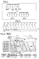
- Fig. 2 is a chart illustrating an exemplary configuration of the switching transmitting antenna elements and receiving antenna elements, including real and synthetic receiving elements, in accordance with one embodiment of the present invention
- Fig. 3 is a signal diagram illustrating an exemplary interleaved simultaneous transmit and receive pulse Doppler (STAR-PD) signal waveform, in accordance with one embodiment of the present invention
- Fig. 4 is a graph illustrating an exemplary transmit-receive time-multiplexing switching and sampling of signals, in accordance with one embodiment of the present invention
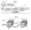
- Fig. 5 is a flow chart illustrating a signal processing algorithm and at least a portion of electronic components of a radar system, including a processor, in accordance with one embodiment of the present invention
- Fig. 6 is an exemplary chart illustrating the de-interleaved A/D data and transformation, in accordance with one embodiment of the present invention
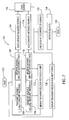
- Fig. 7 is a flow chart illustrating a method of operating a radar system, in accordance with one embodiment of the present invention.
- Fig. 8 is a top plan view of a radar system used with a vehicle, in accordance with one embodiment of the present invention.
- a radar system is generally shown at reference identifier 10.
- the radar system 10 includes a transceiving device generally indicated at 12, a processor 14, and a plurality of antenna elements 16.
- the radar system 10 is an electronically scanned radar system with digital beamforming, according to one embodiment.
- An exemplary electronically scanned radar system with digital beamforming is disclosed in U.S. Patent Application Publication No. 2007/0001897 A1 , entitled "DIGITAL BEAMFORMING FOR AN ELECTRONICALLY SCANNED RADAR SYSTEM" (Atty. Docket No. DP-312498), which is hereby incorporated herein by reference.
- the plurality of antenna elements include a transmitting portion of antenna elements 16A and a receiving portion of antenna elements 16B, such that the receiving portion of antenna elements form a plurality of subarrays that, when the received signals are combined in the processor 14, represent real and synthetic antenna elements.
- the transceiving device 12 is in communication with the receiving antenna elements 16B that receive at least a portion of a plurality of signals transmitted by the transmitting elements 16A.
- the transceiving device 12 is in communication with the transmitting antenna elements 16A and the receiving antenna elements 16B, such that the transceiving device 12 transmits a signal from the transmitting antenna elements 16A, and the transmitted signal propagates in space, reflects off of an object, and is received by the transceiving device 12 through the receiving antenna elements 16B.
- the transceiving device 12 is a single transceiver that transmits and receives signals.
- the transceiving device 12 includes a receiver and a transmitter.
- the transmitting antenna elements 16A are in communication with a switch matrix, wherein a first switch matrix 18A time-multiplexes the transmitting antenna elements 16A, and a second switch matrix 18B time-multiplexes the receiving antenna elements 16B.
- the transceiving device 12 includes the switch matrix.
- the switch matrix can be separate from the transceiving device 12. It should be appreciated by those skilled in the art that the switching matrix can be a single device, including both the first switch matrix 18A and the second switch matrix 18B, or the first and second switch matrices 18A,18B can be separate devices.
- the processor 14 is in communication with the transceiving device 12, wherein the processor 14 digitally beam forms and scans the signals received by the receiving antenna elements 16B.
- the switching transmit antenna elements 16A include first and second switching transmit antenna elements configured and time-multiplexed with respect to the receiving antenna elements 16B, according to one embodiment.
- a receive aperture of the receiving antenna elements 16B increases, such that a first signal transmitted by the first switching transmit antenna element is received by a real antenna element and a second signal transmitted by a second switching transmit antenna element is received by a real antenna element, and the processor 14 combines the received signals, such that the signal received from the first switching transmit antenna represents a signal received by the real receive antenna element and the signal received from the second switching transmit antenna represents a signal received by the synthetic receive antenna element, as described in greater detail herein.
- digital beamforming uses separate transmit and receive antenna elements 16A,16B, wherein the receiving antenna elements 16B are partitioned or separated into a number of subarrays.
- real receive elements are formed by the real receive elements 16B as the first switching transmit antenna of 16A is activated and synthetic receive elements are formed by the real receiving antenna elements 16B as the second switching transmit antenna of 16A is activated, such that the synthetic receive elements are displaced from the real receive elements with respect to the separation of the signals transmitted by the first and second switched transmit antenna elements.
- the two switching transmitting antenna elements 16A are configured and time-multiplexed in relation to the receive elements 16B to effectively double the receive aperture of the receiving antenna elements 16B by a form of synthetic aperture processing in the processor 14.
- Digital beamforming of the signal transmitted from the transmitting portion of antenna elements 16A can use data from the signal received by the real receive element and the signal received by the synthetic receive element to produce a receive element gain and a beamwidth corresponding to the composite real receive element in addition to the synthetic receive element.
- a higher gain, narrow receive beam for improved angle accuracy and discrimination is obtained.
- two of the switching transmit antenna elements 16A are represented in Fig. 2 as reference identifiers T1,T2.
- the first transmit antenna T1 is first selected, and signals are received on the real receiving antenna elements, which are represented in Fig. 2 by reference identifiers R1-R5.
- the second transmit antenna T2 is selected, such that signals are received by the real receiving antenna elements R1-R5.
- the synthetic receiving antenna elements are represented in Fig. 2 as R6-R10.
- the real receiving antenna elements 16B form both the real receive array R1-R5 and the synthetic receive array R6-R10, according to one embodiment.
- the second transmit-receive operation forms a synthetic receive array displaced from the real receive array by a distance determined by the separation of the signals transmitted by the transmit antennas T1,T2, according to one embodiment.
- the real receive antenna elements and synthetic receive antenna elements are the same physical receive antenna elements 16B, and the real receive array is formed by receiving the first transmitted signal and the synthetic receive array is formed by receiving the second transmitted signal, which is transmitted after the first transmitted signal, according to one embodiment.
- Digital beamforming using data from the real and synthetic receive elements produces receive antenna gain and a beamwidth consistent with a total composite aperture dimension (i.e., real plus synthetic).
- the transmitted signals that are transmitted by the switched transmitting antenna elements 16A can be a frequency modulated waveform, according to one embodiment.
- the transmitted signals that are a frequency modulated waveform are simultaneously transmit and receive pulse Doppler (STAR-PD) signals.
- STAR-PD pulse Doppler
- An example of a STAR-PD signal waveform is shown in Fig. 3 .
- a first interleaved STAR-PD signal (Tx 1 ) is transmitted by the first switch antenna element 16A and a substantially identical interleaved STAR-PD signal (Tx 2 ) is transmitted by the second switch transmit antenna element 16A.
- the STAR-PD signal includes substantially identical linear frequency modulated chirps, as shown in Fig. 3 .
- the STAR-PD signal is similar to a frequency modulated continuous wave (FMCW) signal; however, the STAR-PD signal transmitted by the transmitting elements 16A has a steeper frequency modulated slope than a typical FMCW signal, and a large number of identical chirps are used in the STAR-PD signal, according to one embodiment.
- Each chirp of the transmitted STAR-PD signal uses a steep frequency modulated slope, such that a ranging frequency can be much larger than a Doppler frequency component.
- the STAR-PD waveform allows near one hundred percent (100%) duty factor for maximum detection sensitivity while providing independent range and Doppler measurements with adequate false alarm rates.
- the radar system 10 time-multiplexes the transmitting antenna elements and the receiving antenna subarrays in relation to the STAR-PD waveform and samples the received signals, as indicated in Fig. 4 .
- the processor 14 is illustrated in an exemplary embodiment as a digital signal processor (DSP) that processes the received signal, such as the STAR-PD signal, so that each of at least a portion of the chirps of the STAR-PD signal is transformed into range bins for each chirp via a first fast Fourier transform (FFT) process. Then, at least a portion of the range bins are transformed into Doppler bins via a second FFT process by, for a given range bin, using the signals for that range bin from each of the chirps. The transformation of the STAR-PD signals to range and Doppler bins is performed for each receive antenna.
- DSP digital signal processor
- the processor 14 then non-coherently integrates (i.e., sums the amplitude of) the range-Doppler bins across each receive antenna, such that only those bins with detections are transformed into angle bins.
- the digital beam forming FFT can be used to coherently integrate the range-Doppler bins across each receive antenna to transform all bins into angle bins prior to detection.
- using a digital beam forming FFT on all range-Doppler bins can include a greater amount of processing performed by the processor 14 when compared to the process described above.
- the STAR-PD signal can be transformed into range bins, Doppler bins, and angle bins using a discrete Fourier transform (DFT) instead of the FFT for any or all of the individual transformations.
- DFT discrete Fourier transform
- using a DFT typically includes a greater amount of processing performed by the processor 14 when compared to the FFT process described above.
- the sampling interval with respect to a round-trip propagation delay for the transmitted and received signals based upon the maximum range of interest can be dependent upon the STAR-PD waveform parameters, according to one embodiment.
- the transmit antennas typically are not switched during a chirp without compromising the duty factor, the beamforming capability, or a combination thereof.
- the synthetic aperture improvement can be obtained without significantly compromising the duty factor.
- non-interleaved, sequential signals can be transmitted from the transmitting antenna elements. However, transmitting such a non-interleaved, sequential signal can reduce Doppler resolution and accuracy, and degrade beamforming capabilities, when compared to transmitting two substantially identical interleaved signals.
- the processor 14 can include one or more electronic components, one or more software routines, or a combination thereof, to process the signals received from the receiving antenna elements 16B.
- the signals received by the receiving antenna elements 16B are communicated from the transceiving device 12 to an analog-to-digital (A/D) converter 20.
- the output from the A/D converter 20 is communicated to the processor 14.
- the processor 14 includes a de-interleaving function that produces sequential data vectors for each of the chirps for each of the antenna subarrays. An example output of de-interleaving is shown as the input "data cube" in Fig. 6 .
- the processor 14 then forms a ranging FFT, a range cutoff, a Doppler FFT, and a digital beam forming FFT to transform the data from each receive subarray 16B into range-Doppler-angle bins, as illustrated in Fig. 6 , according to one embodiment.
- the range-Doppler bins from each subarray are non-coherently integrated for input to the detection process.
- the digital beamforming FFT can then only be performed on the range-Doppler bins with detections to transform the related data across subarrays into angle bins.
- non-coherent integration across the antenna subarrays prior to detection provides sensitivity gain nearly equal to that obtained with beamforming, but with a substantially reduced processing load, thereby allowing the use of a DSP having a minimal cost, according to one embodiment. It should be appreciated by those skilled in the art that without non-coherent integration, radar sensitivity prior to beamforming generally may not be adequate to meet detection range requirements.
- the processor 14 oversamples the time-multiplexed baseband data by a suitable factor so that the ranging FFT provides range coverage well beyond the maximum range of interest, according to one embodiment.
- the extra range bins are discarded prior to the Doppler FFT in order to provide an adequate range cutoff.
- the oversampling may increase the A/D converter 20 sample rate and the processing load on the ranging FFT to undesirable levels, and thus, it may be difficult to oversample by an amount sufficient to extend the range cutoff to beyond the maximum detection range for all objects in the environment without putting an undesirable processing load on the processor 14.
- the processor 14 uses a combination of oversampling with multi-dwell unfolding. The oversampling is used to set the range cutoff, such that only the largest radar cross-section scatters are detectable beyond the range cutoff, in effect limiting the number and extent of ambiguous interval returns. The multi-dwell unfolding can then be used to reject these returns with adequate false alarm rates, and the processing load of the processor 14 is at an acceptable level.
- the STAR-PD waveform when the transmitted and received signals are STAR-PD waveform signals, the STAR-PD waveform may be ambiguous in Doppler, such that the Doppler interval defined by the chirp spacing may be less than the total required Doppler coverage.
- multi-dwell unfolding can be used to unfold the measured target Doppler.
- the Doppler spread of extended targets is less than their range extents, such that a single set of two dwells with appropriate STAR-PD waveform parameters can be used to both augment range cutoff and perform Doppler unfolding.
- a method of operating the radar system 10 is generally shown at reference identifier 100.
- the method 100 starts at step 102, and proceeds to step 104, wherein the signal is transmitted.
- the signal is transmitted by the first transmitting antenna elements 16A.
- a signal is transmitted, wherein the signal is transmitted by the second transmitting antenna elements 16A, and is substantially identical to the signal transmitted in step 104.
- the signal transmitted at step 104 is received by the receiving antenna elements 16B.
- a signal is received, wherein the received signal is the signal transmitted at step 106.
- the signal received at step 110 is received at a later time than the signal received at step 108. This can be a result of having multiple transmit antenna elements 16A.
- the transmitting and receiving steps 104,106,108,110 continually repeat for each chirp of a STAR-PD signal.
- the received signal that is received at step 108 is converted into a digital signal by the A/D converter 20, according to one embodiment.
- the signals received at step 110 are converted to a digital signal by the A/D converter 20, according to one embodiment.
- the method 100 then proceeds to step 118, wherein the converted digital signals of steps 114,116 are buffered.
- the transmitting and receiving of signals at steps 104,106,108,110, the A/D converting of the received signals at steps 114,116, and the buffering of the signals 118 can be repeated for each dwell of the STAR-PD signal at step 120.
- the converted received signals are processed.
- Objects are then detected at step 124 based upon the processed signals, and the method ends at step 126. It should be appreciated by those skilled in the art that the above steps can be performed substantially simultaneously, such that signals are continuously being transmitted, received, converted, buffered, and processed to detect objects.
- the radar system 10 and method 100 are used with a vehicle 22, as shown in Fig. 8 .
- the radar system 10 and method 100 identify objects in the vehicle's 22 path.
- the signal is transmitted by the transmitting antenna elements 16A and received by the receiving antenna elements 16B, and the processor 14 processes the signals to detect the objects.
- the radar system 10 is a receive digital beamforming (RDBF), electronic scan automotive radar (ESAR). Therefore, the radar system 10 and method 100 can be used to detect objects proximate the vehicle 22, such that predetermined features of the vehicle 22 can be activated based upon the detection of an object. It should be appreciated by those skilled in the art that the radar system 10 and method 100 can be used on other objects or mobile apparatuses.
- the radar system 10 and method 100 have a wide field of view, high update rates, high detection sensitivity, accurate range measurements, Doppler measurements, and angle measurements, multi-target discrimination in range, Doppler and angle, and adequate false alarm rates, wherein the package of the radar system 10 has a reduced size and cost when compared to other types of radar systems.
- the apparent longer receive aperture of the receiving antenna elements 16A typically creates a narrow beamwidth and increases accuracy with a smaller antenna, as compared to an antenna that does not receive a signal that is processed to represent a real and synthetic antenna array. It should be appreciated by those skilled in the art that the radar system 10 and method 100 can include additional or alternative uses and advantages.
Landscapes
- Engineering & Computer Science (AREA)
- Remote Sensing (AREA)
- Radar, Positioning & Navigation (AREA)
- Computer Networks & Wireless Communication (AREA)
- Physics & Mathematics (AREA)
- General Physics & Mathematics (AREA)
- Signal Processing (AREA)
- Astronomy & Astrophysics (AREA)
- Aviation & Aerospace Engineering (AREA)
- Electromagnetism (AREA)
- Radar Systems Or Details Thereof (AREA)
Abstract
Description
- The present invention generally relates to a radar system and method of operating thereof, and more particularly, to a radar system including a method of digital beamforming and detecting targets.
- Generally, some known radar systems achieve angle coverage with multiple signal beams, depending upon the application with which the radar system is used. In such radar systems, a switched beam or mechanically scanned antenna can be incorporated, which can limit performance in one or more ways. One example of such a conventional radar system generally having limited performance is a mechanically scanned antenna that has an update rate that is too slow to achieve wide angle coverage for a particular application. Switched beam radar systems can achieve high update rate, but the number of beams is often limited, resulting in either angle coverage that is too narrow or a beamwidth that is too wide for particular applications.
- Electronically scanned antennas can generally be employed with radar systems. A radar system having an antenna that electronically scans can generally allow for fast scanning, the ability to host multiple antenna beams on the same array, a wide field of view, a narrow beam, and a high update rate. However, electronically scanned antennas typically use discrete phase shifters that are expensive and can introduce excessive radio frequency (RF) loss at particular frequencies, such as 24 GHz and 76 GHz, for example, in automotive radar systems.
- In addition to the excessive RF loss at particular frequencies, using discrete phase shifters can be undesirable in an automotive application due to the cost of such a radar system. Other examples of deficiencies of radar systems used in automobile applications are a limited field of view, an insufficient update rate, inaccuracy, lack of multi-target discrimination, lack of stopped object capability, and inadequate false alarm rates.
- According to one aspect of the present invention, a radar system includes a plurality of antenna elements, wherein the plurality of antenna elements include a first transmitting portion of antenna elements, a second transmitting portion of antenna elements, and a receiving portion of antenna elements, such that the receiving antenna elements form a plurality of subarrays that represent real and synthetic receive antenna elements. The radar system also includes a transceiving device in communication with the receiving portion of antenna elements that receives at least a portion of the plurality of signals transmitted by the transmitting portion of antenna elements including a switching matrix, wherein the switching matrix time-multiplexes the receiving portion of antenna elements. At least the first and second switching transmit antenna elements are configured and time-multiplexed with respect to the receiving portion of the antenna elements, wherein a receive aperture of the receiving portion of the antenna elements is increased. Thus, a first signal transmitted by the first switching transmit antenna element is received by at least one real antenna element and the second signal transmitted by a second switching transmit antenna element is received by at least one real antenna element, wherein the received signals are combined so that the signal received from the first switching transmit antenna element represents a signal received by the real receive antenna element, and the signal received from the second switching transmit antenna element represents a signal received by the synthetic receive antenna element.
- According to another aspect of the present invention, a method of electronically scanning a radar signal is provided. The method includes the steps of transmitting a plurality of signals by a plurality of switching transmit antenna elements, such that a first switching transmit antenna element of the plurality of switching transmit antenna elements transmits a first signal, and switching between the plurality of switching transmit antenna elements, such that a second switching transmit antenna element of the plurality of switching transmit antenna elements transmits a second signal. The method further includes the steps of receiving at least a portion of the transmitted plurality of signals by a transceiving device including a plurality of receiving antenna elements, and time-multiplexing the received signals. Thus, the first transmitted signal is received by at least one real antenna element of the plurality of receiving antenna elements and the second transmitted signal is received by at least one real antenna element of the plurality of receiving antenna elements, wherein, by combining the received signals, a receiving aperture of the receiving portion of the antenna elements is increased, such that the signal received from the first switching transmit antenna represents a signal received by the real receive antenna element, and the signal received from the second switching transmit antenna represents a signal received by the synthetic receive antenna element.
- These and other features, advantages, and objects of the present invention will be further understood and appreciated by those skilled in the art by reference to the following specification, claims, and appended drawings.
- The present invention will now be described, by way of example, with reference to the accompanying drawings, in which:
-
Fig. 1 is a block diagram of a radar system, in accordance with one embodiment of the present invention; -
Fig. 2 is a chart illustrating an exemplary configuration of the switching transmitting antenna elements and receiving antenna elements, including real and synthetic receiving elements, in accordance with one embodiment of the present invention; -
Fig. 3 is a signal diagram illustrating an exemplary interleaved simultaneous transmit and receive pulse Doppler (STAR-PD) signal waveform, in accordance with one embodiment of the present invention; -
Fig. 4 is a graph illustrating an exemplary transmit-receive time-multiplexing switching and sampling of signals, in accordance with one embodiment of the present invention; -
Fig. 5 is a flow chart illustrating a signal processing algorithm and at least a portion of electronic components of a radar system, including a processor, in accordance with one embodiment of the present invention; -
Fig. 6 is an exemplary chart illustrating the de-interleaved A/D data and transformation, in accordance with one embodiment of the present invention; -
Fig. 7 is a flow chart illustrating a method of operating a radar system, in accordance with one embodiment of the present invention; and -
Fig. 8 is a top plan view of a radar system used with a vehicle, in accordance with one embodiment of the present invention. - In reference to
Fig. 1 , a radar system is generally shown atreference identifier 10. Theradar system 10 includes a transceiving device generally indicated at 12, aprocessor 14, and a plurality of antenna elements 16. Thus, theradar system 10 is an electronically scanned radar system with digital beamforming, according to one embodiment. An exemplary electronically scanned radar system with digital beamforming is disclosed inU.S. Patent Application Publication No. 2007/0001897 A1 , entitled "DIGITAL BEAMFORMING FOR AN ELECTRONICALLY SCANNED RADAR SYSTEM" (Atty. Docket No. DP-312498), which is hereby incorporated herein by reference. - According to one embodiment, the plurality of antenna elements include a transmitting portion of
antenna elements 16A and a receiving portion ofantenna elements 16B, such that the receiving portion of antenna elements form a plurality of subarrays that, when the received signals are combined in theprocessor 14, represent real and synthetic antenna elements. Thetransceiving device 12 is in communication with the receivingantenna elements 16B that receive at least a portion of a plurality of signals transmitted by the transmittingelements 16A. Thus, thetransceiving device 12 is in communication with the transmittingantenna elements 16A and the receivingantenna elements 16B, such that thetransceiving device 12 transmits a signal from the transmittingantenna elements 16A, and the transmitted signal propagates in space, reflects off of an object, and is received by thetransceiving device 12 through thereceiving antenna elements 16B. - According to one embodiment, the
transceiving device 12 is a single transceiver that transmits and receives signals. According to an alternate embodiment, thetransceiving device 12 includes a receiver and a transmitter. According to one embodiment, the transmittingantenna elements 16A are in communication with a switch matrix, wherein afirst switch matrix 18A time-multiplexes the transmittingantenna elements 16A, and asecond switch matrix 18B time-multiplexes thereceiving antenna elements 16B. According to one embodiment, thetransceiving device 12 includes the switch matrix. Alternatively, the switch matrix can be separate from thetransceiving device 12. It should be appreciated by those skilled in the art that the switching matrix can be a single device, including both thefirst switch matrix 18A and thesecond switch matrix 18B, or the first andsecond switch matrices - The
processor 14 is in communication with thetransceiving device 12, wherein theprocessor 14 digitally beam forms and scans the signals received by thereceiving antenna elements 16B. The switchingtransmit antenna elements 16A include first and second switching transmit antenna elements configured and time-multiplexed with respect to the receivingantenna elements 16B, according to one embodiment. A receive aperture of the receivingantenna elements 16B increases, such that a first signal transmitted by the first switching transmit antenna element is received by a real antenna element and a second signal transmitted by a second switching transmit antenna element is received by a real antenna element, and theprocessor 14 combines the received signals, such that the signal received from the first switching transmit antenna represents a signal received by the real receive antenna element and the signal received from the second switching transmit antenna represents a signal received by the synthetic receive antenna element, as described in greater detail herein. - According to one embodiment, digital beamforming uses separate transmit and receive
antenna elements antenna elements 16B are partitioned or separated into a number of subarrays. According to one embodiment, real receive elements are formed by the real receiveelements 16B as the first switching transmit antenna of 16A is activated and synthetic receive elements are formed by the real receivingantenna elements 16B as the second switching transmit antenna of 16A is activated, such that the synthetic receive elements are displaced from the real receive elements with respect to the separation of the signals transmitted by the first and second switched transmit antenna elements. Typically, the two switching transmittingantenna elements 16A are configured and time-multiplexed in relation to the receiveelements 16B to effectively double the receive aperture of the receivingantenna elements 16B by a form of synthetic aperture processing in theprocessor 14. Digital beamforming of the signal transmitted from the transmitting portion ofantenna elements 16A can use data from the signal received by the real receive element and the signal received by the synthetic receive element to produce a receive element gain and a beamwidth corresponding to the composite real receive element in addition to the synthetic receive element. Thus, a higher gain, narrow receive beam for improved angle accuracy and discrimination is obtained. - With regards to both
Figs. 1 and2 , two of the switchingtransmit antenna elements 16A are represented inFig. 2 as reference identifiers T1,T2. According to one embodiment, the first transmit antenna T1 is first selected, and signals are received on the real receiving antenna elements, which are represented inFig. 2 by reference identifiers R1-R5. Then, the second transmit antenna T2 is selected, such that signals are received by the real receiving antenna elements R1-R5. The synthetic receiving antenna elements are represented inFig. 2 as R6-R10. Thus, the real receivingantenna elements 16B form both the real receive array R1-R5 and the synthetic receive array R6-R10, according to one embodiment. The second transmit-receive operation forms a synthetic receive array displaced from the real receive array by a distance determined by the separation of the signals transmitted by the transmit antennas T1,T2, according to one embodiment. Thus, the real receive antenna elements and synthetic receive antenna elements are the same physicalreceive antenna elements 16B, and the real receive array is formed by receiving the first transmitted signal and the synthetic receive array is formed by receiving the second transmitted signal, which is transmitted after the first transmitted signal, according to one embodiment. Digital beamforming using data from the real and synthetic receive elements produces receive antenna gain and a beamwidth consistent with a total composite aperture dimension (i.e., real plus synthetic). - The transmitted signals that are transmitted by the switched transmitting
antenna elements 16A can be a frequency modulated waveform, according to one embodiment. By way of explanation and not limitation, the transmitted signals that are a frequency modulated waveform are simultaneously transmit and receive pulse Doppler (STAR-PD) signals. An example of a STAR-PD signal waveform is shown inFig. 3 . According to one embodiment, a first interleaved STAR-PD signal (Tx1) is transmitted by the firstswitch antenna element 16A and a substantially identical interleaved STAR-PD signal (Tx2) is transmitted by the second switch transmitantenna element 16A. - Typically, the STAR-PD signal includes substantially identical linear frequency modulated chirps, as shown in
Fig. 3 . Generally, the STAR-PD signal is similar to a frequency modulated continuous wave (FMCW) signal; however, the STAR-PD signal transmitted by the transmittingelements 16A has a steeper frequency modulated slope than a typical FMCW signal, and a large number of identical chirps are used in the STAR-PD signal, according to one embodiment. Each chirp of the transmitted STAR-PD signal uses a steep frequency modulated slope, such that a ranging frequency can be much larger than a Doppler frequency component. The STAR-PD waveform allows near one hundred percent (100%) duty factor for maximum detection sensitivity while providing independent range and Doppler measurements with adequate false alarm rates. Typically, theradar system 10 time-multiplexes the transmitting antenna elements and the receiving antenna subarrays in relation to the STAR-PD waveform and samples the received signals, as indicated inFig. 4 . - With regards to
Figs. 1-4 , theprocessor 14 is illustrated in an exemplary embodiment as a digital signal processor (DSP) that processes the received signal, such as the STAR-PD signal, so that each of at least a portion of the chirps of the STAR-PD signal is transformed into range bins for each chirp via a first fast Fourier transform (FFT) process. Then, at least a portion of the range bins are transformed into Doppler bins via a second FFT process by, for a given range bin, using the signals for that range bin from each of the chirps. The transformation of the STAR-PD signals to range and Doppler bins is performed for each receive antenna. Theprocessor 14 then non-coherently integrates (i.e., sums the amplitude of) the range-Doppler bins across each receive antenna, such that only those bins with detections are transformed into angle bins. Alternatively, the digital beam forming FFT can be used to coherently integrate the range-Doppler bins across each receive antenna to transform all bins into angle bins prior to detection. However, using a digital beam forming FFT on all range-Doppler bins can include a greater amount of processing performed by theprocessor 14 when compared to the process described above. - According to an alternate embodiment, the STAR-PD signal can be transformed into range bins, Doppler bins, and angle bins using a discrete Fourier transform (DFT) instead of the FFT for any or all of the individual transformations. However, using a DFT typically includes a greater amount of processing performed by the
processor 14 when compared to the FFT process described above. - The sampling interval with respect to a round-trip propagation delay for the transmitted and received signals based upon the maximum range of interest, can be dependent upon the STAR-PD waveform parameters, according to one embodiment. Thus, the transmit antennas typically are not switched during a chirp without compromising the duty factor, the beamforming capability, or a combination thereof. By transmitting two substantially identical interleaved STAR-PD waveforms for each transmitting antenna element, the synthetic aperture improvement can be obtained without significantly compromising the duty factor. According to an alternate embodiment, non-interleaved, sequential signals can be transmitted from the transmitting antenna elements. However, transmitting such a non-interleaved, sequential signal can reduce Doppler resolution and accuracy, and degrade beamforming capabilities, when compared to transmitting two substantially identical interleaved signals.
- In reference to
Fig. 5 , theprocessor 14 can include one or more electronic components, one or more software routines, or a combination thereof, to process the signals received from the receivingantenna elements 16B. According to one embodiment, the signals received by the receivingantenna elements 16B are communicated from thetransceiving device 12 to an analog-to-digital (A/D)converter 20. The output from the A/D converter 20 is communicated to theprocessor 14. Theprocessor 14 includes a de-interleaving function that produces sequential data vectors for each of the chirps for each of the antenna subarrays. An example output of de-interleaving is shown as the input "data cube" inFig. 6 . - The
processor 14 then forms a ranging FFT, a range cutoff, a Doppler FFT, and a digital beam forming FFT to transform the data from each receivesubarray 16B into range-Doppler-angle bins, as illustrated inFig. 6 , according to one embodiment. According to an alternate embodiment, the range-Doppler bins from each subarray are non-coherently integrated for input to the detection process. The digital beamforming FFT can then only be performed on the range-Doppler bins with detections to transform the related data across subarrays into angle bins. Thus, the use of non-coherent integration across the antenna subarrays prior to detection provides sensitivity gain nearly equal to that obtained with beamforming, but with a substantially reduced processing load, thereby allowing the use of a DSP having a minimal cost, according to one embodiment. It should be appreciated by those skilled in the art that without non-coherent integration, radar sensitivity prior to beamforming generally may not be adequate to meet detection range requirements. - Since the composite, time-multiplexed video bandwidth for a predetermined target range is typically greater than the target ranging frequency, the conventional approach of using a low pass filter for range cutoff does not apply. Instead, the
processor 14 oversamples the time-multiplexed baseband data by a suitable factor so that the ranging FFT provides range coverage well beyond the maximum range of interest, according to one embodiment. - According to one embodiment, the extra range bins are discarded prior to the Doppler FFT in order to provide an adequate range cutoff. According to an alternate embodiment, the oversampling may increase the A/
D converter 20 sample rate and the processing load on the ranging FFT to undesirable levels, and thus, it may be difficult to oversample by an amount sufficient to extend the range cutoff to beyond the maximum detection range for all objects in the environment without putting an undesirable processing load on theprocessor 14. In this embodiment, theprocessor 14 uses a combination of oversampling with multi-dwell unfolding. The oversampling is used to set the range cutoff, such that only the largest radar cross-section scatters are detectable beyond the range cutoff, in effect limiting the number and extent of ambiguous interval returns. The multi-dwell unfolding can then be used to reject these returns with adequate false alarm rates, and the processing load of theprocessor 14 is at an acceptable level. - According to one embodiment, when the transmitted and received signals are STAR-PD waveform signals, the STAR-PD waveform may be ambiguous in Doppler, such that the Doppler interval defined by the chirp spacing may be less than the total required Doppler coverage. Thus, multi-dwell unfolding can be used to unfold the measured target Doppler. By way of explanation and not limitation, in a dense, distributed target environment, the Doppler spread of extended targets is less than their range extents, such that a single set of two dwells with appropriate STAR-PD waveform parameters can be used to both augment range cutoff and perform Doppler unfolding.
- With regards to
Fig. 7 , a method of operating theradar system 10 is generally shown atreference identifier 100. Themethod 100 starts atstep 102, and proceeds to step 104, wherein the signal is transmitted. According to one embodiment, the signal is transmitted by the first transmittingantenna elements 16A. Atstep 106, a signal is transmitted, wherein the signal is transmitted by the second transmittingantenna elements 16A, and is substantially identical to the signal transmitted instep 104. - At
step 108, the signal transmitted atstep 104 is received by the receivingantenna elements 16B. Atstep 110, a signal is received, wherein the received signal is the signal transmitted atstep 106. Typically, the signal received atstep 110 is received at a later time than the signal received atstep 108. This can be a result of having multiple transmitantenna elements 16A. According to one embodiment, atstep 112, the transmitting and receiving steps 104,106,108,110 continually repeat for each chirp of a STAR-PD signal. - At
step 114, the received signal that is received atstep 108 is converted into a digital signal by the A/D converter 20, according to one embodiment. Atstep 116, the signals received atstep 110 are converted to a digital signal by the A/D converter 20, according to one embodiment. Themethod 100 then proceeds to step 118, wherein the converted digital signals of steps 114,116 are buffered. According to one embodiment, the transmitting and receiving of signals at steps 104,106,108,110, the A/D converting of the received signals at steps 114,116, and the buffering of thesignals 118 can be repeated for each dwell of the STAR-PD signal atstep 120. - At
step 122, the converted received signals are processed. Objects are then detected atstep 124 based upon the processed signals, and the method ends atstep 126. It should be appreciated by those skilled in the art that the above steps can be performed substantially simultaneously, such that signals are continuously being transmitted, received, converted, buffered, and processed to detect objects. - By way of explanation and not limitation, in operation and in reference to
Figs. 1-8 , theradar system 10 andmethod 100 are used with avehicle 22, as shown inFig. 8 . According to one embodiment, theradar system 10 andmethod 100 identify objects in the vehicle's 22 path. Thus, the signal is transmitted by the transmittingantenna elements 16A and received by the receivingantenna elements 16B, and theprocessor 14 processes the signals to detect the objects. According to one embodiment, theradar system 10 is a receive digital beamforming (RDBF), electronic scan automotive radar (ESAR). Therefore, theradar system 10 andmethod 100 can be used to detect objects proximate thevehicle 22, such that predetermined features of thevehicle 22 can be activated based upon the detection of an object. It should be appreciated by those skilled in the art that theradar system 10 andmethod 100 can be used on other objects or mobile apparatuses. - Advantageously, the
radar system 10 andmethod 100 have a wide field of view, high update rates, high detection sensitivity, accurate range measurements, Doppler measurements, and angle measurements, multi-target discrimination in range, Doppler and angle, and adequate false alarm rates, wherein the package of theradar system 10 has a reduced size and cost when compared to other types of radar systems. The apparent longer receive aperture of the receivingantenna elements 16A typically creates a narrow beamwidth and increases accuracy with a smaller antenna, as compared to an antenna that does not receive a signal that is processed to represent a real and synthetic antenna array. It should be appreciated by those skilled in the art that theradar system 10 andmethod 100 can include additional or alternative uses and advantages. - The above description is considered that of preferred embodiments only. Modifications of the invention will occur to those skilled in the art and to those who make or use the invention. Therefore, it is understood that the embodiments shown in the drawings and described above are merely for illustrative purposes and not intended to limit the scope of the invention, which is defined by the following claims as interpreted according to the principles of patent law, including the doctrine of equivalents.
Claims (20)
- A radar system (10) comprising:a plurality of antenna elements comprising:a first transmit antenna element (16A);a second transmit antenna element (16A); anda receiving portion of antenna elements (16B), such that said receiving antenna elements (16B) form a plurality of subarrays that represent real (R1-R5) and synthetic (R6-R10) receive antenna elements;a transceiving device (12) comprising a switching matrix (18A,18B), wherein said transceiving device (12) is in communication with said transmitting portion of antenna elements (16A) and said receiving portion of antenna elements (16B) that receives at least a portion of said plurality of signals transmitted by said transmitting portion of antenna elements (16A), and said switching matrix (18A,18B) time-multiplexes said transmitting and receiving portion of antenna elements (16A,16B); andat least said first and second switching transmit antenna elements (16A) configured and time-multiplexed with respect to said receiving portion of said antenna elements (16B), such that a first signal transmitted by said first switching transmit antenna element (16A) is received by at least one said real antenna element (R1-R5) and a second signal transmitted by said second switching transmit antenna element (16A) is received by at least one said real antenna element (R1-R5), and wherein said received signals are combined so that said signal received from said first switching transmit antenna element (16A) represents a signal received by said real receive antenna element (R1-R5) and said signal received from said second switching transmit antenna element (16A) represents a signal received by said synthetic receive antenna element (R6-R10), wherein a receive aperture of said receiving portion of antenna elements (16B) is increased.
- The radar system (10) of claim 1 further comprising a processor (14) in communication with said transceiving device (12), wherein said processor (14) beam forms and scans said signals received by said receiving portion of antenna elements (16B).
- The radar system (10) of claim 1, wherein said increased receive aperture forms a narrow beamwidth of said signal transmitted by said transmitting portion of antenna elements (16A).
- The radar system (10) of claim 1, wherein said synthetic antenna elements (R6-R10) are displaced from said real antenna elements (R1-R5) with respect to a predetermined distance between said signals transmitted by said first and second switched transmit antenna elements (16A).
- The radar system (10) of claim 1, wherein digital beamforming of said signal transmitted from said transmitting portion of antenna elements (16A) using data from said signals received by said real receive elements (R1-R5) and said signals received by said synthetic receive elements (R6-R10), produces a receive antenna gain and beamwidth corresponding to said real receive elements (R1-R5) in addition to said synthetic receive elements (R6-R10).
- The radar system (10) of claim 1, wherein said transmitted signals are a simultaneous transmit and receive pulse Doppler (STAR-PD) frequency modulated waveform.
- The radar system (10) of claim 6, wherein a first interleaved STAR-PD signal is transmitted by said first switching transmit antenna element (16A) and a substantially identical interleaved STAR-PD signal is transmitted by said second switching transmit antenna element (16A).
- The radar system (10) of claim 6, wherein said STAR-PD signal comprises substantially identical linear frequency modulated chirps, and a processor (14) processes said STAR-PD signal, such that each of at least a portion of said chirps is transformed into range bins for each chirp and at least a portion of said range bins are transformed into Doppler bins.
- The radar system (10) of claim 8, wherein said processor (14) non-coherently integrates said range-Doppler bins and performs detection substantially prior to digital beamforming, such that transformation into angle bins is substantially limited to said range-Doppler bins with detections.
- The radar system (10) of claim 1, wherein a processor (14) oversamples time-multiplexed baseband data by a predetermined factor for range cutoff of said received signals.
- The radar system (10) of claim 10, wherein said oversampled time-multiplexed baseband data is combined with multi-dwell unfolding, for range cutoff of said received signals and range-Doppler unfolding.
- The radar system (10) of claim 1, wherein said transceiving device (12) down-converts and samples said time-interleaved data within a signal received from each said antenna element of said receiving portion of antenna elements (16B).
- The radar system (10) of claim 1, wherein a processor (14) beam forms and scans said signal by combining sampled data of said signal from each said antenna element of said receiving portion of antenna elements (16B) with amplitude and phase weighting.
- A method (100) of electronically scanning a radar signal, said method (100) comprising the steps of:transmitting a plurality of signals by a plurality of switching transmit antenna elements (16A), such that a first switching transmit antenna element of said plurality of switching transmit antenna elements transmits a first signal (104);switching between said plurality of switching transmit antenna elements (16A), such that a second switching transmit antenna element (16A) of said plurality of switching transmit antenna elements (16A) transmits a second signal (106);receiving (108,110) at least a portion of said transmitted plurality of signals by a transceiving device (12) comprising a plurality of receiving antenna elements (16B);time-multiplexing said received signals, such that said first transmitted signal is received by at least one real antenna element (R1-R5) of said plurality of receiving antenna elements (16B) and said second transmitted signal is received by at least one real antenna element (R1-R5) of said plurality of receiving antenna elements (16B), and combining said received signals, such that the signal received from said first switching transmit antenna element (16A) represents a signal received by said real receive antenna element (R1-R5), and the signal received from said second switching transmit antenna element (16A) represents a signal received by said synthetic receive antenna element (R6-R10), wherein a receiving aperture of said plurality of receiving antenna elements (16B) is increased.
- The method (100) of claim 14, wherein said increased receive aperture forms a narrow beamwidth of said signal transmitted by said transmitting portion of antenna elements (16A).
- The method (100) of claim 14, wherein synthetic receive elements (R6-R10) are displaced from real receive elements (R1-R5) with respect to a predetermined distance between said signals transmitted by said first and second switching transmit antenna elements (16A).
- The method (100) of claim 14, wherein said step of forming a beam comprises digitally beamforming said signals received by said real receive elements (R1-R5) and said signals received by said synthetic receive elements (R6-R10), to produce a receive antenna gain corresponding to said real receive elements (R1-R5) in addition to said synthetic receive elements (R6-R10).
- The method (100) of claim 14, wherein said transmitted signals are a simultaneous transmit and receive pulse Doppler (STAR-PD) frequency modulated waveform.
- The method (100) of claim 14 further comprising the step of oversampling said time-multiplexed baseband data by a predetermined factor.
- The method (100) of claim 14 further comprising the step of downconverting and sampling said time-interleaved data within signal received from each said receiving antenna element (16B), and beamforming and scanning said signal by combining sampled data of said signal from each said receiving antenna element (16B) with amplitude and phase weighting.
Applications Claiming Priority (2)
| Application Number | Priority Date | Filing Date | Title |
|---|---|---|---|
| US99554907P | 2007-09-27 | 2007-09-27 | |
| US12/072,794 US7639171B2 (en) | 2007-09-27 | 2008-02-28 | Radar system and method of digital beamforming |
Publications (1)
| Publication Number | Publication Date |
|---|---|
| EP2045877A1 true EP2045877A1 (en) | 2009-04-08 |
Family
ID=40019450
Family Applications (1)
| Application Number | Title | Priority Date | Filing Date |
|---|---|---|---|
| EP08163981A Withdrawn EP2045877A1 (en) | 2007-09-27 | 2008-09-09 | Radar system and method of digital beamforming |
Country Status (2)
| Country | Link |
|---|---|
| US (1) | US7639171B2 (en) |
| EP (1) | EP2045877A1 (en) |
Cited By (10)
| Publication number | Priority date | Publication date | Assignee | Title |
|---|---|---|---|---|
| WO2011101225A1 (en) * | 2010-02-16 | 2011-08-25 | Astyx Gmbh | Device and method for measuring distance and speed |
| WO2015188987A1 (en) * | 2014-06-10 | 2015-12-17 | Robert Bosch Gmbh | Method for locating an object using a fmcw-radar |
| EP2983007A1 (en) * | 2014-08-05 | 2016-02-10 | Panasonic Intellectual Property Management Co., Ltd. | Radar apparatus and object sensing method |
| CN105932427A (en) * | 2016-05-04 | 2016-09-07 | 西安电子工程研究所 | Millimeter-wave imaging radar one-dimensional array antenna and sequential control method |
| EP3098623A1 (en) * | 2015-05-25 | 2016-11-30 | Autoliv Development AB | A vehicle radar system |
| CN106405511A (en) * | 2015-06-26 | 2017-02-15 | 德尔福技术有限公司 | Radar Signal Processing for Autonomous Vehicles |
| JP6174835B1 (en) * | 2017-05-12 | 2017-08-02 | ムサシノ機器株式会社 | Liquid level alarm device, fault detection method for liquid level alarm device |
| CN108152809A (en) * | 2016-12-06 | 2018-06-12 | 通用汽车环球科技运作有限责任公司 | Direct no doppler velocity in linear FM radar measures |
| EP3816667A1 (en) * | 2019-10-30 | 2021-05-05 | NXP USA, Inc. | Systems and methods for automotive synthetic aperture radar |
| WO2021230924A1 (en) * | 2020-05-15 | 2021-11-18 | Raytheon Company | Beamformer for digital array |
Families Citing this family (84)
| Publication number | Priority date | Publication date | Assignee | Title |
|---|---|---|---|---|
| US8576768B2 (en) * | 2009-04-16 | 2013-11-05 | Qualcomm Incorporated | Hybrid multi-band receiver |
| JP4877364B2 (en) * | 2009-07-10 | 2012-02-15 | トヨタ自動車株式会社 | Object detection device |
| DE112009005279T5 (en) * | 2009-09-25 | 2013-01-03 | Toyota Jidosha Kabushiki Kaisha | VEHICLE RADAR DEVICE |
| JP5492135B2 (en) * | 2011-04-06 | 2014-05-14 | 株式会社東芝 | Radar apparatus and received data processing method |
| US20120274499A1 (en) * | 2011-04-29 | 2012-11-01 | Spatial Digital Systems | Radar imaging via spatial spectrum measurement and MIMO waveforms |
| WO2012169052A1 (en) | 2011-06-09 | 2012-12-13 | トヨタ自動車株式会社 | Other-vehicle detection device and other-vehicle detection method |
| DE102011113015A1 (en) * | 2011-09-09 | 2013-03-14 | Astyx Gmbh | Imaging radar sensor with synthetic magnification of the antenna taper and two-dimensional beam sweep |
| US9116227B2 (en) | 2012-02-22 | 2015-08-25 | Toyota Motor Engineering & Manufacturing North America, Inc. | Hybrid radar integrated into single package |
| US8988278B2 (en) | 2012-07-23 | 2015-03-24 | Toyota Motor Engineering & Manufacturing North America, Inc. | Digital beam forming using phased array architecture |
| DE102014212280A1 (en) * | 2014-06-26 | 2015-12-31 | Robert Bosch Gmbh | Radar measurement method |
| US9389305B2 (en) * | 2013-02-27 | 2016-07-12 | Mitsubishi Electric Research Laboratories, Inc. | Method and system for compressive array processing |
| US9395727B1 (en) | 2013-03-22 | 2016-07-19 | Google Inc. | Single layer shared aperture beam forming network |
| US9638789B2 (en) | 2014-01-30 | 2017-05-02 | Infineon Technologies Ag | Method, device and system for processing radar signals |
| US9310468B2 (en) | 2014-05-15 | 2016-04-12 | Delphi Technologies, Inc. | Radar system with improved multi-target discrimination |
| US9841497B2 (en) * | 2014-06-05 | 2017-12-12 | Infineon Technologies Ag | Method, device and system for processing radar signals |
| JP6364986B2 (en) | 2014-06-13 | 2018-08-01 | 株式会社デンソー | Radar equipment |
| US9541637B2 (en) * | 2014-07-29 | 2017-01-10 | Delphi Technologies, Inc. | Radar data compression system and method |
| US9470777B2 (en) * | 2014-09-19 | 2016-10-18 | Delphi Technologies, Inc. | Radar system for automated vehicle with phase change based target catagorization |
| DE102014116452B4 (en) * | 2014-11-11 | 2022-10-27 | Infineon Technologies Ag | Method and device for processing radar signals |
| JP6381454B2 (en) * | 2015-02-13 | 2018-08-29 | 三菱電機株式会社 | Radar equipment |
| DE102015211490A1 (en) * | 2015-06-22 | 2016-12-22 | Robert Bosch Gmbh | Method for operating a radar device |
| EP3144696A1 (en) | 2015-09-15 | 2017-03-22 | Delphi Technologies, Inc. | Radar system for automated vehicle with phase change based target categorization |
| US10078131B2 (en) * | 2015-09-15 | 2018-09-18 | Texas Instruments Incorporated | Method and apparatus for FMCW radar processing |
| CN105356069B (en) * | 2015-11-28 | 2018-12-04 | 成都安智杰科技有限公司 | A kind of raising method and antenna structure of the trailer-mounted radar measurement angle without fuzzy ranges |
| US10743272B2 (en) * | 2016-02-16 | 2020-08-11 | Cable Television Laboratories, Inc. | Coordinated beamforming |
| DE102016109910B4 (en) * | 2016-05-30 | 2017-12-07 | Infineon Technologies Ag | Radar systems and method for operating a radar system |
| US10330773B2 (en) * | 2016-06-16 | 2019-06-25 | Texas Instruments Incorporated | Radar hardware accelerator |
| EP3907529A1 (en) * | 2016-07-01 | 2021-11-10 | Veoneer Sweden AB | A vehicle radar for environmental detection |
| IL250253B (en) | 2017-01-24 | 2021-10-31 | Arbe Robotics Ltd | Method for separating targets and clutter from noise in radar signals |
| US11073611B2 (en) | 2017-03-20 | 2021-07-27 | International Business Machines Corporation | High spatial resolution 3D radar based on a single sensor |
| WO2019009344A1 (en) * | 2017-07-04 | 2019-01-10 | 日本電気株式会社 | Object detection device, object detection method, and computer-readable recording medium |
| DE102017119624A1 (en) * | 2017-08-28 | 2019-04-18 | HELLA GmbH & Co. KGaA | Method for operating a radar system of a vehicle |
| DE102017221120B4 (en) * | 2017-11-27 | 2025-03-27 | Zf Friedrichshafen Ag | Evaluation procedure for RADAR measurement data from a mobile RADAR measurement system |
| IL255982A (en) | 2017-11-29 | 2018-01-31 | Arbe Robotics Ltd | Detection, mitigation and avoidance of mutual interference between automotive radars |
| IL259190A (en) * | 2018-05-07 | 2018-06-28 | Arbe Robotics Ltd | System and method for frequency hopping MIMO FMCW imaging radar |
| US10281572B1 (en) | 2018-05-24 | 2019-05-07 | Delphi Technologies, Llc | Phase correction for object detection including TDMA |
| IL260694A (en) * | 2018-07-19 | 2019-01-31 | Arbe Robotics Ltd | Apparatus and method of two-stage signal processing in a radar system |
| IL260695A (en) | 2018-07-19 | 2019-01-31 | Arbe Robotics Ltd | Apparatus and method of eliminating settling time delays in a radar system |
| IL260696A (en) | 2018-07-19 | 2019-01-31 | Arbe Robotics Ltd | Apparatus and method of rf built in self-test (rfbist) in a radar system |
| US10962636B2 (en) * | 2018-08-13 | 2021-03-30 | GM Global Technology Operations LLC | Range and direction of arrival migration with doppler ambiguity estimation |
| IL261636A (en) | 2018-09-05 | 2018-10-31 | Arbe Robotics Ltd | Skewed mimo antenna array for use in automotive imaging radar |
| US11092686B2 (en) * | 2018-09-19 | 2021-08-17 | Steradian Semiconductors Private Limited | Method, apparatus and device for doppler compensation in a time switched MIMO radar system |
| KR102194320B1 (en) * | 2018-11-30 | 2020-12-22 | 이화여자대학교 산학협력단 | Apparatus and Method for Tracking Object based on Radar Image Reconstruction |
| US11262434B2 (en) * | 2019-04-01 | 2022-03-01 | GM Global Technology Operations LLC | Antenna array design and processing to eliminate false detections in a radar system |
| US11391836B2 (en) * | 2019-04-10 | 2022-07-19 | Qualcomm Incorporated | Liveliness detection using radar |
| US11181614B2 (en) * | 2019-06-06 | 2021-11-23 | GM Global Technology Operations LLC | Antenna array tilt and processing to eliminate false detections in a radar system |
| US11821977B2 (en) * | 2019-07-10 | 2023-11-21 | Samsung Electronics Co., Ltd. | Target detection and tracking for feature extraction |
| JP2019194627A (en) * | 2019-08-05 | 2019-11-07 | 日本無線株式会社 | Radar signal processor and radar device |
| DE102019124850B4 (en) * | 2019-09-16 | 2021-08-12 | Infineon Technologies Ag | Phase optimization for improved detection of radar targets |
| IL271269A (en) | 2019-12-09 | 2021-06-30 | Arbe Robotics Ltd | Radome for automotive radar patch antenna |
| US12164057B2 (en) * | 2019-12-16 | 2024-12-10 | Ay Dee Kay Llc | Calibrating array antennas based on signal energy distribution as a function of angle |
| EP3839561A1 (en) * | 2019-12-18 | 2021-06-23 | Imec VZW | Radar ranging |
| KR102982738B1 (en) * | 2019-12-26 | 2026-06-26 | 삼성전자주식회사 | Method and device to process radar signal |
| EP3862772A1 (en) * | 2020-02-04 | 2021-08-11 | Aptiv Technologies Limited | Radar device |
| CN113841341B (en) * | 2020-03-26 | 2023-03-10 | 华为技术有限公司 | Wireless communication device and antenna switching method thereof |
| US11860270B2 (en) | 2020-04-01 | 2024-01-02 | The Board Of Trustees Of The University Of Alabama | Sparse linear array approach in automotive radars using matrix completion |
| US11239903B2 (en) * | 2020-04-08 | 2022-02-01 | Sprint Communications Company L.P. | Uplink beamforming between an airborne transceiver and a terrestrial transceiver |
| EP3905105B1 (en) | 2020-04-27 | 2026-06-24 | Aptiv Technologies AG | Method for determining a collision free space |
| EP3923023A3 (en) * | 2020-05-20 | 2022-03-09 | Infineon Technologies AG | Processing radar signals |
| DE112020007233T5 (en) | 2020-05-25 | 2023-03-16 | Mitsubishi Electric Corporation | radar device |
| US11644565B2 (en) | 2020-10-13 | 2023-05-09 | Aptiv Technologies Limited | Radar system with sparse primary array and dense auxiliary array |
| DE102020127177B4 (en) * | 2020-10-15 | 2026-07-16 | Infineon Technologies Ag | RADAR DEVICE AND METHOD FOR DETECTING RADAR TARGETS |
| US11619705B2 (en) | 2020-10-20 | 2023-04-04 | Aptiv Technologies Limited | Radar system with modified orthogonal linear antenna subarrays |
| IL278587A (en) | 2020-11-09 | 2022-06-01 | Arbe Robotics Ltd | Efficient direction of arrival estimation using low rank approximation |
| EP4001962A1 (en) | 2020-11-23 | 2022-05-25 | Aptiv Technologies Limited | Free space determining device, free space determining method and free space determining program |
| EP4009228B1 (en) | 2020-12-02 | 2025-10-29 | Aptiv Technologies AG | Method for determining a semantic free space |
| US12153157B2 (en) | 2021-01-27 | 2024-11-26 | Aptiv Technologies AG | Radar system with paired one-dimensional and two-dimensional antenna arrays |
| US11714180B2 (en) | 2021-01-29 | 2023-08-01 | Aptiv Technologies Limited | Radar system to detect angles in bistatic and monostatic scenarios |
| GB2603476A (en) | 2021-02-02 | 2022-08-10 | Aptiv Tech Ltd | Object detection with multiple ranges and resolutions |
| US11808846B2 (en) * | 2021-02-12 | 2023-11-07 | Aptiv Technologies Limited | Angle-finding process for sparse uniform arrays |
| EP4047553A1 (en) | 2021-02-19 | 2022-08-24 | Aptiv Technologies Limited | Motion compensation and refinement in recurrent neural networks |
| US11754683B2 (en) * | 2021-05-10 | 2023-09-12 | nEYE Systems, Inc. | Pseudo monostatic LiDAR with two-dimensional silicon photonic mems switch array |
| US12216199B2 (en) | 2021-07-15 | 2025-02-04 | Aptiv Technologies AG | De-aliased imaging for a synthetic aperture radar |
| EP4130789B1 (en) * | 2021-08-03 | 2026-03-11 | GM Cruise Holdings LLC | Radar system that uses velocity labeled multiplexing for generating detections |
| US11536801B1 (en) * | 2021-10-27 | 2022-12-27 | Aurora Operations, Inc. | Vehicle radar sensor utilizing non-uniform frequency modulated continuous wave (FMCW) chirps |
| EP4191274B1 (en) | 2021-12-03 | 2026-04-08 | Aptiv Technologies AG | Radar-based estimation of the height of an object |
| EP4198553A1 (en) | 2021-12-20 | 2023-06-21 | Aptiv Technologies Limited | Method, device and program for estimating object reflectivity in a lidar system |
| US12216227B2 (en) | 2022-01-19 | 2025-02-04 | Aptiv Technologies AG | Radar system with sequential two-dimensional angle estimation |
| GB2615100A (en) | 2022-01-27 | 2023-08-02 | Aptiv Tech Ltd | Method of determining a point of interest and/or a road type in a map, and related cloud server and vehicle |
| US12493112B2 (en) | 2022-09-19 | 2025-12-09 | Aptiv Technologies AG | Multiple-target, simultaneous beamforming for four-dimensional radar systems |
| US12560695B2 (en) | 2023-01-17 | 2026-02-24 | Aptiv Technologies AG | Radar system to jointly detect direction-of-arrival and direction-of-departure angles in multipath scenarios |
| US12392879B2 (en) | 2023-02-28 | 2025-08-19 | Aptiv Technologies AG | Radar system to universally detect direction-of-arrival or direction-of-departure angles in direct-path and multipath reflection conditions |
| US20250306164A1 (en) * | 2024-03-14 | 2025-10-02 | Mitsubishi Electric Research Laboratories, Inc. | System and Method for DMG Passive Sensing in an Environment |
| US20260177657A1 (en) * | 2024-12-19 | 2026-06-25 | Intel Corporation | Method and apparatus for radar sensing in a disaggregated radio access network |
Citations (3)
| Publication number | Priority date | Publication date | Assignee | Title |
|---|---|---|---|---|
| EP1486796A2 (en) * | 2003-06-09 | 2004-12-15 | Fujitsu Ten Limited | Radar device with switch matrix for adaptive beamforming in receive path and switching of transmit path |
| EP1650579A1 (en) * | 2004-09-29 | 2006-04-26 | Fujitsu Limited | Switchable antenna array for estimating the direction of arrival of a received signal |
| US20070001897A1 (en) | 2005-07-01 | 2007-01-04 | Alland Stephen W | Digital beamforming for an electronically scanned radar system |
Family Cites Families (28)
| Publication number | Priority date | Publication date | Assignee | Title |
|---|---|---|---|---|
| US3276019A (en) | 1964-02-11 | 1966-09-27 | Gen Precision Inc | Combined sequential beam switcher and duplexer using microwave circulators |
| US3803625A (en) | 1972-12-18 | 1974-04-09 | Itt | Network approach for reducing the number of phase shifters in a limited scan phased array |
| US3833904A (en) | 1973-02-05 | 1974-09-03 | Hughes Aircraft Co | Airborne switched array radar system |
| US4041501A (en) | 1975-07-10 | 1977-08-09 | Hazeltine Corporation | Limited scan array antenna systems with sharp cutoff of element pattern |
| US4103302A (en) | 1976-07-16 | 1978-07-25 | General Electric Company | Velocity and drift angle tracking system using altimetry signals |
| GB2072986B (en) | 1980-03-26 | 1984-06-13 | Standard Telephones Cables Ltd | Phased array signal processing |
| CA1159934A (en) | 1980-05-15 | 1984-01-03 | Zdzistaw A.A. Krajewski | Cancellation of group delay error by dual speed of rotation |
| CA1238713A (en) | 1984-06-04 | 1988-06-28 | Alliedsignal Inc. | Antenna feed network |
| US4962381A (en) | 1989-04-11 | 1990-10-09 | General Electric Company | Systolic array processing apparatus |
| US5103233A (en) | 1991-04-16 | 1992-04-07 | General Electric Co. | Radar system with elevation-responsive PRF control, beam multiplex control, and pulse integration control responsive to azimuth angle |
| US5307073A (en) | 1992-11-13 | 1994-04-26 | General Electric Co. | Optically controlled phased array radar |
| US6018317A (en) | 1995-06-02 | 2000-01-25 | Trw Inc. | Cochannel signal processing system |
| US5657026A (en) | 1996-01-26 | 1997-08-12 | Electronic Tracking Systems, Inc. | Beacon signal receiving system |
| WO1997040400A1 (en) * | 1996-04-22 | 1997-10-30 | The Furukawa Electric Co., Ltd. | Radar |
| US6292433B1 (en) | 1997-02-03 | 2001-09-18 | Teratech Corporation | Multi-dimensional beamforming device |
| NL1005755C2 (en) | 1997-04-08 | 1998-10-09 | Hollandse Signaalapparaten Bv | Apparatus for controlling radar transmissions for a system of antennas on a movable platform. |
| WO2000079702A1 (en) | 1999-06-23 | 2000-12-28 | Japan As Represented By President Of Hokkaido University | Radio device |
| US6823170B1 (en) | 2000-07-26 | 2004-11-23 | Ericsson Inc. | Satellite communications system using multiple earth stations |
| US6559797B1 (en) | 2001-02-05 | 2003-05-06 | Hughes Electronics Corporation | Overlapping subarray patch antenna system |
| CA2466655A1 (en) | 2001-11-09 | 2003-05-22 | Ems Technologies, Inc. | Beamformer for multi-beam receive antenna |
| US6750810B2 (en) * | 2001-12-18 | 2004-06-15 | Hitachi, Ltd. | Monopulse radar system |
| US6661376B2 (en) | 2002-01-18 | 2003-12-09 | Northrop Grumman Corporation | Tiled antenna with overlapping subarrays |
| US6999724B2 (en) | 2002-06-20 | 2006-02-14 | Lucent Technologies Inc. | Slowing the observed rate of channel fluctuations in a multiple antenna system |
| JP4190335B2 (en) | 2003-04-03 | 2008-12-03 | 富士通テン株式会社 | Radar apparatus and signal processing method thereof |
| KR100574228B1 (en) | 2003-12-27 | 2006-04-26 | 한국전자통신연구원 | Hexagonal arrangement of dielectric rods to form flat-top element patterns |
| KR100783476B1 (en) * | 2004-06-21 | 2007-12-07 | 후지쓰 텐 가부시키가이샤 | Radar device |
| US7489270B2 (en) | 2005-04-15 | 2009-02-10 | Novariant, Inc. | GNSS line bias measurement system and method |
| US20080100510A1 (en) * | 2006-10-27 | 2008-05-01 | Bonthron Andrew J | Method and apparatus for microwave and millimeter-wave imaging |
-
2008
- 2008-02-28 US US12/072,794 patent/US7639171B2/en active Active
- 2008-09-09 EP EP08163981A patent/EP2045877A1/en not_active Withdrawn
Patent Citations (3)
| Publication number | Priority date | Publication date | Assignee | Title |
|---|---|---|---|---|
| EP1486796A2 (en) * | 2003-06-09 | 2004-12-15 | Fujitsu Ten Limited | Radar device with switch matrix for adaptive beamforming in receive path and switching of transmit path |
| EP1650579A1 (en) * | 2004-09-29 | 2006-04-26 | Fujitsu Limited | Switchable antenna array for estimating the direction of arrival of a received signal |
| US20070001897A1 (en) | 2005-07-01 | 2007-01-04 | Alland Stephen W | Digital beamforming for an electronically scanned radar system |
Cited By (24)
| Publication number | Priority date | Publication date | Assignee | Title |
|---|---|---|---|---|
| WO2011101225A1 (en) * | 2010-02-16 | 2011-08-25 | Astyx Gmbh | Device and method for measuring distance and speed |
| CN106461759A (en) * | 2014-06-10 | 2017-02-22 | 罗伯特·博世有限公司 | Method for locating an object using a fmcw-radar |
| WO2015188987A1 (en) * | 2014-06-10 | 2015-12-17 | Robert Bosch Gmbh | Method for locating an object using a fmcw-radar |
| CN106461759B (en) * | 2014-06-10 | 2020-03-20 | 罗伯特·博世有限公司 | Method for object localization by means of FMCW radar |
| US10436890B2 (en) | 2014-06-10 | 2019-10-08 | Robert Bosch Gmbh | Method for finding the position of objects using an FMCW radar |
| EP2983007A1 (en) * | 2014-08-05 | 2016-02-10 | Panasonic Intellectual Property Management Co., Ltd. | Radar apparatus and object sensing method |
| US9921305B2 (en) | 2014-08-05 | 2018-03-20 | Panasonic Corporation | Radar apparatus and object sensing method |
| EP3098623A1 (en) * | 2015-05-25 | 2016-11-30 | Autoliv Development AB | A vehicle radar system |
| US11061127B2 (en) | 2015-05-25 | 2021-07-13 | Veoneer Sweden Ab | Vehicle radar system |
| CN107683422A (en) * | 2015-05-25 | 2018-02-09 | 奥托立夫开发公司 | Vehicle radar system |
| US20180136324A1 (en) * | 2015-05-25 | 2018-05-17 | Autoliv Development Ab | A vehicle radar system |
| WO2016188895A1 (en) * | 2015-05-25 | 2016-12-01 | Autoliv Development Ab | A vehicle radar system |
| JP2018532097A (en) * | 2015-05-25 | 2018-11-01 | オートリブ ディベロップメント エービー | Vehicle radar system |
| CN106405511A (en) * | 2015-06-26 | 2017-02-15 | 德尔福技术有限公司 | Radar Signal Processing for Autonomous Vehicles |
| CN105932427B (en) * | 2016-05-04 | 2018-10-09 | 西安电子工程研究所 | A kind of mm-wave imaging radar one-dimensional array antenna and sequential control method |
| CN105932427A (en) * | 2016-05-04 | 2016-09-07 | 西安电子工程研究所 | Millimeter-wave imaging radar one-dimensional array antenna and sequential control method |
| CN108152809A (en) * | 2016-12-06 | 2018-06-12 | 通用汽车环球科技运作有限责任公司 | Direct no doppler velocity in linear FM radar measures |
| CN108152809B (en) * | 2016-12-06 | 2021-12-31 | 通用汽车环球科技运作有限责任公司 | Direct doppler-free velocity measurement in chirp radar |
| JP2018194321A (en) * | 2017-05-12 | 2018-12-06 | ムサシノ機器株式会社 | Liquid level alarm device, fault detection method for liquid level alarm device |
| JP6174835B1 (en) * | 2017-05-12 | 2017-08-02 | ムサシノ機器株式会社 | Liquid level alarm device, fault detection method for liquid level alarm device |
| EP3816667A1 (en) * | 2019-10-30 | 2021-05-05 | NXP USA, Inc. | Systems and methods for automotive synthetic aperture radar |
| US11378681B2 (en) * | 2019-10-30 | 2022-07-05 | Nxp Usa, Inc. | Systems and methods for automotive synthetic aperture radar |
| WO2021230924A1 (en) * | 2020-05-15 | 2021-11-18 | Raytheon Company | Beamformer for digital array |
| US11522589B2 (en) | 2020-05-15 | 2022-12-06 | Raytheon Company | Beamformer for digital array |
Also Published As
| Publication number | Publication date |
|---|---|
| US7639171B2 (en) | 2009-12-29 |
| US20090085800A1 (en) | 2009-04-02 |
Similar Documents
| Publication | Publication Date | Title |
|---|---|---|
| US7639171B2 (en) | Radar system and method of digital beamforming | |
| US20210255278A1 (en) | Distributed radar sensor system | |
| US20210286066A1 (en) | Multi-mode radar systems, signal processing methods and configuration methods using pushing windows | |
| US7791530B2 (en) | Time duplex apparatus and method for radar sensor front-ends | |
| EP1742081B1 (en) | Digital beamforming for an electronically scanned radar system | |
| CN101430378B (en) | Vehicle-installed direction detection equipment for accurate detection of target direction | |
| JP5763684B2 (en) | Radar sensor | |
| EP2556385B1 (en) | Electronic counter measure system | |
| US20080088499A1 (en) | Methods and apparatus for hyperview automotive radar | |
| KR20200027959A (en) | High resolution wide swath synthetic aperture radar system (HIGH RESOLUTION WIDE SWATH SYNTHETIC APERTURE RADAR SYSTEM) | |
| JPWO2007020704A1 (en) | Target detection method and target detection apparatus | |
| WO2007014333A2 (en) | Methods and apparatus for automotive radar sensors | |
| JP2008286696A (en) | Radar equipment | |
| Schuler et al. | Array design for automotive digital beamforming radar system | |
| EP3819662B1 (en) | A vehicle radar with frequency diversity | |
| US20050110675A1 (en) | Method and apparatus for the FMCW principle | |
| KR102362586B1 (en) | Receiver architecture for increased robustness to radar interference | |
| Le Kernec et al. | Empirical analysis of chirp and multitones performances with a UWB software defined radar: range, distance and Doppler | |
| US12554011B2 (en) | Method for operating a radar system for a vehicle | |
| JP2011027587A (en) | Radar device | |
| EP4345499A1 (en) | Two-way radar beam pattern steering | |
| Brown et al. | Retrodirective radar for small projectile detection | |
| Khan et al. | On the merits of using spatial and waveform diversity for target detection in ultra wideband radars |
Legal Events
| Date | Code | Title | Description |
|---|---|---|---|
| PUAI | Public reference made under article 153(3) epc to a published international application that has entered the european phase |
Free format text: ORIGINAL CODE: 0009012 |
|
| AK | Designated contracting states |
Kind code of ref document: A1 Designated state(s): AT BE BG CH CY CZ DE DK EE ES FI FR GB GR HR HU IE IS IT LI LT LU LV MC MT NL NO PL PT RO SE SI SK TR |
|
| AX | Request for extension of the european patent |
Extension state: AL BA MK RS |
|
| 17P | Request for examination filed |
Effective date: 20091008 |
|
| 17Q | First examination report despatched |
Effective date: 20091103 |
|
| AKX | Designation fees paid |
Designated state(s): AT BE BG CH CY CZ DE DK EE ES FI FR GB GR HR HU IE IS IT LI LT LU LV MC MT NL NO PL PT RO SE SI SK TR |
|
| APBK | Appeal reference recorded |
Free format text: ORIGINAL CODE: EPIDOSNREFNE |
|
| APBN | Date of receipt of notice of appeal recorded |
Free format text: ORIGINAL CODE: EPIDOSNNOA2E |
|
| APBR | Date of receipt of statement of grounds of appeal recorded |
Free format text: ORIGINAL CODE: EPIDOSNNOA3E |
|
| APAF | Appeal reference modified |
Free format text: ORIGINAL CODE: EPIDOSCREFNE |
|
| APBT | Appeal procedure closed |
Free format text: ORIGINAL CODE: EPIDOSNNOA9E |
|
| STAA | Information on the status of an ep patent application or granted ep patent |
Free format text: STATUS: THE APPLICATION HAS BEEN WITHDRAWN |
|
| 18W | Application withdrawn |
Effective date: 20161114 |